Effect of Hydrogen Refueling Parameters on Final State of Charge


1
Hubei Key Laboratory of Advanced Technology for Automotive Components and Hubei Collaborative Innovation Center for Automotive Components Technology, School of Automotive Engineering, Wuhan University of Technology, Hubei 430070, China
2
Hydrogen Research Institute, Université du Québec à Trois-Rivières, QC G9A 5H7, Canada
3
School of Automotive Engineering, Wuhan Technical College of Communications, Wuhan 430065, China
4
CATARC Automotive Inspection Center (Wuhan) Co., Ltd., Wuhan 430056, China
*
Author to whom correspondence should be addressed.
Energies 2019, 12(4), 645; https://doi.org/10.3390/en12040645
Submission received: 26 December 2018
/
Revised: 14 February 2019
/
Accepted: 14 February 2019
/
Published: 17 February 2019
(This article belongs to the Special Issue Sustainable Hydrogen Production, Storage and Utilization)
Abstract
:The state of charge (SOC) is a key indicator to show whether a compressed hydrogen tank meets refueling requirements, so it is worth to study effects of the refueling parameters on it. A new SOC analytical solution is obtained based on a simple thermodynamic model. By applying a mass balance equation and an energy balance equation for a hydrogen storage system, a differential equation was obtained. An analytical solution of hydrogen temperature was deduced from the solution of the differential equation, then an analytical solution of hydrogen mass was further deduced based on the analytical solution of hydrogen temperature with some mathematical modifications. By assuming the hydrogen density inside the tank is uniform, the SOC, which defined as a ratio of hydrogen density to the full-fill density, can be transformed to be the ratio of hydrogen mass to the full-fill mass. The hydrogen mass can be calculated from analytical solution of hydrogen mass, while the full-fill mass is supposed to be a constant value. The full-fill density of 35 MPa and 70 MPa tanks at 15 °C are respectively 24.0 g/L and 40.2 g/L, and if the volume of the tank is known, the full-fill mass can also be calculated. The analytical solution of SOC can be unitized to express the reference data, the contributions of inflow temperature and mass flow rate on SOC are presented for a Dynetek type III tank (40 L, metallic liner) and a Hexagon type IV tank (29 L, plastic liner). In addition, the two-parameter effect of inflow temperature and mass flow rate on SOC are presented. The Nusselt number and Reynolds number are utilized to modify the analytical model, the relationship between SOC and refueling parameters can be obtained through the method of fitting. The fittings show a good agreement. The SOC can be determined from the refueling parameters based on the model with more physical meaning. The method developed in this research can be applied to the control algorithm of refueling stations to ensure safety and efficiency.
1. Introduction
With the depletion of fossil fuel supplies, environmental problems and the energy crisis have become more and more serious. Hydrogen is an energy carrier which can store energy produced by any acceptable way, so hydrogen has a focus for researchers all over the world in recent years. The main problems for the development and the use of hydrogen energy are related to the purification, storage and transportation of the hydrogen. In present, there are many ways to store the hydrogen, such as solid state at low temperature, molecular hydrides [1], hydride complexes, hydrocarbons, adsorbed layers in porous materials, metal hydrides, liquid hydrogen storage and compressed hydrogen storage and so on. Nowadays, compressed hydrogen storage systems are widely used, thanks to their simple structure and charge-discharge process.
In this article, we mainly conducted research based on high pressure gaseous hydrogen tanks. However, due to safety requirements, the hydrogen temperature must be controlled under 85 °C during the charging process and above −40 °C during the discharge process, and the normal working pressure should not exceed to 125% of the specified pressure of the tank. To address these problems, many experimental and numerical researches have been carried out. The long-term mechanical and thermal behavior and the safety performance of hydrogen tanks during fast filling was investigated experimentally at the Joint Research Centre Institute for Energy and Transport (JRC-IET) [2]. Experiments on the discharge cycle of compressed hydrogen gas cylinders were carried out, and a model was presented for simulating and describing the thermal behavior during the cycling test, where the effects of ambient temperature and inflow temperature were taken into consideration [3]. A computational fluid dynamics (CFD) model was developed to simulate the charge process of a type IV tank, which was filled to 70 MPa under different working conditions. The contributions of average pressure ramp rate, adiabatic and cold filling to the maximum hydrogen temperature were investigated [4]. Several charging experiments on a type III tank were conducted to study the temperature rise during fast filling, and the result pointed out the location of the maximum hydrogen temperature. The validity of the experimental results was compared with the CFD results [5]. Herein, two types of tanks are considered, one is Type III with a volume of 40 L (with a metallic liner), and the other is a Type IV with a volume of 29 L (with a plastic liner). Numerical analysis of the flow and temperature characteristics is presented for a hydrogen refueling station [6]. Experiments are done to evaluate the hydrogen temperature inside a tank during a filling with highly-pressurized gas [7]. The effect of the initial temperature of the on-board hydrogen tank on the final hydrogen temperature and the final state of charge is presented [8]. The temperature change in practice hydrogen pressure tanks is estimated with filling the tank at the final pressure of 35 MPa and 70 MPa [9].
Recently, a lumped parameter model was presented to study the thermodynamic behavior of a compressed hydrogen storage system, and an approximate analytical solution was thus obtained [10], which was used to determine the hydrogen temperature for a 35 MPa tank during fast filling [11], and extend it to a 70 MPa tank [12]. The final temperature and mass of compressed hydrogen in a tank after a refueling process can be estimated using the analytical solutions of a lumped parameter thermodynamic model of a high pressure compressed hydrogen storage system [13]. Filling experiments with different inlet gas temperatures and mass flow rates have been executed using two different types of on-board tanks (Type III and IV) [14]. Besides, the thermodynamic model can be utilized to deduce the analytical solution of the inflow temperature [15] and hydrogen mass [16]. The inflow temperature can guide the hydrogen station to precool the hydrogen in advance.
In this article, a new analytical solution of the final SOC is presented. By applying the mass and energy balance equations, an analytical solution of hydrogen temperature is deduced, then the solution of hydrogen mass is deduced further based on the solution of hydrogen temperature. If the volume of the tank is known, by assuming the hydrogen density inside a tank is uniform, the SOC which defined as the ratio of hydrogen density to the full-fill density can be transformed to be the ratio of filled hydrogen mass to the full-fill hydrogen mass. The hydrogen mass can be calculated by the deduced analytical solution of hydrogen mass, meanwhile the full-fill hydrogen mass is supposed to be a constant value which can be calculated by temperature, pressure and volume of tanks. The investigations on the effects of inflow temperature and mass flow rate on the final SOC are carried out respectively, the analytical solution of SOC can be utilized to fit the corresponding reference data, thus the function relationship between SOC and the refueling parameters can be determined. In addition, a two-parameter effect on the SOC are also investigated. The analytical model is modified with the use of the Nusselt number and Reynolds number. The Nusselt number (Nu) is the ratio of convective to conductive heat transfer across (normal to) the boundary and the Reynolds number is the ratio of inertial forces to viscous forces within a fluid. The analytical model of SOC is useful to meet the safety requirement and sufficient final SOC during the fast filling.
2. Model
In this section, a lumped parameter model based on thermodynamics is proposed to obtain the analytical solution of the final state of charge. As is known, the SOC is defined as the ratio of hydrogen density during refueling to the full-fill density. If the volume of tank is given, with the assumption that the hydrogen density inside the tank is uniform, the SOC can be calculated as the ratio of hydrogen mass to the full-fill mass. The full-fill density of 35 MPa and 70 MPa tanks at 15 °C are respectively 24.0 g/L and 40.2 g/L, i.e., the full-fill mass of the tank is supposed to be a constant, so if the hydrogen mass could be determined from the refueling parameters, the function relationship between SOC and refueling parameters could also be obtained. To address this issue, a lumped parameter model is presented in the paragraphs that follow [9,13]. The mass balance equation of compressed hydrogen storage system can be written as follows:
where and are respectively the mass flow rates in which the hydrogen flows into the inlet and out of the exit of the hydrogen tank. The energy balance equation can also be written as:
Similarly, and are the specific enthalpy of inflow and outflow hydrogen respectively. is the heat inflow rate which can be written with Newton’s law of cooling: . Herein, we have and for the charge process, and for the discharge process, thus, Equations (1) and (2) can be simplified to be as follows:
In order to conveniently obtain the analytical solution of the model, it is assumed that the flow rate is a constant value, with initial condition of at , the solution of mass balance equation is . Submitting this solution into the energy balance equation, it is obtained that:
Defining , , Equation (5) can be rewritten as:
where , , , . Equation (6) is a differential equation on the hydrogen temperature. With the initial condition of at , its solution can be obtained as follows:
Equation (7) is the analytical solution of the hydrogen temperature, which can be written in the following form:
where is the modified initial mass fraction, , .
For the initial and final states of refueling procedure, using ideal gas equation of state, we have and , divided the former equation by the latter one, we obtain
where is the ratio of final pressure over initial pressure. For simplification, we use from Equation (9) to approximate in Equation (8) and thus obtain:
Reusing Equation (9) in the form , and combining this new equation form with Equation (10), we can obtain final hydrogen mass:
where .
Dividing Equation (11) by the full-fill mass, we can obtain the analytical solution of the SOC:
Using this analytical solution, we can express the final SOC by other refueling parameters, i.e., SOC can be different functions of refueling parameters.
3. Results and Discussions
In this section, we use our model to express the reference data (simulated or experimental data), and in return, the fitting results are utilized to check the validity of our model. We study two kinds of hydrogen tanks with a nominal working pressure of 70 MPa, one is a Type III tank (40 L), and the other is a Type IV tank (29 L). As stated above, the full-fill density of 70 MPa tank at 15 °C is 40.2 g/L, so the full-fill mass for these two tanks are 1.608 kg (Type III) and 1.1658 kg (Type IV), respectively. From [14], the initial pressure for the two tanks is set as 2 MPa, and both tanks are filled up to a final pressure of 77–78 MPa, the ambient temperature is controlled at 291–300 K. Herein, the initial temperature inside tank is considered to be the same as the ambient temperature.
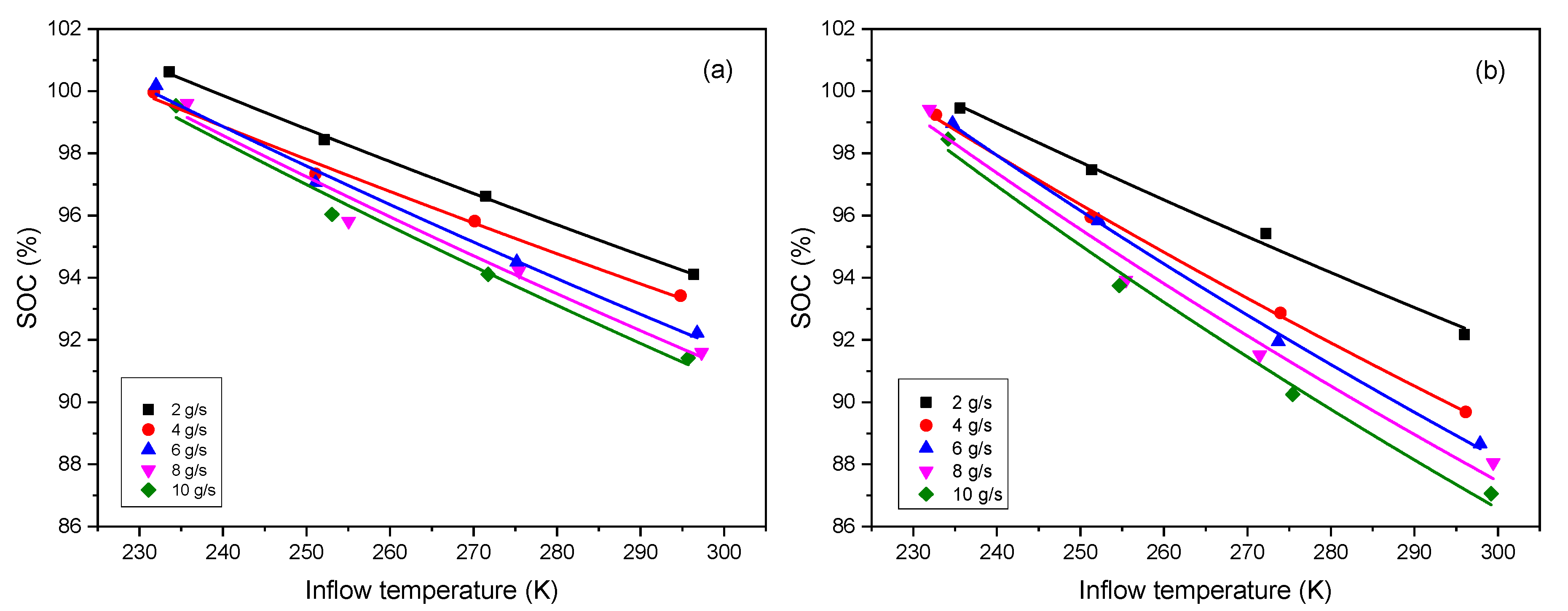
3.1. Effect of Inflow Temperature on SOC
The effect of inflow temperature on SOC under five different mass flow rates of 2, 4, 6, 8 and 10 g/s is presented. Equation (9) can be written in the following form:
Herein, we have J/K/kg, K, MPa. We fix . According to the definition of , the value of is supposed to be . However, the analytical solution is deduced based on the ideal gas equation of state, in fact, the behavior of hydrogen during the refueling process is far away from the one of an ideal gas. If taking consideration of a compressibility factor into the equation of state, , we can obtain a new form of Equation (9), i.e.:
where , K/MPa [17]. Since , it can be found that , i.e., the value of can be modified to be a smaller one in this way. If another method is used, such as the Redlich-Kwong equation, we can obtain another small . Considering different ways to deal with the equation, various values of can be obtained, thus, can be set as a variable parameter in the Equation (13). Besides, is another unknown parameter. Both of them are set as the fitted parameters. Equation (13) is utilized to fit with the reference data [14], the results show a good agreement as shown in Figure 1, and the values of fitted parameters are listed in Table 1.
As seen from Equation (13), the variation of SOC with inflow temperature is an inverse proportional function, but the fitting shows a linear trend. The explanation is as follows: a series expansion gives , when . Applying this result to Equation (13), we have , where , , , so we can obtain that . This is the reason why the fitting shows a linear trend.
3.2. Effect of Mass Flow Rate on SOC
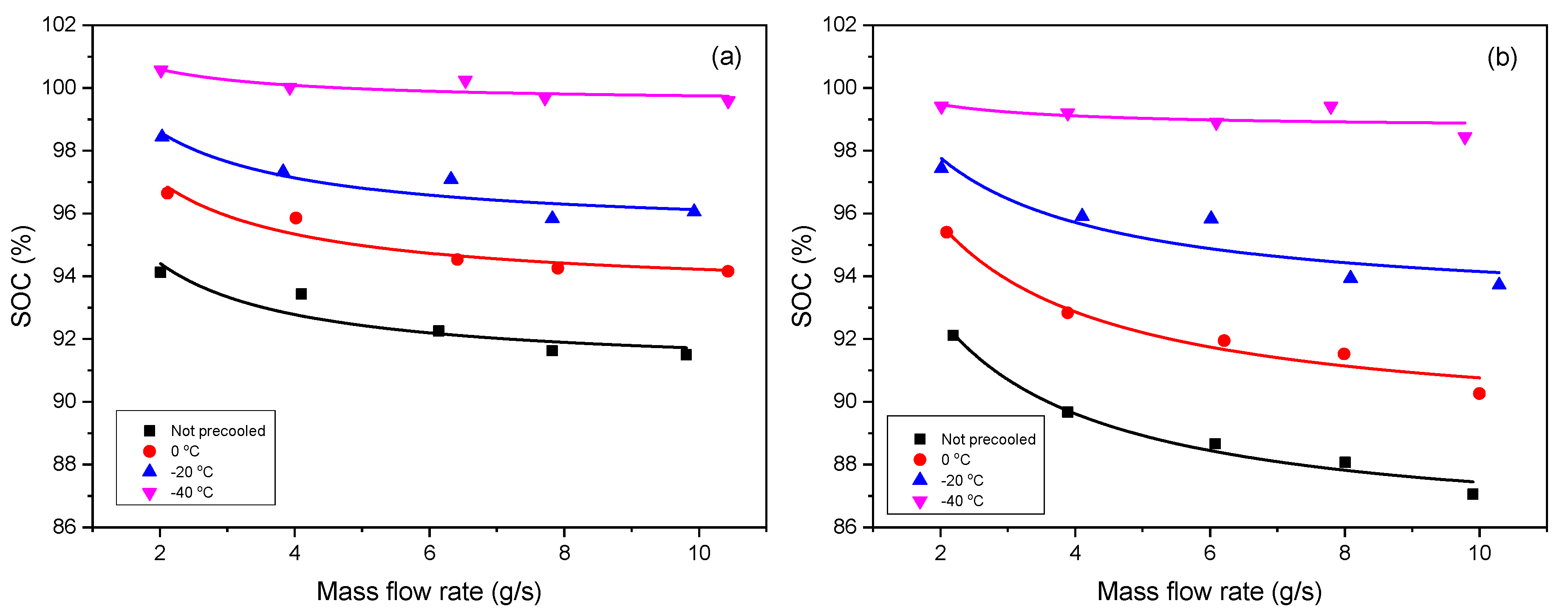
The effect of mass flow rate on SOC under different inflow temperatures of , , 0 °C and not precooled is presented. Herein, according to the definition of , we can use (, and expressed in the unit g/s here for source data of fitting) in the Equation (12). Like in Section 3.1, is also set as a fitted parameter, and is the other one. As shown in Figure 2, the deduced formula can express the reference data very well. Table 2 shows the values of the fitted parameters, where the non-precooled temperature is same as the ambient temperature.
Inflow temperature and mass flow rate are the key factor when investigating the contribution of refueling parameters to the SOC, and both have a negative influence on the SOC. The higher the inflow temperature is, the less the SOC is, and so is the mass flow rate. Given that the inflow temperature is low, it means the hydrogen gas has been precooled in advance, under a certain limited final temperature (e.g., 85 °C, the upper temperature limit stipulated in SAE J2601), the tank is supposed to be filled with more gas. Supposing that the mass flow rate is high, meaning the tank is charged very fast, it leads to the heat exchange between the gas and environment being slow, and the hydrogen temperature inside tank easily reaches the limit temperature (e.g., 85 °C), thus, the SOC should be low. In addition, it can also be found the Type IV tank is more sensitive than Type III to the variation of the refueling parameters, as we can see that the lines for the Type IV tank have stronger trend of separation and divergence than those for the Type III tank when the inflow temperature increase.
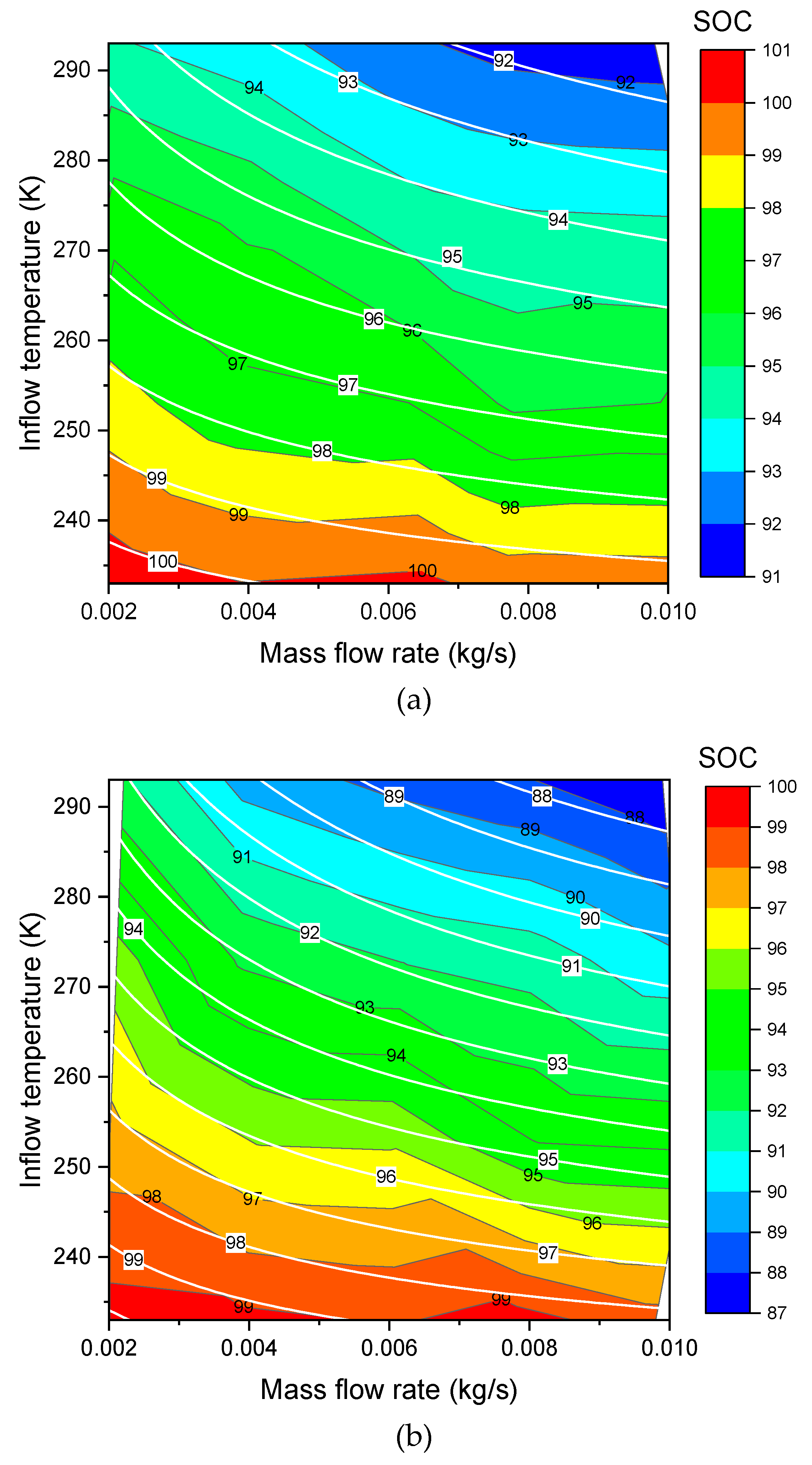
3.3. Effects of Inflow Temperature and Mass Flow Rate on SOC
As seen from Section 3.1 and Section 3.2, a deviation of the fitted parameters exists in the different cases. Herein, a new modified formula is proposed taking the effects of inflow temperature and mass flow rate simultaneously into consideration. According to [3,18], the heat transfer coefficient is proportional to the Nusselt number, while the Nusselt number is the exponential function of the Reynolds number, and the Reynolds number is proportional to the mass flow rate, thus the functional relationship between the heat transfer coefficient and the mass flow rate (unit kg/s is used here for expressing source data of fitting) can be modified as follows:
Combining Equation (15) with , it is obtained that:
where , . We use this new definition of in Equation (11), and thus the new analytical model can be written as follows:
Herein, we fix . Now , and are the new fitted parameters. The new formula of Equation (17) can be used to do the three dimensional (3D) surface fitting for the Type III (Figure 3a, Figure 4a) and Type IV (Figure 3b, Figure 4b). As shown in these figures, the fit shows a good agreement. The values of the fitted parameters are shown in the Table 3. Exchange of X axis and Y axis of the contour plotting (changed from Figure 3 to Figure 4) does not affect the values of the fitted parameters in Table 3.
4. Conclusions
(1) SOC, defined as the ratio of the hydrogen density during refueling to the full-filling density, can be transformed to be the ratio of the hydrogen mass to the full-filling mass, and the full-filling mass can be calculated if the volume of the tank is given.
(2) The analytical solution of SOC can be obtained from a thermodynamic model. This model is a lumped parameter model, and mass balance equation and energy balance equation are applied. The deduced formula can be used to determine SOC from the refueling parameters.
(3) The effects of inflow temperature and mass flow rate on SOC are presented, both of them have a negative effect on SOC. To improve SOC, it is supposed to precool the hydrogen gas (decrease the inflow temperature) in advance and reduce the mass flow rate.
(4) The Type IV tank is more sensitive than Type III to the refueling parameters. When the refueling condition varies, the SOC of Type IV changes more than that of Type III.
(5) The thermodynamic model will be improved and extended to the dual zone (gas zone and wall zone) model, not only the behavior of the hydrogen gas is researched, but also the effect of the tank wall will be considered.
Author Contributions
Conceptualization, J.X.; Methodology, J.X. and S.M.; Software, X.W.; Supervision, P.B.; Visualization, S.D.; Writing—original draft, S.M. and X.W.; Writing—review & editing, J.X. and T.Y.
Funding
This research was funded by National Natural Science Foundation of China (NSFC), grant number 51476120.
Acknowledgments
We thank the financial supports from the Quebec Merit Scholarship for Foreign Students and the Fundamental Research Funds for the Central Universities of China.
Conflicts of Interest
The authors declare no conflict of interest.
Nomenclature
| heat transfer coefficient between hydrogen and ambient fluid, kW/m2/K | (final) temperature of hydrogen, K | ||
| internal surface area of tank, m2 | initial temperature in tank, K | ||
| constant-pressure specific heat, kJ/kg/K | temperature of ambient fluid, K | ||
| constant-volume specific heat, kJ/kg/K | hydrogen inflow temperature, K | ||
| specific enthalpy of hydrogen, kJ/kg | characteristic temperature, , K | ||
| coefficient of , | specific internal energy, kJ/kg | ||
| (final) hydrogen mass in tank, kg | Greek symbols | ||
| initial hydrogen mass in tank, kg | dimensionless heat transfer coefficient, | ||
| hydrogen mass flow rate, g/s or kg/s | ratio of specific heats, | ||
| (final) pressure, MPa | initial mass fraction, | ||
| initial pressure, MPa | modified initial mass fraction, | ||
| hydrogen gas constant, | dimensionless pressure, | ||
| time variable or fill time, s | dimensionless temperature, | ||
| characteristic time, , s | dimensionless characteristic temperature, | ||
References
- Chu, H.L.; Wu, G.T.; Xiong, Z.T.; Guo, J.P.; He, T.; Chen, P. Structure and hydrogen storage properties of calcium borohydride diammoniate. Chem. Mater. 2010, 22, 6021–6028. [Google Scholar] [CrossRef]
- Acosta, B.; Moretto, P.; Miguel, N.D. JRC reference data from experiments of on-board hydrogen tanks fast filling. Int. J. Hydrog. Energy 2014, 39, 20531–20537. [Google Scholar] [CrossRef]
- Guo, J.; Yang, J.; Zhao, Y. Investigations on temperature variation within a type III cylinder during the hydrogen gas cycling test. Int. J. Hydrogen Energ. 2014, 39, 13926–13934. [Google Scholar] [CrossRef]
- Galassi, M.C.; Baraldi, D.; Iborra, B.A. CFD analysis of fast filling scenarios for 70MPa hydrogen type IV tanks. Int. J. Hydrog. Energy 2012, 37, 6886–6892. [Google Scholar] [CrossRef]
- Zheng, J.; Guo, J.; Yang, J. Experimental and numerical study on temperature rise within a 70MPa type III cylinder during fast refueling. Int. J. Hydrog. Energy 2013, 38, 10956–10962. [Google Scholar] [CrossRef]
- Jin, Z.; Chen, F.; Qian, J. Numerical analysis of flow and temperature characteristics in a high multi-stage pressure reducing valve for hydrogen refueling station. Int. J. Hydrog. Energy 2016, 41, 5559–5570. [Google Scholar] [CrossRef]
- Bourgeois, T.; Ammouri, F.; Weber, M. Evaluating the temperature inside a tank during a filling with highly-pressurized gas. Int. J. Hydrog. Energy 2015, 40, 11748–11755. [Google Scholar] [CrossRef]
- Miguel, N.D.; Acosta, B.; Baraldi, D. The role of initial tank temperature on refuelling of on-board hydrogen tanks. Int. J. Hydrog. Energy 2016, 41, 8606–8615. [Google Scholar] [CrossRef]
- Monde, M.; Woodfield, P.; Takano, T. Estimation of temperature change in practical hydrogen pressure tanks being filled at high pressures of 35 and 70MPa. Int. J. Hydrog. Energy 2012, 37, 5723–5734. [Google Scholar] [CrossRef]
- Xiao, J.S.; Bénard, P.; Chahine, R. Charge-discharge cycle thermodynamics for compression hydrogen storage system. Int. J. Hydrog. Energy 2016, 41, 5531–5539. [Google Scholar] [CrossRef]
- Xiao, J.S.; Bénard, P.; Chahine, R. Estimation of final hydrogen temperature from refueling parameters. Int. J. Hydrog. Energy 2017, 42, 7521–7528. [Google Scholar] [CrossRef]
- Cheng, J.; Xiao, J.S.; Bénard, P. Estimation of Final Hydrogen Temperatures During Refueling 35 MPa and 70 MPa Tanks. Energy Procedia 2017, 105, 1363–1369. [Google Scholar] [CrossRef]
- Xiao, J.S.; Cheng, J.; Wang, X.; Bénard, P.; Chahine, R. Final hydrogen temperature and mass estimated from refueling parameters. Int. J. Hydrog. Energy 2018, 43, 22409–22418. [Google Scholar] [CrossRef]
- Cebolla, R.O.; Acosta, B.; Miguel, N.D. Effect of precooled inlet gas temperature and mass flow rate on final state of charge during hydrogen vehicle refueling. Int. J. Hydrog. Energy 2015, 40, 4698–4706. [Google Scholar] [CrossRef]
- Xiao, J.S.; Wang, X.; Bénard, P. Determining hydrogen pre-cooling temperature from refueling parameters. Int. J. Hydrog. Energy 2016, 41, 16316–16321. [Google Scholar] [CrossRef]
- Wang, X.; Xiao, J.S.; Bénard, P. Final Hydrogen Mass Determined from Refueling Parameters. Energy Procedia 2017, 105, 1370–1375. [Google Scholar] [CrossRef]
- Chen, H.; Zheng, J.; Xu, P. Study on real-gas equations of high pressure hydrogen. Int. J. Hydrog. Energy 2010, 35, 3100–3104. [Google Scholar] [CrossRef]
- Woodfield, P.L.; Takano, T.; Monde, M. Characteristics of Heat Transfer for Hydrogen and Wall During Filling Hydrogen into Actual Tank at High Pressure. In Proceedings of the ASME/JSME 2007 Thermal Engineering Heat Transfer Summer Conference collocated with the ASME 2007 Inter PACK Conference, Vancouver, BC, Canada, 8–12 July 2007. [Google Scholar]
Figure 1.
Effect of inflow temperature (unit K is necessary for thermodynamic calculation) on SOC under different mass flow rates (unit g/s is used here only for simplifying the legends) for (a) Type III tank and (b) Type IV tank (Symbol: data [14], Line: fitting).
Figure 1.
Effect of inflow temperature (unit K is necessary for thermodynamic calculation) on SOC under different mass flow rates (unit g/s is used here only for simplifying the legends) for (a) Type III tank and (b) Type IV tank (Symbol: data [14], Line: fitting).

Figure 2.
Effect of mass flow rate (unit g/s is used here for expressing source data of fitting) on SOC under different inflow temperatures (unit °C is used for expressing experimental condition) for (a) Type III tank and (b) Type IV tank (Symbol: data [14], Line: fitting).
Figure 2.
Effect of mass flow rate (unit g/s is used here for expressing source data of fitting) on SOC under different inflow temperatures (unit °C is used for expressing experimental condition) for (a) Type III tank and (b) Type IV tank (Symbol: data [14], Line: fitting).

Figure 3.
Contours of SOC over inflow temperature (X) and mass flow rate (Y) for (a) Type III tank and (b) Type IV tank (Color fill and black line: data [14], white line: model fitting).
Figure 3.
Contours of SOC over inflow temperature (X) and mass flow rate (Y) for (a) Type III tank and (b) Type IV tank (Color fill and black line: data [14], white line: model fitting).

Figure 4.
Contours of SOC over mass flow rate (X) and inflow temperature (Y) for (a) Type III tank and (b) Type IV tank (Color fill and black line: data [14], white line: model fitting).
Figure 4.
Contours of SOC over mass flow rate (X) and inflow temperature (Y) for (a) Type III tank and (b) Type IV tank (Color fill and black line: data [14], white line: model fitting).


Table 1.
Parameter values for effect of inflow temperature on SOC under different mass flow rates.
| Case of Mass Flow Rate | Parameter | Type III | Type IV | ||
|---|---|---|---|---|---|
| Value | Standard Error | Value | Standard Error | ||
| 2 g/s | 3.06895 | 0.09539 | 2.43893 | 0.21307 | |
| 25.0915 | 0.03528 | 25.01956 | 0.10857 | ||
| 4 g/s | 3.08553 | 0.27222 | 1.63482 | 0.07602 | |
| 24.83858 | 0.0967 | 25.05608 | 0.06402 | ||
| 6 g/s | 2.36404 | 0.22206 | 1.32689 | 0.07263 | |
| 25.01534 | 0.1187 | 25.22366 | 0.07874 | ||
| 8 g/s | 2.21015 | 0.39765 | 1.26377 | 0.23178 | |
| 24.99006 | 0.23809 | 25.11684 | 0.26374 | ||
| 10 g/s | 2.09046 | 0.28239 | 1.13221 | 0.14616 | |
| 24.97778 | 0.17568 | 25.09859 | 0.18884 | ||
Table 2.
Parameter values for effect of mass flow rate on SOC under different inflow temperatures.
| Case of Inflow Temperature | Parameter | Type III | Type IV | ||
|---|---|---|---|---|---|
| Value | Standard Error | Value | Standard Error | ||
| Not precooled | 30.52763 | 0.15174 | 28.76612 | 0.11574 | |
| 0.30976 | 0.08068 | 0.74662 | 0.08333 | ||
| 0 °C | 29.29102 | 0.10452 | 27.93052 | 0.14825 | |
| 0.39768 | 0.07708 | 0.88248 | 0.1438 | ||
| −20 °C | 27.79269 | 0.12976 | 27.07205 | 0.23431 | |
| 0.49182 | 0.14135 | 0.8583 | 0.31881 | ||
| −40 °C | 26.79338 | 0.06061 | 26.57885 | 0.09415 | |
| 0.24821 | 0.10236 | 0.16917 | 0.1507 | ||
Table 3.
Fitted parameters showing effect of both inflow temperature and mass flow rate on SOC.
| Parameter | Type III | Type IV | ||
|---|---|---|---|---|
| Value | Standard Error | Value | Standard Error | |
| 25.0288 | 0.05962 | 25.15657 | 0.07491 | |
| 0.43528 | 0.07647 | 0.11065 | 0.02216 | |
| 0.32364 | 0.03384 | 0.47913 | 0.03749 | |
© 2019 by the authors. Licensee MDPI, Basel, Switzerland. This article is an open access article distributed under the terms and conditions of the Creative Commons Attribution (CC BY) license (http://creativecommons.org/licenses/by/4.0/).
Share and Cite
MDPI and ACS Style
Xiao, J.; Ma, S.; Wang, X.; Deng, S.; Yang, T.; Bénard, P. Effect of Hydrogen Refueling Parameters on Final State of Charge. Energies 2019, 12, 645. https://doi.org/10.3390/en12040645
AMA Style
Xiao J, Ma S, Wang X, Deng S, Yang T, Bénard P. Effect of Hydrogen Refueling Parameters on Final State of Charge. Energies. 2019; 12(4):645. https://doi.org/10.3390/en12040645
Chicago/Turabian StyleXiao, Jinsheng, Shuo Ma, Xu Wang, Shanshan Deng, Tianqi Yang, and Pierre Bénard. 2019. "Effect of Hydrogen Refueling Parameters on Final State of Charge" Energies 12, no. 4: 645. https://doi.org/10.3390/en12040645
Note that from the first issue of 2016, this journal uses article numbers instead of page numbers. See further details here.