A Review of Airside Heat Transfer Augmentation with Vortex Generators on Heat Transfer Surface


RCUK Centre for Sustainable Energy Use in Food Chains (CSEF), Institute of Energy Futures, Brunel University London, Uxbridge, Middlesex UB8 3PH, UK
*
Author to whom correspondence should be addressed.
Energies 2018, 11(10), 2737; https://doi.org/10.3390/en11102737
Submission received: 13 September 2018
/
Revised: 2 October 2018
/
Accepted: 10 October 2018
/
Published: 12 October 2018
(This article belongs to the Section I: Energy Fundamentals and Conversion)
Abstract
:Heat exchanger performance can be improved via the introduction of vortex generators to the airside surface, based on the mechanism that the generated longitudinal vortices can disrupt the boundary layer growth, increase the turbulence intensity and produce secondary fluid flows over the heat transfer surfaces. The key objective of this paper is to provide a critical overview of published works relevant to such heat transfer surfaces. Different types of vortex generator are presented, and key experimental techniques and numerical methodologies are summarized. Flow phenomena associated with vortex generators embedded, attached, punched or mounted on heat transfer surfaces are investigated, and the thermohydraulic performance (heat transfer and pressure drop) of four different heat exchangers (flat plate, finned circular-tube, finned flat-tube and finned oval-tube) with various vortex-generator geometries, is discussed for different operating conditions. Furthermore, the thermohydraulic performance of heat transfer surfaces with recently proposed vortex generators is outlined and suggestions on using vortex generators for airside heat transfer augmentation are presented. In general, the airside heat transfer surface performance can be substantially enhanced by vortex generators, but their impact can also be significantly influenced by many parameters, such as Reynolds number, tube geometry (shape, diameter, pitch, inline/staggered configuration), fin type (plane/wavy/composite, with or without punched holes), and vortex-generator geometry (shape, length, height, pitch, attack angle, aspect ratio, and configuration). The finned flat-tube and finned oval-tube heat exchangers with recently proposed vortex generators usually show better thermohydraulic performance than finned circular tube heat exchangers. Current heat exchanger optimization approaches are usually based on the thermohydraulic performance alone. However, to ensure quick returns on investment, heat exchangers with complex geometries and surface vortex generators, should be optimized using cost-based objective functions that consider the thermohydraulic performance alongside capital cost, running cost of the system as well as safety and compliance with relevant international standards for different applications.
1. Introduction
Heat exchangers are used for heat transfer between two or more fluids with temperature difference, which are widely used in many diverse industries and applications, including the process and chemical industries, transportation, air conditioning and refrigeration [1]. High-efficiency heat exchangers can reduce the fluid inventory, cost of materials and energy consumption, leading to increased efficiency and return on investment, and lower environmental impacts. Significant research has been carried out to date on improving heat exchanger performance since the first published paper on the subject by Joule in 1861 [2]. For the typical applications of an air-cooled heat exchanger, due to the inherently lower thermal conductivity of gas, and thus the lower heat transfer coefficient, than that of liquid or two-phase flow, the airside resistance generally accounts for 85% or more of the total thermal resistance. To improve performance to meet the demands for high efficiency and low cost, the most common way is to use heat transfer surfaces those are periodically interrupted along the streamwise direction [3,4]. Some typical examples are heat transfer surfaces mounted with louvred fin, offset fin, offset strip fin, rectangular plate-fin, and vortex generators (VGs) such as fins, ribs and wings. Their mechanisms for heat transfer augmentation are usually to disrupt the boundary layer growth, to increase the turbulence intensity, and to generate secondary flows such as swirl or vortices [5,6,7].
These interrupted surfaces can significantly improve the heat transfer performance, but are usually associated with a high pressure-drop penalty. In contrast to the main-flow-interrupted enhancement surfaces with louvres or strip fins, the secondary-flow-interrupted ones with VGs not only improve the heat transfer performance but also offer comparatively low pressure drop [6,7,8,9]. These advantages make them suitable for industrial thermal energy recovery systems, where, the high-pressure fluid flows inside the channels or tubes, and the high-temperature low pressure exhaust gas flows across the channels or tubes [10,11]. However, VGs also lead to complex flow through heat transfer surfaces, with heat transfer enhancement becoming dependent on many important length scales and geometric features [12]. Therefore, a deeper understanding of the thermohydraulic performance of heat transfer surfaces with VGs is needed to enable designers to assess the feasibility and viability of vortex-induced airside heat transfer enhancement for specific applications.
To contribute to this effort, this paper presents a critical review of published works on the thermohydraulic performance of heat transfer surfaces with different VGs, with the purpose of developing a systematic evaluation of vortex-induced airside heat transfer enhancement. Different VG enhancement methods are presented for four different heat transfer surfaces, including VGs on flat plates, VGs in finned circular-tube heat exchangers, VGs in finned flat-tube heat exchangers and VGs in finned oval-tube heat exchangers, and their flow and heat transfer interactions are carefully analyzed under different operating conditions. The effects of operating conditions and various design parameters on thermohydraulic performance, particularly for the heat transfer surfaces with recently proposed VGs, are demonstrated with the goal of contributing to an improved understanding of heat exchanger designs, with a view to developing higher-performance heat transfer surfaces—particularly for applications with specific constraints on size and extreme limitations on thermohydraulic performance.
2. Vortex Generators
As constructional details, heat exchangers are classified into tubular heat exchangers, plate heat exchangers, extended surface heat exchangers and regenerators [1]. Plate-fin heat exchangers and finned-tube heat exchangers are the most common examples of extended surface heat exchangers. VGs are commonly used in the extended fin surface to further increase the heat transfer rate, which enhance the heat transfer by interacting with and disturbing the thermal boundary layer between the heat exchanger surface and the secondary fluid flowing across the surface. Depending on the specific application, the VG devices differ in their geometry, dimensions and integration on the heat exchanger surface, leading to two main categories of generated vortex: transverse and longitudinal. Generally, the longitudinal vortices are more effective than transverse vortices in enhancing heat transfer with only a small increase in pressure drop [13]. Four surface protrusion designs are commonly used for longitudinal-vortex-induced heat transfer enhancement. As shown in Figure 1, they are delta wing, rectangular wing, delta winglet and rectangular winglet [8,12,14]. The geometry parameters of these VGs, such as the angle of attack (α) and aspect ratio (Λ), can have a significant influence on their heat transfer capability, and have thus received increased research attention.
Alongside the four main types, several other VGs have been proposed and investigated in recent years. Wang et al. [6,9], Lin et al. [15] and Gong et al. [16] proposed annular winglets and wave-element VGs, as shown in Figure 2a, particularly for application to finned-tube heat exchangers. He et al. [17] proposed V-deployed VG arrays, as shown in Figure 2b, to emulate locomotion of animals in nature. Zhou et al. [18,19] investigated several straight- and curved-surface winglet VGs with or without punched holes, namely: rectangular winglet, trapezoidal winglet, delta winglet, curved rectangular winglet, curved trapezoidal winglet and curved delta winglet, as shown in Figure 2c, respectively abbreviated as RW, TW, DW, CRW, CTW and CDW. Lotfi et al. [20,21] considered the application of four different VG types on smooth wavy-finned oval-tube heat exchangers, as shown in Figure 2d, which were the rectangular trapezoidal winglet, angle rectangular winglet, curved angle rectangular winglet and wheeler wishbone, respectively abbreviated as RTW, ARW, CARW and WW. Wu et al. [22] proposed composite fin designs incorporating VGs on slit fins, as shown in Figure 2e. All the newly proposed VGs demonstrate improvements to the thermohydraulic performance of the heat exchangers. Of particular note is the novel longitudinal tube fin designs proposed by Stehlík et al. [10], shown in Figure 2f, which provides the heat transfer intensification through the increased heat transfer area and the flow turbulence, and could have the applications in heat recovery in power plants, where fin geometry and enhancement can effectively reduce the heat exchanger size and costs.
3. Experimental and Numerical Methods
3.1. Experiment Techniques
Experimentation is so important in engineering and science that the researchers should be familiar with the measurement methods and the analysis techniques for data reduction. Measurement of thermohydraulic performance frequently require accurate flow rate, pressure and temperature measurements. The experiment techniques investigating the thermohydraulic performance of the airside heat transfer surfaces include laser light sheets (LLS), laser doppler velocimetry (LDV), hot-wire anemometry, particle image velocimetry (PIV), liquid crystal thermography (LCT), the naphthalene sublimation technique and infrared thermography. Table 1 indicates the representative experiment techniques for flow rate, pressure and temperature measurements in chronological order. These experiment techniques commonly concentrate on the extended fin surfaces, regardless of the tube type of heat exchanger, and one technique can be used for different heat transfer surfaces and different VGs; therefore, these techniques are not separately presented based on the types of either the tube or the VGs. In this section, we seek to demonstrate the experimental methods and show the generalized experimental systems, and pay particular attention to the measurements of flow visualization and temperature distribution, because they are very important for a deeper understanding of flow and heat transfer interactions.
Fiebig et al. [24], Tiggelbeck et al. [25] and Gentry and Jacobi [35] employed the LLS method for flow visualization. As shown in Figure 3a, test plates with VGs were placed in a wind tunnel and an electrically heated wire was used to evaporate oil on the surface of the wire. The smoke generated by the evaporating oil was photographed as it passed over the VGs using a high-speed camera and helium-neon laser to illuminate the flow.
Wang et al. [6,9], Gentry and Jacobi [35], Leu et al. [39], Allison and Dally [44] and Wang et al. [45] performed flow visualization in a transparent water tunnel using the dye-injection technique. The velocity in the water tunnel was measured by recording the time required for a dye marker to traverse a known distance. The vortex strength can be determined with two different techniques: by direct measurement, using the vane-type vortex meter as illustrated in Figure 3b, and a potential-flow model and flow visualization from the observed trajectories of the vortices at several streamwise locations from the leading edge.
Chen and Shu [38] conducted three-component mean and fluctuating velocity measurements using the LDV to obtain the near-wall axial mean velocity, axial vorticity and the corresponding turbulent kinetic energy for a heated plate installed at the bottom wall of a duct. A smoke wire was located upstream of the apparatus to generate sub-micron particles. Flow structure measurements were conducted at four cross-sectional planes and two planes vertically perpendicular to the cross section, and the near-wall axial vorticity was obtained from the mean component velocities.
Hernon and Patten [49] conducted hot-wire measurements to obtain the velocity profiles downstream of a delta winglet pair (DWP) placed on an unheated flat surface. The mean and fluctuating velocities were measured by a TSI IFA300 constant temperature anemometer system, which can obtain the boundary layer profile shape and measure the boundary layer thickness. The authors highlighted advantages of hot-wire measurements over other measurement techniques, these included increased temporal and spatial resolution, enabling further elucidation of critical flow features that can enhance understanding of the flow and heat transfer processes taking place.
Min et al. [53] applied the PIV measurement technique using glycerol particles with a charged coupled device (CCD) camera to carry out flow visualization on a heated flat plate. The glycerol particle generator produced particles of approximately 1 µm in diameter and high concentration, so that sufficient light could be scattered in the visualization domain for detection by the CCD camera.
Fiebig et al. [24,27,29] and Tiggelbeck et al. [25] used the transient LCT technique to investigate the impact of longitudinal vortices on the local heat transfer coefficient. With this technique, a thin film of liquid crystals was coated on the heat transfer surface and the development of specific isotherms during transient heating was recorded using laser light and the property of thermochromic liquid crystals to reflect incident monochromatic light from the laser only at specific temperatures.
Gentry and Jacobi [30], Yoo et al. [36] and Shi et al. [43] investigated the interactions between the vortex and boundary layer using naphthalene sublimation experimental techniques. During the experiment, the Naphthalene formed part of the plate surface on solidification and polishing. The naphthalene surface can extend over the entire streamwise length of the plate and develop a thin lip at the leading and trailing edges. The local sublimation depths were measured using a non-contact, optical technique (known as laser triangulation) to yield the local and average mass transfer coefficients, then to also find the local and average heat transfer coefficients through the heat and mass analogy.
O’Brien et al. [40] employed a transient technique for heat transfer measurements, in which a heated airflow was suddenly introduced to the test section and the high-resolution local fin surface temperature distributions were obtained by an imaging infrared camera (FLIR PRISM DS). Leu et al. [39], Min et al. [53] and Aris et al. [14] also applied infrared thermography to measure surface temperature distributions. This method presents several advantages over the thermochromic liquid crystals to measure the surface temperature distribution, which can be applied over a wide available temperature range, obtain high spatial resolution and excellent thermal resolution, and employ full-field direct digital data acquisition and processing.
3.2. Numerical Methodology
Numerical modelling is a science that can be helpful for studying fluid flow and heat transfer by solving mathematical equations. It has been proven an effective and reliable tool to provide detailed insight into flow structure, velocity field, pressure distribution and temperature gradient at a lower cost due to its reduced requirement for experiments [60,61], which is important for comprehensive investigation of fluid flow and heat transfer interaction and novel VG design and optimization before prototype construction. Because the same numerical methodology can be used for different heat transfer surfaces, in this section we present the mentioned approaches, not according to the heat exchanger type, but the numerical aspects, e.g., solver, assumption, model, boundary condition, discretization, etc. Table 2 presents the key numerical methodology applied in the numerical studies of the published works in chronological order.
The computational solvers include modified marker-and-cell (MAC) algorithm, SOLA algorithm, STAR-CD, CFX solver and FLUENT solver. The MAC method is a well-known technique, used to solve time-dependent incompressible fluid flow problems since the 1960s. It uses an Eulerian finite-difference formulation with pressure and velocity as the primary dependent variables [108]. Biswas et al. [64,67,70], Deb et al. [69], Sinha et al. [94] and Saha et al. [99] modified the MAC algorithm to solve the governing equations of fluid flow and heat transfer. SOLA algorithm is a finite-difference technique to solve the Navier–Stokes equations of an incompressible fluid, which is also based on the MAC method and employed by Fiebig et al. [62] and Zhu et al. [65,66] to obtain the velocity structure and temperature field on heat transfer surfaces. Hirt et al. [109] described the basic SOLA algorithm for confined flows and modifications necessary for free or curved rigid surface boundaries and provided the corresponding flow chart and the FORTRAN codes. STAR-CD, developed by CD-adapco Ltd., is a solver particularly aimed at engine productions, and was used by Lemouedda et al. [88] to simulate the fluid flow and heat transfer on the fin surface. Both CFX and FLUENT solvers are high-performance computational fluid dynamics (CFD) software belonging to ANSYS Inc. CFX shows outstanding accuracy, robustness and speed for rotating machinery, and was applied by Lotfi et al. [21] to examine the velocity structure and temperature field in wavy fins with different VGs. FLUENT has well-validated physical modelling capable of delivering fast, accurate results for multiphysics applications, and has been widely applied in numerical simulation and is considered to be a very powerful CFD tool. As shown in Table 2, most of the published CFD works in the past ten years have applied FLUENT software, for example, References [4,16,48,77,78,79,80,82,83,84,85,86,87,89,90,91,92,93,95,96,100,103,105,106,107].
The assumption in the numerical works mentioned in Table 2 is usually incompressible and Newtonian, with constant properties for the fluid, three-dimensional for the computational domain, and with negligible buoyance force and viscous dissipation. To the best of the authors’ knowledge, these assumptions are valid for low-pressure flow covering short temperature variation. However, some engineering problems involve high-pressure flow and cover large temperature variation, leading to deviation from the assumption of incompressible fluid, constant properties and negligible buoyance force. In those cases, the temperature-dependent thermophysical properties, or even the real-gas model of thermodynamic properties, should be employed in the numerical modelling, and the influence of the gravity should be considered. In addition, for highly compressible flows, the temperature distribution near the heat transfer surface may be significantly different from the bulk flow; in that case, the heating by viscous dissipation should be taken into account.
From Table 2, it is noted that the standard k–ε model, RNG k–ε model and SST k–ε model are usually applied to investigate the effect of turbulence on the flow field caused by VGs. As pointed out by Cebeci et al. [110], the standard k–ε model is the most widely used and validated model, but does not function well for flows involving significant curvature, swirl, sudden acceleration, separation and low-Re regions. The RNG k–ε model and SST k–ε model modify the standard k–ε model to improve simulations for swirling flows and flow separation, but the RNG k–ε model is not as stable as the standard k–ε model and the SST k–ε model needs fine mesh close to the wall and also over-predicts turbulence in regions with large normal strain, e.g., stagnation regions and regions with strong acceleration. The choice of turbulence model depends on many considerations, e.g., fluid thermophysical properties, calculation accuracy, computational resource, simulation time, capability and limitations of various models, etc. For example, if the real-gas thermodynamic properties are considered in the numerical modellings, the simulation time will be much longer than those employing an assumption of fluid constant properties.
As indicated in Table 2, the uniform inlet velocity and constant inlet temperature are generally assumed at the inlet of the computational domain, while a few researchers apply periodical fully developed fluid flow conditions at the inlet and outlet of the flow passage. To simplify the physical model and save the computational time, a geometrical element with periodic or symmetry boundary conditions is usually applied as the simulation domain. The periodic boundary condition is used for computation geometries and flow patterns with a periodically repeating nature, while the symmetry boundary condition is for those having mirror symmetry; both of them can significantly reduce the required simulation time. However, to the best of the authors’ knowledge, for periodic and symmetry boundary conditions, it is important to verify the obtained solution critically, because it may introduce unphysical correlations.
For applying numerical methods to solve the governing equations, the finite-volume method has been successfully applied in simulations using the local conservation principle. As demonstrated in Table 2, the second-order upwind scheme, the power scheme and the third-order QUICK scheme are usually used to discretize the convection terms, the second-order central difference scheme is always applied to discretize the diffusion terms and the SIMPLE or SIMPLEC algorithms are generally employed in order to implement the coupling between pressure and velocity. The choice of discretization scheme also relies on many considerations, e.g., ratio of convective term to diffusive one, accuracy, robustness, etc. The second-order upwind scheme and the QUICK scheme are good for all ratios of convective terms to diffusive ones, while the power scheme is suitable for intermediate values. The power scheme and the QUICK scheme can be more accurate than the second-order upwind scheme, but at the expense of numerical stability. The SIMPLE algorithm employs a starting guess of pressure and velocity to solve the momentum equation, but the starting guess may not be correct, so that the obtained velocities will not satisfy continuity. SIMPLEC, as a modified form of the SIMPLE algorithm, usually performs better in situations in which the rate of convergence is limited by the pressure–velocity coupling, such as non-complex laminar flow cases [110].
4. Thermohydraulic Performances
Since the 1980s, the interaction of the flow structure and heat transfer and friction drag caused by VGs on the plate-fin and finned-tube heat exchangers has attracted much research attention. Table 1 and Table 2, respectively, summarize the representative experimental and numerical published works, considering the type of VGs and heat transfer surfaces, Re number range, key experimental or numerical methodologies and the measured characteristics. The thermohydraulic performance of heat exchangers is not only dependent on the geometry of VGs and operation conditions, but strongly determined by the type of heat transfer surface that controls the flow passage of the mainstream, so in this section, we provide more detailed information and comments regarding the thermohydraulic performance mentioned in Table 1 and Table 2 based on the different types of heat transfer surface, e.g., flat plates, finned circular-tube heat exchangers, finned flat-tube heat exchangers, finned oval-tube heat exchangers, etc. In addition, for each type of heat transfer surface, we focus on the interaction of flow and heat transfer, effect of geometry parameters, and the performance of recently proposed VGs. It should be pointed out that the Re number is calculated based on the channel height—the distance between two plates for plate-fin heat exchanger and the distance between two fins for the finned-tube heat exchangers.
4.1. Vortex Generators on Flat Plates
4.1.1. Interaction of Flow and Heat Transfer
For laminar flow and heat transfer, Fiebig et al. [24,62] investigated the heat transfer enhancement and drag caused by delta wings or winglet pairs between flat plates for Re numbers ranging from 500 to 2270. Each wing or winglet pair was found to generate a pair of counter-rotating longitudinal vortices along their leading edges. The main flow field difference between the wing and the winglet pair was that the attached wing cannot generate a trailing edge wake, while the winglet wake was characterized by strong shear layers near the plane. The drag was found to be independent of Re number and VG geometry. The heat transfer ratio of a fin with and without VGs was independent of Re number with α up to 60°. Local heat transfer augmentation with a mean value of up to 50% was achieved as area ratio Ra > 50 (Ra = Ac/Av, where Ac is the area of channel wall and Av is the vortex-generator area), and the heat transfer enhancement per unit vortex-generator area was highest for the delta wing, followed by DWPs and RWPs.
Biswas et al. [68,69,70] numerically studied heat transfer and flow structure of laminar flows caused by delta winglet or DWPs. The flow pattern that was described is as follows: the main vortex was formed by the flow separation at the leading edge of the winglet, while the corner vortex showed a horseshoe-vortex-like characteristic feature. These vortices were found to swirl the flow around the axis in the mainstream direction, strongly enhancing the mixing of the hot and cold fluids, and consequently leading to higher heat transfer but increased fluid friction.
To capture the interaction between the vortex and boundary layer, Gentry and Jacobi [30,35] introduced the local and average goodness factor for evaluation of delta wing VGs: local goodness factor (, where , with , where δb is the general boundary layer thickness and δc is the core-to-plate distance, and Pe is the Peclet number) and average goodness factor (, L is the plate length). Vortex strength was found to increase with Re number, ratio Λ, and angle α, but decay as the vortex was carried downstream. In regions where a vortex induced a surface-normal inflow, the local heat transfer coefficient can increase by three times over the baseline flow. For Re numbers ranging from 300 to 2000, the delta wing VGs can result in a 50–60% enhancement of average heat transfer for flow over the flat plate, and can cause two times higher pressure drop than the same channel flow without VGs.
For turbulent flow and heat transfer, Tiggelbeck et al. [25,26] tested a channel with single or double rows of DWPs with Re numbers of up to 8000. For an aligned two-row arrangement, the flow structure in the wake of the second row was qualitatively similar to that of the first row. The local heat transfer enhancement, normalized at the wake of the second row, was strongly dependent on the spacing of the two rows, and the maximum local heat transfer enhancement was found behind the second-row winglets for row spacings of 7–10 channel heights. For a staggered double-row configuration, lower heat transfer enhancement was found than for the aligned configuration, particularly for angle α near the critical value of 70° for the first row and 55° for the second.
Kotcioğlu et al. [31] investigated the heat transfer and flow structure for a rectangular channel developed between flat plates containing RWPs for Re numbers between 3000 and 30,000. Study of different winglet arrangements showed that an increased winglet inclination angle improved the heat transfer by increasing the mixing effect in the intermediate region between wing cascades. Friction factor f and average Nu number strongly depended on Re number and an increase in heat transfer coefficient was usually accompanied by a large pressure drop. Average Nu number and factor f correlations were derived with the geometry (a: width of the duct; b: height of the duct; c: length of winglet in streamwise direction; and β: inclination angle).
for Pr = 0.71 and 0 < β < 27°. The values of C0 and m were different for each channel configuration.
For much higher Re numbers (>50,000), Zhu et al. [65,66] found that the longitudinal vortices produced by the VGs can significantly elevate the level of turbulence kinetic energy in the flows, strongly disturb the thermal boundary layer near the wall, and thus result in clear heat transfer augmentation.
4.1.2. Effect of Geometry Parameters
For laminar flow and heat transfer, Tian et al. [83] and Sinha et al. [94] respectively, numerically investigated the effects of two different-shaped VGs (rectangular winglet pair (RWP) and DWP) with two different configurations (common-flow-down (CFD) and common-flow-up (CFU), as shown in Figure 4a) on the thermohydraulic performance of a channel flow. As shown in Figure 4b, the heat transfer enhancement by the VGs occurred both in the region with mounted VGs and that in the long distance downstream. For the channel with RWP and DWP, the average Nu number was respectively increased by 8–46% and 3–26% in the studied Re number range of 470 to 1700. The increase of Nu number with CFU configuration was higher than that of the CFD configuration. The friction factor of the channel with RWP was higher than that of DWP, and the friction factor of the channel with the CFU configuration was larger than that of the CFD configuration.
Sinha et al. [94] investigated the effects of different orientations of winglet arrays on the thermohydraulic performance for Re numbers ranging from 250 to 1580. Five different strategic placements were considered, including common-flow-up in series, common-flow-down in series, combined, inline rows of winglet, and staggered rows of winglet. These placements were respectively abbreviated as CFU-CFU, CFD-CFD, CFD-CFU, IRW and SRW. Among the different types of arrangements of VGs, the CFD-CFU configuration was found to perform best in terms of heat transfer, as well as quality factor (, where j is the Colburn factor ).
Wu and Tao [55] studied the effects of four different angle α: 15°, 30°, 45° and 60° for DWP on the heat transfer of channel flows for Re numbers in a range of 500–2000. The average Nu number was found to increase with increased α compared with that of a plain plate without DWP.
Biswas et al. [63,64] compared the flow and heat transfer characteristics for a built-in delta wing with and without a hole protruding from the bottom wall and found that the punched hole reduced the strength of the longitudinal vortices. They also found that the improvement of the heat transfer coefficient was relatively low compared to that of the case without any punched holes, but that the friction pressure drop significantly decreased.
Aris et al. [14] carried out experiments of delta wing in a rectangular duct to test the effects of angle α. Their wings were made from shape memory alloys and manufactured in a selective laser melting process, which was expected to change their shape to enhance heat transfer at high temperature and minimize flow pressure losses at low temperature. When the surface temperature varied from 20 °C to 65 °C, the angle α responded from 10° to 38°. Heat transfer can be improved up to 90% and 80%, respectively, by using the single and double wings at their activated positions. When the wings were activated, the flow pressure losses across the test section increased by between 7% and 63% of the losses at their de-activated positions for the single and double VGs, respectively.
Yang et al. [50] made a total of eight heat sinks and tested their channel flow thermohydraulic performance. Detailed geometries of heat sinks are shown in Figure 5a, including plain fin, delta VG fin, delta VGs with plain fin, semi-circular VG fin, triangular VG fin, triangular attack VGs, dimple VG fin and two-groups dimple VG fin, which can be grouped into four categories: plate-fin; plate with interrupted fin geometry, such as slit or louvre fin; plate with dense VGs, such as semi-circular, delta and dimple VGs; and plate with loose VGs, such as a dimple/protrusion structure but with sparse arrangement. As shown in Figure 5b, they found that the interrupted and dense VG configurations induced a greater pressure-drop penalty than heat transfer improvements, especially when operated at a lower frontal velocity. They suggested that the VGs operated at a higher frontal velocity were more beneficial than those with plain-fin geometry and that an asymmetric combination, such as using loose VGs, can be quite effective.
For turbulent flow and heat transfer, Tiggelbeck et al. [28] measured the heat transfer enhancement and the flow losses incurred by four basic forms of VGs, including delta wing, rectangular wing, DWP and RWP, in the Re number range of 2000 to 9000 and for angles α between 30° and 90°. For all the test VGs, there existed an optimum angle α for the maximum heat transfer, while the flow losses increased monotonically with angle α. The average Nu number increased monotonically at a higher rate and the corresponding drag coefficient became nearly constant at higher Re numbers, in contrast to those for the channel without VGs. They also found that the winglets performed better than wings and that DWP performed slightly better than RWP, as α > 30° and Re > 3000.
4.1.3. Performance of Recently Proposed Vortex Generators
Min et al. [53] tested the thermohydraulic performances of three modified RWPs, obtained by cutting off the four corners of a rectangular wing with Re number ranging from 5000 to 17,500. Results show that all the modified RWPs were found to have better thermohydraulic performance than the reference RWPs, and that the average Nu number of the modified ones generally increased with angle α in the range of 0° to 55° and showed slightly lower values with α > 55°.
Zhou and Ye [18] experimentally investigated the thermohydraulic performance of curved trapezoidal winglet pairs (CTWPs) (as shown in Figure 2c) in the Re number range between 700 and 26,800 and compared those with traditional RWPs, DWPs and TWPs. Comparison of three dimensionless factors (j/j0, f/f0 and (j/j0)/(f/f0)) showed that the DWPs were the best in the laminar and transitional flow regions, while CTWPs had the best performance in the fully turbulent region as a result of both the streamlined configuration and the decreased pressure drop. A parametric study on CTWPs showed that smaller angle α, larger curvature and larger angle of inclination gave better performance under the tested conditions.
Zhou and Feng [19] examined the performance of plane and curved winglet (rectangular, trapezoidal and delta) VGs with and without punched holes for Re numbers ranging from 650 to 21,000. The curved winglet-type VGs were found to again have better heat transfer enhancement and lower flow resistance than the corresponding plane winglet VGs in both laminar and turbulent flow regions. The curved DWPs presented the best performance, followed by the CTWPs, when considering all flow regions. The punched holes really improved the performance of the VGs and decreased the flow resistance for all cases, but the optimal diameter of the holes needed to be matched with the VG face area.
Esmaeilzadeh et al. [107] numerically investigated the thermal and fluid flow characteristics of TWPs and CTWPs in a flat channel with Re numbers in the range 7000–35,000. The flow structure consisted of a corner (horseshoe) vortex, an induced vortex and the main vortex, which caused significant heat transfer effects in the downstream region, as shown in Figure 6. According to the performance evaluation parameter ((Nu/Nu0)/(f/f0)), the channel with CTWPs had a better overall performance, whereby the mean Nu number was augmented by 6–8% and 9–12% and the global friction factor increased by 24–29% and 38–48% with CTWPs and TWPs, respectively, compared with a smooth channel.
Oneissi et al. [106] numerically investigated the heat transfer enhancement of an inclined projected winglet pair (IPWP) in parallel plate fins. The IPWP showed superior performance relative to the classical DWP over a wide range of Re numbers from laminar to turbulent (270 to 30,000), which exhibited similar heat transfer rates but with lower pressure-drop penalty. This enhancement occurred due to the different vortex generation mechanisms exhibited by the IPWP, as shown in Figure 7. The number of vortices created by each pair of VGs was six for the classical DWP case, and it reached ten for the IPWP, resulting in the IPWP vorticity increasing by a value of 30% relative to the DWP configuration. The addition of those vortices positively altered the heat exchange process through the helical flow interaction between them, leading to the thermal enhancement factor ((Nu/Nu0)/(f/f0)1/3) increasing by 6% for IPWP compared to the classical DWP case.
4.2. Vortex Generators in Finned Circular-Tube Heat Exchangers
4.2.1. Interaction of Flow and Heat Transfer
Fiebig et al. [27,29] examined the effect of DWPs on the thermohydraulic performance of fin-tube heat exchangers in the Re number range 600–2700. Figure 8 demonstrates the span-averaged Nu number distribution. For the inline arrangement without VGs, the subsequent peaks in front of the second and third tubes became lower and flatter due to the low-speed-separated flow in the wake of the preceding row. For the staggered arrangement without VGs, the second peak was even higher than the first, where the staggered tubes guided the flow into the wake of the preceding row and thus reduced the wake. In addition, the increased velocity in front of the second tube caused a stronger horseshoe vortex and a higher heat transfer peak. The third peak caused by the horseshoe vortex region was lower than that of the second row because the third tube row lay in the wake of the first row.
Biswas et al. [67,76] numerically investigated the flow structure and heat transfer enhancement with DWPs for Re numbers ranging from 500 to 1000. In the absence of VGs, the recirculation region, with low velocity fluid in the downstream of the circular tube, resulted in relatively little heat transfer, while the presence of the DWPs in the wake region significantly enhanced heat transfer there. They attributed the enhancement to the nozzle-like flow passages and the strong swirling motion originating from the streamwise longitudinal vortices behind the DWPs. The nozzle-like flow passages promoted acceleration and thereby removed the zone of poor heat transfer from the near wake. The swirling motion caused intermixing of the fluid layers to disrupt the growth of the thermal boundary layer.
Joardar and Jacobi [77] explored the flow and heat transfer with three different winglet configurations in a CFU arrangement in a seven-row compact fin-tube heat exchanger, as shown in Figure 9a, including a single VG pair, a 3VG-inline array and a 3VG-staggered array, for Re numbers ranging from 330 to 850. The heat transfer from the leading tube was significantly higher than for the other tubes due to the horseshoe vortex system. As shown in Figure 9b, due to the flow confinement effects of the inline tube pattern, the winglet-generated vortices were periodically subjected to accelerated and decelerated flow, leading to an important heat transfer augmentation mechanism. These local effects caused vortex straining and increased or decreased vortex strength, depending on whether the vortex was stretched or compressed. A constricted, nozzle-like passage between the winglet and tube surface was also found and the flow accelerated in this region to suppress the wake and delay separation. At Re = 850 with a constant tube-wall temperature, the 3VG-inline-array configuration achieved enhancements of up to 32% in total heat flux and 74% in Colburn j-factor over the baseline case, with an associated pressure-drop increase of about 41%. Pal et al. [91] and Sinha et al. [105] also emphasized the effects of the strong swirling motion behind DWPs or RWPs on heat transfer.
Wu and Tao [78] presented a numerical simulation for laminar flow heat transfer of the fin-tube surface with DWPs and analyzed the effects of Re number (from 800 to 2000) and the angle α (30° and 45°). The inherent mechanism of heat transfer enhancement by a longitudinal vortex was explained by the field synergy principle [111,112,113,114], where the second flow generated by the VGs resulted in a reduction in the intersection angle between the velocity and fluid temperature gradient and the CFU orientation created the accelerated flow between the winglet and tube surface, which delayed the separation from the tube, reduced form-drag across the tube, and aided the fluid to enter the wake recirculation zone. Therefore, the DWPs in CFU arrangement can significantly enhance the heat transfer performance of a fin-tube heat exchanger without an excessive amount of pressure-drop penalty.
Wu and Tao [56,89] also presented two fin-tube surfaces with two rows of tubes of different diameters to achieve heat transfer enhancement and lower pressure loss penalty. In the Re number range of 800 to 2000, the fin-tube surface with smaller first-row tubes and larger second-row tubes was found to lead to increased heat transfer and lower pressure drop compared with the traditional fin-tube surface but with same sized tubes. The fin-tube surface with two rows of different diameter tubes and DWPs can result in a further heat transfer augmentation and pressure-drop reduction by careful arrangements of the location, size and angle α for both CFU and CFD configurations.
Behfard and Sohankar [103] investigated the heat transfer and pressure-drop characteristics of three-row inline tube bundles; however, the diameter of the second row of the tubes was smaller than that of the first and third for Re = 1000. Two DWPs were installed respectively beside the first tube row and between the first and second tube rows to enhance heat transfer. As shown in Figure 10a, the number and extent of the vortices generated by the first VG increased with increasing distance from the VG. The core of the vortices were deflected towards the wake region; these vortices merged with those generated by the second VG, and the second VG was found to play a crucial role for longitudinal vortex generation in the wake regions and guided the upstream fluid flow in this area.
He et al. [93] numerically investigated heat transfer enhancement and pressure-drop penalty of RWPs for fin-tube heat exchangers with Re number varying from 550 to 880. It was observed from Figure 10b that the longitudinal vortices caused by RWPs and the impingement of RWP-directed flow on the downstream tube were important causes of heat transfer enhancement; the enhancement mechanism can be attributed to the enhancement of the thermal mixing of the fluid, delay of the boundary layer separation and a reduction in the size of tube wake. Due to the CFU orientation of the RWPs, a constricted nozzle-like passage was also created between the RWPs and the aft region of the tube, as with the DWPs, where the accelerated flow further delayed the boundary layer separation and reduced the tube wake and impinged directly on the downstream tube. Therefore, the local heat transfer was significantly enhanced.
Gholami et al. [100] numerically investigated heat transfer enhancement and pressure-drop penalty for fin-tube heat exchangers with 30° attack angle for wavy-up and wavy-down RWPs for Re numbers from 400 to 800. The wake region and recirculation zone were found to move under the wavy winglets compared with the conventional winglet, thus both wavy-up and wavy-down RWPs significantly enhanced the heat transfer performance. The wavy-up RWPs showed the best heat transfer performance but also had a relatively higher pressure-drop penalty and friction factor than the others, while the wavy-down RWPs caused an increase in heat transfer and a decrease in the pressure drop.
4.2.2. Effect of Geometry Parameters
Lei et al. [86] numerically investigated the effects of angle α (10° to 50°) and ratio Λ (1 to 4) of DWPs on heat transfer and pressure drop of a fin-tube heat exchanger for Re numbers from 600 to 2600. Both the heat transfer coefficient and friction factor increased with an increase of angle α, but the tendency was not very strong for heat transfer while gradually strengthened for pressure drop. The area goodness factor (j/f) decreased with increase of Re number for all enhanced heat exchangers. DWPs with α = 20° and Λ = 2 provided the best integrated performance over the studied range of Re number. For the optimal configuration, the Colburn factor increased by 35.1–45.2% while the corresponding friction factor increased by 19.3–34.5%.
Aris et al. [54] investigated the thermohydraulic performance of delta wing VGs adhered to the fin surface for Re numbers between 330 and 960. The material of the thin wings was TiNi shape memory alloy. This alloy can change its attack angle according to the surface temperature. A heat transfer enhancement as high as 37% and a maximum increase in flow pressure drop of 15% in comparison with the plain fin surface’s values was observed. A staggered arrangement of wings with a ratio Λ = 4 and angle α = 14° achieved the highest enhancement effects, followed by a staggered and an inline arrangement of thin, punched-out wings.
Leu et al. [39] analyzed the effects of span angles β (an angle of incidence of VG to the streamwise direction) on fluid flow and heat transfer over three-row plate-fin and tube heat exchangers with and without a pair of inclined block-shape VGs for Re numbers ranging from 400 to 3000. The inclined block-shape VGs with β = 45° arrangement was found to provide the best relative heat transfer enhancement across the Re range, whereby the Colburn factor increased by 8–30% while the friction factor was only increased by 11–15%. The heat transfer enhancement using inclined block VGs was found to be more useful for low and moderate Re numbers.
Jang et al. [96] investigated the effects of VG span angle (30° < β < 60°) and the VG transverse location (2 mm < Ly < 20 mm) on the thermohydraulic characteristics of fin-tube heat exchangers with block type VGs. For both the inline and staggered arrangements, the strength of the longitudinal vortex was intensified and both the j and f factors increased with an increase of both β and Ly. The inline arrangement was found to be more effective for heat transfer enhancement than the staggered arrangement, with area reduction ratio () ranges of 14.9–25.5% for the inline arrangement and 7.9–13.6% for the staggered arrangement for 400 < Re < 1200.
Torii et al. [32,33,34] investigated the heat transfer and pressure-drop penalty for various numbers of transverse rows in staggered finned-tube bundles for Re numbers ranging from 350 to 2100. As shown in Figure 11a, the DWPs were installed beside a single or two transverse tube row(s). For the one-row CFU configuration, the three-row staggered tube bundle resulted in heat transfer augmentation of 10–30% and a pressure-drop reduction of 34–55%, while for the inline tube bank configuration, these were found to be 10–20% augmentation and 8–15% reduction. For the one-row CFD configuration, the three-row staggered tube bundle brought about 5–15% increase in heat transfer enhancement and 2–10% increase in pressure-drop penalty, compared with fin-tube bundles without VGs. In addition, for the two-row CFU configuration, the heat transfer and pressure loss increased by 6–15% and 61–117% in the staggered arrangement, while they increased by 7–9% and 3–9% in an inline arrangement, respectively, compared with the single transverse row case.
Sommers and Jacobi et al. [41] and Joardar and Jacobi et al. [46] examined the effectiveness of a 3VG alternate-tube inline array for airside heat transfer enhancement (as shown in Figure 11b). The DWPs were placed in a CFU orientation and were conducted over Re number range of 220 to 960. Volume goodness factors were proposed to evaluate the heat transfer and pressure drop performance, and were defined as:
where Z was the heat transferred by per unit temperature difference and per unit core volume, while E was the fan pumping power consumed by per unit core volume. The 3VG array was found to yield better heat transfer performance compared to the single VG pair but also resulted in a higher pressure-drop penalty. For the single-row winglet arrangement, the airside heat transfer coefficient increased by 16.5% to 44% and the pressure drop increased by less than 12%, while for the 3VG array, the heat transfer coefficient increased by 29.9% to 68.8%, and the pressure drop increased by 26% to 87.5%.
Chu et al. [84] compared the heat transfer characteristics of fin-tube heat exchangers with RWPs for Re numbers ranging from 500 to 880. Three enhanced configurations, including the inline-1RWP case, the inline-3RWP case, and the inline-7RWP case, were mentioned. The airside heat transfer coefficient increased by 28.1–43.9%, 71.3–87.6%, and 98.9–131%, respectively, for the three enhanced configurations. The associated pressure drop increased by 11.3–25.1%, 54.4–72%, and 88.8–121.4%, respectively. The area goodness factor (j/f1/3 versus Re) was used to evaluate the overall performance and the inline-1RWP case showed the best overall performance, followed by the inline-3RWP case and then the inline-7RWP case.
Tian et al. [4] studied the airside heat transfer and fluid flow characteristics of a wavy fin-tube heat exchanger with DWPs for Re numbers varying from 500 to 5000 and analyzed the effects of different geometrical parameters with varying angle α (30°, 45° and 60°), tube row number (2–4), and wavy angle of the fin θ (0–20°). Nu number and factor f both increased with the increase in the angle α, and the case of α = 30° had the maximum value of factor j/f. The effects of the tube row number on Nu number and factor f were very small, and the case of θ = 5° showed the minimum Nu number, while factor f always increased with an increase in wavy angle.
Tang et al. [47,48] investigated the airside heat transfer and fluid friction of nine fin-tube heat exchangers. They investigated three numbers of tube rows (6, 9, and 12) and three types of fin configurations (plain fin, slit fin and fin with DWPs). For Re numbers of 4000 to 10,000, the slit fin was found to provide better overall performance than that with a vortex-generator fin, especially at high Re numbers, and resulted in both higher heat transfer and pressure drop than the other two fins when the tube number was larger than six. Then, five kinds of fin-and-tube heat exchangers, including crimped spiral fin, plain fin, slit fin, fin with DWPs and mixed fin with front six-row vortex-generator fin and rear six-row slit fin (as shown in Figure 12) were studied. It was found that a crimped spiral fin provided greater heat transfer and pressure drop than the other four fins, and that the heat exchanger with the mixed fin had better overall performance than the fin with DWPs and that the slit fin offered best heat transfer performance at high Re numbers.
Zeng et al. [87] carried out a comparative study of effects of angle α, length and height of the DWPs, material, thickness, pitch of fan and tube pitch on heat transfer performance of 18 fin-tube heat exchangers. The intensity of heat transfer was found to greatly increase with an increase of angle α, and an increase in the length and the height of the DWPs was accompanied by an increase in pressure drop. The Nu number and friction factor were almost independent of fin material and fin thickness, but both of them decreased with increasing fin pitch and tube pitch. These factors—fin pitch, longitudinal and transverse tube pitches, angle α, and length and height of the DWPs—were observed to have a significant influence on the JF factor (), while the fin material and fin thickness had insignificant effects on the JF factor.
Wang et al. [57] made a comparative study of the airside performance of fin-tube heat exchangers respectively with plain, louvre and semi-dimple VGs. They tested the fin pitch between 1.6 mm and 2.0 mm and the number of tube rows of 1, 2 and 4. For all the tube rows, the heat transfer coefficient for louvre fin geometry was usually higher than that of semi-dimple VG and plain-fin geometry, except for the cases with one tube row, larger fin pitches and lower frontal velocities. The difference increased with rising velocity, but the difference was smaller at a larger fin pitch. The comparatively effectively swirled motion of the semi-dimple VG charged the increased difference.
4.2.3. Performance of Recently Proposed Vortex Generators
Wang et al. [6,9] presented the flow visualization and frictional results of enlarged fin-tube heat exchangers with annular and delta winglet VGs at Re numbers between 500 and 3000. With the presence of annular VGs, a pair of longitudinal vortices formed behind the tube and the strength of the counter-rotating vortices increased with the annular height. The strength of the longitudinal vortices was so strong that they may swirl with the horseshoe vortices and other flow stream. For the same winglet height, the delta winglet was found to have more-intensely vorticial motion and flow unsteadiness than the annular winglet, leading to a better mixing phenomenon. The frictional penalty of the proposed vortex generators was about 25–55% higher than that of the plain-fin geometry, and was relatively insensitive to change of Re number.
Lin et al. [15] numerically investigated the average heat transfer and fluid flow characteristics of the staggered circular-tube bank fin heat exchanger with interrupted annular groove VGs (as shown in Figure 2a) for Re numbers ranging from 600 to 2500. The interrupted annular VG surface could not efficiently enhance heat transfer under identical pumping power criteria at lower Re numbers, while excellent performance could be achieved at higher Re numbers. For the tested Re number range, the average friction factor increased by up to 35%, and the average Nu number increased by 10–40%.
Gong et al. [16] performed a numerical simulation of the fluid flow and heat transfer characteristics of fin-tube heat exchangers with punched-curve rectangular vortex generators (RVGs) for Re numbers in the range of 800–3000. The average Nu number, friction factor and secondary flow intensity was found to be larger than that of the reference plain fin at different Re numbers. As shown in Figure 13a, the curve RVGs can not only increase the intensity of secondary flow, but also obviously reduce the area of the wake region. The circumferential position, radial position, base arc length of the VGs and the height of the VGs played an important role in determining the heat transfer performance, with the optimal heat transfer performance found when the leading edge of the VGs was located in the transversal axis of the tube, with large diameter of the base arc length of the VGs and VG heights equal to roughly 0.8 times the fin spacing.
Lin et al. [104] numerically investigated the heat transfer performance of a staggered fin-tube heat exchanger with curved DWPs punched on the fin surface to reduce the peeling wake area and generate longitudinal vortices at the rear of circular tube. The curved DWPs were found not only to guide the flow to reduce the size of the wake region, but also to generate secondary flow to enhance the heat transfer of the fin surface (as shown in Figure 13b) under either identical pumping power or identical mass flow rate constraints. For Re numbers ranging from 1100 to 3000, the average Nu number increased by between 16.1% and 28.7%, while the factor f increased by between 7.6% and 15.2%. The corresponding thermal performance factors JF1 () ranged from 1.12 to 1.25, while JF2 () ranged from 1.05 to 1.19 for the studied cases.
Wu et al. [59] experimentally investigated the effects of fin pitches and tube diameters on heat transfer performance for curved DWPs in a heat exchanger. They examined 18 samples with different fin pitches and different tube diameters. The fin patterns with curved DWPs were found to have the potential for effective heat transfer enhancement compared with the counterpart plain fin under an identical pump power. The performances were shown to be dependent on the flow conditions and the fin’s geometry parameters. The correlations of Nu number and factor f with Re number, fin collar outside diameter (D) and fin pitch (T) were obtained for the studied Re number range from 500 to 4200.
For the plain fin:
For the fin with curved DWPs:
where the counterpart plain fin without VGs was selected as a reference for comparison.
He et al. [17] experimentally investigated the heat transfer enhancement by V-deployed VG arrays as shown in Figure 2b in a fin-tube heat exchanger for Re numbers in the range of 1400 to 3400. The 10° VG array induced little thermal improvement, the small pair resulted in heat transfer improvement of up to 32%, and both introduced additional pressure loss of approximately 20–40%. The 30° VG array and the large pair similarly led to augmentation of 25–55% associated with average pressure-drop penalties of 90% and 140%, respectively, indicating that the 30° VG array reduced the wake zone of the trailing winglet and mitigates the pressure difference between its fore and aft sides. Performance evaluation using the criteria of the modified area goodness factor (j/f1/3 versus Re) and the volume goodness factor (the heat transfer coefficient versus the pumping power per unit heat transfer area) indicated the superiority of the heat exchanger with the 30° VG array.
He et al. [92] examined the heat transfer performance of two DWPs with two layout modes of continuous and discontinuous winglets for Re numbers ranging from 600 to 2600, and investigated the effects of different geometry parameters including the angle (α = 10°, 20°, 30°) and the layout locations. The VG arrays were found to generate more vortices, and the vortices influenced each other. The vortices generated by the continuous small winglet array can weaken the swirling movement of the fluid. The vortices generated by the large winglets can even affect the whole region along the fin channel height. The increase of angle α resulted in the increase of both heat transfer coefficient and pressure drop, and the arrays with discontinuous winglets for the 30° case showed the best heat transfer enhancement with a significant augmentation of up to 33.8–70.6% in heat transfer coefficient with a pressure-drop penalty of 43.4–97.2% compared to the plain fin.
Huisseune et al. [95] numerically studied the thermohydraulic performance of a compound heat exchanger with louvre and DWPs for Re numbers ranging from 220 to 915. As shown in Figure 14, a small fin pitch and large louvre angle caused a strong flow deflection and thus a large contribution of the louvres, but in this case, the generation of longitudinal vortices was suppressed, and thus the effect of the delta winglets was very small, while the delta winglet geometry itself had an important influence for plate-fin-tube heat exchangers.
Wu et al. [22] investigated the heat transfer and fluid flow performance of the composite fin with DWPs and slit fin as shown in Figure 2e for Re numbers ranging from 304 to 2130. The eddies developed behind the X-shaped slit and delta winglet, which not only decreased the wake region size, but also increased the flow velocity in the wake zone, and thus produced some disruptions to fluid flow and enhance heat transfer, leading to better heat transfer performance of the composite fin compared with the plain fin and slit fin. In contrast to the heat exchanger with a plain fin or slit fin, the heat transfer of that with the composite fin can be improved by 77.16–90.21% or 6–36%, and the overall performance can be increased by 26.18–50.89% or 45–14%.
4.3. Vortex Generators in Finned Flat-Tube Heat Exchangers
Fiebig et al. [29] measured the heat transfer performance of DWPs in fin-tube heat exchangers with either flat or circle tubes in a staggered arrangement for a Re number range of 600 to 3000. As shown in Figure 15, the DWPs did not have much influence on either the location or the value of this peak for circle tubes, while resulted in dramatically increased Nu numbers in both peak values and fin areas for flat tubes. Nu number peaks for the flat tubes appeared in front of the tubes and at the trailing edge of the DWPs, while they only appeared in front of the tubes for the circle tubes, and were also not as dramatic as those for the flat tubes, because the zone of influence of the longitudinal vortices on the fin was much larger for the flat tubes than for the circle tubes. The heat exchanger element with the flat tubes and DWPs was found to provide nearly twice as much heat transfer and only half as much pressure loss as the corresponding heat exchanger element with round tubes.
Yoo et al. [36] compared the thermohydraulic performances of the staggered flat and circle tube heat exchangers with RWPs for Re numbers varying from 800 to 4500. Average heat transfer coefficients of fin-flat-tube heat exchangers without VGs were much lower than those of fin-circular-tube heat exchangers, but fin-flat-tube heat exchangers with VGs had much higher heat transfer value than fin-circular-tube heat exchangers, where the overall average heat transfer coefficient with VGs increased by 75% and 45%, respectively for fin-flat-tube and fin-circle-tube heat exchangers, compared to those without VGs. The fin-flat-tube heat exchangers with VGs were also found to have higher heat transfer efficiency and lower pressure loss than the fin-circular-tube heat exchangers.
Allison and Dally [44] compared the heat transfer performance of a fin-flat-tube heat exchanger with DWPs to a standard louvre fin surface and found that the DWPs had 87% of the heat transfer capacity, but only 53% of the pressure drop of the louvre fin surface.
Shi et al. [43] focused on the optimal fin spacing (T) for three-row flat-tube bank fins mounted with DWPs. It was found that increasing the fin spacing resulted in a decrease in both average Nu number and factor f, and the optimal fin spacing of about 2 mm in industrial application for the studied configuration of tube bank was suggested based on the performance factor .
Song et al. [81] studied heat transfer enhancement of a fin-tube heat exchanger with DWPs mounted on both surfaces of the fin for Re numbers between 200 and 1900. DWPs mounted on both surfaces can significantly enhance heat transfer on the fin, but the enhancement depends on the height of the DWPs, whereby large height usually contributes larger enhancement, but is also associated with too high a cost in terms of pumping power, and DWPs with small height mounted on both surfaces of the fin can lead to heat transfer enhancement with less power cost.
Chang et al. [82] numerically studied the relationship between the intensity of the secondary flow and the strength of convective heat transfer in a channel formed by a flat-tube bank with DWPs for Re numbers ranging 300 to 1700. The secondary flow was found not to greatly change the boundary layer characteristics, particularly for beginning region of boundary layer. A cross-averaged absolute vorticity flux (, ω is the vorticity) was proposed to account for the secondary flow effects on the convective heat transfer. However, it could not quantify the effects of developing boundary layer.
Song and Wang [98] developed nondimensional parameters of ratio of inertial force to viscous force induced by secondary flow (cross-section-average value and volume average value ) based on the absolute vorticity flux to specify the intensity of secondary flow. Close relationships were found not only between the span-average parameter Ses and the span-average Nu number but also between the volume average parameter Sem and the overall average Nu number. For the studied configurations under the periodically fully developed heat transfer and fluid flow conditions, the correlations of Sem, average Nu and average friction factor f with Re were developed. For a channel with mounted VGs:
For the plain-fin channel:
4.4. Vortex Generators in Finned Oval-Tube Heat Exchanger
Chen et al. [71] numerically investigated the thermohydraulic performance of finned oval-tube heat exchanger elements with two to four staggered DWPs (α = 30°, Λ = 2, h = H, h and H are the height of winglet and channel, respectively) in staggered arrangements for Re = 300. The larger influenced area and intensity of the fluid motion normal to the flow direction by the longitudinal vortices from the staggered arrangement was found to bring larger heat transfer enhancement than in an inline arrangement. For the studied cases, the largest thermohydraulic performance factor ((j/j0)/(f/f0)) was found to be up to 1.151 and 1.097 for a finned oval tube with two and four staggered winglets, respectively.
Tiwari et al. [74] carried out numerical study of laminar flow and heat transfer in a heat exchanger element with oval tube and multiple delta winglets. As shown in Figure 16, the oval tube dramatically reduced the vortex shedding behind it than the circular tube, where this lack of vortex shedding can lower the pressure drop, and the winglets generated longitudinal vortices in the downstream to interrupt the growth of the boundary layer on the channel walls, leading to the combinations of oval tube and the winglet pairs improving the heat transfer significantly, especially in the stagnation zone of tubes. The mean span-averaged Nu number for the case of four winglet pairs (each two in sequence having a staggered configuration, inner pair in CFD and outer pair in CFU arrangement) was found to be about 100% higher than the no-winglet case with Re = 1000.
Prabhakar et al. [75] investigated the effect of the arrangements of multiple delta winglets on heat transfer. Vorticial motion produced by the staggered arrangement was found to be stronger than that produced by the inline arrangement, the strength of the horseshoe vortex system was much less than that of the longitudinal vortices generated by the winglets, and the winglets farther away from the tube induced more heat transfer enhancement than the nearer winglets.
O’Brien et al. [40] investigated the convective heat transfer in a narrow rectangular duct which was fitted with an oval tube and one or two DWPs. As shown in Figure 17, each winglet produced a primary vortex and a corner horseshoe-type vortex, and the primary vortex located directly downstream of the VGs and was formed by flow separation along the top edge of the winglets, while the corner vortex located outside of the main vortex and developed like a horseshoe vortex on the upstream-facing pressure side of the winglets. The addition of the single winglet pair to the oval-tube geometry was found to yield significant heat transfer enhancement, averaging 38% higher and less than 10% pressure-drop increase than the oval tube without winglets, and the cases of oval tube plus one pair of winglets and that plus two pairs of winglets yielded similar mean heat transfer results, except at the highest Re numbers where the single winglet pair configuration produced higher heat transfer.
Lotfi et al. [20,21] investigated heat transfer and pressure-drop characteristics of flow in smooth wavy fin-tube heat exchangers with four recently proposed VGs, as shown in Figure 2d, for Re numbers ranging from 500 to 3000. RTWs were found to generate better heat transfer enhancement at larger angle α (in the range 15–75°) than CARWs and ARWs. This was because the RTWs had the largest facing area to the air flow, which induced the strongest streamwise vortices. The CARWs showed better performance at larger angle α due to the curvature of the structure itself, with the largest projective area facing the airflow. The WWs were also successful and significantly improved the enhancement of the heat transfer, particularly at high Re numbers. The small width-to-length aspect ratio showed a better thermohydraulic performance as a result of the smaller angle between the sidewalls. The comparison of Colburn factor j and Fanning friction factor f for the ARWs, CARWs and RTWs are shown in Figure 18. Proposed correlations to estimate the values of the average Nu number, friction factor f and synergy angle θ based on the Re number, attack angle α, tube ellipticity ratio e and wavy fin height H were obtained as below.
for 500 ≤ Re ≤ 3000, 15° ≤ α ≤ 75°, 0.65 ≤ e ≤ 1, and 0.8 mm ≤ H ≤ 1.6 mm.
5. Concluding Remarks
The airside thermohydraulic performance of heat transfer surfaces associated with VGs has been reviewed for the purpose of generating a better understanding of the complex interactions of flow and heat transfer and the goal of developing higher-performance heat transfer surfaces for specific applications. Different types of VGs are reported, with particular attention to VGs developed in recent years. Key experimental techniques and numerical methodologies are summarized, with special attention to flow visualization and local heat transfer measurement. Flow phenomena and thermohydraulic performance are studied for different heat transfer surfaces employing VGs attached on flat plates and VGs mounted on fins in finned tube heat exchangers. The effects of the geometry parameters of the heat transfer surfaces and flow conditions on the thermohydraulic performance are presented and discussed. Furthermore, special attention is given to the thermohydraulic performance of the heat transfer surfaces with recently proposed VGs. The key findings in the paper are following.
VGs attached on flat plates lead to heat transfer enhancement by the mixing of fluid between the wall and the core region for a laminar flow and the secondary flow and the frequent boundary layer interruptions for a turbulent flow. VGs mounted on finned tube heat exchangers can significantly improve the overall performance due to the nozzle-like flow passages and the strong swirling motion originating from the streamwise longitudinal vortices those result in the enhancement of the thermal mixing of the fluid, a delay of the boundary layer separation and a reduction of the size of the tube wake. Finned flat-tube heat exchanger with VGs can have higher heat transfer potential than finned circular-tube heat exchangers; this can be attributed to the horseshoe vortices formed around the tube, which enhance the heat transfer considerably. The combinations of oval tube and VGs can improve the heat transfer significantly, especially in the stagnation zone of tubes, due to the lack of vortex shedding behind oval tubes and generated longitudinal vortices in the downstream of the VGs. All studies (analytic, numerical and experimental) show that both heat transfer and pressure drop increase with Re number, and the overall performance of heat transfer surfaces with VGs usually improves with an increase in Re number, but that the rate of heat transfer coefficient increase reduces with Re number. Many investigations focused on VGs attached on flat plates and finned circular-tube heat exchangers, while few studies concentrated on VGs mounted in finned flat-tube and finned oval-tube heat exchangers. The indications of heat transfer augmentation are usually dimensionless factors comparing the heat transfer and fluid friction, including j/j0, f/f0, (j/j0)/(f/f0), (Nu/Nu0)/(f/f0), j/f1/3, (j/j0)/(f/f0)1/3, (Nu/Nu0)/(f/f0)1/3. From a thermodynamic point of view, j/f1/3, (j/j0)/(f/f0)1/3, (Nu/Nu0)/(f/f0)1/3 are recommended for performance evaluation. The VG type, attack angle, attack angle ratio and configurations of the tube and VGs can have important influences on the overall performance and show combined effects. Winglets are usually more effective than the wings and delta pairs are commonly a little more efficient than rectangular pairs. The increase of attack angle and attack angle ratio up to a maximum commonly leads to improvement of heat transfer enhancement. The tube row configuration with changed diameters can result in better thermohydraulic performance. Recently proposed vortex generators, including rectangular wings with the four corners cut off, interrupted annular VGs, V-deployed VG arrays, curved generator surfaces, punched holes, compound surfaces and DWPs in CFU arrangement, can all result in improved overall thermohydraulic performance of heat transfer surfaces compared with those employing traditional VGs. In conclusion, fundamental understanding of the interactions of flow and heat transfer caused by VGs in extended surface heat exchangers has been indicated, and the most important design correlations for the optimal performance have been established.
6. Recommendations for Future Works
Based on the investigations published on airside heat transfer augmentation on heat transfer surfaces using vortex generators, several suggestions and recommendations are listed for future works. In comparison to finned circular-tube heat exchangers with VGs, finned flat-tube and finned oval-tube heat exchangers with VGs are expected to have a smaller airside pressure drop and improved airside heat transfer coefficients; therefore, more effort should be made to conduct experiments and simulations over a wider range of test parameters for these two types of heat exchanger. Further research needs to be carried out to develop the universal design correlations for the optimal performance of heat exchangers using VGs in the extended surfaces. When investigators develop these correlations, it is strongly suggested that the geometry parameters and the data reduction methods are clearly addressed. In addition, before using certain correlations, the designer and engineer should carefully examine the detailed data of heat transfer surface geometry and operation condition and the applicability and limitation of the correlation. The present optimization of heat exchange is often based on thermohydraulic performance, but manufacturing difficulty and fin efficiency must always be borne in mind. Therefore, optimization methods with cost-based objective functions that consider the thermohydraulic performance and capital cost reduction, as well as safety and compliance with relevant international standards, are recommended. Considering that the heat exchanger is a vital thermodynamic system component and its thermohydraulic performance is a key parameter in overall system design, more work is required on the influence of the improved heat transfer surfaces on the whole system size and lifecycle cost.
Author Contributions
L.C. performed most of the bibliographic review and prepared the original draft of the work. S.A.T. reviewed and provided comments on the different versions of the paper and obtained the funding that supported the work.
Funding
This research received funding from the UK Engineering and Physical Sciences Research Council (EPSRC), under grant numbers EP/P004636/1 and EP/K011820/1, and the European Union’s Horizon 2020 research and innovation programme grant number No. 680599.
Acknowledgments
The authors would like to acknowledge the financial support received by the project funders and the industry partners. All data used are included in the paper but if any additional information is required it can be obtained by contacting the corresponding author.
Conflicts of Interest
The authors declare no conflict of interest.
Nomenclature
| a | geometry parameter |
| A | area, m2 |
| b | geometry parameter |
| c | geometry parameter |
| cp | specific heat, J·kg−1·K−1 |
| CD | drag coefficient |
| d | diameter, m |
| D | total drag force, N |
| Dh | hydraulic diameter, m |
| e | ellipticity ratio |
| E | fan power per unit core volume |
| f | friction factor; frequency, Hz; formula |
| h | heat transfer coefficient, W·m−2·K−1; height, m |
| H | height, m; distance between two plates, m |
| j | Colburn factor |
| J | vorticity flux |
| k | thermal conductivity, W·m−1·K−1 |
| L | length, m |
| Nu | Nusselt number |
| p | pressure, Pa |
| Pe | Peclet number |
| Pr | Prandtl number |
| Q | quality factor |
| Ra | area ratio |
| Re | Reynolds number |
| S | projected area, m2; Strouhal number |
| Se | dimensionless parameter |
| St | Stanton number |
| T | temperature, K |
| u | velocity, m·s−1 |
| V | velocity, m·s−1 |
| x,y,z | Cartesian coordinates, m |
| Z | heat transfer per unit temperature difference and per unit core volume |
| Greek letters | |
| α | angle of attack |
| β | inclination angle; span angle |
| θ | skew angle; momentum thickness of boundary layer, m |
| ρ | density, kg·m−3 |
| μ | dynamic viscosity, Pa·s |
| ν | kinematic viscosity, m2·s−1 |
| δ | thickness, m |
| Λ | aspect ratio |
| Γ | vortex circulation |
| δ99 | boundary layer thickness |
| Ω | goodness factor |
| Subscripts | |
| 0 | reference |
| b | boundary layer |
| c | channel; core-to-plate |
| e | cross |
| j | jet |
| m | volume average |
| ref | reference |
| s | cross-section average |
| x | streamwise direction |
| y | transverse direction |
| v | vortex generator |
| Abbreviations | |
| ARW | angle rectangular winglet |
| CARW | curved angle rectangular winglet |
| CCD | charged coupled device |
| CDVGs | curve delta vortex generators |
| CDW | curved delta winglet |
| CFD | computational fluid dynamics; common-flow-down |
| CFD-CFD | common-flow-down in series |
| CFD-CFU | combined common-flow-down and common-flow-up |
| CFU | common-flow-up |
| CFU-CFU | common-flow-up in series |
| CRW | curved rectangular winglet |
| CRVGs | curve rectangular vortex generators |
| CTW | curved trapezoidal winglet |
| CTWPs | curved trapezoidal winglet pairs |
| DW | delta winglet |
| DWP | delta winglet pair |
| DWPs | delta winglet pairs |
| IRW | inline rows of winglet |
| LCT | liquid crystal thermography |
| LDV | laser doppler velocimetry |
| LLS | laser light sheets |
| MAC | marker-and-cell |
| PIV | particle image velocimetry |
| RTW | rectangular trapezoidal winglet |
| RW | rectangular winglet |
| RWP | rectangular winglet pair |
| RWPs | rectangular winglet pairs |
| RVGs | rectangular vortex generators |
| SRW | staggered rows of winglet |
| TW | trapezoidal winglet |
| TWPs | trapezoidal winglet pairs |
| VGs | vortex generators |
| WW | wheeler wishbone |
References
- Thulukkanam, K. Heat Exchanger Design Handbook; CRC Press: Boca Raton, FL, USA, 2013. [Google Scholar]
- Joule, J.P. On the surface-condensation of steam. Philos. Trans. R. Soc. Lond. 1861, 151, 133–160. [Google Scholar] [CrossRef]
- Wang, C.C. Recent progress on the air-side performance of fin-and-tube heat exchangers. Int. J. Heat Exch. 2000, 1, 49–76. [Google Scholar]
- Tian, L.; He, Y.; Chu, P.; Tao, W. Numerical study of flow and heat transfer enhancement by using delta winglets in a triangular wavy fin-and-tube heat exchanger. J. Heat Transf. 2009, 131, 091901. [Google Scholar] [CrossRef]
- Fiebig, M. Vortices, generators and heat transfer. Chem. Eng. Res. Des. 1998, 76, 108–123. [Google Scholar] [CrossRef]
- Wang, C.C.; Lo, J.; Lin, Y.T.; Liu, M.S. Flow visualization of wave-type vortex generators having inline fin-tube arrangement. Int. J. Heat Mass Transf. 2002, 45, 1933–1944. [Google Scholar] [CrossRef]
- Depaiwa, N.; Chompookham, T.; Promvonge, P. Thermal enhancement in a solar air heater channel using rectangular winglet vortex generators. In Proceedings of the IEEE 2010 Proceedings of the International Conference on Energy and Sustainable Development: Issues and Strategies (ESD), Chiang Mai, Thailand, 2–4 June 2010; pp. 1–7. [Google Scholar]
- Jacobi, A.M.; Shah, R.K. Heat transfer surface enhancement through the use of longitudinal vortices: A review of recent progress. Exp. Therm. Fluid Sci. 1995, 11, 295–309. [Google Scholar] [CrossRef]
- Wang, C.C.; Lo, J.; Lin, Y.T.; Wei, C.S. Flow visualization of annular and delta winglet vortex generators in fin-and-tube heat exchanger application. Int. J. Heat Mass Transf. 2002, 45, 3803–3815. [Google Scholar] [CrossRef]
- Stehlík, P.; Jegla, Z.; Kilkovský, B. Possibilities of intensifying heat transfer through finned surfaces in heat exchangers for high temperature applications. Appl. Therm. Eng. 2014, 70, 1283–1287. [Google Scholar] [CrossRef]
- Bergles, A.E. Recent developments in enhanced heat transfer. Heat Mass Transf. 2011, 47, 1001. [Google Scholar] [CrossRef]
- Ahmed, H.E.; Mohammed, H.A.; Yusoff, M.Z. An overview on heat transfer augmentation using vortex generators and nanofluids: Approaches and applications. Renew. Sustain. Energy Rev. 2012, 16, 5951–5993. [Google Scholar] [CrossRef]
- Fiebig, M. Vortices and heat transfer. ZAMM 1997, 77, 3–18. [Google Scholar] [CrossRef]
- Aris, M.S.; Owen, I.; Sutcliffe, C.J. The development of active vortex generators from shape memory alloys for the convective cooling of heated surfaces. Int. J. Heat Mass Transf. 2011, 54, 3566–3574. [Google Scholar] [CrossRef]
- Lin, Z.M.; Wang, L.B.; Zhang, Y.H. Numerical study on heat transfer enhancement of circular tube bank fin heat exchanger with interrupted annular groove fin. Appl. Therm. Eng. 2014, 73, 1465–1476. [Google Scholar] [CrossRef]
- Gong, B.; Wang, L.B.; Lin, Z.M. Heat transfer characteristics of a circular tube bank fin heat exchanger with fins punched curve rectangular vortex generators in the wake regions of the tubes. Appl. Therm. Eng. 2015, 75, 224–238. [Google Scholar] [CrossRef]
- He, J.; Liu, L.; Jacobi, A.M. Air-side heat-transfer enhancement by a new winglet-type vortex generator array in a plain-fin round-tube heat exchanger. J. Heat Transf. 2010, 132, 071801. [Google Scholar] [CrossRef]
- Zhou, G.; Ye, Q. Experimental investigations of thermal and flow characteristics of curved trapezoidal winglet type vortex generators. Appl. Therm. Eng. 2012, 37, 241–248. [Google Scholar] [CrossRef]
- Zhou, G.; Feng, Z. Experimental investigations of heat transfer enhancement by plane and curved winglet type vortex generators with punched holes. Int. J. Therm. Sci. 2014, 78, 26–35. [Google Scholar] [CrossRef]
- Lotfi, B.; Zeng, M.; Sundén, B.; Wang, Q. 3D numerical investigation of flow and heat transfer characteristics in smooth wavy fin-and-elliptical tube heat exchangers using new type vortex generators. Energy 2014, 73, 233–257. [Google Scholar] [CrossRef]
- Lotfi, B.; Sundén, B.; Wang, Q. An investigation of the thermo-hydraulic performance of the smooth wavy fin-and-elliptical tube heat exchangers utilizing new type vortex generators. Appl. Energy 2016, 162, 1282–1302. [Google Scholar] [CrossRef]
- Wu, X.; Zhang, W.; Gou, Q.; Luo, Z.; Lu, Y. Numerical simulation of heat transfer and fluid flow characteristics of composite fin. Int. J. Heat Mass Transf. 2014, 75, 414–424. [Google Scholar] [CrossRef]
- Garimella, S.V.; Eibeck, P.A. Enhancement of single phase convective heat transfer from protruding elements using vortex generators. Int. J. Heat Mass Transf. 1991, 34, 2431–2433. [Google Scholar] [CrossRef]
- Fiebig, M.; Kallweit, P.; Mitra, N.; Tiggelbeck, S. Heat transfer enhancement and drag by longitudinal vortex generators in channel flow. Exp. Therm. Fluid Sci. 1991, 4, 103–114. [Google Scholar] [CrossRef]
- Tiggelbeck, S.; Mitra, N.; Fiebig, M. Flow structure and heat transfer in a channel with multiple longitudinal vortex generators. Exp. Therm. Fluid Sci. 1992, 5, 425–436. [Google Scholar] [CrossRef]
- Tiggelbeck, S.; Mitra, N.; Fiebig, M. Experimental investigations of heat transfer enhancement and flow losses in a channel with double rows of longitudinal vortex generators. Int. J. Heat Mass Transf. 1993, 36, 2327–2337. [Google Scholar] [CrossRef]
- Fiebig, M.; Valencia, A.; Mitra, N.K. Wing-type vortex generators for fin-and-tube heat exchangers. Exp. Therm. Fluid Sci. 1993, 7, 287–295. [Google Scholar] [CrossRef]
- Tiggelbeck, S.; Mitra, N.K.; Fiebig, M. Comparison of wing-type vortex generators for heat transfer enhancement in channel flows. J. Heat Transf. 1994, 116, 880–885. [Google Scholar] [CrossRef]
- Fiebig, M.; Valencia, A.; Mitra, N.K. Local heat transfer and flow losses in fin-and-tube heat exchangers with vortex generators: A comparison of round and flat tubes. Exp. Therm. Fluid Sci. 1994, 8, 35–45. [Google Scholar] [CrossRef]
- Gentry, M.C.; Jacobi, A.M. Heat transfer enhancement by delta-wing vortex generators on a flat plate: Vortex interactions with the boundary layer. Exp. Therm. Fluid Sci. 1997, 14, 231–242. [Google Scholar] [CrossRef]
- Kotcioğlu, İ.; Ayhan, T.; Olgun, H.; Ayhan, B. Heat transfer and flow structure in a rectangular channel with wing-type vortex generator. Turk. J. Eng. Environ. Sci. 1998, 22, 185–196. [Google Scholar]
- Torii, K.; Kwak, K.M.; Nishino, K. Heat transfer enhancement accompanying pressure-loss reduction with winglet-type vortex generators for fin-tube heat exchangers. Int. J. Heat Mass Transf. 2002, 45, 3795–3801. [Google Scholar] [CrossRef]
- Kwak, K.M.; Torii, K.; Nishino, K. Heat transfer and pressure-drop penalty for the number of tube rows of staggered finned-tube bundles with a single transverse row of winglets. Int. J. Heat Mass Transf. 2003, 46, 175–180. [Google Scholar] [CrossRef]
- Kwak, K.M.; Torii, K.; Nishino, K. Simultaneous heat transfer enhancement and pressure loss reduction for finned-tube bundles with the first or two transverse rows of built-in winglets. Exp. Therm. Fluid Sci. 2005, 29, 625–632. [Google Scholar] [CrossRef]
- Gentry, M.C.; Jacobi, A.M. Heat transfer enhancement by delta-wing-generated tip vortices in flat-plate and developing channel flows. Urbana 2002, 124, 1158–1168. [Google Scholar] [CrossRef]
- Yoo, S.Y.; Park, D.S.; Chung, M.H.; Lee, S.Y. Heat transfer enhancement for fin-tube heat exchanger using vortex generators. J. Mech. Sci. Technol. 2002, 16, 109–115. [Google Scholar] [CrossRef]
- Yuan, Z.X.; Tao, W.Q.; Yan, X.T. Experimental study on heat transfer in ducts with winglet disturbances. Heat Transf. Eng. 2003, 24, 76–84. [Google Scholar] [CrossRef]
- Chen, T.Y.; Shu, H.T. Flow structures and heat transfer characteristics in fan flows with and without delta-wing vortex generators. Exp. Therm. Fluid Sci. 2004, 28, 273–282. [Google Scholar] [CrossRef] [Green Version]
- Leu, J.S.; Wu, Y.H.; Jang, J.Y. Heat transfer and fluid flow analysis in plate-fin and tube heat exchangers with a pair of block shape vortex generators. Int. J. Heat Mass Transf. 2004, 47, 4327–4338. [Google Scholar] [CrossRef]
- O’Brien, J.E.; Sohal, M.S.; Wallstedt, P.C. Local heat transfer and pressure drop for finned-tube heat exchangers using oval tubes and vortex generators. J. Heat Transf. 2004, 126, 826–835. [Google Scholar] [CrossRef]
- Sommers, A.D.; Jacobi, A.M. Air-side heat transfer enhancement of a refrigerator evaporator using vortex generation. Int. J. Refrig. 2005, 28, 1006–1017. [Google Scholar] [CrossRef]
- Pesteei, S.M.; Subbarao, P.M.V.; Agarwal, R.S. Experimental study of the effect of winglet location on heat transfer enhancement and pressure drop in fin-tube heat exchangers. Appl. Therm. Eng. 2005, 25, 1684–1696. [Google Scholar] [CrossRef]
- Shi, B.; Wang, L.; Gen, F.; Zhang, Y. The optimal fin spacing for three-row flat tube bank fin mounted with vortex generators. Heat Mass Transf. 2006, 43, 91–101. [Google Scholar] [CrossRef]
- Allison, C.B.; Dally, B.B. Effect of a delta-winglet vortex pair on the performance of a tube-fin heat exchanger. Int. J. Heat Mass Transf. 2007, 50, 5065–5072. [Google Scholar] [CrossRef]
- Wang, Q.; Chen, Q.; Wang, L.; Zeng, M.; Huang, Y.; Xiao, Z. Experimental study of heat transfer enhancement in narrow rectangular channel with longitudinal vortex generators. Nucl. Eng. Des. 2007, 237, 686–693. [Google Scholar] [CrossRef]
- Joardar, A.; Jacobi, A.M. Heat transfer enhancement by winglet-type vortex generator arrays in compact plain-fin-and-tube heat exchangers. Int. J. Refrig. 2008, 31, 87–97. [Google Scholar] [CrossRef]
- Tang, L.H.; Min, Z.; Xie, G.N.; Wang, Q.W. Fin pattern effects on air-side heat transfer and friction characteristics of fin-and-tube heat exchangers with large number of large-diameter tube rows. Heat Transf. Eng. 2009, 30, 171–180. [Google Scholar] [CrossRef]
- Tang, L.H.; Zeng, M.; Wang, Q.W. Experimental and numerical investigation on air-side performance of fin-and-tube heat exchangers with various fin patterns. Exp. Therm. Fluid Sci. 2009, 33, 818–827. [Google Scholar] [CrossRef]
- Hernon, D.; Patten, N. Hotwire Measurements Downstream of a Delta Winglet Pair at Two Angles of Attack. In Proceedings of the ASME 2009 Heat Transfer Summer Conference collocated with the InterPACK09 and 3rd Energy Sustainability Conferences, San Francisco, CA, USA, 19–23 July 2009; pp. 777–784. [Google Scholar]
- Yang, K.S.; Li, S.L.; Chen, Y.; Chien, K.H.; Hu, R.; Wang, C.C. An experimental investigation of air cooling thermal module using various enhancements at low Reynolds number region. Int. J. Heat Mass Transf. 2010, 53, 5675–5681. [Google Scholar] [CrossRef]
- Promvonge, P.; Chompookham, T.; Kwankaomeng, S.; Thianpong, C. Enhanced heat transfer in a triangular ribbed channel with longitudinal vortex generators. Energy Convers. Manag. 2010, 51, 1242–1249. [Google Scholar] [CrossRef]
- Chompookham, T.; Thianpong, C.; Kwankaomeng, S.; Promvonge, P. Heat transfer augmentation in a wedge-ribbed channel using winglet vortex generators. Int. Commun. Heat Mass Transf. 2010, 37, 163–169. [Google Scholar] [CrossRef]
- Min, C.; Qi, C.; Kong, X.; Dong, J. Experimental study of rectangular channel with modified rectangular longitudinal vortex generators. Int. J. Heat Mass Transf. 2010, 53, 3023–3029. [Google Scholar] [CrossRef]
- Aris, M.S.; McGlen, R.; Owen, I.; Sutcliffe, C.J. An experimental investigation into the deployment of 3-D, finned wing and shape memory alloy vortex generators in a forced air convection heat pipe fin stack. Appl. Therm. Eng. 2011, 31, 2230–2240. [Google Scholar] [CrossRef]
- Wu, J.M.; Tao, W.Q. Effect of longitudinal vortex generator on heat transfer in rectangular channels. Appl. Therm. Eng. 2012, 37, 67–72. [Google Scholar] [CrossRef]
- Wu, J.M.; Zhang, H.; Yan, C.H.; Wang, Y. Experimental study on the performance of a novel fin-tube air heat exchanger with punched longitudinal vortex generator. Energy Convers. Manag. 2012, 57, 42–48. [Google Scholar] [CrossRef]
- Wang, C.C.; Chen, K.Y.; Liaw, J.S.; Tseng, C.Y. An experimental study of the air-side performance of fin-and-tube heat exchangers having plain, louver, and semi-dimple vortex generator configuration. Int. J. Heat Mass Transf. 2015, 80, 281–287. [Google Scholar] [CrossRef]
- Abdelatief, M.A.; Ahmed, S.A.E.S.; Mesalhy, O.M. Experimental and numerical study on thermal-hydraulic performance of wing-shaped-tubes-bundle equipped with winglet vortex generators. Heat Mass Transf. 2018, 54, 727–744. [Google Scholar] [CrossRef]
- Wu, X.; Lin, Z.M.; Liu, S.; Su, M.; Wang, L.C.; Wang, L. Experimental study on the effects of fin pitches and tube diameters on the heat transfer and fluid flow characteristics of a fin punched with curved delta-winglet vortex generators. Appl. Therm. Eng. 2017, 119, 560–572. [Google Scholar] [CrossRef]
- Kanaris, A.G.; Mouza, A.A.; Paras, S.V. Flow and heat transfer prediction in a corrugated plate heat exchanger using a CFD code. Chem. Eng. Technol. 2006, 29, 923–930. [Google Scholar] [CrossRef]
- Bhutta, M.M.A.; Hayat, N.; Bashir, M.H.; Khan, A.R.; Ahmad, K.N.; Khan, S. CFD applications in various heat exchangers design: A review. Appl. Therm. Eng. 2012, 32, 1–12. [Google Scholar] [CrossRef]
- Fiebig, M.; Brockmeier, U.; Mitra, N.K.; Gü termann, T. Structure of velocity and temperature fields in laminar channel flows with longitudinal vortex generators. Numer. Heat Transf. 1989, 15, 281–302. [Google Scholar] [CrossRef]
- Biswas, G.; Mitra, N.K.; Fiebig, M. Computation of laminar mixed convection flow in a channel with wing type built-in obstacles. J. Thermophys. Heat Transf. 1989, 3, 447–453. [Google Scholar] [CrossRef]
- Biswas, G.; Chattopadhyay, H. Heat transfer in a channel with built-in wing-type vortex generators. Int. J. Heat Mass Transf. 1992, 35, 803–814. [Google Scholar] [CrossRef]
- Zhu, J.X.; Fiebig, M.; Mitra, N.K. Comparison of numerical and experimental results for a turbulent flow field with a longitudinal vortex pair. J. Fluids Eng. 1993, 115, 270–274. [Google Scholar] [CrossRef]
- Zhu, J.X.; Mitra, N.K.; Fiebig, M. Effects of longitudinal vortex generators on heat transfer and flow loss in turbulent channel flows. Int. J. Heat Mass Transf. 1993, 36, 2339–2347. [Google Scholar] [CrossRef]
- Biswas, G.; Mitra, N.K.; Fiebig, M. Heat transfer enhancement in fin-tube heat exchangers by winglet type vortex generators. Int. J. Heat Mass Transf. 1994, 37, 283–291. [Google Scholar] [CrossRef]
- Biswas, G.; Deb, P.; Biswas, S. Generation of longitudinal streamwise vortices-a device for improving heat exchanger design. Trans. Am. Soc. Mech. Eng. J. Heat Transf. 1994, 116, 588–597. [Google Scholar] [CrossRef]
- Deb, P.; Biswas, G.; Mitra, N.K. Heat transfer and flow structure in laminar and turbulent flows in a rectangular channel with longitudinal vortices. Int. J. Heat Mass Transf. 1995, 38, 2427–2444. [Google Scholar] [CrossRef]
- Biswas, G.; Torii, K.; Fujii, D.; Nishino, K. Numerical and experimental determination of flow structure and heat transfer effects of longitudinal vortices in a channel flow. Int. J. Heat Mass Transf. 1996, 39, 3441–3451. [Google Scholar] [CrossRef]
- Chen, Y.; Fiebig, M.; Mitra, N.K. Heat transfer enhancement of finned oval tubes with staggered punched longitudinal vortex generators. Int. J. Heat Mass Transf. 2000, 43, 417–435. [Google Scholar] [CrossRef]
- Vasudevan, R.; Eswaran, V.; Biswas, G. Winglet-type vortex generators for plate-fin heat exchangers using triangular fins. Numer. Heat Transf. Part A Appl. 2000, 38, 533–555. [Google Scholar]
- Sohankar, A.; Davidson, L. Effect of inclined vortex generators on heat transfer enhancement in a three-dimensional channel. Numer. Heat Transf. Part A Appl. 2001, 39, 433–448. [Google Scholar] [CrossRef]
- Tiwari, S.; Maurya, D.; Biswas, G.; Eswaran, V. Heat transfer enhancement in cross-flow heat exchangers using oval tubes and multiple delta winglets. Int. J. Heat Mass Transf. 2003, 46, 2841–2856. [Google Scholar] [CrossRef]
- Prabhakar, V.; Biswas, G.; Eswaran, V. Numerical prediction of heat transfer in a channel with a built-in oval-tube and various arrangements of the vortex generators. Numer. Heat Transf. Part A Appl. 2003, 44, 315–333. [Google Scholar] [CrossRef]
- Jain, A.; Biswas, G.; Maurya, D. Winglet-type vortex generators with common-flow-up configuration for fin-tube heat exchangers. Numer. Heat Transf. Part A Appl. 2003, 43, 201–219. [Google Scholar] [CrossRef]
- Joardar, A.; Jacobi, A.M. A numerical study of flow and heat transfer enhancement using an array of delta-winglet vortex generators in a fin-and-tube heat exchanger. J. Heat Transf. 2007, 129, 1156–1167. [Google Scholar] [CrossRef]
- Wu, J.M.; Tao, W.Q. Investigation on laminar convection heat transfer in fin-and-tube heat exchanger in aligned arrangement with longitudinal vortex generator from the viewpoint of field synergy principle. Appl. Therm. Eng. 2007, 27, 2609–2617. [Google Scholar] [CrossRef]
- Wu, J.M.; Tao, W.Q. Numerical study on laminar convection heat transfer in a rectangular channel with longitudinal vortex generator. Part A: Verification of field synergy principle. Int. J. Heat Mass Transf. 2008, 51, 1179–1191. [Google Scholar] [CrossRef]
- Wu, J.M.; Tao, W.Q. Numerical study on laminar convection heat transfer in a channel with longitudinal vortex generator. Part B: Parametric study of major influence factors. Int. J. Heat Mass Transf. 2008, 51, 3683–3692. [Google Scholar] [CrossRef]
- Song, K.W.; Wang, L.B.; Fan, J.F.; Zhang, Y.H.; Liu, S. Numerical study of heat transfer enhancement of finned flat tube bank fin with vortex generators mounted on both surfaces of the fin. Heat Mass Transf. 2008, 44, 959–967. [Google Scholar] [CrossRef]
- Chang, L.M.; Wang, L.B.; Song, K.W.; Sun, D.L.; Fan, J.F. Numerical study of the relationship between heat transfer enhancement and absolute vorticity flux along main flow direction in a channel formed by a flat tube bank fin with vortex generators. Int. J. Heat Mass Transf. 2009, 52, 1794–1801. [Google Scholar] [CrossRef]
- Tian, L.T.; He, Y.L.; Lei, Y.G.; Tao, W.Q. Numerical study of fluid flow and heat transfer in a flat-plate channel with longitudinal vortex generators by applying field synergy principle analysis. Int. Commun. Heat Mass Transf. 2009, 36, 111–120. [Google Scholar] [CrossRef]
- Chu, P.; He, Y.L.; Tao, W.Q. Three-dimensional numerical study of flow and heat transfer enhancement using vortex generators in fin-and-tube heat exchangers. J. Heat Transf. 2009, 131, 091903. [Google Scholar] [CrossRef]
- Onishi, H.; Yonekura, H.; Tada, Y.; Takimoto, A. Heat transfer performance of finless flat-tube heat exchanger with vortex generator. In Proceedings of the 14th International Heat Transfer Conference, Washington, DC, USA, 8–13 August 2010; Volume 4, pp. 799–807. [Google Scholar]
- Lei, Y.G.; He, Y.L.; Tian, L.T.; Chu, P.; Tao, W.Q. Hydrodynamics and heat transfer characteristics of a novel heat exchanger with delta-winglet vortex generators. Chem. Eng. Sci. 2010, 65, 1551–1562. [Google Scholar] [CrossRef]
- Zeng, M.; Tang, L.H.; Lin, M.; Wang, Q.W. Optimization of heat exchangers with vortex-generator fin by Taguchi method. Appl. Therm. Eng. 2010, 30, 1775–1783. [Google Scholar] [CrossRef]
- Lemouedda, A.; Breuer, M.; Franz, E.; Botsch, T.; Delgado, A. Optimization of the angle of attack of delta-winglet vortex generators in a plate-fin-and-tube heat exchanger. Int. J. Heat Mass Transf. 2010, 53, 5386–5399. [Google Scholar] [CrossRef]
- Wu, J.M.; Tao, W.Q. Impact of delta winglet vortex generators on the performance of a novel fin-tube surfaces with two rows of tubes in different diameters. Energy Convers. Manag. 2011, 52, 2895–2901. [Google Scholar] [CrossRef]
- Hwang, S.W.; Kim, D.H.; Min, J.K.; Jeong, J.H. CFD analysis of fin tube heat exchanger with a pair of delta winglet vortex generators. J. Mech. Sci. Technol. 2012, 26, 2949–2958. [Google Scholar] [CrossRef]
- Pal, A.; Bandyopadhyay, D.; Biswas, G.; Eswaran, V. Enhancement of heat transfer using delta winglet type vortex generators with a common-flow-up arrangement. Numer. Heat Transf. Part A Appl. 2012, 61, 912–928. [Google Scholar]
- He, Y.L.; Han, H.; Tao, W.Q.; Zhang, Y.W. Numerical study of heat transfer enhancement by punched winglet-type vortex generator arrays in fin-and-tube heat exchangers. Int. J. Heat Mass Transf. 2012, 55, 5449–5458. [Google Scholar] [CrossRef]
- He, Y.L.; Chu, P.; Tao, W.Q.; Zhang, Y.W.; Xie, T. Analysis of heat transfer and pressure drop for fin-and-tube heat exchangers with rectangular winglet-type vortex generators. Appl. Therm. Eng. 2013, 61, 770–783. [Google Scholar] [CrossRef]
- Sinha, A.; Raman, K.A.; Chattopadhyay, H.; Biswas, G. Effects of different orientations of winglet arrays on the performance of plate-fin heat exchangers. Int. J. Heat Mass Transf. 2013, 57, 202–214. [Google Scholar] [CrossRef]
- Huisseune, H.; T’Joen, C.; De Jaeger, P.; Ameel, B.; De Schampheleire, S.; De Paepe, M. Influence of the louver and delta winglet geometry on the thermal hydraulic performance of a compound heat exchanger. Int. J. Heat Mass Transf. 2013, 57, 58–72. [Google Scholar] [CrossRef]
- Jang, J.Y.; Hsu, L.F.; Leu, J.S. Optimization of the span angle and location of vortex generators in a plate-fin and tube heat exchanger. Int. J. Heat Mass Transf. 2013, 67, 432–444. [Google Scholar] [CrossRef]
- Hu, W.L.; Song, K.W.; Guan, Y.; Chang, L.M.; Liu, S.; Wang, L.B. Secondary flow intensity determines Nusselt number on the fin surfaces of circle tube bank fin heat exchanger. Int. J. Heat Mass Transf. 2013, 62, 620–631. [Google Scholar] [CrossRef]
- Song, K.W.; Wang, L.B. The effectiveness of secondary flow produced by vortex generators mounted on both surfaces of the fin to enhance heat transfer in a flat tube bank fin heat exchanger. J. Heat Transf. 2013, 135, 041902. [Google Scholar] [CrossRef]
- Saha, P.; Biswas, G.; Sarkar, S. Comparison of winglet-type vortex generators periodically deployed in a plate-fin heat exchanger—A synergy based analysis. Int. J. Heat Mass Transf. 2014, 74, 292–305. [Google Scholar] [CrossRef]
- Gholami, A.A.; Wahid, M.A.; Mohammed, H.A. Heat transfer enhancement and pressure drop for fin-and-tube compact heat exchangers with wavy rectangular winglet-type vortex generators. Int. Commun. Heat Mass Transf. 2014, 54, 132–140. [Google Scholar] [CrossRef]
- Zhao, X.B.; Tang, G.H.; Ma, X.W.; Tao, W.Q. Numerical investigation of heat transfer and erosion characteristics for H-type finned oval-tube with longitudinal vortex generators and dimples. Appl. Energy 2014, 127, 93–104. [Google Scholar] [CrossRef]
- Lin, Z.M.; Wang, L.B. A multi-domain coupled numerical method for a flat tube bank fin heat exchanger with delta winglet vortex generators. Numer. Heat Transf. Part A Appl. 2014, 65, 1204–1229. [Google Scholar] [CrossRef]
- Behfard, M.; Sohankar, A. Numerical investigation for finding the appropriate design parameters of a fin-and-tube heat exchanger with delta winglet vortex generators. Heat Mass Transf. 2016, 52, 21–37. [Google Scholar] [CrossRef]
- Lin, Z.M.; Liu, C.P.; Lin, M.; Wang, L.B. Numerical study of flow and heat transfer enhancement of circular tube bank fin heat exchanger with curved delta winglet vortex generators. Appl. Therm. Eng. 2015, 88, 198–210. [Google Scholar] [CrossRef]
- Sinha, A.; Chattopadhyay, H.; Iyengar, A.K.; Biswas, G. Enhancement of heat transfer in a fin-tube heat exchanger using rectangular winglet type vortex generators. Int. J. Heat Mass Transf. 2016, 101, 667–681. [Google Scholar] [CrossRef]
- Oneissi, M.; Habchi, C.; Russeil, S.; Bougeard, D.; Lemenand, T. Novel design of delta winglet pair vortex generator for heat transfer enhancement. Int. J. Therm. Sci. 2016, 109, 1–9. [Google Scholar] [CrossRef]
- Esmaeilzadeh, A.; Amanifard, N.; Deylami, H.M. Comparison of simple and curved trapezoidal longitudinal vortex generators for optimum flow characteristics and heat transfer augmentation in a heat exchanger. Appl. Therm. Eng. 2017, 125, 1414–1425. [Google Scholar] [CrossRef]
- Harlow, F.H.; Welch, J.E. Numerical calculation of time-dependent viscous incompressible flow of fluid with free surface. Phys. Fluids 1965, 8, 2182–2189. [Google Scholar] [CrossRef]
- Hirt, C.W.; Nichols, B.D.; Romero, N.C. SOLA: A Numerical Solution Algorithm for Transient Fluid Flows; Los Alamos Scientific Lab.: Los Alamos, NM, USA, 1975. [Google Scholar]
- Cebeci, T.; Shao, J.P.; Kafyeke, F.; Laurendeau, E. Computational Fluid Dynamics for Engineers; Springer: Berlin/Heidelberg, Germany, 2005. [Google Scholar]
- Guo, Z.Y.; Li, D.Y.; Wang, B.X. A novel concept for convective heat transfer enhancement. Int. J. Heat Mass Transf. 1998, 41, 2221–2225. [Google Scholar] [CrossRef]
- Tao, W.Q.; Guo, Z.Y.; Wang, B.X. Field synergy principle for enhancing convective heat transfer—Its extension and numerical verifications. Int. J. Heat Mass Transf. 2002, 45, 3849–3856. [Google Scholar] [CrossRef]
- Tao, W.Q.; He, Y.L.; Wang, Q.W.; Qu, Z.G.; Song, F.Q. A unified analysis on enhancing single phase convective heat transfer with field synergy principle. Int. J. Heat Mass Transf. 2002, 45, 4871–4879. [Google Scholar] [CrossRef]
- Guo, Z.Y.; Tao, W.Q.; Shah, R.K. The field synergy (coordination) principle and its applications in enhancing single phase convective heat transfer. Int. J. Heat Mass Transf. 2005, 48, 1797–1807. [Google Scholar] [CrossRef]

Figure 2.
Recently proposed vortex generators (VGs). (a) Annular winglet and wave-element VGs [6,9,15,16]. (b) V-deployed VG array [17]. (c) Curved winglet VGs with or without punched holes [18,19]. (d) Wavy fin and oval-tube bank with mounted VGs [20,21]. (e) Composite fin with VGs and slit fin [22]. (f) Longitudinally finned tubes by Stehlík et al. [10].


Figure 3.
Experiment techniques. (a) LLS method [24,35]. (b) Vane-type vortex meter used by Gentry and Jacobi [35].

Figure 4.
VGs with two different configurations [83]. (a) Physical model. (b) Variation of span-averaged heat transfer coefficient. CFD: common-flow-down; CFU: common-flow-up. RWP: rectangular winglet pair; DWP: delta winglet pair.
Figure 4.
VGs with two different configurations [83]. (a) Physical model. (b) Variation of span-averaged heat transfer coefficient. CFD: common-flow-down; CFU: common-flow-up. RWP: rectangular winglet pair; DWP: delta winglet pair.

Figure 5.
VGs with different configurations [50]. (a) Physical model and relevant geometrical parameters. (b) Pressure drop and heat transfer coefficients.
Figure 5.
VGs with different configurations [50]. (a) Physical model and relevant geometrical parameters. (b) Pressure drop and heat transfer coefficients.

Figure 6.
Core vortex region for main, horseshoe and induced vortex [107]. (a) TWP (trapezoidal winglet pair); (b) CTWP (curved trapezoidal winglet pair).
Figure 6.
Core vortex region for main, horseshoe and induced vortex [107]. (a) TWP (trapezoidal winglet pair); (b) CTWP (curved trapezoidal winglet pair).

Figure 7.
Velocity streamlines and contours for the delta winglet pair (DWP) and inclined projected winglet pair (IPWP) configurations at different section planes [106].
Figure 7.
Velocity streamlines and contours for the delta winglet pair (DWP) and inclined projected winglet pair (IPWP) configurations at different section planes [106].

Figure 8.
Span-averaged Nu number for various configurations [27].
Figure 8.
Span-averaged Nu number for various configurations [27].

Figure 9.
VGs with different winglet configurations [77]. (a) Configurations of the winglet pairs. (b) 3D iso-vorticity surfaces occurring at the junction of fin and tube.
Figure 9.
VGs with different winglet configurations [77]. (a) Configurations of the winglet pairs. (b) 3D iso-vorticity surfaces occurring at the junction of fin and tube.

Figure 10.
Streamlines and velocity distributions caused by VGs. (a) Streamlines colored by pressure in different cross sections for Re = 1000 [103]. (b) Local velocity distributions on the middle cross section for baseline case and enhanced cases for Re = 850 [93].

Figure 11.
Geometric arrangements of tube rows and VGs. (a) Geometric arrangements of test core with three tube rows and VGs tested by Torii et al. [32]. (b) Geometric arrangements of test core with tube rows and VGs tested by Joardar and Jacobi et al. [46].

Figure 12.
Different fin configurations tested by Tang et al. [48]. (a) Crimped spiral fin. (b) Plain fin. (c) Slit fin. (d) Vortex-generator fin. (e) Mixed fin.
Figure 12.
Different fin configurations tested by Tang et al. [48]. (a) Crimped spiral fin. (b) Plain fin. (c) Slit fin. (d) Vortex-generator fin. (e) Mixed fin.

Figure 13.
Comparison of Nu distribution on fins with curved VGs [16,104]. (a) With curved RWPs. (b) With curved DWPs. CRVGs: curve rectangular vortex generators; CDVGs: curve delta vortex generators.

Figure 14.
Velocity contours in a compound fin with louvre and DWPs for Vin = 1.26 m/s [95].
Figure 14.
Velocity contours in a compound fin with louvre and DWPs for Vin = 1.26 m/s [95].

Figure 15.
Span-averaged fin Nu number for different fin-tube heat exchangers [29]. (a) For round tubes without and with VGs. (b) For flat tubes without and with VGs.
Figure 15.
Span-averaged fin Nu number for different fin-tube heat exchangers [29]. (a) For round tubes without and with VGs. (b) For flat tubes without and with VGs.

Figure 16.
Streamline plot of the instantaneous field at the mid-plane [74]. (a) For circle tubes without VGs. (b) For flat tubes without VGs. (c) For flat tubes with VGs.
Figure 16.
Streamline plot of the instantaneous field at the mid-plane [74]. (a) For circle tubes without VGs. (b) For flat tubes without VGs. (c) For flat tubes with VGs.

Figure 17.
Local fin surface heat transfer coefficients for an oval tube with VGs [40]. (a) With a single winglet pair. (b) With two pairs of delta winglets in a staggered configuration.
Figure 17.
Local fin surface heat transfer coefficients for an oval tube with VGs [40]. (a) With a single winglet pair. (b) With two pairs of delta winglets in a staggered configuration.

Figure 18.
Effects on Colburn factor j and friction factor f at attack angles 30° and 60° [20]. (a) Colburn factor j. (b) Friction factor f. RTW: rectangular trapezoidal winglet; ARW: angle rectangular winglet; CARW: curved angle rectangular winglet.
Figure 18.
Effects on Colburn factor j and friction factor f at attack angles 30° and 60° [20]. (a) Colburn factor j. (b) Friction factor f. RTW: rectangular trapezoidal winglet; ARW: angle rectangular winglet; CARW: curved angle rectangular winglet.


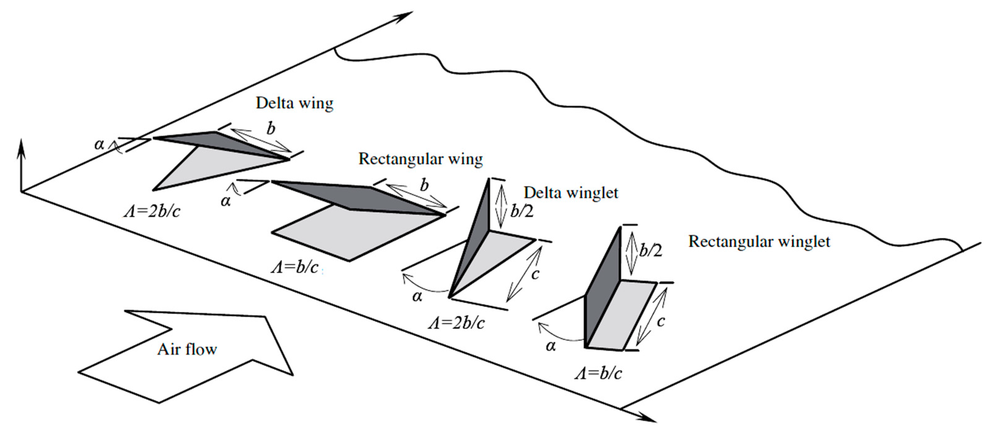
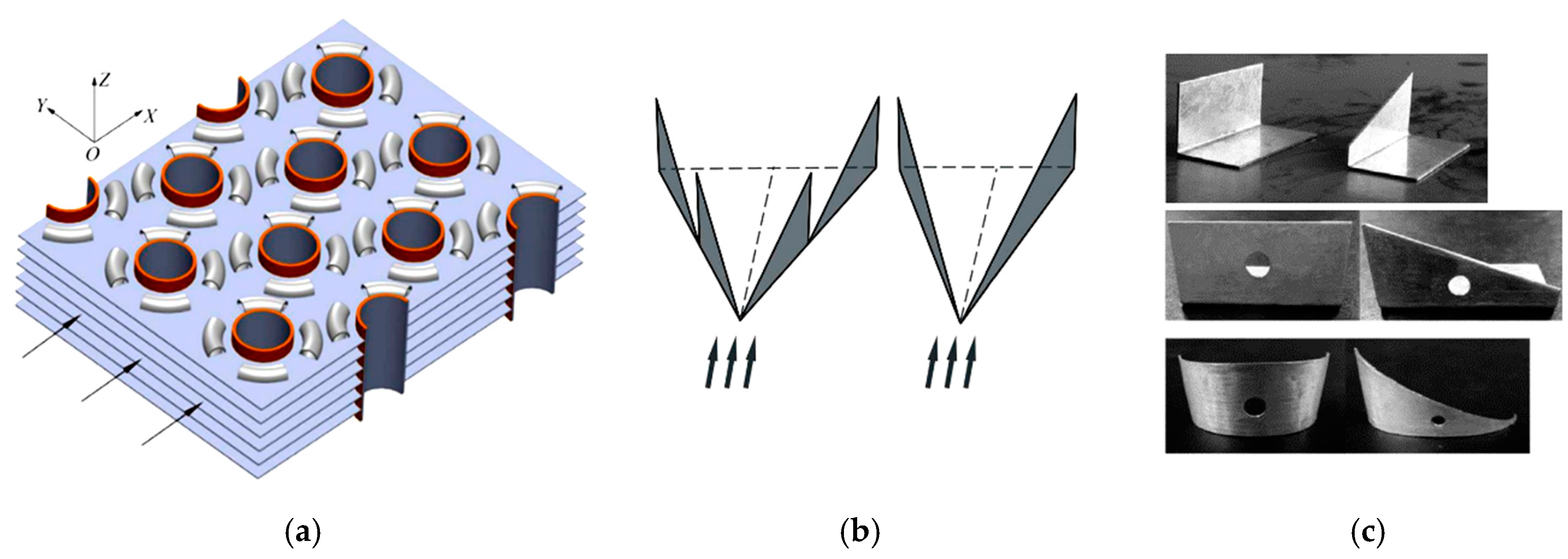
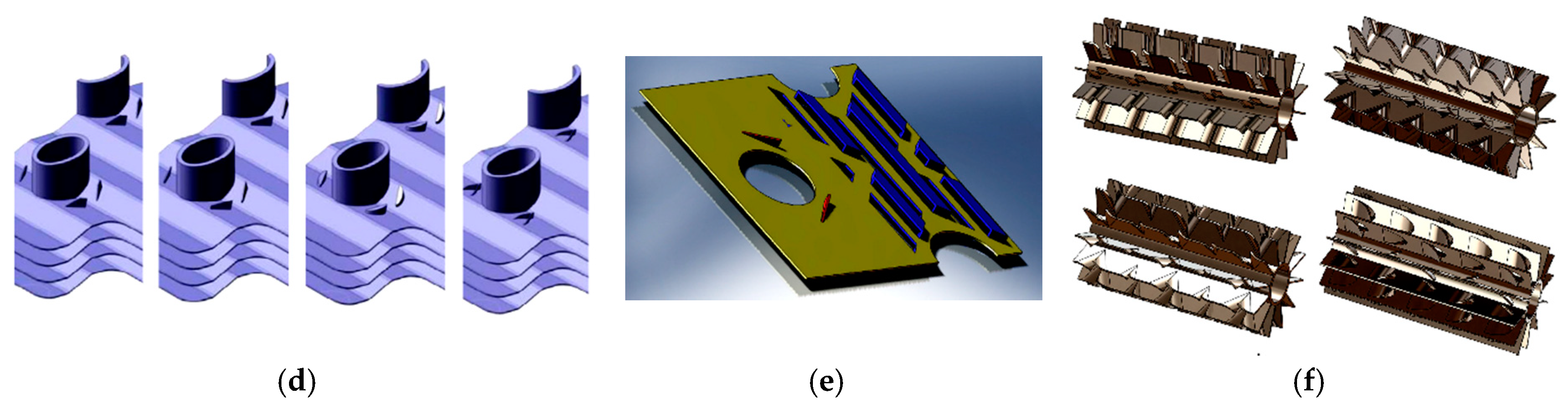
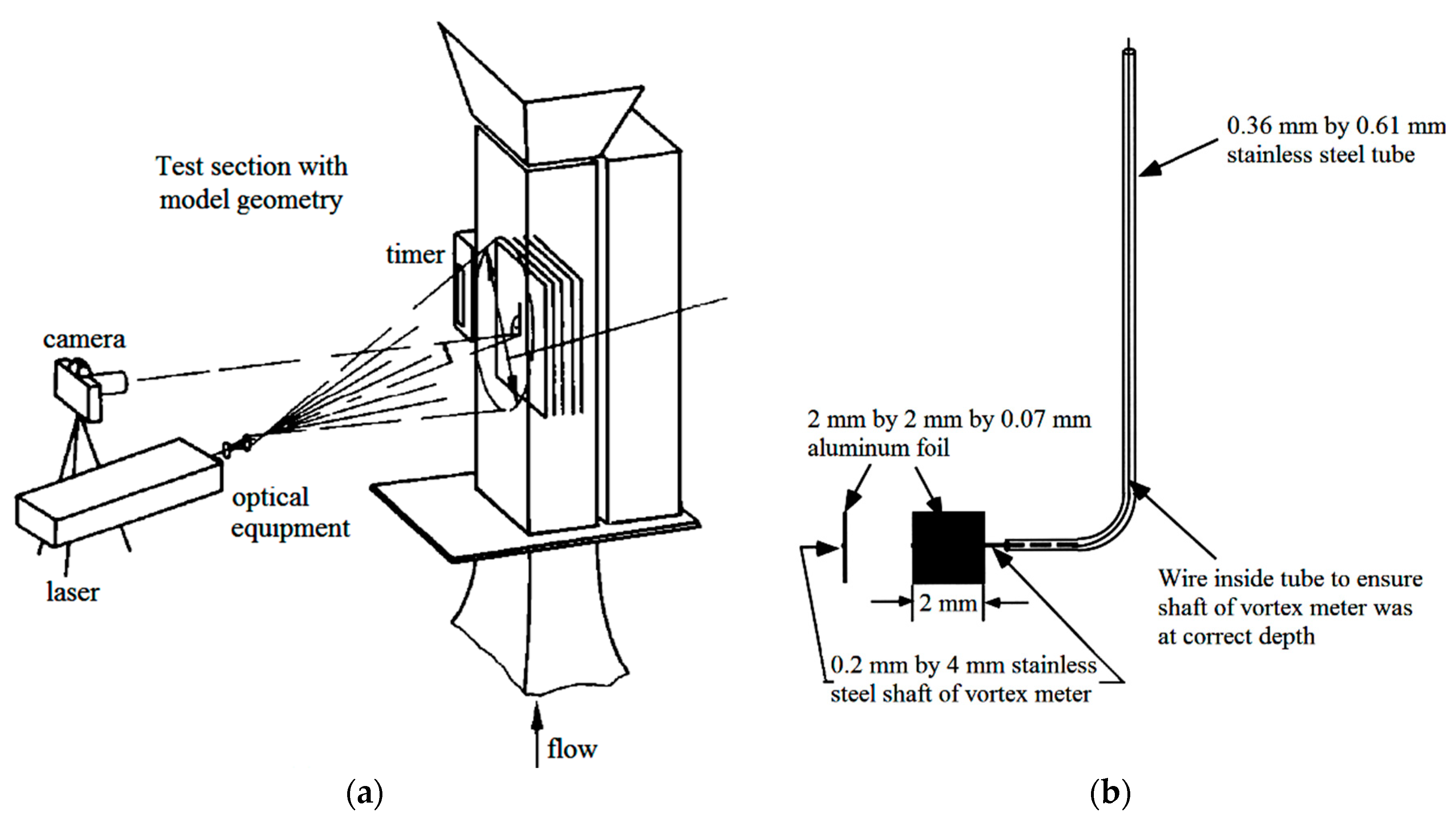
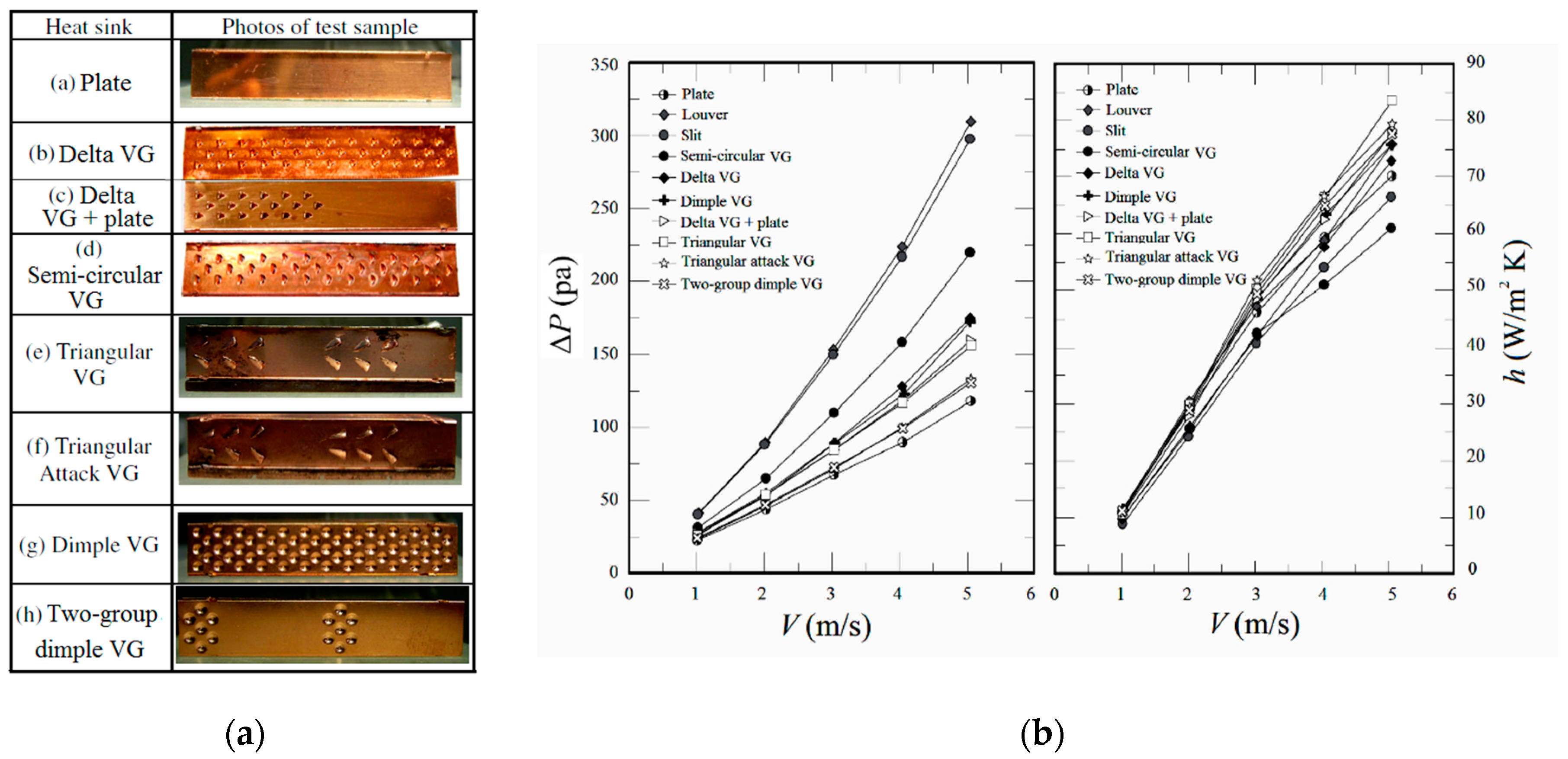
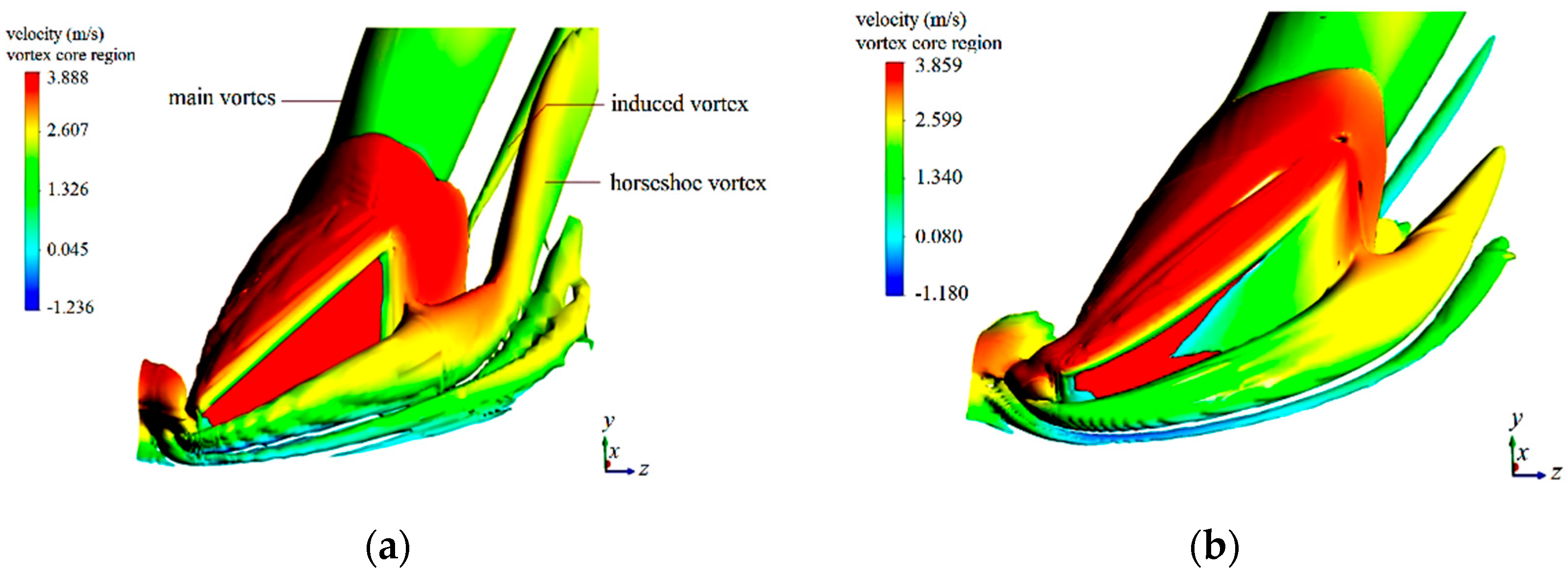
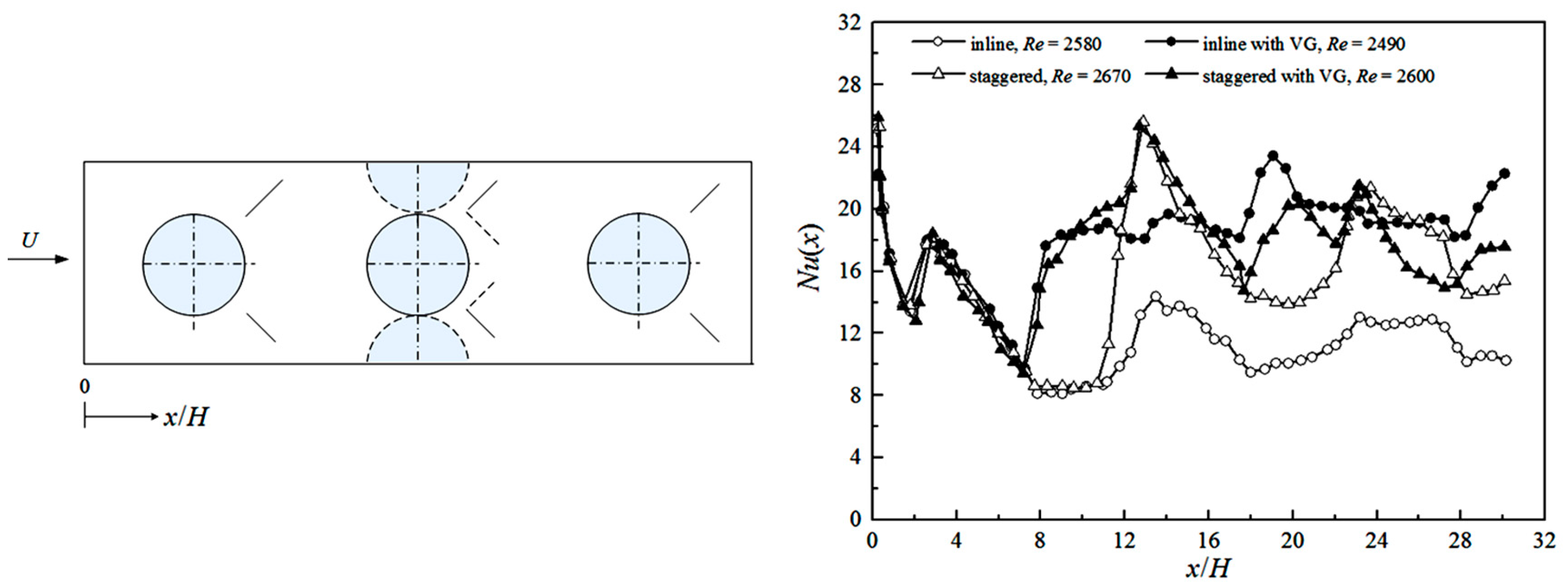
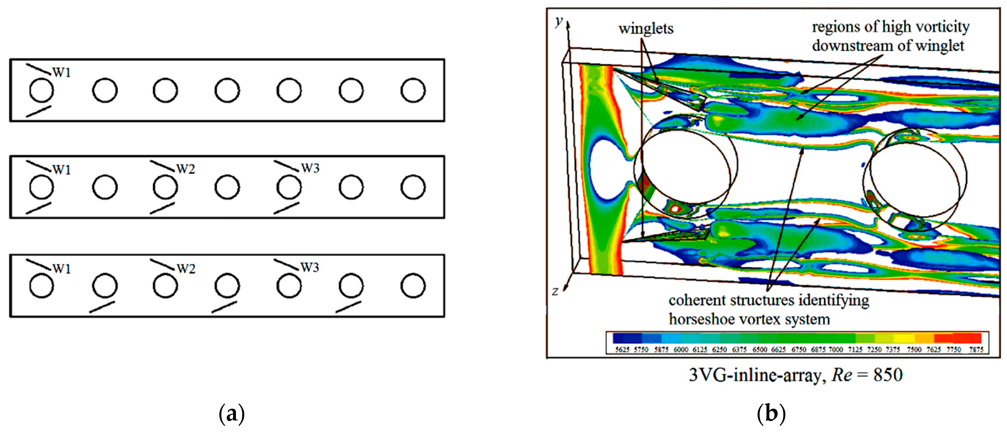
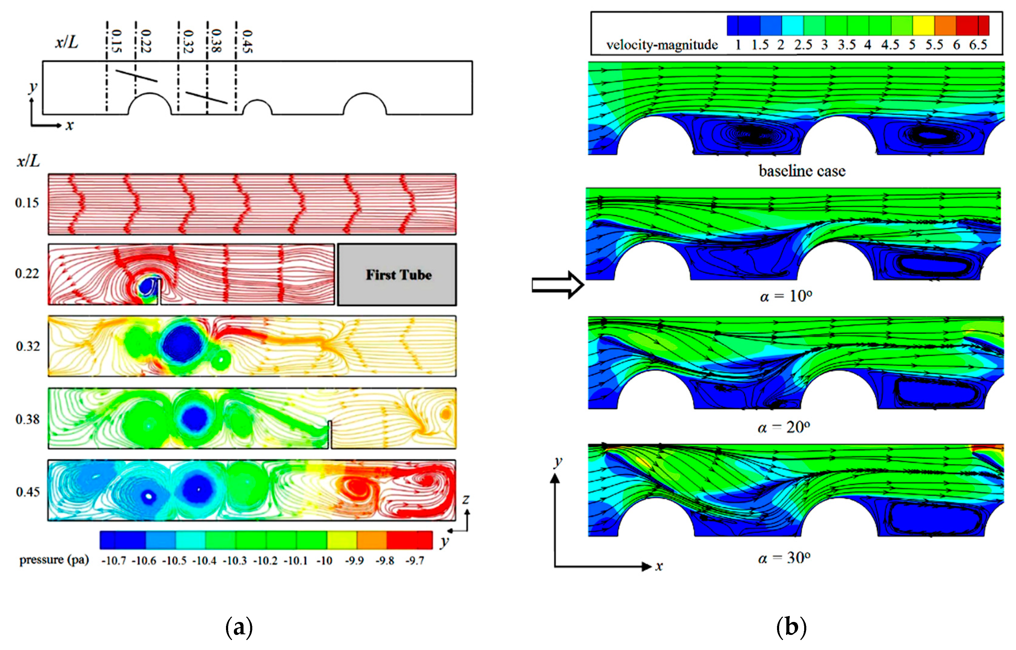
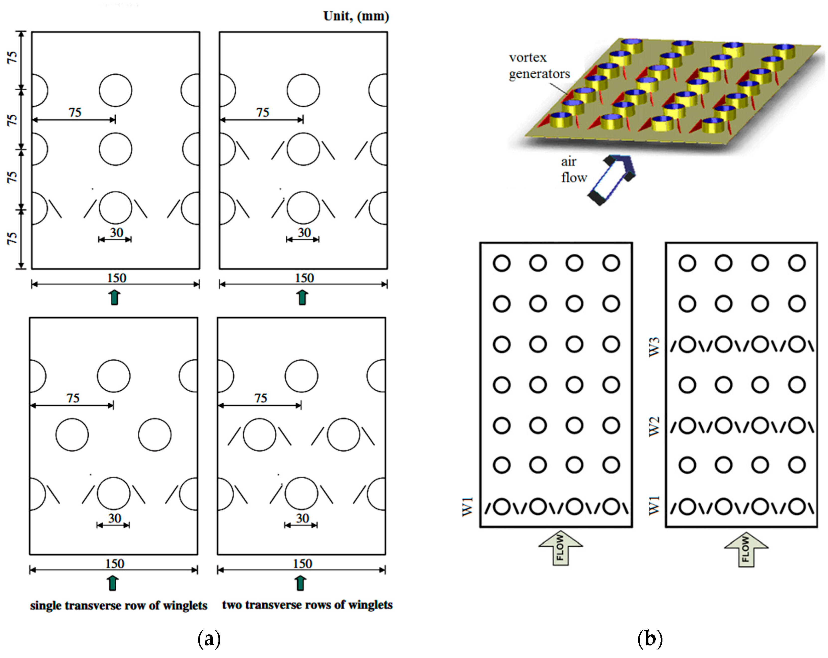
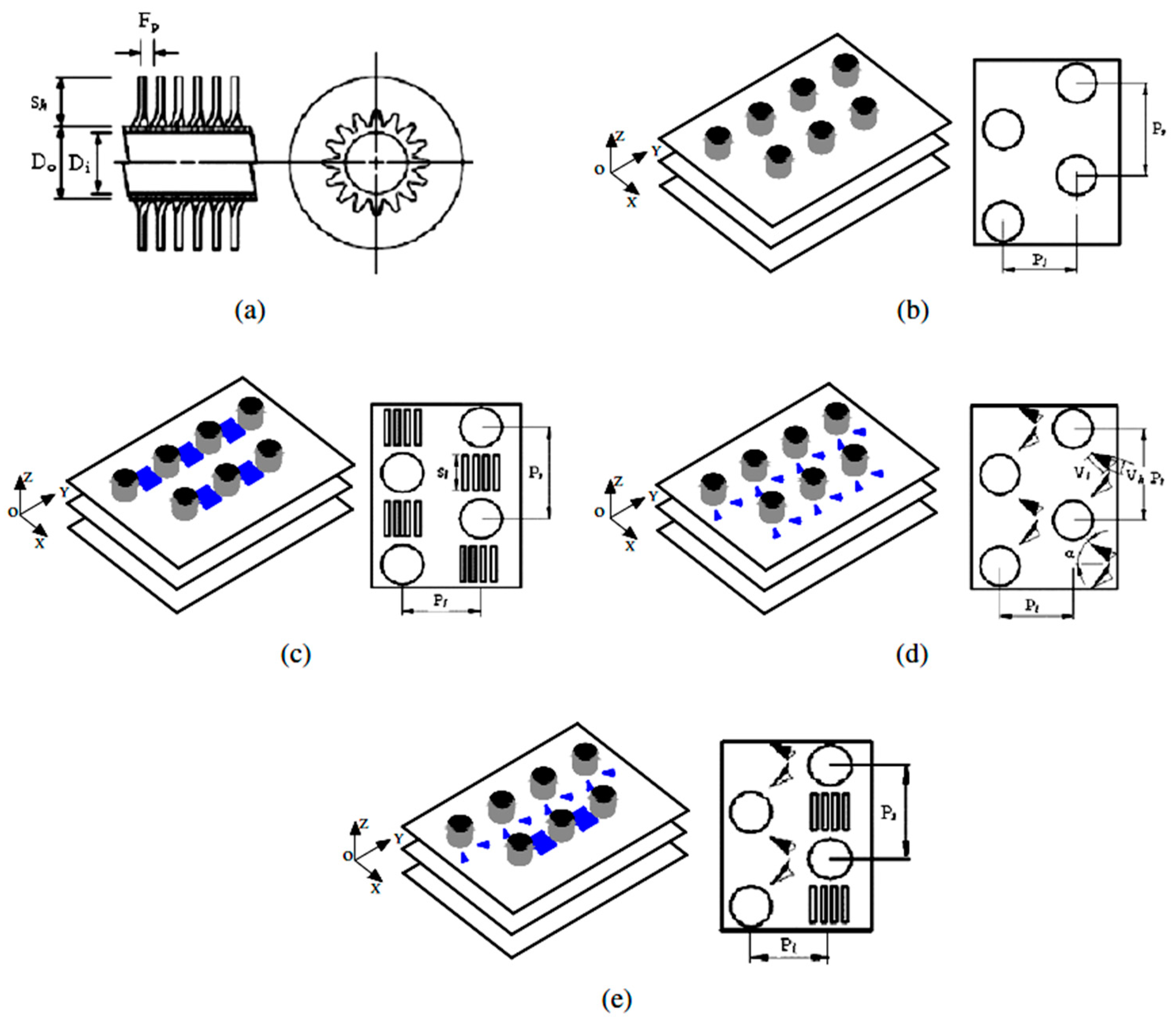
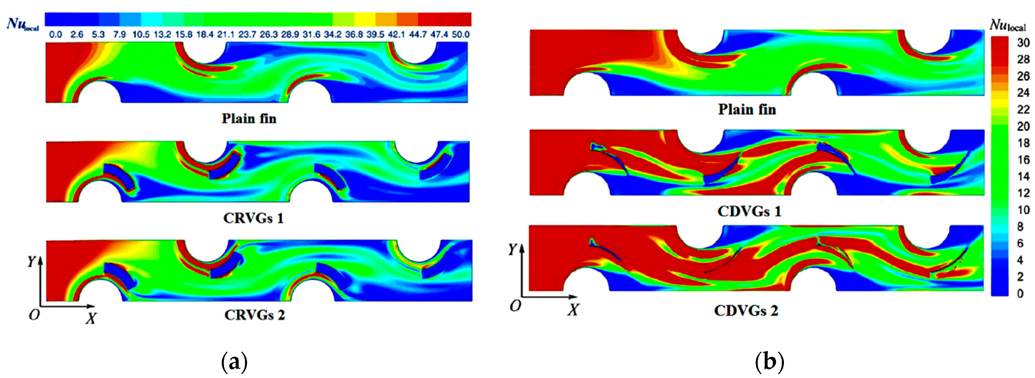
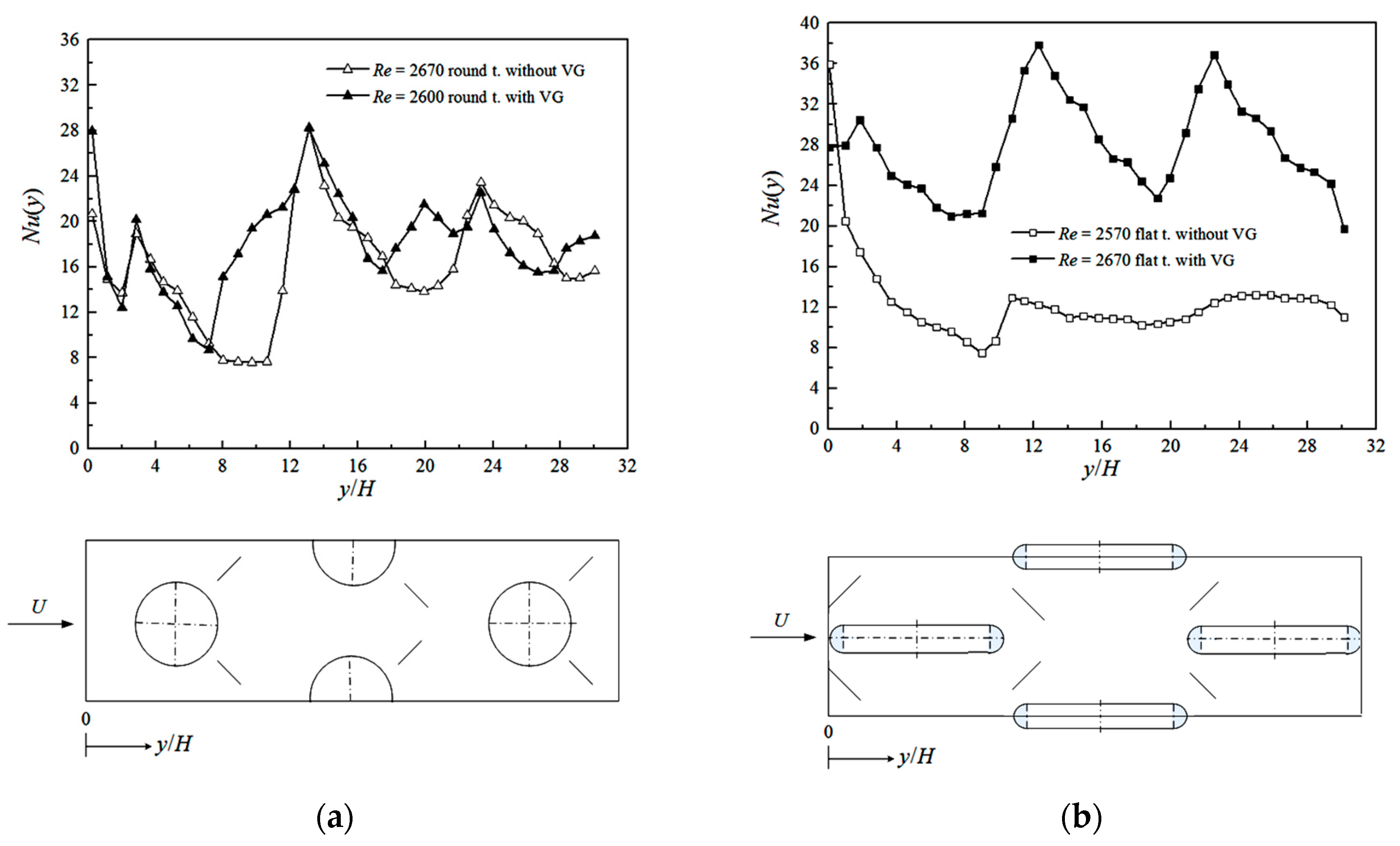
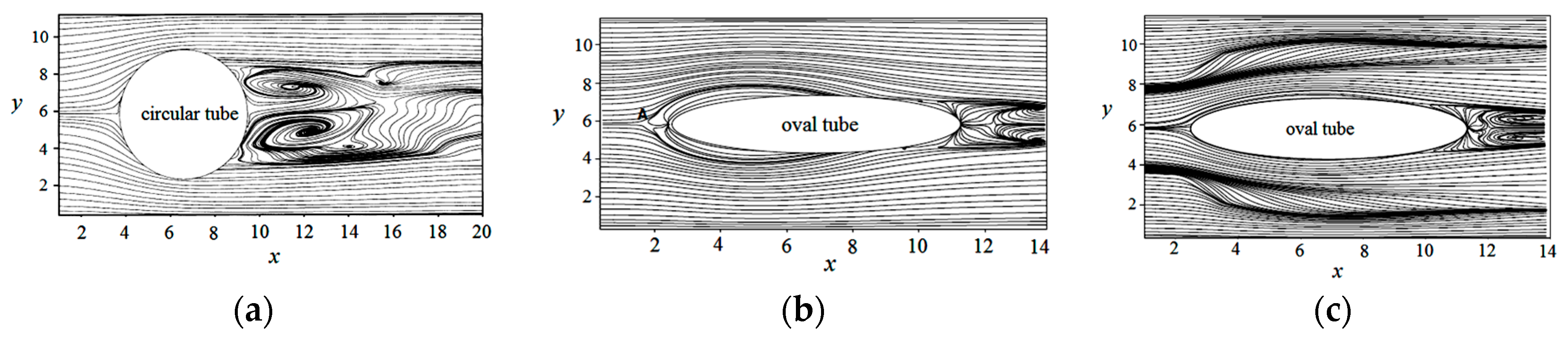
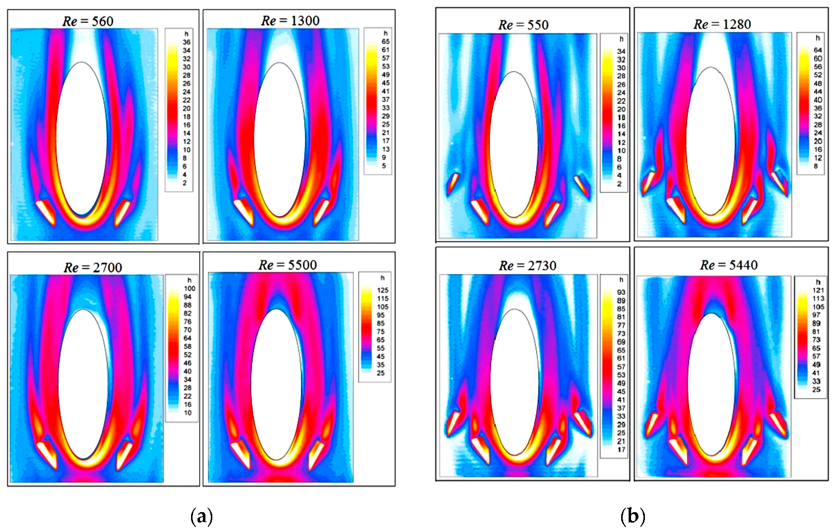
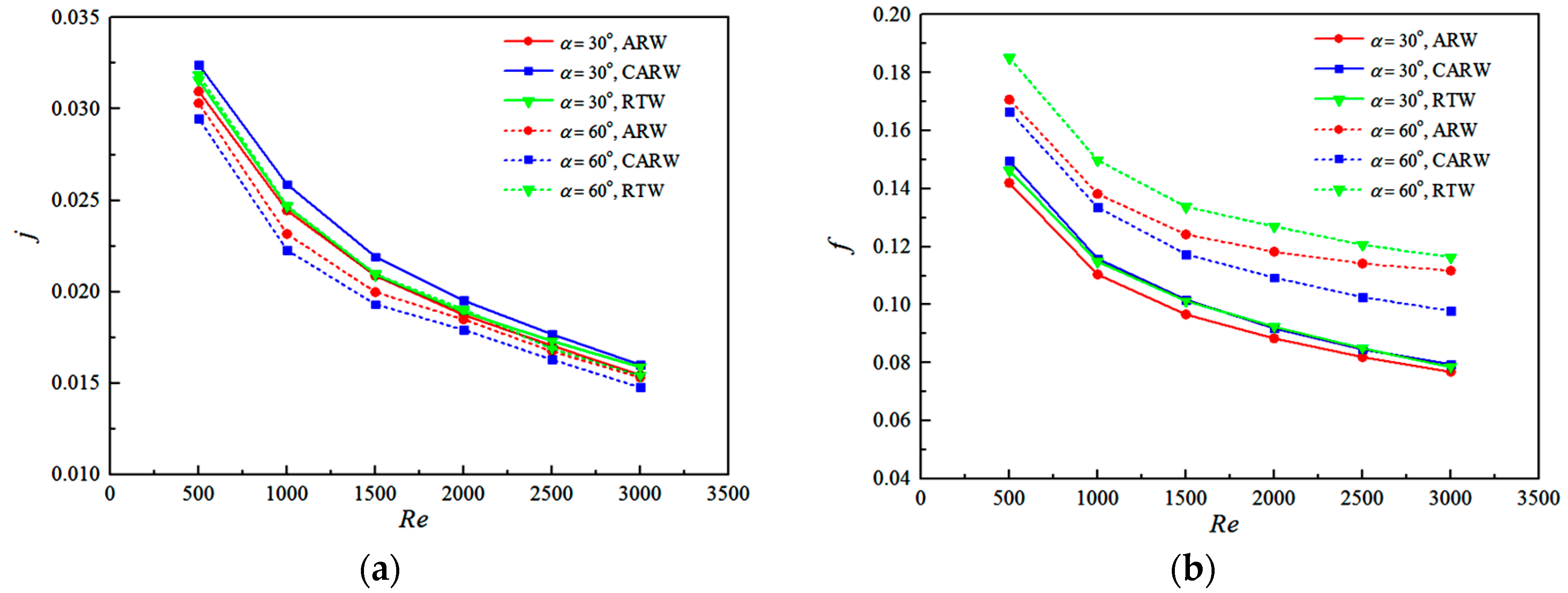
Table 1.
Representative experimental investigations of airside thermohydraulic performance with vortex generators on heat transfer surfaces.
Table 1.
Representative experimental investigations of airside thermohydraulic performance with vortex generators on heat transfer surfaces.
| Reference | Vortex Generators (VGs) | Re | Methodology | Measurement |
|---|---|---|---|---|
| Garimella and Eibeck [23] | Two different half-delta wings in a horizontal channel. | 700–5200 | An array of 30 heated copper elements mounted on the detachable hatch in six spanwise rows for heat transfer. | Heat transfer enhancement, pressure drop. |
| Fiebig et al. [24] | Delta and rectangular wings on a flat plate. | 1360–2270 | A laser light sheet used for the flow visualization, unsteady liquid crystal thermography to determine the local heat transfer coefficients. | Flow pattern, local heat transfer coefficient, drag coefficient, Colburn j-factor, normalized heat transfer enhancement. |
| Tiggelbeck et al. [25,26] | Single and double rows of half-delta wings on a flat plate. | 1600–8000 | Tracer particles of evaporating glycerine used for observations of the flow structure, laser light sheets to observe the visible flow field, a liquid crystal thermography used for local heat transfer measurements. | Flow pattern and vortex property, local Nu number, average Nu number and drag coefficient. |
| Fiebig et al. [27] | DWPs in a finned circular-tube heat exchanger. | 600–2700 | A hot-wire anemometer at 2 mm intervals to measure the axial velocity, a liquid crystal thermography used for local heat transfer measurements. | Nu number distribution, local Nu number, average Nu number and apparent friction factor. |
| Tiggelbeck et al. [28] | Delta wing, rectangular wing, DWPs and RWPs on a flat plate. | 2000–9000 | A thermochromic liquid crystal thermography to measure the local heat transfer on the wall. | Local Nu number. |
| Fiebig et al. [29] | DWPs in finned circular and flat-tube heat exchangers. | 600–3000 | A liquid crystal thermography used for local heat transfer measurements. | Nu number distribution, local Nu number, average Nu number and apparent friction factor. |
| Gentry and Jacobi [30] | Delta wings on a flat plate. | 600, 800, 1000 | A laser light sheet used for flow visualization, naphthalene sublimation experiments to provide convection coefficients. | Sherwood number, drag coefficient. |
| Kotcioğlu et al. [31] | RWPs on a flat plate. | 3000–30,000 | A smoke generator used for laminar main flow visualization in a Hele–Shaw apparatus. | Flow pattern, average Nu number and friction factor. |
| Wang et al. [6,9] | Interrupted annular and delta winglets in a finned circular-tube heat exchanger. | 500, 1500, 3300 | Water tunnel apparatus used to visualize the flow pattern, a dye-injection technique with a digital video camera used for the flow visualization. | Flow pattern. |
| Torii et al. [32,33,34] | DWPs in a finned circular-tube heat exchanger. | 350–2100 | A stainless steel ribbon heating screen uniformly spread over an entire cross section at the inlet of the test section to heat the flow quickly and uniformly. | Colburn j-factor, friction factor. |
| Gentry and Jacobi [35] | Delta wings on a flat plate. | 300–2000 | A laser light sheet used for flow visualization, naphthalene sublimation experiments to provide convection coefficients, a vane-type vortex meter and a potential-flow model with flow visualization to infer vortex strength. | Flow pattern, dimensionless vortex circulation, Sherwood number distribution, average Sherwood number, heat transfer enhancement, pressure-drop penalty. |
| Yoo et al. [36] | RWPs in a finned circular-tube heat exchanger. | 800–4500 | Naphthalene sublimation technique to measure local mass transfer coefficients, analogy equation between heat and mass transfer to calculate heat transfer coefficients. | Nu number distribution, local Nu number, average Nu number and apparent friction factor. |
| Yuan et al. [37] | RWPs on a flat plate. | 5000–47,000 | Twenty-five rows of copper-constantan thermocouple mounted uniformly in the flow direction to measure local heat transfer coefficients. | Local Nu number, average Nu number and friction factor, correlations for average Nu number and apparent Darcy friction factor. |
| Chen and Shu [38] | Delta wings on a flat plate. | 4430–11,820 | Laser Doppler velocimetry to characterize the flow structures and measure three-component mean and fluctuating velocity, 25 thermocouples mounted in the flow direction to measure the surface temperature. | Velocity structure, near-wall flow parameters, average Nu number. |
| Leu et al. [39] | RWPs in a finned circular-tube heat exchanger. | 400–3000 | Dye-injection technique with a digital video camera used for the flow visualization, infrared thermal camera to measure temperature distribution, a precision hot-wire instrument to measure inlet velocity. | Temperature field, Nu number distribution, average heat transfer coefficient and pressure drop. |
| O’Brien et al. [40] | DWPs in a finned oval-tube heat exchanger. | 600–6500 | A precision imaging infrared camera to measure the local fin surface temperature distributions, an inline precision mass flow meter to monitor the airflow rate. | Heat transfer coefficient distribution, average Nu number and friction factor. |
| Sommers and Jacobi [41] | Delta wings in a finned circular-tube heat exchanger. | 500–1300 | An upstream cooling coil and a controlled steam injection system to control the temperature and humidity of the air, hot-bulb anemometry to measure the airflow velocity. | Overall thermal resistance, pressure-drop penalty, Colburn j-factor, Fanning friction factor, volume goodness factor, average frost density with time. |
| Pesteei et al. [42] | DWPs in parallel plates with a single cylindrical obstacle. | 2250 | Total 23 thermocouples fitted on half section of the fin surface to measure the local temperature distribution. | Local heat transfer coefficient, average Nu number and apparent friction factor. |
| Shi et al. [43] | DWPs in a finned flat-tube heat exchanger. | <3000 | Naphthalene sublimation technique for heat–mass transfer analogy. | Nu number distribution, local Nu number, friction factor, JF factor. |
| Allison and Dally [44] | DWPs in a finned circular-tube heat exchanger. | 2600, 3400, 4600 | Dye-injection technique with a digital video camera used for the flow visualization. | Colburn j-factor, Fanning friction factor, JF factor. |
| Wang et al. [45] | RWPs on a flat plate. | 3000–20,000 | Deionized water as working fluid. | Local Nu number, average Nu number and friction factor, correlations for average Nu number and friction factor. |
| Joardar and Jacobi [46] | DWPs in a finned circular-tube heat exchanger. | 220–960 | An upstream cooling coil and a controlled steam injection system to control the temperature and humidity of the air, a static mixer at the fan outlet and a centrifugal mixer to ensure a thoroughly mixed flow of uniform temperature and humidity. | Average heat transfer coefficient, thermal resistance, pressure drop, Colburn j-factor, friction factor, volume goodness factor. |
| Tang et al. [47,48] | DWPs and mixed fins in a finned circular-tube heat exchanger. | 4000–10,000 | Steam-air system employed for the accomplishment of steam-to-air heat exchange, a Pitot-tube meter connected to an inclined draft gauges or U-tube water column manometer for measurement of the air flow rate. | Average Nu number and pressure drop, Colburn j-factor, friction factor, heat transfer performance comparison criteria, correlations of Nu number and friction factor. |
| Hernon and Patten [49] | DWPs on a flat plate. | A constant temperature anemometer system to measure mean and fluctuation velocities. | Time-averaged local velocity, boundary layer thickness. | |
| He et al. [17] | V type DWPs in a finned circular-tube heat exchanger. | 1400–3400 | A 6-junction, equally spaced thermocouple grid and another 12-junction grid used to detect the air temperatures at the inlet and downstream of the specimen, respectively. | Average heat transfer coefficient, pressure drop, Colburn j-factor, Fanning friction factor, area goodness and volume goodness factors. |
| Yang et al. [50] | Delta wings, semi-circular wings, triangular wings and dimple wings on a flat plate. | 120–600 | A multiple nozzle code tester to measure the air flowrate, an air straightener equalizer and a mixer avoid and minimize the effect of flow maldistribution. | Average heat transfer coefficient and pressure drop, Colburn j-factor, friction factor, inverse Graetz number. |
| Promvonge et al. [51,52] | Combined ribs and winglets in a triangular ribbed channel. | 5000–22,000 | A multiple nozzle code tester based on the ASHRAE 41.2 standard to measure the air flowrate, an air straightener equalizer and a mixer avoid and minimize the effect of flow maldistribution. | Average Nu number and friction factor, performance evaluation criteria. |
| Min et al. [53] | Modified RWPs on a flat plate. | 5000–17,500 | A hot-wire anemometer to measure the channel inlet velocity, an infrared imaging camera to obtain quantitative thermal visualization images, 54 thermocouples installed at the channel exits to measure the average outlet temperature, a PIV measurement with CCD camera and to generate glycerol particles for the flow visualization. | Average Nu number and friction factor, local Nu number, secondary flow vector distribution. |
| Aris et al. [54] | Delta wings in a finned circular-tube heat exchanger. | 330–960 | An orifice unit located after the fan to determine the air mass flow rate. | Average Nu number and Darcy friction factor. |
| Aris et al. [14] | Delta wings on a flat plate. | 1573–3712 | A 16-mm thick copper block heated by two cartridge heaters to obtain a uniform temperature condition, an infrared camera to acquire surface temperature distribution. | Local Nu number, average Nu number and apparent friction factor. |
| Wu and Tao [55] | Delta wings and punched holes on a flat plate. | 500–2000 | A thermocouple mesh with eight thermocouples to measure the nearly uniform inlet air temperature distribution, a thermocouples mesh with 16 thermocouples to measure the outlet temperature distribution, 16 thermocouples embedded in the upper and lower sheets to measure the wall temperature distribution. | Temperature distribution, average Nu number. |
| Zhou and Ye [18] | RWPs, TWPs, DWPs, CTWPs on a flat plate. | 700–26,800 | A thermocouple mesh with 12 T-type thermocouples to measure the outlet temperature distribution, 21 T-type thermocouples embedded in the copper plate to measure the wall temperature distribution. | Average Nu number and friction factor. |
| Wu et al. [56] | DWPs in a novel finned circular-tube heat exchanger. | A nozzle flow meter to measure the air flowrate. | Average heat transfer coefficient and pressure drop. | |
| Zhou and Feng [19] | RWPs, TWPs, DWPs, CTWPs with or without holes on winglet on a flat plate. | 650–21,000 | A thermocouple mesh with 12 T-type thermocouples to measure the outlet temperature distribution, 21 T-type thermocouples embedded in the copper plate to measure the wall temperature distribution. | Average Nu number and Darcy friction factor. |
| Wang et al. [57] | Semi-dimple winglet pairs in plain or louvre finned circular-tube heat exchanger. | A multiple nozzle code tester to measure the air flowrate, an air straightener equalizer and a mixer avoid and minimize the effect of flow maldistribution. | Average heat transfer coefficient and pressure drop. | |
| Abdelatie et al. [58] | RWPs in a wing-shaped-tubes-bundle heat exchanger. | 1850–9700 | Eight thermocouples on two grids at the entrance and the exit to measure inlet and outlet air average temperatures, an alcohol thermometer with wet wick surrounded bulb to measure the wet bulb temperatures at the inlet and the exit. | Average Nu number and drag coefficient. |
| Wu et al. [59] | Curved DWPs in a finned circular-tube heat exchanger. | 500–4200 | Eight thermocouples on two grids at the entrance and the exit to measure inlet and outlet air temperatures, an alcohol thermometer with wet wick surrounded bulb to measure the wet bulb temperatures at the inlet and the exit. | Average Nu number and friction factor, average heat transfer coefficient and pressure drop, JF factor, correlations for average Nu number and Darcy friction factor. |
DWPs: delta winglet pairs; RWPs: rectangular winglet pairs; TWPs: trapezoidal winglet pairs; CTWPs: curved trapezoidal winglet pairs.
Table 2.
Representative numerical studies of airside thermohydraulic performance with vortex generators on heat transfer surfaces.
Table 2.
Representative numerical studies of airside thermohydraulic performance with vortex generators on heat transfer surfaces.
| Reference | VGs | Re | Methodology | Measurement |
|---|---|---|---|---|
| Fiebig et al. [62] | Delta winglets or delta wings on a flat plate. | 500–2000 | SOLA algorithm, unsteady laminar model, incompressible flow, hydrodynamically developed inlet velocity and constant inlet temperature. | Velocity structure, temperature field. |
| Biswas et al. [63] | Delta wings on a flat plate. | 500–1815 | Modified MAC algorithm, unsteady laminar model, uniform inlet velocity and constant inlet temperature. | Velocity structure, temperature field, local Nu number and friction factor. |
| Biswas et al. [64] | Delta wings and punched holes on a flat plate. | 500–1815 | Modified MAC algorithm, unsteady laminar model, uniform inlet velocity and constant inlet temperature. | Velocity structure, temperature field, local Nu number and friction factor. |
| Zhu et al. [65] | DWPs on a flat plate. | 67,000 | SOLA algorithm, unsteady k–ε turbulence model, incompressible flow, inlet velocity component profile from experiment. | Velocity structure. |
| Zhu et al. [66] | Delta wings, rectangular wings, DWPs and RWPs on a flat plate. | 50,000 | SOLA algorithm, unsteady k–ε turbulence model, incompressible flow, hydrodynamically developed inlet velocity and constant inlet temperature. | Velocity structure, temperature field, local Nu number, average Nu number and apparent friction factor. |
| Biswas et al. [67] | DWPs in a circular-tube heat exchanger. | 500–1000 | Modified MAC algorithm, unsteady laminar model, fully developed inlet velocity and constant inlet temperature. | Velocity structure, temperature field, local Nu number. |
| Biswas et al. [68] | Delta wings and DWPs on a flat plate. | 500–3000 | Modified MAC algorithm, unsteady laminar model, incompressible flow, uniform inlet velocity and constant inlet temperature. | Velocity structure, local Nu number and skin friction coefficient. |
| Deb et al. [69] | DWPs on a flat plate. | 400–1000 | Modified MAC algorithm, unsteady laminar model and k–ε turbulence model, incompressible flow. | Velocity structure, local Nu number and skin friction coefficient. |
| Biswas et al. [70] | Delta winglets on a flat plate. | 1580 | Modified MAC algorithm, unsteady laminar model, fully developed inlet velocity and constant inlet temperature. | Velocity structure, local Nu number and quality factor. |
| Chen et al. [71] | Punched delta winglets in a finned oval-tube heat exchanger. | 300 | Steady laminar model, incompressible flow, fully developed inlet velocity and constant inlet temperature. | Velocity structure, temperature field, pressure distributions, local Nu number and pressure drop. |
| Vasudevan et al. [72] | Triangular duct with delta winglet. | 100, 200 | Steady laminar model, incompressible flow, uniform inlet velocity and constant inlet temperature. | Velocity structure, temperature field, local Nu number. |
| Sohankar and Davidson [73] | Inclined block shapes on a flat plate. | 400–1500 | Unsteady laminar incompressible flow, uniform inlet velocity and constant inlet temperature. Second-order central or third-order QUICK differencing scheme to discretize the convective term and second-order central differencing scheme to discretize the others. | Velocity structures, Nu number distribution, local Nu number, average Nu number and apparent friction factor. |
| Tiwari et al. [74] | DWPs in a finned oval-tube heat exchanger. | 500, 1000, 1500 | Steady laminar model, uniform inlet velocity and constant inlet temperature. Finite-volume formulation to discretize the governing equations. | Velocity structures, Nu number distribution, local Nu number. |
| Prabhakar et al. [75] | DWPs in a finned oval-tube heat exchanger. | 1300 | Steady laminar model, incompressible flow, uniform inlet velocity and constant inlet temperature. Finite-volume formulation to discretize the governing equations. | Velocity structures, Nu number distribution, local Nu number. |
| Jain et al. [76] | DWPs in a finned circular-tube heat exchanger. | 1000 | Steady laminar model, incompressible flow, uniform inlet velocity and constant inlet temperature. Finite-volume formulation to discretize the governing equations. | Velocity structures, Nu number distribution, local Nu number. |
| Leu et al. [39] | RWPs in a finned circular-tube heat exchanger. | 400–3000 | Steady k–ε turbulence model, incompressible flow, uniform inlet velocity and constant inlet temperature. | Temperature field, Nu number distribution, average heat transfer coefficient and Fanning friction factor. |
| Joardar and Jacobi [77] | DWPs in a finned circular-tube heat exchanger. | 330–850 | FLUENT solver, unsteady laminar model, incompressible flow, uniform inlet velocity and constant inlet temperature. Finite-volume formulation using a fully implicit higher-order upwind differencing scheme to discretize the governing equations, SIMPLEC algorithm to couple the pressure and velocity. | Velocity structure, heat flux distribution, local heat flux, average heat flux and friction factor. |
| Wu and Tao [78] | DWPs in a finned circular-tube heat exchanger. | 800–2000 | FLUENT solver, steady laminar model, incompressible flow, uniform inlet velocity and constant inlet temperature. Second upwind scheme to discretize the convection term, SIMPLEC algorithm to couple the pressure and velocity. | Velocity structure, temperature field, average Nu number, synergy angle. |
| Wu and Tao [79,80] | Rectangular winglet in a rectangular channel. | 800–3000 | FLUENT solver, steady laminar model, incompressible flow, uniform inlet velocity and constant inlet temperature. Second-order upwind scheme to discretize the convective term, central difference scheme to discretize the diffusion term, SIMPLEC algorithm to couple the pressure and velocity. | Velocity structure, temperature field, local pressure and Nu number, average Nu number and Fanning friction factor. |
| Song et al. [81] | DWPs in a finned flat-tube heat exchanger. | 200–1900 | Steady laminar model, incompressible flow, periodicity conditions in the inlet and exit. Power scheme to discretize the convective terms, SIMPLE algorithm to couple the velocity and pressure. | Nu number distribution, local Nu number, average Nu number and friction factor. |
| Chang et al. [82] | DWPs in a finned flat-tube heat exchanger. | 300–1700 | FLUENT solver, steady laminar model, incompressible flow, uniform inlet velocity and constant inlet temperature. Power scheme to discretize the convective terms, SIMPLE algorithm to couple the velocity and pressure. | Absolute vorticity flux and Nu number distributions, local absolute vorticity flux and Nu number, average Nu number and friction factor. |
| Tang et al. [48] | DWPs in a finned circular-tube heat exchanger. | 4000–100,000 | FLUENT solver, standard k–ε turbulence model, incompressible flow, uniform inlet velocity and constant inlet temperature. QUICK scheme to discretize the convection terms and central finite differencing to discretize the diffusion terms, SIMPLEC algorithm to solve the pressure field. | Correlations of Nu number and friction factor. |
| Tian et al. [4] | DWPs in a triangular wavy fin-tube heat exchanger. | 500–5000 | FLUENT solver, steady RNG k–ε turbulence model, incompressible flow, uniform inlet velocity and constant inlet temperature. Central difference scheme to discretize the diffusion term, and the SIMPLEC algorithm to couple the pressure and velocity. | Velocity structure, temperature field, local heat transfer coefficient, average Nu number and friction factor, area goodness and volume goodness factors. |
| Tian et al. [83] | Delta winglets on a flat plate. | 470–1700 | FLUENT solver, steady laminar model, incompressible flow, uniform inlet velocity and constant inlet temperature. SIMPLEC algorithm to couple the pressure and velocity, second-order upwind scheme to discretize the convection terms, central difference scheme to discretize the diffusion term. | Velocity structure, temperature field, local pressure coefficient, heat transfer coefficient, average Nu number and friction factor, intersection angle. |
| Chu et al. [84] | RWPs in a finned circular-tube heat exchanger. | 500–880 | FLUENT solver, steady laminar model, incompressible flow, uniform inlet velocity and constant inlet temperature. Second-order upwind scheme to discretize the governing equations, SIMPLE algorithm to couple the pressure and velocity. | Velocity structure, temperature field, local Nu number, average Nu number and friction factor, intersection angle. |
| Onishi et al. [85] | Rectangular winglets in a finless flat-tube heat exchanger. | 710–2130 | FLUENT solver, unsteady laminar model, uniform inlet velocity and constant inlet temperature. QUICK scheme to discretize the convection terms and central finite differencing to discretize the diffusion terms, SIMPLE algorithm to solve the pressure field. | Velocity structure, temperature field, average Nu number and pressure coefficient, area goodness and volume goodness factors. |
| Lei et al. [86] | DWPs in a finned circular-tube heat exchanger. | 600–2600 | FLUENT solver, steady laminar model, incompressible flow, uniform inlet velocity and constant inlet temperature. SIMPLEC algorithm to couple the pressure and velocity, QUICK scheme with third-order precision to discretize the convection terms. | Velocity structure, temperature field, local Nu number, average heat transfer coefficient and friction factor, intersection angle. |
| Zeng et al. [87] | DWPs in a finned circular-tube heat exchanger. | 4200–12,200 | FLUENT solver, steady k–ε turbulence model, incompressible flow, uniform inlet velocity and constant inlet temperature. SIMPLEC algorithm to couple the pressure and velocity. | Average Nu number and Darcy friction factor, performance evaluation criteria. |
| Lemouedda et al. [88] | DWPs in a finned circular-tube heat exchanger. | 200–1200 | STAR-CD solver, steady laminar model, incompressible flow, uniform inlet velocity and constant inlet temperature. A central scheme of second-order accuracy for the spatial discretization of the computational domain. | Velocity structure, temperature field, heat transfer rate, power input. |
| Aris et al. [54] | Delta wings in a finned circular-tube heat exchanger. | 300 | Steady laminar model, uniform inlet velocity and constant inlet temperature. | Temperature field, local Nu number. |
| Wu and Tao [89] | DWPs in a novel finned circular-tube heat exchanger. | 800–2000 | FLUENT solver, steady laminar model, uniform inlet velocity and constant inlet temperature. Second-order upwind scheme to discretize the convective terms, SIMPLEC algorithm to couple the pressure and velocity. | Average Nu number and pressure drop. |
| Hwang et al. [90] | DWPs in a finned circular-tube heat exchanger. | 130–5180 | RNG k–ε turbulence model, incompressible flow, uniform inlet velocity and constant inlet temperature. | Velocity structure, pressure distribution, temperature field, Colburn j-factor, friction factor. |
| Pal et al. [91] | DWPs in a finned circular-tube heat exchanger. | <800 | FLUENT solver, steady laminar model, incompressible flow, uniform inlet velocity and constant inlet temperature. | Velocity structure, temperature field, local Nu number, area goodness factor. |
| He et al. [92] | Punched winglet pairs in a finned circular-tube heat exchanger. | 600–2600 | FLUENT solver, steady laminar model, incompressible flow, uniform inlet velocity and constant inlet temperature. | Velocity structure, local Nu number, average heat transfer coefficient and pressure drop, area goodness and volume goodness factors. |
| He et al. [93] | RWPs in a finned circular-tube heat exchanger. | 550–880 | FLUENT solver, steady laminar model, incompressible flow, uniform inlet velocity and constant inlet temperature. Second-order upwind scheme to discretize the convective terms, SIMPLE algorithm to couple the pressure and velocity. | Velocity structure, temperature field, average heat transfer coefficient and pressure drop, overall performance. |
| Sinha et al. [94] | DWPs on a flat plate. | 250–1580 | Modified MAC algorithm, laminar model, fully developed inlet velocity profile and constant inlet temperature. | Velocity structure, temperature field, local Nu number, overall performance. |
| Huisseune et al. [95] | DWPs in a louvred-fin-tube heat exchanger. | 220–915 | FLUENT solver, steady laminar model, incompressible flow, uniform inlet velocity and constant inlet temperature. SIMPLE algorithm to implement the coupling between pressure and velocity, second-order upwind scheme to discretize the convection terms, central difference scheme to discretize the diffusion term. | Velocity structure, Colburn j-factor, Fanning friction factor. |
| Jang et al. [96] | Pairs of inclined block-shape VGs in a finned circular-tube heat exchanger. | 400–1200 | FLUENT solver, steady laminar model, incompressible flow, uniform inlet velocity and constant inlet temperature. Third-order upwind scheme to model the convective terms, second-order central difference schemes to discretize the viscous and source terms. | Velocity structure, temperature field, Colburn j-factor, Fanning friction factor. |
| Hu et al. [97] | DWPs in a finned circular-tube heat exchanger. | 200–1900 | Laminar model, incompressible flow, uniform inlet velocity and constant inlet temperature. A control volume to integrate the governing equations, power scheme approximation to discretize the convective terms, second-order central difference scheme to discretize the diffusion terms, SIMPLE algorithm to couple the velocity and pressure. | Local heat transfer coefficient and Nu number, average Nu number and friction factor, secondary flow intensity. |
| Song and Wang [98] | DWPs in a finned flat-tube heat exchanger. | 200–1600 | Steady laminar model, incompressible flow, periodical fully developed heat transfer and fluid flow conditions. Power scheme, and central difference to discretize the convective and diffusion terms, SIMPLE algorithm to couple the velocity and pressure. | Local Nu number and absolute vorticity flux, average Nu number and friction factor. |
| Lotfi et al. [20] | DWPs in a smooth wavy fin elliptical-tube heat exchanger. | 500–3000 | SST k–ε turbulence model, incompressible flow, uniform inlet velocity and constant inlet temperature. | Nu numbe distribution, average Nu number and friction factor, Colburn j-factor, area goodness and volume goodness factors. |
| Saha et al. [99] | DWPs and RWPs on a flat plate. | 50–200 | Modified MAC algorithm, unsteady laminar model, and incompressible flow, periodic boundary conditions for both inlet velocity and temperature. | Velocity structure, temperature field, Nu number distribution, local Nu number and frictional loss, average Nu number and friction factor. |
| Gholami et al. [100] | Wavy RWPs in a finned circular-tube heat exchanger. | 400–800 | FLUENT solver, steady laminar model, incompressible flow, uniform inlet velocity and constant inlet temperature. | Velocity structure, pressure distribution, temperature field, average Nu number and friction factor. |
| Zhao et al. [101] | RWPs in an H-type finned oval-tube heat exchanger. | 22,504–40,509 | RNG k–ε turbulence model, incompressible flow, uniform inlet velocity and constant inlet temperature. | Velocity structure, temperature field, average Nu number, performance evaluation criteria. |
| Wu et al. [22] | DWPs in a slit finned circular-tube heat exchanger. | 304–2130 | Steady laminar model, incompressible flow, uniform inlet velocity and constant inlet temperature. | Velocity structure, temperature field, average Nu number and friction factor, JF factor, field synergy angle, equivalent thermal resistance. |
| Lin and Wang [102] | DWPs in a finned flat-tube heat exchanger. | 1300–2400 | Steady laminar model, incompressible flow, uniform inlet velocity and constant inlet temperature. Control volume method, a stability-guaranteed second-order difference scheme and a second-order central difference scheme respectively to discretize the governing equations, the convective terms, and the viscous terms. | Velocity structure, average Nu number and friction factor, local integral mean main flow velocity. |
| Lin et al. [15] | Interrupted annular groove fins in a finned circular-tube heat exchanger. | 600–2500 | Steady laminar model, incompressible flow, uniform inlet velocity and constant inlet temperature. Control volume method, a stability-guaranteed second-order difference scheme and a second-order central difference scheme respectively to discretize the governing equations, the convective terms and the viscous terms. | Velocity structure, average Nu number and friction factor, local integral mean main flow velocity. |
| Gong et al. [16] | Curved RWPs in a finned circular-tube heat exchanger. | 800–3000 | FLUENT solver, steady laminar model, incompressible flow, uniform inlet velocity and constant inlet temperature. | Velocity structure, Nu number distribution, average Nu number and friction factor, JF factor. |
| Behfard and Sohankar [103] | DWPs in a finned circular-tube heat exchanger. | 1000 | FLUENT solver, steady SST k–ε turbulence model, uniform inlet velocity and constant inlet temperature. Second-order upwind scheme to discretize the convective terms, SIMPLE algorithm to couple the pressure and velocity. | Velocity structure, temperature field, local pressure, average Nu number and Fanning friction factor, performance evaluation criteria. |
| Lin et al. [104] | Curved DWPs in a finned circular-tube heat exchanger. | 1100–3000 | Steady laminar model, incompressible flow, uniform inlet velocity and constant inlet temperature. Control volume method to discretize the governing equations. Second-order central difference scheme employed for the viscous terms. | Velocity structure, Nu number distribution, local intensity of secondary flow and Nu number, average Nu number and friction factor, JF factor. |
| Lotfi et al. [21] | RTW, ARW, CARW and WW in a wavy fin elliptical-tube heat exchanger. | 500–3000 | CFX solver, steady SST k–ε turbulence model, uniform inlet velocity and constant inlet temperature. | Velocity structure, temperature field, average Nu number, synergy angle. |
| Sinha et al. [105] | RWPs in a finned circular-tube heat exchanger. | 250–1500 | FLUENT solver, steady laminar model, fully developed velocity profile for the axial inlet velocity, finite-volume scheme. SIMPLE algorithm to couple the pressure and velocity, second-order upwind scheme to discretize the convection terms, central difference scheme to discretize the diffusion terms. | Velocity structure, temperature field, local Nu number, Fanning friction factor, quality factor. |
| Oneissi et al. [106] | DWPs on a flat plate. | 270–30,000 | FLUENT solver, steady laminar and SST k–ε turbulence model, uniform inlet velocity and constant inlet temperature. | Velocity structure, local Nu number, Fanning friction factor, vorticity property. |
| Esmaeilzadeh et al. [107] | TWPs and curved TWPs on a flat plate. | 7000–35,000 | FLUENT solver, steady Reynolds stress turbulence model, incompressible flow, uniform inlet velocity and constant inlet temperature. SIMPLEC algorithm to couple the pressure and velocity. | Velocity structure, local heat transfer coefficient, average Nu number and friction factor, overall performance. |
| Abdelatie et al. [58] | RWPs in a wing-shaped tubes-bundle heat exchanger. | 1850–9700 | RNG k–ε turbulence model, incompressible flow, uniform inlet velocity and constant inlet temperature. SIMPLE pressure-based solution algorithm to implement the velocity–pressure coupling. | Average Nu number and friction factor, heat transfer effectiveness, area goodness factor and efficiency index. |
RTW: rectangular trapezoidal winglet; ARW: angle rectangular winglet; CARW: curved angle rectangular winglet; WW: wheeler wishbone.
© 2018 by the authors. Licensee MDPI, Basel, Switzerland. This article is an open access article distributed under the terms and conditions of the Creative Commons Attribution (CC BY) license (http://creativecommons.org/licenses/by/4.0/).
Share and Cite
MDPI and ACS Style
Chai, L.; Tassou, S.A. A Review of Airside Heat Transfer Augmentation with Vortex Generators on Heat Transfer Surface. Energies 2018, 11, 2737. https://doi.org/10.3390/en11102737
AMA Style
Chai L, Tassou SA. A Review of Airside Heat Transfer Augmentation with Vortex Generators on Heat Transfer Surface. Energies. 2018; 11(10):2737. https://doi.org/10.3390/en11102737
Chicago/Turabian StyleChai, Lei, and Savvas A. Tassou. 2018. "A Review of Airside Heat Transfer Augmentation with Vortex Generators on Heat Transfer Surface" Energies 11, no. 10: 2737. https://doi.org/10.3390/en11102737
Note that from the first issue of 2016, this journal uses article numbers instead of page numbers. See further details here.