Article

Compound Heat Transfer Enhancement of Wavy Fin-and-Tube Heat Exchangers through Boundary Layer Restarting and Swirled Flow

1
Department of Mechanical and Aerospace Engineering, Malek-Ashtar University of Technology, Shahin-shahr, P.O. Box 83145/115, Isfahan, Iran
2
Department of Mechanics, Marvdasht Branch, Islamic Azad University, Marvdasht 73711-13119, Iran
3
Green Energy & Environment Research Laboratories, Industrial Technology Research Institute, Hsinchu 310, Taiwan
4
Department of Mechanical Engineering, National Chiao Tung University, EE474, 1001 University Road, Hsinchu 300, Taiwan
*
Author to whom correspondence should be addressed.
Energies 2018, 11(8), 1959; https://doi.org/10.3390/en11081959
Submission received: 3 July 2018 / Revised: 21 July 2018 / Accepted: 24 July 2018 / Published: 27 July 2018
(This article belongs to the Section I: Energy Fundamentals and Conversion)

Abstract

:
This study performs a 3D turbulent flow numerical simulation to improve heat transfer characteristics of wavy fin-and-tube heat exchangers. A compound design encompassing louver, flat, and vortex generator onto wavy fins can significantly enhance the heat transfer performance of wavy fin-and-tube heat exchangers. Replacement of wavy fins around tubes with flat fins is not effective as far as the reduction of thermal resistance is concerned, although an appreciable pressure drop reduction can be achieved. Adding two louvers with a width of 8 mm to the flat portion can reduce thermal resistance up to 6% in comparison with the reference wavy fin. Increasing the louver number and width can further decrease the thermal resistance. Also, it is found that the optimum louver angle is equal to the wavy angle for offering the lowest thermal resistance. Therefore, compound geometry with three louvers, a width of 12 mm, and the louver angle being equal to wavy angle with waffle height to be the same as fin pitch of the reference wavy fin has the most reduction in thermal resistance of 16% for a pumping power of 0.001 W. Adding punching longitudinal vortex generators on this compound geometry can further decrease thermal resistance up to 18%.

1. Introduction

Nowadays, high performance air-cooled compact heat exchangers are highly demanded in different applications in industries. Intensive energy saving can be achieved through performance improvement of air-cooled heat exchangers, for they can effectively improve the corresponding operation pressures within the system (e.g., lowering the high pressure of vapor compression system). Since the fin side (air side) plays the dominant role in the performance of air-cooled heat exchangers, to augment the performance effectively, enhancements are made available such as through corrugation (e.g., wavy), interruption (e.g., louver) or swirling (vortex generator). Wavy fin-and-tube heat exchangers are still one of the adopted enhanced air-cooled heat exchangers which are widely used in air conditioning systems and refrigeration. In these heat exchangers, air flows outside the tubes between wavy fins while fluid flows inside the tubes to perform heat exchange. The use of wavy fins not only increases heat transfer surface area but also directs the airflow within the serpentine channel with lengthening passage, yielding better mixing accordingly. Consequently, the heat transfer rate from solid surfaces to the air will be augmented. Heat transfer coefficients in wavy fins are higher than flat fins but are inferior to the interrupted fins such as louver fins [1]. However, the penalty of typical louver fin is inherited with its much higher pressure drop relative to the wavy fins. Moreover, wavy fins can be operated reliably as compared to the fully interrupted surfaces. Although researches on other types of fin-and-tube heat exchangers such as flat, round, louver and H-type have been reported in literatures [2,3,4,5], researches on wavy fin-and-tube heat exchangers have still attracted many researchers due to the reliable feature of wavy finned configuration.
For the performance of wavy fin configuration through experimentation, Sparrow and Comb [6] performed the pioneer researches on corrugated wall duct in two fin pitches with the Reynolds numbers ranging from 2000 to 27,000. They found that heat transfer coefficient and pressure drop for larger fin pitch is slightly lower. Also, turning of the flow increases the heat transfer coefficient. Notice that their experiment was simply for wavy channels without the presence of tubes. Regarding the actual wavy fin-and-tube heat exchangers, Wang et al. [7,8,9] performed a series of studies by examinations of the pivotal geometrical parameters such as tube diameter, number of tube rows, fin thickness, fin pitch, longitudinal and transversal tube pitches, waffle height and projected wavy length subject to various Reynolds numbers. They also developed correlation for a specific wavy fin configuration which can describe 93.02% of Colburn factors and 91.8% of friction factors within 10%. Moreover, they found that heat transfer coefficient and pressure drop increase with an increase in waffle height. Also, the heat transfer performance for a larger waffle height is more strongly dependent on fin pitch. The effect of fin pitch and the number of tube rows on the airside performance of herringbone wavy fin-and-tube heat exchangers were reported by Wongwises and Chokeman [10]. They concluded negligible effect of fin pitch on the Colburn factor. However, the friction factor rises with increasing fin pitch when the Reynolds number exceeds 2500. Also, both the Colburn and friction factors show appreciable decline against the number of tube rows if the Reynolds number is less than 4000. They also reported the airside performance for two different herringbone wavy fin-and-tube heat exchangers experimentally [11]. Dong et al. [12] developed correlations for heat transfer and pressure drop of the wavy finned tube heat exchangers (flat tube) with the Reynolds numbers ranging from 800 to 6500, and proposed a correlation applicable for predicting the Colburn and friction factors. Their correlation is capable of predicting 95% of the experimental data within ±10%. They also showed that the Colburn and friction factors decrease with increasing Reynolds number and increase with fin space increasing at the same Reynolds number. The Colburn factor increases with fin height, while the fin height imposes negligible effect on the friction factor investigated. Three fin configurations including plain, wavy, and rectangular grooved fins attached to three by three arrays of flat tube banks were examined by Moorthy et al. [13]. Their test results also included the effect of tube layout (in-line and staggered arrangements). They mentioned that the rectangular fin contains the highest heat transfer performance and pressure drop as compared to those of wavy and plain fins, while wavy fin outperforms plain fin.
Numerical studies have also been performed on wavy fins. Tao et al. [14] performed 3D numerical simulations of wavy fin-and-tube heat exchangers via field synergy principle analysis. They found that the increase of the Reynolds number leads to an increase of Nusselt number and a decline of friction factor. Also, the Nusselt number reaches a plateau at some optimum spacing, but the friction factor exhibits consistent decline with the rise of fin pitch. Both Nusselt number and friction factor increase with the increase of wavy angle, and decline with the rise of the number of tube rows. Cheng et al. [15] carried out 3D periodically developed flow in the triangular wavy fin-and-tube heat exchanger. They adopted a novel CLEARER algorithm for coupling the pressure and velocity fields. It was found that the rise of wavy angle, tube diameter, or wavy number all resulted in the rise of the friction or Colburn factors. Conversely, a larger fin pitch may bring about a higher Colburn factor for the wavy fin-and-tube heat exchanger having periodically developed flow. Tian et al. [16] performed a numerical study on the air-side performance of wavy fin-and-tube heat exchanger having punched delta winglets in association with staggered or in-line arrangements. With the help of delta winglets, the improvements in local heat transfer coefficients were 80% and 95% for staggered and in-line arrangements, respectively. Also, for the in-line array, the Colburn and friction factors of the wavy fin with delta winglets exceeds those without winglets by 15.4% and 10.5%, respectively. For the staggered array, these values are 13.1% and 7.0%, respectively. Gong et al. [17] numerically investigated the air-side performance of wavy fin-and-tube heat exchanger punched with combined rectangular winglet pairs (CRWPs). For the wavy fin punched with CRWPs, the rise of the secondary attack angle, accessory winglet length or accessory winglet width all lead to an increase of Nusselt number and friction factor. Bhuiyan et al. [18] investigated geometrical parameters such as fin pitch, wavy angle and longitudinal and transversal tube pitches for wavy fin-and-tube heat exchangers in turbulent flow regime. They found that there is a clear difference in the performance of staggered and in-line tube arrangements while the staggered arrangement outperforms the in-line arrangement appreciably. Also, the trend observed in turbulent flow is in line with the laminar and transitional flows. Lotfi et al. [19] performed a 3D numerical investigation on the airside performance of the smooth wavy fin-and-tube heat exchangers having elliptical tube configuration by utilizing some new type vortex generators. They showed that heat transfer performance of the smooth wavy heat exchanger is enhanced either by reducing tube ellipticity ratio or increasing wavy fin height. Also, the curved angle of the rectangular winglet vortex generator pairs with a smaller angle of attack results in the best thermo-hydraulic performance. The rectangular trapezoidal winglets reveal better thermo-hydraulic performance enhancement at a larger angle of attack compared to the other winglets. Gholami et al. [20] studied thermal-hydraulic performance of fin-and-tube compact heat exchangers having oval tube configuration with innovative design of corrugated fin patterns. The corrugated fins feature one and three curve regions which improve the pressure distribution alongside the surface and increase the heat transfer coefficient on the tube surfaces. The oval tube shapes can offer a lower pressure loss up to 20% while showing 19% enhancement of the average Nusselt number. Furthermore, the results revealed that the average value of performance in one-corrugated and three-corrugated fins having oval tube is increased up to 5% and 15%, respectively, when compared to the baseline. Darvish Damavandi et al. [21] performed multi-objective optimization of a wavy-fin-and-elliptical-tube heat exchanger using GMDH type Artificial Neural Network and NSGA-II optimization algorithm. Xue et al. [22] proposed three kinds of wavy plate fins, namely perforated wavy fin, staggered wavy fin and discontinuous wavy fin. They showed a maximum performance improvement of 1.24 for the perforated wavy fin.
Furthermore, some analytical (experimental and numerical) researches are available regarding wavy fins. Du et al. [23] performed experimental and numerical study on heat transfer enhancement of wavy fin-and-flat tube heat exchangers with longitudinal vortex generators. They showed that the average Nusselt number and friction factor of the wavy fin-and-flat tube with six delta winglet pairs increases by 21–60% and 13–83%, respectively, with the Reynolds number varying from 500 to 4500 when compared with that of the traditional wavy finned flat tube. They also presented correlations for the wavy finned flat tube and the wavy finned heat exchangers having flat tube configuration with the influence of six delta winglet pairs. The frosting process on wavy fin-and-tube heat exchanger surfaces is numerically simulated by Ma et al. [24]. The frost distribution on the wavy fin is obtained and no frost appears on the fin surfaces in the tube wake region due to the low water vapor concentration there. Also, the simulated frost distribution agrees with the experimental frost distribution. The frost layer on the heat exchanger surfaces restricts the air flow and pressure drop increases by about 140% after 45 min frosting. Zhang et al. [25] improved heat transfer characteristics for a heat exchanger (duct) by using a new humped wavy fin. They declared that the recirculation phenomenon had completely disappeared in the valley regions in both laminar or turbulent flow regimes as compared to the triangular duct. The humped fin pattern can easily turn the flow into turbulence at a low Reynolds number, thereby promoting the heat transfer characteristics as compared to that of triangular fin pattern. The ratio of the Colburn j factor to the one third power of friction factor is termed JF factor. It was reported that the humped fin patterns with different humped radii always exceeds those triangular fin patterns, especially at a higher Reynolds number; and a maximum 11.7% increment of JF factor can be achieved. Li et al. [26] conducted a comparative study of fin-and-tube heat exchangers having wavy fin and a plain fin with radiantly arranged winglets. They showed that a plain fin surface incorporating longitudinal vortex generators with five tube rows are superior to the six rows wavy fin. Both the longitudinal vortex generators showed appreciable improvements in Nusselt number and friction factor, especially when the fin pitch was small.
Most of the relevant researches for the wavy fin-and-tube heat exchangers focused on parametric studies or providing predicting correlations for conventional wavy fin geometry while as only very rare researches have performed compound augmentations upon wavy fins, for example, punching vortex generators on wavy fin.
In this study, three dimensional numerical simulations are performed upon compound enhancements in order to improve heat transfer characteristics of wavy fin-and-tube heat exchangers. Some compound methods such as merging of louver/flat/vortex generator design onto wavy fins is proposed to fulfill compound augmentation mechanisms. Effects of width and number of louvers and louver angle are further clarified in such compound designs.

2. Numerical Analysis

Schematic of the computational domains of the simulated wavy fin-and-tube heat exchanger are illustrated in Figure 1 and Figure 2, respectively. Basic parameters of the simulated geometry for two cases of validation and improvement study are tabulated in Table 1.

2.1. Governing Equations

The following assumptions are made for numerical simulation:
  • The flow is three dimensional, incompressible, steady and turbulent.
  • Working fluid is air with constant properties (ρ = 1.225 kg/m3, Cp = 1006.43 j/kg⋅K, kf = 0.0242 W/m⋅K and μ = 1.7894 × 10⁻⁵ kg/m⋅s).
  • The effects of natural convection and radiation are negligible.
  • Tube walls have constant temperatures.
The conservation of mass, momentum (RANS), and energy are described as follows.
u i ¯ x i = 0  
x j ρ ( u i u j ¯ ) = P ¯ x i + x j [ μ e f f ( u i ¯ x j + u j ¯ x i ) ρ ( u i u j ¯ ) ]  
x j ρ C ( u j T ¯ ) = u j ¯ P ¯ x j + u j ¯ P ¯ x j + x j [ k f T ¯ x j ρ c p u j T ¯ ]  
where ρ is density, P is pressure, u is velocity, cp is specific heat capacity, T is temperature and kf is fluid thermal conductivity. Bar and prime signs on parameters show mean values and fluctuations relative to mean values, respectively [22].
Based on previous efforts, simulations for different forms of fin tubes [27,28] and this turbulence model were also adopted by different papers for wavy fins [17,22,25,29], thus RNG k-ε is selected for the simulation model. Turbulent kinetic energy (k) and dissipation rate (ε) can be expressed in the following.
x i ( ρ k u i ¯ ) = x j ( α k μ e f f k x j ) + G k ρ ε  
x i ( ρ ε u i ¯ ) = x j ( α k μ e f f ε x j ) + C 1 ε ε k ( G k ) C 2 ε * ρ ε 2 k  
where Gk is the generation of turbulence kinetic energy due to the mean velocity gradients. The quantities αk and αε are the inverse effective Prandtl numbers for k and ε, respectively.
C 2 ε * = C 2 ε + C μ ψ 3 ( 1 ψ / ψ o ) 1 + β ψ 3  
where ψ = Sk/ε, ψo = 4.38 and β = 0.012. In the logarithmic layer C* = 2.0 [27].
μ e f f = μ + μ t  
where μ is dynamic viscosity and μt is turbulent dynamic viscosity which is determined as follows.
μ t = ρ C μ k 2 ε  
Constant values are: Cμ = 0.0845, C1ε = 1.42 and C2ε = 1.68 [27]. A more comprehensive description of RNG theory can be found in Reference [30]. Enhanced wall function is used for near wall zones (Y+ < 5) [27].

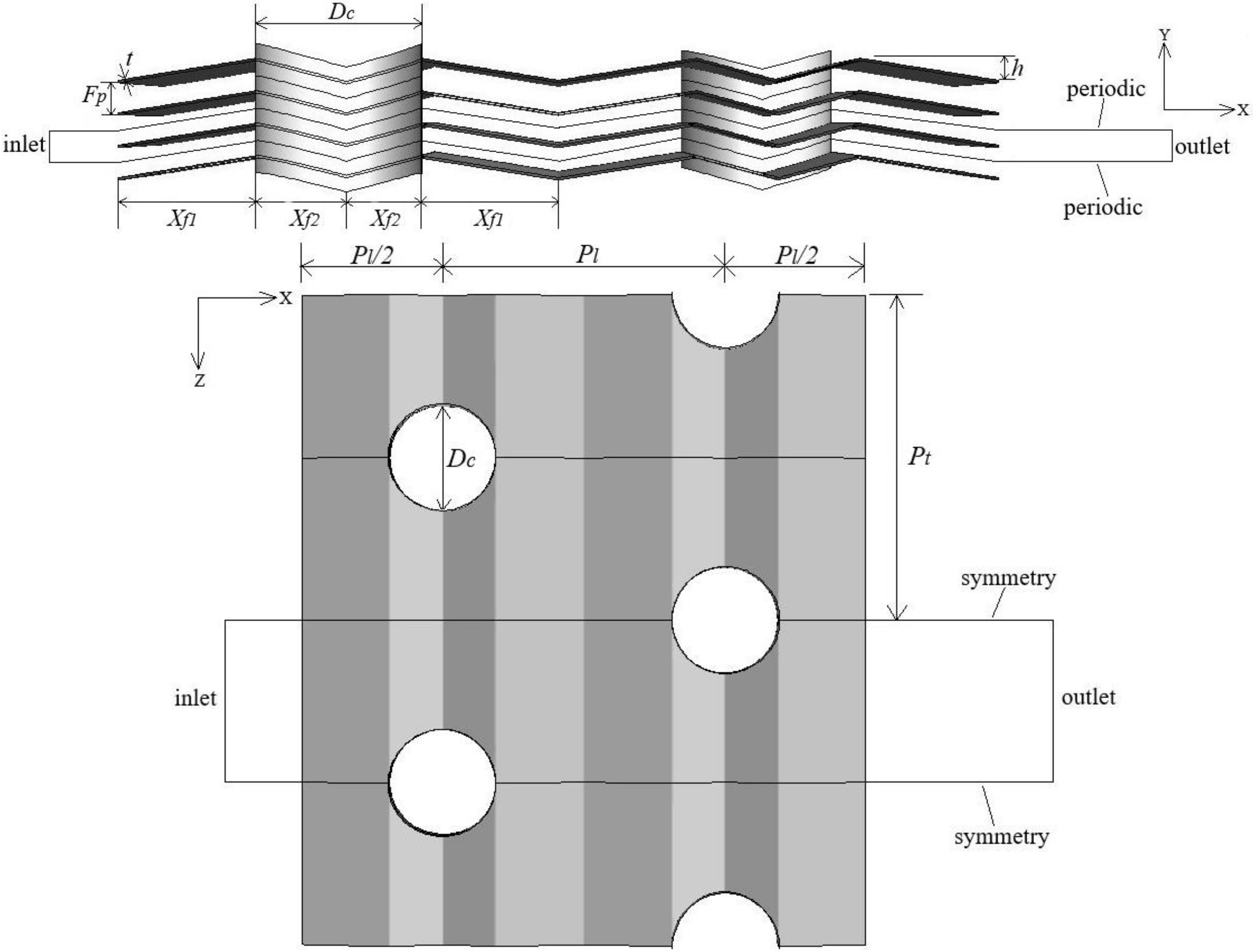
2.2. Boundary Conditions

Figure 2 depicts the computational domain and boundary conditions. The computational domain is extended 10 times the fin pitch at the fin inlet to have uniform velocity and 30 times the fin pitch at the fin outlet to avoid recirculation. Boundary conditions are specified as follows.
1. Upstream extended region
Air enters the computational domain with uniform velocity uin (0.5–4 m/s, with corresponding Reynolds number being 400–3000) and constant temperature Tin = 308 K. Turbulent intensity and turbulent viscosity ratio are specified at the air inlet. The velocity components in y and z directions are zero. Symmetric and periodic boundary conditions are applied to the side boundaries and top and bottom boundaries, respectively.
2. Downstream extended region
The pressure is set to atmospheric pressure at air outlet. Side boundaries are symmetric planes and the periodic boundary condition is assigned to top and bottom boundaries.
3. Fin region
Coupled (Tsolid = Tfluid) and non-slip condition are applied for solid surfaces. Constant tube temperature Ts = 318 K and non-slip condition are assigned to tube surfaces. Side boundaries are considered as symmetric planes on which normal gradients are zero and periodic boundary conditions are assumed for top and bottom planes.

2.3. Numerical Method

The discretization of governing equations is done by finite volume method and will be solved by Ansys Fluent software with boundary conditions. SIMPLE algorithm is applied for pressure and momentum coupling and second order upwind is used in order to improve accuracy. The convergence criteria are that residuals for continuity, velocities, kinetic energy and dissipation rate are less than 10−6 and residual for energy is less than 10−8. Unstructured fine grids are applied for fin region and structured coarse grids are used for upstream and downstream extended regions. The numerical analysis is carried out in the maximum air inlet velocity (4 m/s) by using three different meshes with fine, medium and large elements in order to ensure grid independence and to minimize computational cost. The obtained results by using these grids have been presented in Table 2. Based on this table, 1,373,000 cells can be selected for balance between accuracy and simulation running time. Also, for keeping Y+ less than 5, some adoptions for cells near wall surfaces are made.

2.4. Definition of Parameters

Pumping power (Pp) is calculated as follows.
P p = m ˙ ρ ( Δ P )  
where m is air mass flow rate, ρ is air density and ΔP is pressure drop.
Thermal resistance (Rth) and thermal conductance (ηoho) can also be obtained from the following formulas.
R t h = 1 η o h o A o = L M T D Q ˙  
η o h o = Q ˙ A o L M T D  
where Q is total heat transfer rate from the solid surfaces to the air. ηo is surface efficiency, ho is heat transfer coefficient of air and Ao is total surface area. LMTD is air log-mean temperature difference which can be determined from the following formula.
L M T D = ( T s T i n ) ( T s T o u t ) ln [ ( T s T i n ) / ( T s T o u t ) ]  
where Ts is tube surface temperature and Tin and Tout are mass-weighted averages of air inlet and outlet temperatures, respectively.

3. Results and Discussion

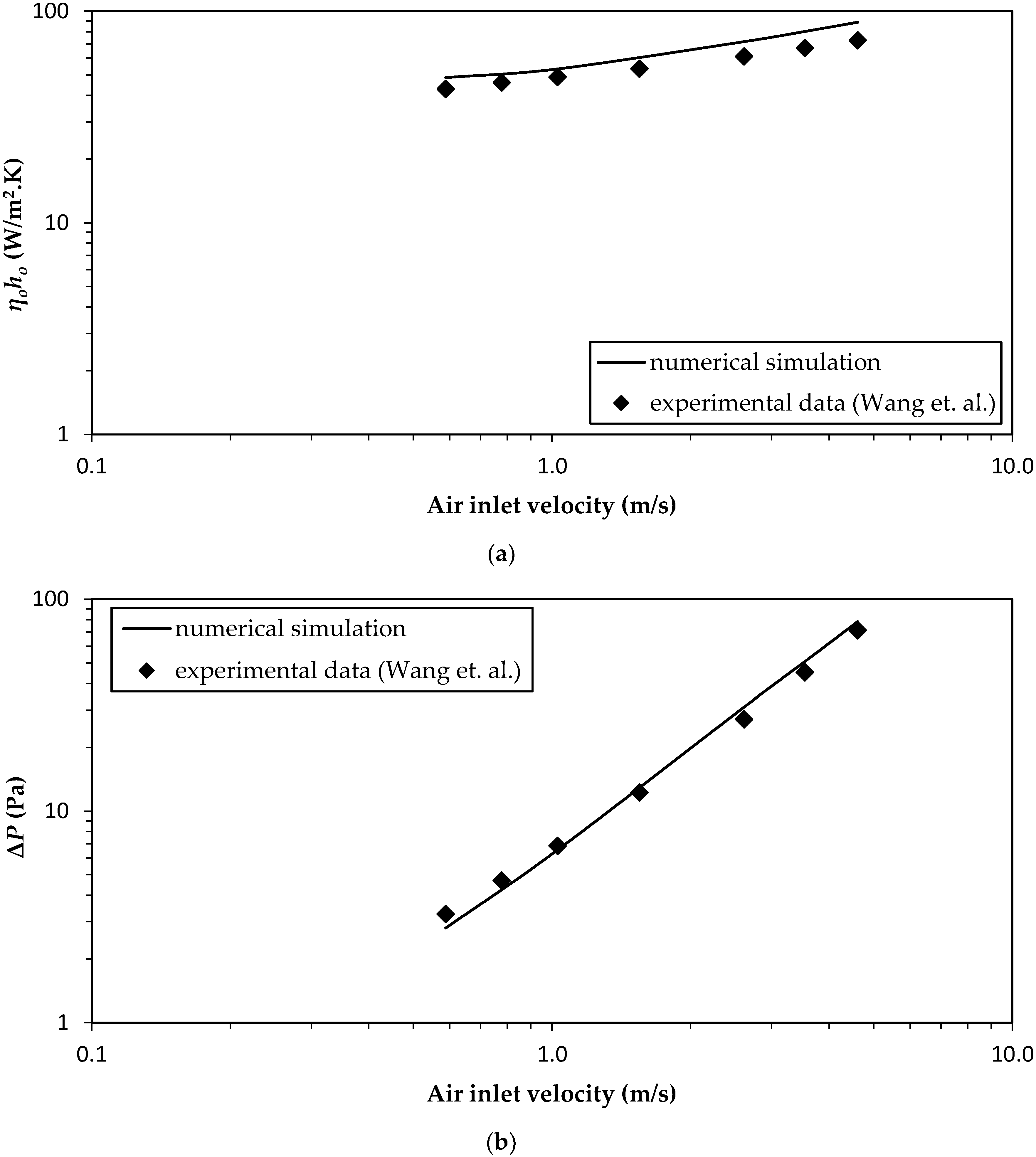
3.1. Validation of Numerical Simulations

In order to validate the reliability of numerical simulations, experimental results provided by Wang et al. [31] for a 1-row wavy fin-and-tube heat exchanger are used. Geometrical parameters for validation are specified in Table 1. Air inlet temperature is 291 K and air inlet velocity is varied from 0.5 m/s to 4.6 m/s. Figure 3a,b illustrate comparison of thermal conductance and pressure drop vs. air inlet velocity for numerical simulations and experimental results, respectively. Mean deviations for thermal conductance and pressure drop are 15% and 11%, respectively. Good agreement can be seen between numerical simulations and experimental data.

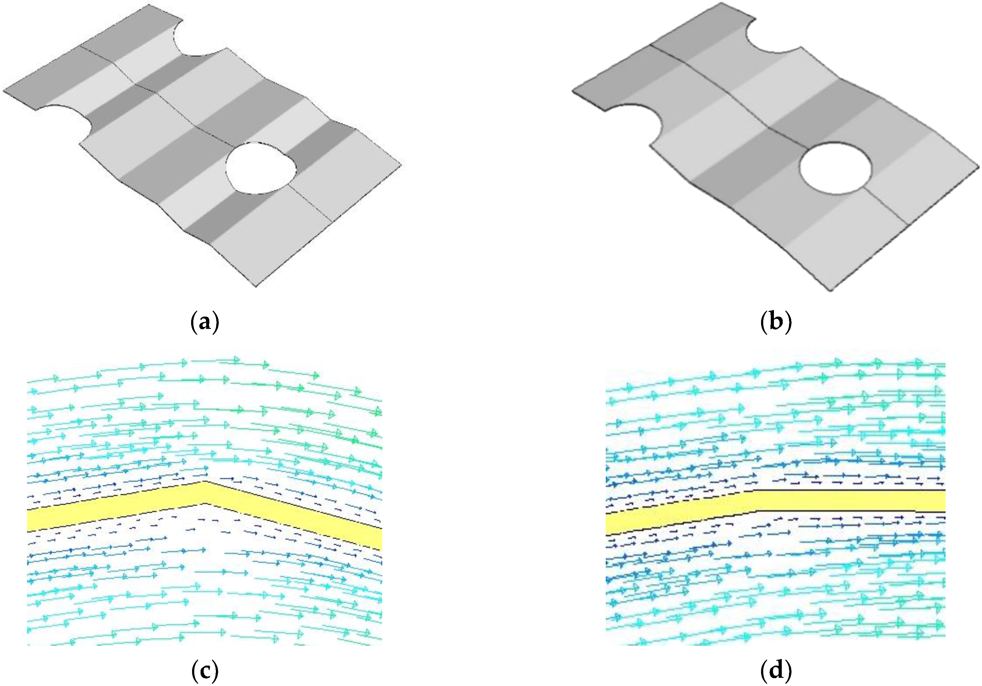
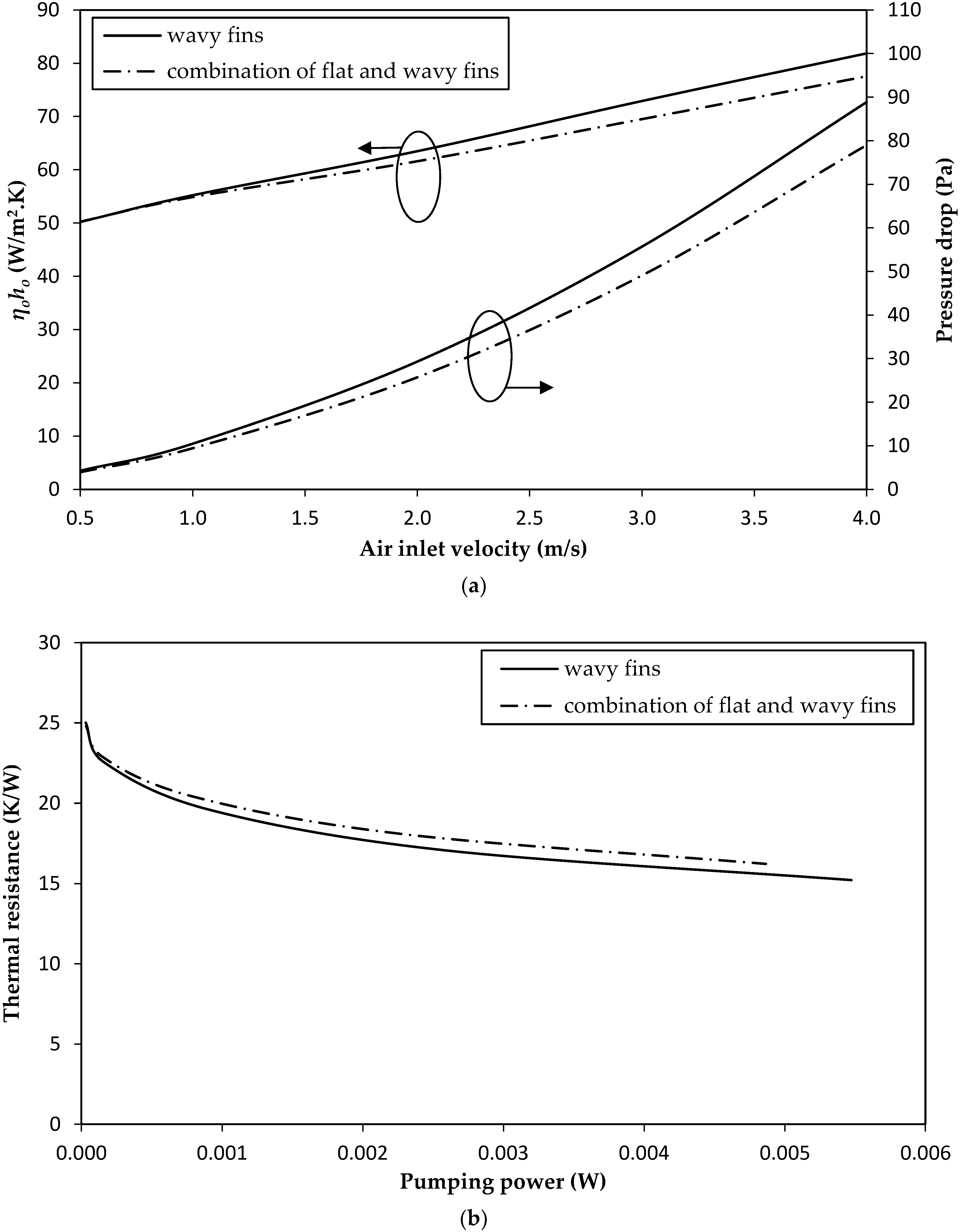
3.2. Combination of Flat and Wavy Fins

The wavy parts around the tubes (Xf2 in Figure 1 and Figure 4a) are replaced by flat fins as shown in Figure 4b. Other geometrical parameters are the same as Table 1 and air inlet velocity is changed from 0.5 m/s to 4 m/s. The objective of this alteration is to reduce the pressure drop caused by the corrugation. This can be made clear from the earlier work by Sparrow and Hossfeld [32], who showed that significant reduction in pressure drop is seen provided the portion of peak/valley of the wavy corrugation is smoothed. As expected, the thermal conductance and pressure drop for this combination design is lower than the original design as shown in Figure 5a. Further reduction in pressure drop in comparison with thermal conductance in the combination of flat and wavy fins is due to the reduction of the re-circulation zone with small flow velocity in this geometry relative to the reference wavy fins. Formation of the re-circulation zone in the crest part of wavy fins has been reported in different papers [9,33,34]. Yet the thermal resistance vs. pumping power for this combination against the reference wavy fin-and-tube heat exchanger is illustrated in Figure 5b. The thermal resistance for the combination of flat and wavy fins is increased by 3% and 5% for pumping powers 0.001 W and 0.005 W, respectively. This is because inferior mixing of airflow is observed by smoothing the peak/valley into a flat configuration and consequently the heat transfer rate from solid surfaces to the fluid will decrease accordingly. In fact, pumping power at the same air inlet velocity is decreased up to 11% for uin = 4 m/s while the reduction in thermal conductance is only 5% for this air inlet velocity as shown in Figure 5a. Re-circulation zones for the reference wavy fins and combination of flat and wavy fins are represented in Figure 4c,d, respectively. Also, the existence of flat fins around the circular tubes enhances the assembly of this new wavy fin geometry in comparison with the reference one.

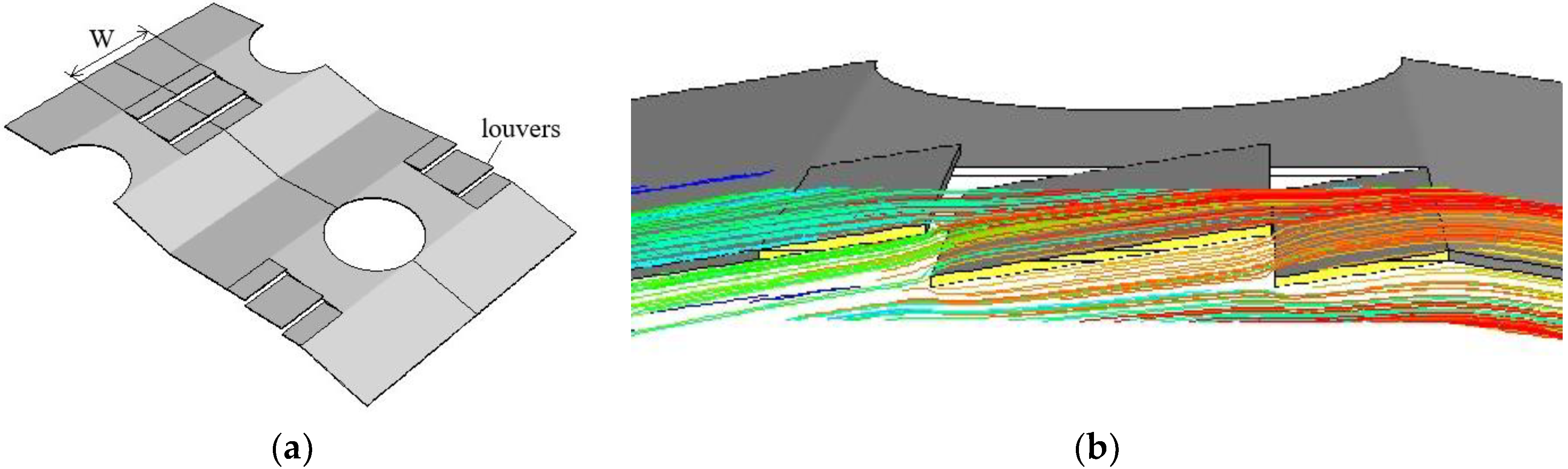
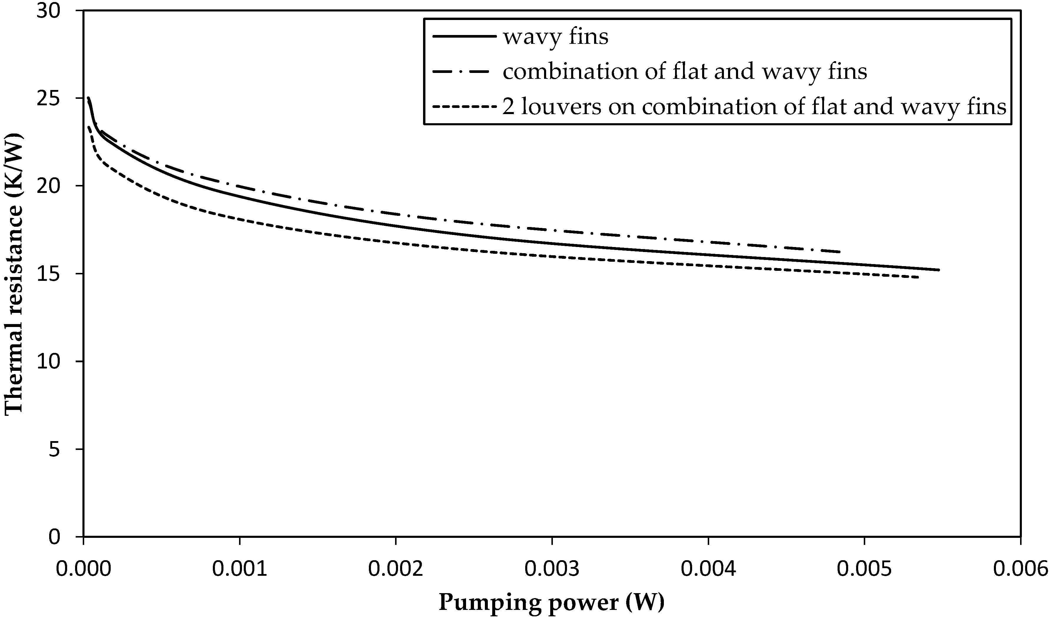
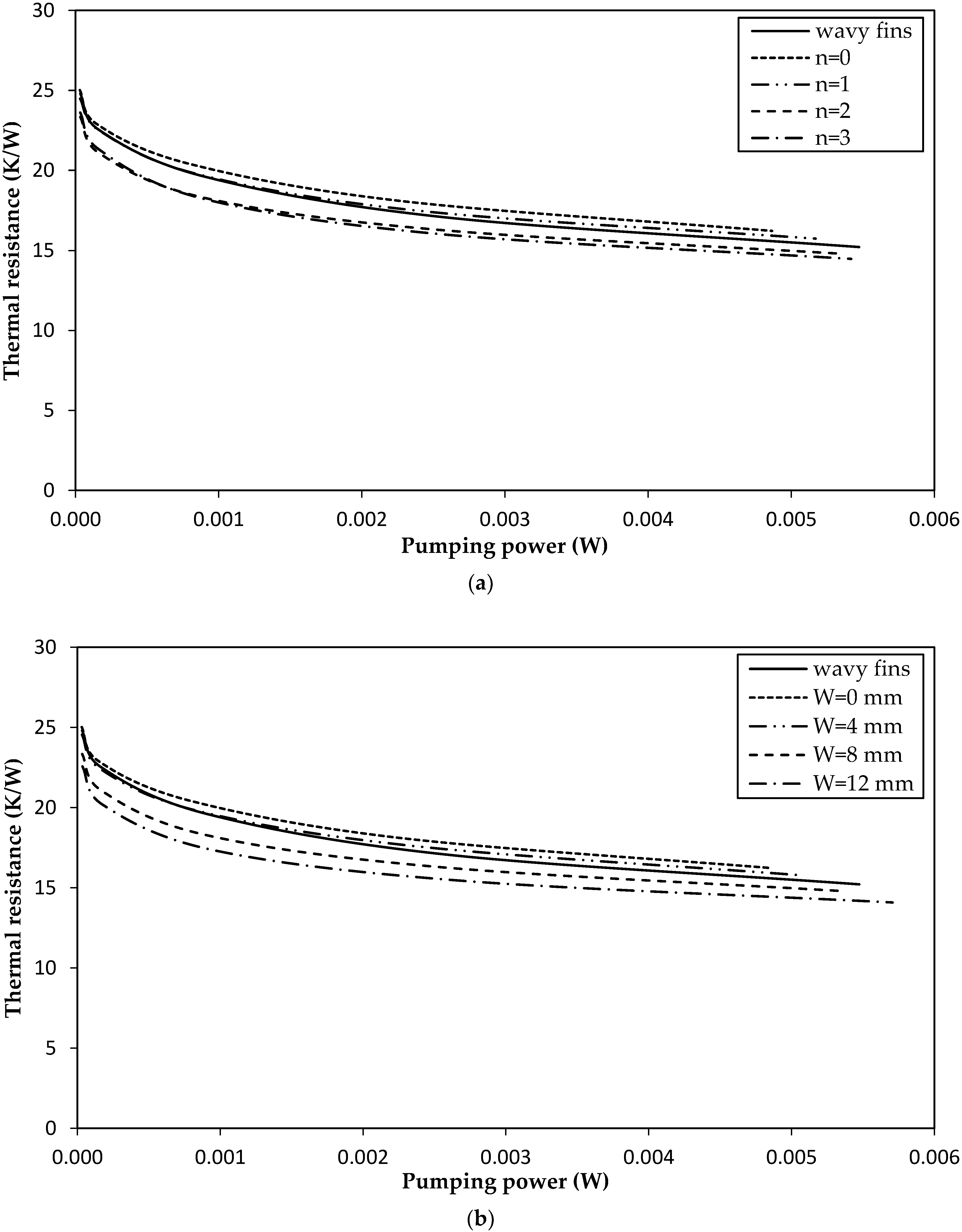
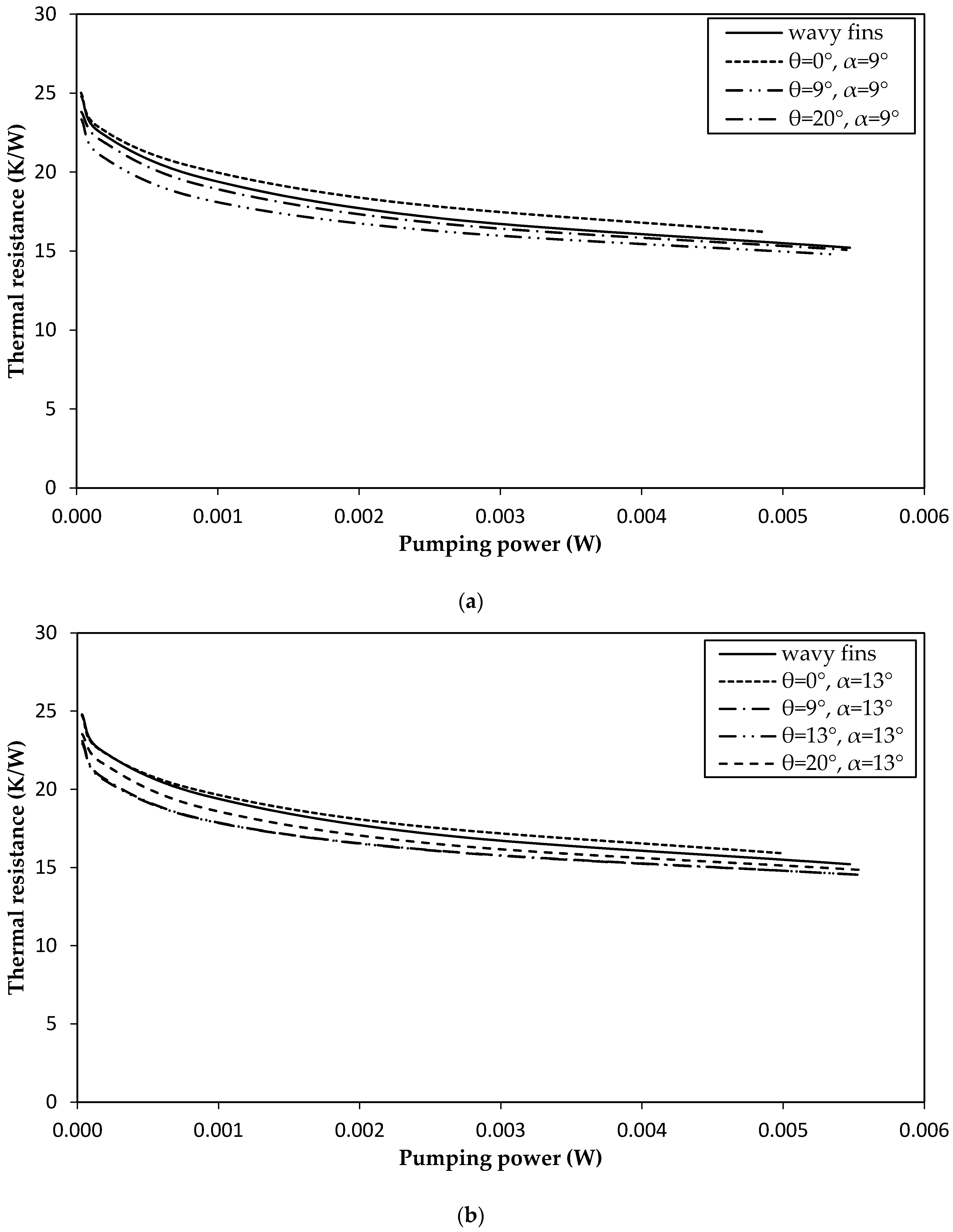
3.3. Combination of Louver, Flat and Wavy Fins

As mentioned earlier, changing wavy parts around the tubes into a plain surface in a wavy fin-and-tube heat exchanger is not effective. This is because the pressure drop reduction incurred by the flat portion also decreases the heat transfer appreciably. In order to remedy the performance loss of the flat portion, two louvers (n = 2) are added to the flat part to become a compound geometry as shown in Figure 6a. Louver width (W) is 8 mm and louver angle is selected to be the same as wavy angle (θ = α = 9°). Air inlet velocity is changed from 0.5 m/s to 4 m/s and the rest of the parameters are kept unchanged as specified in Table 1.
Figure 7 shows thermal resistance vs. pumping power for this new geometry in comparison with the reference wavy fins. It can be seen that the addition of louvers to the flat portion shows some 6% and 3% decrease in thermal resistance subject to pumping powers of 0.001 W and 0.005 W, respectively, relative to the reference wavy fins. By incorporating the louver design onto the flat portion, it is obvious that a fraction of fluid continues its direction along the wavy fins to pass through the louvers which causes much better mixing of airflow as seen in Figure 6b, in which the fluid streamlines through the louvers while each line with a different color represents each particle’s path. The presence of louvers also restarts the boundary layer, thereby increasing the heat transfer performance. These two phenomena (better mixing and boundary layer restarting) lead to lower thermal resistances.
Effects of number of louvers (n), width of louvers (W) and louver angle (θ) on the heat transfer characteristics are also investigated. Firstly, the number of louvers (n) ranges from 0 (flat) to 3 while the louver width (W) and louver angle (θ) remain unchanged as 8 mm and 9° (same as wavy angle), respectively. All other geometrical parameters are the same as Table 1 and the air inlet velocity is changed from 0.5 m/s to 4 m/s. Thermal resistance vs. pumping power for different number of louvers are depicted in Figure 8a. As discussed before, the case without louver (n = 0) shows a much higher thermal resistance in comparison with the reference wavy fins. However, by raising the number of louvers, better mixing amid the adjacent channel, as well as boundary layer reseating, the thermal resistance subject to the same pumping power is decreased. In fact, adding two or three louvers will result in 6% and 3% or 7% and 5% reductions in thermal resistances with pumping powers of 0.001 W and 0.005 W, respectively, in comparison with the reference wavy fins. Notice that the addition of one louver (n = 1) can decrease thermal resistance as compared to the case without louver (n = 0), but the heat transfer improvement due to higher mixing is not so pronounced which may even be inferior to the reference wavy fins.
A further increase of louver, n = 2 and θ = 9° (same as wavy angle), are selected and width of louvers (W) are changed from 0 mm (no louver) to 12 mm. Thermal resistance vs. pumping power in Figure 8b shows a detectable lower thermal resistance than the reference case. As shown in Figure 6b, more fraction of fluid can go through louvers by increasing the louver width which causes better mixing, thereby resulting in lower thermal resistance. Reductions of thermal resistances are 11% and 7% for pumping powers 0.001 W and 0.005 W, respectively, for W = 12 mm in comparison with the reference wavy fins. It can also be seen that the case of W = 4 mm has a lower thermal resistance relative to W = 0 mm (no louver), but the increase in heat transfer rate due to higher mixing is not so significant to reduce the thermal resistance further than the reference wavy fins.
The influence of louver angle (θ) is also investigated and two different cases are studied:
  • θ = 0°, 9° and 20° with wavy angle (α) of 9°
  • θ = 0°, 9°, 13° and 20° with wavy angle (α) of 13°
It should be noted that waffle height (h) shall be increased to 1.4 mm (same as fin pitch) for case 2 in order to increase wavy angle to 13°. W and n remain unchanged as 8 mm and 2, respectively, and all other geometrical parameters are the same as Table 1. Air inlet velocity is changed from 0.5 m/s to 4 m/s. Thermal resistance vs. pumping power for case 1 and case 2 are illustrated in Figure 9a,b, respectively. As mentioned earlier, a combination of flat and wavy fins without louver (θ = 0°) has the maximum thermal resistance for both cases which is even higher than the reference wavy fins. It can be seen that minimum thermal resistances in the same pumping powers can be obtained for geometries with louver angles (θ) being equal to the wavy angles (α). Reduction values of thermal resistances for the case having the same louver and wavy angles are 3–6% and 5–8% for wavy angles of 9° and 13°, respectively. In essence, the optimum louver angle is equal to wavy angle. It is obvious that pressure drops for the continuation of fluid flow from wavy fins through louvers are lower because of no change in flow direction when the louver angle is the same as the wavy angle. Hence, more fraction of fluid tends to go through louvers, which causes higher mixing and, as a result, lowers thermal resistance in comparison with other louver angles.

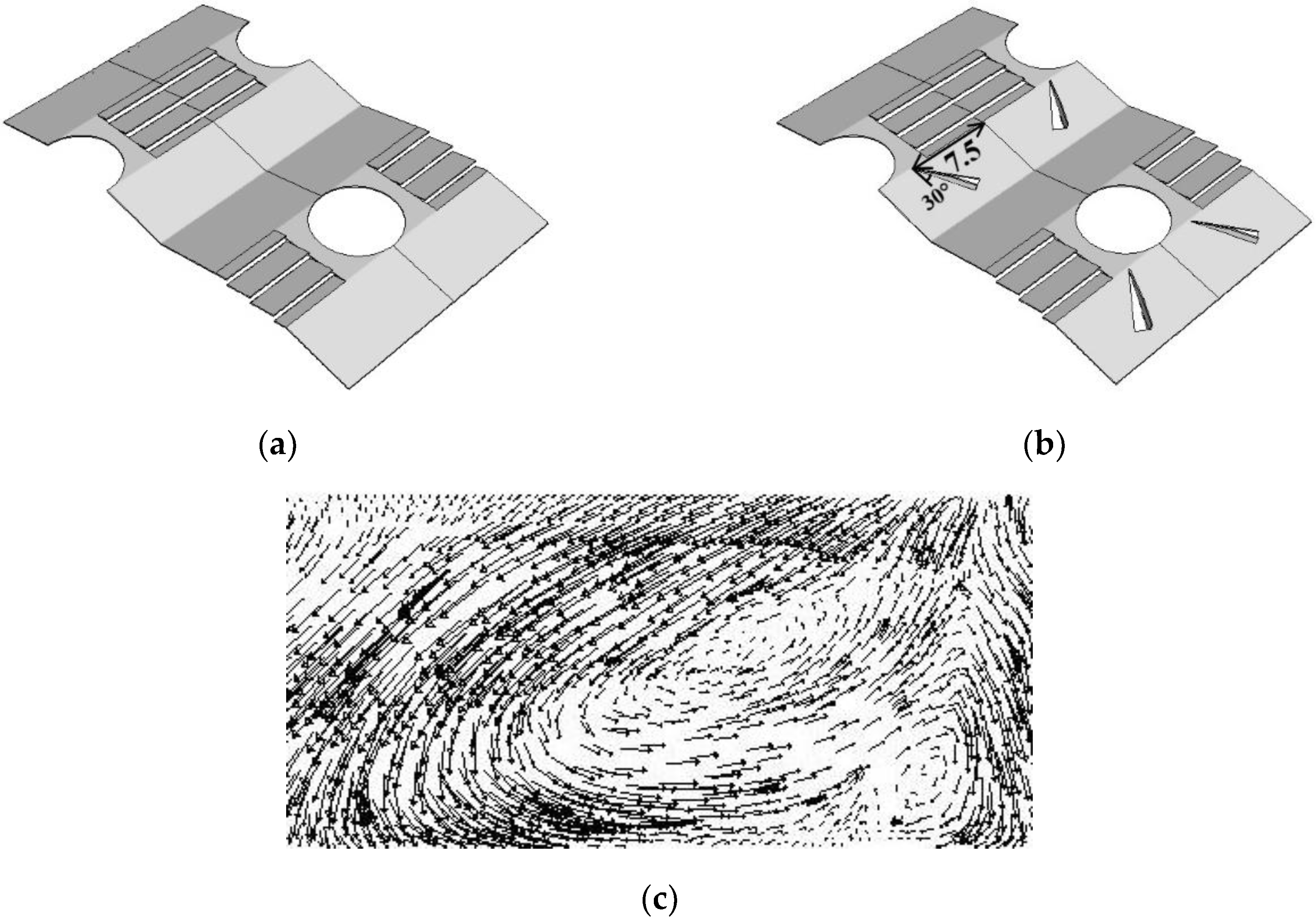
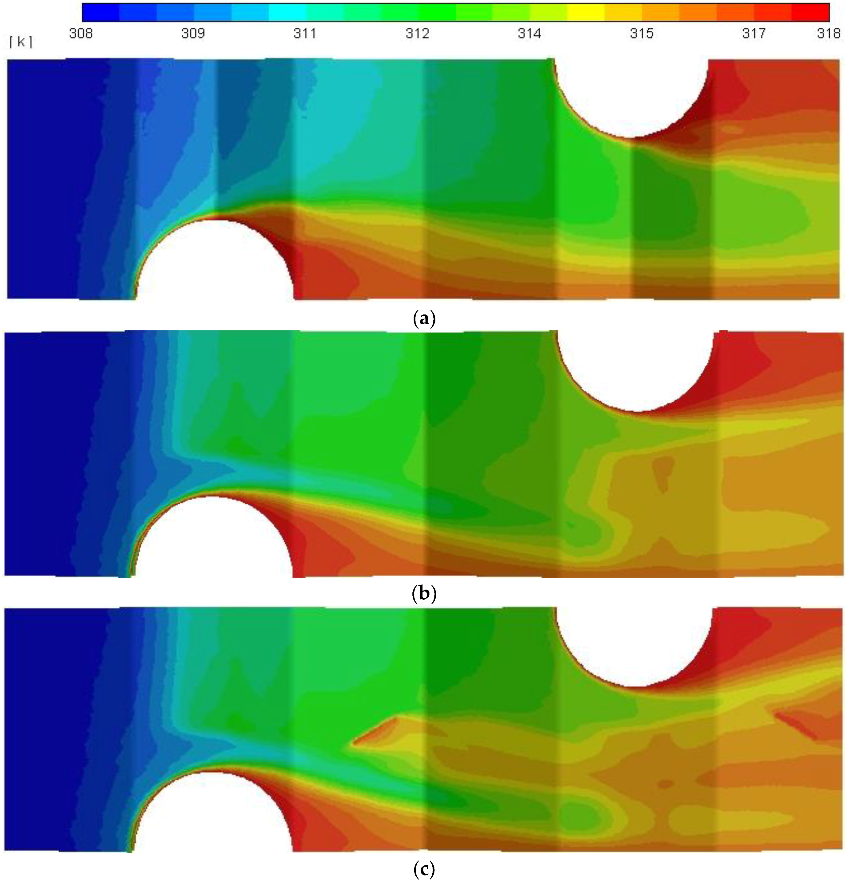
3.4. Compound Geometries

As aforementioned, increases in louver number and width of louver, with louver angle being equal to wavy angle, give the most reduction in thermal resistance in comparison with the reference wavy fins. Also, thermal resistance for wavy angle of 13° (waffle height same as fin pitch) is lower than thermal resistance for wavy angle of 9° (the reference wavy fins) under the same conditions and that with louver angle equal to wavy angle. Therefore, it is expected that the combination of louver, flat and wavy fins with n = 3, W = 12 mm and θ = α = 13° (h = 1.4 mm) may yield the most reduction in thermal resistance. This compound geometry is simulated as shown in Figure 10a. All other parameters remained unchanged based on Table 1 and air inlet velocity is changed from 0.5 m/s to 4 m/s. It is found that some 16% and 12% reductions in thermal resistances can be gained by this compound geometry for pumping powers of 0.001 W and 0.005 W, respectively, as illustrated in Figure 11.
Recently, longitudinal vortex generators (LVG) have been widely used in compact fin heat exchangers in order to enhance heat transfer characteristics. Longitudinal vortex generators have different shapes and delta winglets are the most commonly adopted LVGs. Punching out vortex generators on wavy fins has also been studied and investigated in different literatures [17,19,23]. In this regard, punching out pairs of delta winglets on the compound geometry, as shown in Figure 10b, can further enhance heat transfer characteristics. The corresponding angle of attack of vortex generators is 30°. Chord (l) and height of delta (H) winglets are 5 mm and 1.1 mm, respectively. The corresponding angle of attack is 30° and locations of delta winglets are specified in Figure 10b. Thermal resistance vs. pumping curve (Figure 11) indicates that thermal resistance will decrease 18% and 15% for pumping powers of 0.001 W and 0.005 W, respectively.
For further examination of the influence of this compound enhancement, one can see the flow separation on the leading edge of delta winglets forms longitudinal vortices, which produces swirled flow. This swirled flow increases mixing of airflow. Therefore, heat transfer is increased and the thermal resistance is reduced further. Vortices generated by delta winglets on wavy fins in a vertical plane (18 mm distance from fin inlet) behind the delta winglets are shown in Figure 10c. These vortices will be vanished downstream by viscous dissipation. Further information regarding heat transfer enhancement by longitudinal vortices can be found in Reference [35].
Comparison of temperature contours for the reference wavy fins and compound geometry with and without vortex generators for air inlet velocity of 2 m/s in the middle of fin pitch can be seen in Figure 12. It is obvious that air temperature for this compound geometry (Figure 12b) is much higher than the reference wavy fins without any improvement (Figure 12a), which indicates a higher heat transfer rate from solid surfaces to the fluid and consequently lower thermal resistance in the modified wavy fins. Further increase in air temperatures in compound geometry with vortex generators (Figure 12c) indicates a much higher enhancement in this new geometry, resulting from generated vortices by delta winglets.

4. Conclusions

The present study adopts a 3D turbulent flow numerical simulation to improve heat transfer characteristics of wavy fin-and-tube heat exchangers. Combination of louver, flat, wavy and vortex generator yields some considerable reduction of thermal resistances subject to the same pumping powers. Effects of louver parameters such as number of louver, width and angle are investigated in detail. In addition, adding punching vortex generators on this compound geometry is also studied. Based on the foregoing discussions, some conclusions are drawn as follows.
Substitution of wavy fins around the tubes with flat fins will decrease heat transfer characteristics and pressure drop of wavy fins. However, it is not effective in terms of thermal resistance subject to the same pumping power.
  • Increasing the louver number in flat portion leads to a drop of thermal resistance; by adding two louvers with a width of 8 mm and the louver angle being the same as wavy angle (9°) can compensate performance loss, so that thermal resistance can be reduced by 6% and 3% in comparison with the reference wavy fins for pumping powers of 0.001 W and 0.005 W, respectively.
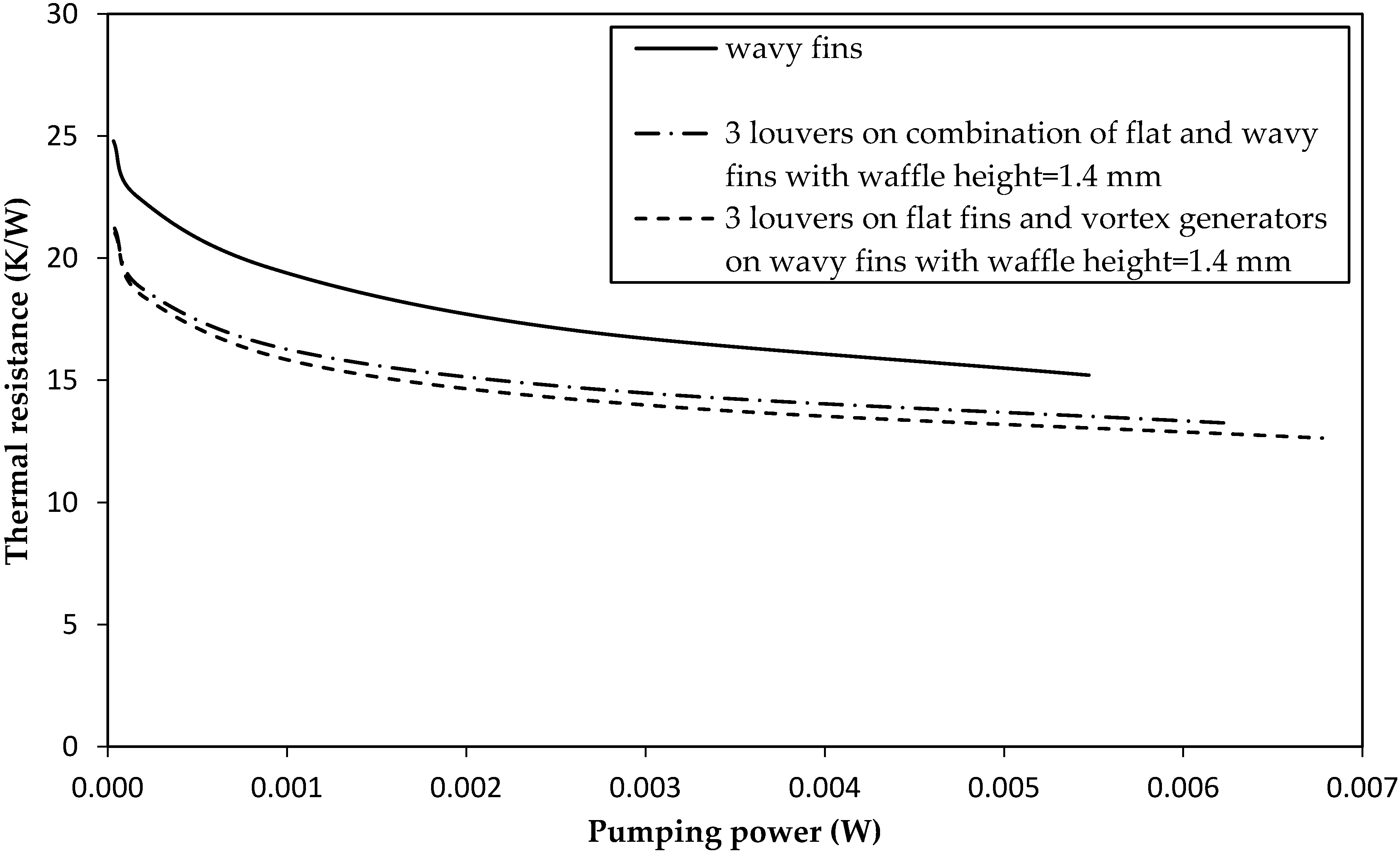
  • It is found that with increases of louver number (n) and width (W), the thermal resistances decrease and yield an optimum value for louver angle (θ) that is equal to wavy angle (α). Also, the compound geometry with n = 3, W = 12 mm and θ = α = 13° (waffle height same as fin pitch) have the lowest thermal resistances, which are 16% and 12% reductions in pumping powers 0.001 W and 0.005 W, respectively.
  • Using punching out pairs of delta winglets onto this compound geometry can further enhance heat transfer characteristics, yielding 18% and 15% reductions in thermal resistances subject to pumping powers of 0.001 W and 0.005 W, respectively.

Author Contributions

All the authors have contributed their efforts to complete the paper. A.S. conducted the simulation parts, analyzed the simulation results and prepared original draft. S.K. and H.N. helped in performing simulations and analyzing results. Funding acquisition was performed by J.-S.L.; C.-C.W. supervised the work and review and editing of manuscript were also done by him.

Acknowledgments

The authors would like to thank for the support from the Ministry of Science and Technology of Taiwan, under contract 107-2622-E-009-002-CC2 and 104-2221-E-009-184-MY3. The fourth author appreciates some financial support from the Bureau of Energy, Ministry of Economic Affairs of Taiwan.

Conflicts of Interest

The authors declare no conflict of interest.

Nomenclature

Aototal surface area (m2)
cpspecific heat capacity (J/kg·K)
Dctube collar outside diameter (m)
Fpfin pitch (m)
Gkgeneration of turbulence kinetic energy due to the mean velocity gradients (J/kg)
Hheight of delta winglets (m)
hwaffle height (m)
hoheat transfer coefficient of air (W/m2·K)
kturbulent kinetic energy (J/kg)
kffluid thermal conductivity (W/m·K)
lchord of delta winglets (m)
LMTDair log-mean temperature difference (K)
mair mass flow rate (kg/s)
Nnumber of tube rows
nnumber of louvers
Ppressure (Pa)
Pllongitudinal tube pitch (m)
Pppumping power (W)
Pttransversal tube pitch (m)
Qtotal heat transfer rate to the fluid (W)
Rththermal resistance (K/W)
Ttemperature (K)
tfin thickness (m)
uvelocity (m/s)
Wlouver width (m)
Xf1projected wavy length (1st part) (m)
Xf2projected wavy length (2nd part) (m)
Y+Y plus
Greek symbols
αwavy angle (°)
αkinverse effective Prandtl numbers for k
αεinverse effective Prandtl numbers for ε
αVGattack angle of vortex generators (°)
ΔPpressure drop (Pa)
εdissipation rate (m2/s3)
ηosurface efficiency
μdynamic viscosity (kg/m·s)
μtturbulent dynamic viscosity (kg/m·s)
ρdensity (kg/m3)
θlouver angle (°)
Subscripts
i, j, ktensor index
ininlet
outoutlet
stube wall

References

  1. Shah, R.K.; Sekulic, D.P. Fundamentals of Heat Exchanger Design; John Wiley Sons: Hoboken, NJ, USA, 2007; Available online: https://onlinelibrary.wiley.com/doi/book/10.1002/9780470172605 (accessed on 24 July 2018).
  2. Guo, Y.; Cheng, T.; Du, X.; Yang, L. Anti-Freezing mechanism analysis of a finned flat tube in an air-cooled condenser. Energies 2017, 10, 1872. [Google Scholar]
  3. Lee, M.-Y.; Kim, Y.; Lee, D.-Y. Experimental study on frost height of round plate fin-tube heat exchangers for mobile heat pumps. Energies 2012, 5, 3479–3491. [Google Scholar] [CrossRef]
  4. Saleem, A.; Kim, M.-H. CFD analysis on the air-side thermal-hydraulic performance of multi-louvered fin heat exchangers at low Reynolds numbers. Energies 2017, 10, 823. [Google Scholar] [CrossRef]
  5. Chen, H.; Wang, Y.; Zhao, Q.; Ma, H.; Li, Y.; Chen, Z. Experimental investigation of heat transfer and pressure drop characteristics of H-type finned tube banks. Energies 2014, 7, 7094–7104. [Google Scholar] [CrossRef]
  6. Sparrow, E.M.; Comb, J.W. Effect of interwall spacing and fluid flow inlet conditions on a corrugated-wall heat exchanger. Int. J. Heat Mass Transf. 1983, 26, 993–1005. [Google Scholar] [CrossRef]
  7. Wang, C.C.; Fu, W.L.; Chang, C.T. Heat transfer and friction characteristics of typical wavy fin-and-tube heat exchangers. Exp. Therm. Fluid Sci. 1997, 14, 174–186. [Google Scholar] [CrossRef]
  8. Wang, C.C. Investigation of Wavy Fin-and-Tube Heat Exchangers: A Contribution to Databank. Exp. Heat Transf. 1999, 12, 73–89. [Google Scholar] [CrossRef]
  9. Wang, C.C.; Chang, J.Y.; Chiou, N.F. Effects of Waffle Height on the Air-Side Performance of Wavy Fin-and-Tube Heat Exchangers. Heat Transf. Eng. 1999, 20, 45–56. [Google Scholar]
  10. Wongwises, S.; Chokeman, Y. Effect of fin pitch and number of tube rows on the air side performance of herringbone wavy fin and tube heat exchangers. Energy Convers. Manag. 2005, 46, 2216–2231. [Google Scholar] [CrossRef]
  11. Chokeman, Y.; Wongwises, S. Effect of fin pattern on the air-side performance of herringbone wavy fin-and-tube heat exchangers. Heat Mass Transf. 2005, 41, 642–650. [Google Scholar] [CrossRef]
  12. Dong, J.; Chen, J.; Chen, Z.; Zhou, Y.; Zhang, W. Heat transfer and pressure drop correlations for the wavy fin and flat tube heat exchangers. Appl. Therm. Eng. 2007, 27, 2066–2073. [Google Scholar]
  13. Moorthy, P.; Oumer, A.; Ishak, M. Experimental investigation on effect of fin shape on the thermal-hydraulic performance of compact fin-and-tube heat exchangers. In Proceedings of the Malaysian Technical Universities Conference on Engineering and Technology, Penang, Malaysia, 6–7 December 2017. [Google Scholar]
  14. Tao, Y.B.; He, Y.L.; Huang, J.; Wu, Z.G.; Tao, W.Q. Three-dimensional numerical study of wavy fin-and-tube heat exchangers and field synergy principle analysis. Int. J. Heat Mass Transf. 2007, 50, 1163–1175. [Google Scholar] [CrossRef]
  15. Cheng, Y.; Lee, T.; Low, H. Numerical analysis of periodically developed fluid flow and heat transfer characteristics in the triangular wavy fin-and-tube heat exchanger based on field synergy principle. Numer. Heat Transf. 2007, 53, 821–842. [Google Scholar] [CrossRef]
  16. Tian, L.; He, Y.; Tao, Y.; Tao, W. A comparative study on the air-side performance of wavy fin-and-tube heat exchanger with punched delta winglets in staggered and in-line arrangements. Int. J. Therm. Sci. 2009, 48, 1765–1776. [Google Scholar] [CrossRef]
  17. Gong, J.; Min, C.; Qi, C.; Wang, E.; Tian, L. Numerical simulation of flow and heat transfer characteristics in wavy fin-and-tube heat exchanger with combined longitudinal vortex generators. Int. Commun. Heat Mass Transf. 2013, 43, 53–56. [Google Scholar] [CrossRef]
  18. Bhuiyan, A.A.; Amin, M.R.; Naser, J.; Islam, A. Effects of geometric parameters for wavy finned-tube heat exchanger in turbulent flow: A CFD modeling. Front. Heat Mass Transf. 2015, 6. [Google Scholar] [CrossRef]
  19. Lotfi, B.; Sundén, B.; Wang, Q. An investigation of the thermo-hydraulic performance of the smooth wavy fin-and-elliptical tube heat exchangers utilizing new type vortex generators. Appl. Energy 2016, 162, 1282–1302. [Google Scholar] [CrossRef]
  20. Gholami, A.; Wahid, M.A.; Mohammed, H. Thermal-hydraulic performance of fin-and-oval tube compact heat exchangers with innovative design of corrugated fin patterns. Int. J. Heat Mass Transf. 2017, 106, 573–592. [Google Scholar] [CrossRef]
  21. Darvish Damavandi, M.; Forouzanmehr, M.; Safikhani, H. Modeling and Pareto based multi-objective optimization of wavy fin-and-elliptical tube heat exchangers using CFD and NSGA-II algorithm. Appl. Therm. Eng. 2017, 111, 325–339. [Google Scholar] [CrossRef]
  22. Xue, Y.; Ge, Z.; Du, X.; Yang, L. On the heat transfer enhancement of plate fin heat exchanger. Energies 2018, 11, 1398. [Google Scholar] [CrossRef]
  23. Du, X.; Feng, L.; Yang, Y.; Yang, L. Experimental study on heat transfer enhancement of wavy finned flat tube with longitudinal vortex generators. Appl. Therm. Eng. 2013, 50, 55–62. [Google Scholar] [CrossRef]
  24. Ma, Q.; Wu, X.; Chu, F.; Zhu, B. Numerical simulation of frosting on wavy fin-and-tube heat exchanger surfaces. In Proceedings of the Problems of Thermal Physics and Power Engineering, Moscow, Russia, 9–11 October 2017. [Google Scholar]
  25. Zhang, X.; Wang, Y.; Li, M.; Wang, S.; Li, X. Improved flow and heat transfer characteristics for heat exchanger by using a new humped wavy fin. Appl. Therm. Eng. 2017, 124, 510–520. [Google Scholar] [CrossRef]
  26. Li, M.J.; Zhang, H.; Zhang, J.; Mu, Y.T.; Tian, E.; Dan, D.; Zhang, X.D.; Tao, W.Q. Experimental and numerical study and comparison of performance for wavy fin and a plain fin with radiantly arranged winglets around each tube in fin-and-tube heat exchangers. Appl. Therm. Eng. 2018, 133, 298–307. [Google Scholar] [CrossRef]
  27. Sadeghianjahromi, A.; Kheradmand, S.; Nemati, H. Developed correlations for heat transfer and flow friction characteristics of louvered finned tube heat exchangers. Int. J. Therm. Sci. 2018, 129, 135–144. [Google Scholar] [CrossRef]
  28. Nemati, H.; Moghimi, M. Numerical study of flow over annular-finned tube heat exchangers by different turbulent Models. CFD Lett. 2014, 6, 101–112. [Google Scholar]
  29. CFD Based Heat transfer Analysis of Various Wavy Fin-and-Tube Heat Exchanger. Available online: http://inpressco.com/wp-content/uploads/2016/07/Paper49258-261.pdf (accessed on 24 July 2018).
  30. Orszag, S.A.; Yakhot, V.; Flannery, W.S.; Boysan, F.; Choudhury, D.; Maruzewski, J.; Patel, B. Renormalization group modeling and turbulence simulations. Presented at the International Conference on Near-Wall Turbulent Flows, Tempe, AZ, USA, 15–17 March 1993. [Google Scholar]
  31. Wang, C.C.; Jang, J.Y.; Chiou, N.F. A heat transfer and friction correlation for wavy fin-and-tube heat exchangers. Int. J. Heat Mass Transf. 1999, 42, 1919–1924. [Google Scholar] [CrossRef]
  32. Sparrow, E.; Hossfeld, L. Effect of rounding of protruding edges on heat transfer and pressure drop in a duct. Int. J. Heat Mass Transf. 1984, 27, 1715–1723. [Google Scholar] [CrossRef]
  33. Molki, M.; Yuen, C. Effect of interwall spacing on heat transfer and pressure drop in a corrugated-wall duct. Int. J. Heat Mass Transf. 1986, 29, 987–997. [Google Scholar] [CrossRef]
  34. Youn, B.; Kim, N. An experimental investigation on the airside performance of fin-and-tube heat exchangers having sinusoidal wave fins. Heat Mass Transf. 2007, 43, 1249–1262. [Google Scholar] [CrossRef]
  35. Romero-Méndez, R.; Sen, M.; Yang, K.T.; McClain, R.L. Enhancement of heat transfer in an inviscid-flow thermal boundary layer due to a Rankine vortex. Int. J. Heat Mass Transf. 1998, 41, 3829–3840. [Google Scholar] [CrossRef]
Figure 1. Physical model and geometrical parameters of simulated wavy fin.
Energies 11 01959 g001
Figure 2. Computational domain of simulated wavy fin.
Energies 11 01959 g002
Figure 3. Comparison of numerical and experimental results done by Wang et al. [31]: (a) Thermal conductance; (b) Pressure drop.
Energies 11 01959 g003
Figure 4. Comparison of the referenced wavy fins and combination of flat and wavy fins: (a) Reference wavy fin geometry; (b) combination of flat and wavy fins geometry; (c) re-circulation zone in wavy fins; (d) re-circulation zone in combination of flat and wavy fins.
Energies 11 01959 g004
Figure 5. Heat transfer and pressure drop characteristics for comparison between wavy fins and combination of flat and wavy fins: (a) thermal conductance and pressure drop vs. air inlet velocity; (b) thermal resistance vs. pumping power.
Energies 11 01959 g005
Figure 6. Combination of louver, flat and wavy fins: (a) geometry; (b) fluid streamlines through louvers.
Energies 11 01959 g006
Figure 7. Thermal resistance vs. pumping power for comparison between wavy fins and combination of flat and wavy fins with and without louvers (W = 8 mm, n = 2).
Energies 11 01959 g007
Figure 8. Thermal resistance vs. pumping power in combination of louver, flat and wavy fins: (a) Different number of louvers (W = 8 mm, θ = 9°); (b) different widths of louvers (n = 2, θ = 9°).
Energies 11 01959 g008
Figure 9. Thermal resistance vs. pumping power in combination of louver, flat and wavy fins: (a) W = 8 mm, n = 2, and α = 9°; (b) W = 8 mm, n = 2, and α = 13°.
Energies 11 01959 g009
Figure 10. Compound geometries (n = 3, W = 12 mm and θ = α = 13°): (a) Without vortex generators; (b) with vortex generators; (c) vortices generated by delta winglets.
Energies 11 01959 g010
Figure 11. Thermal resistance vs. pumping power for comparison between wavy fins and compound geometry (n = 3, W = 12 mm and θ = α = 13°) with and without vortex generators.
Energies 11 01959 g011
Figure 12. Air temperature contours in the middle of fin pitch (uin = 2 m/s): (a) Reference wavy fins; (b) compound geometry without vortex generators; (c) compound geometry with vortex generators.
Energies 11 01959 g012
Table 1. Geometrical parameters of simulated wavy fins.
ParametersValues for ValidationValues for Reference Wavy Fins
Tube collar outside diameter (Dc) (mm)10.387.2
Number of tube rows (N)12
Fin thickness (t) (mm)0.120.105
Fin pitch (Fp) (mm)1.621.4
Longitudinal tube pitch (Pl) (mm)19.0519.05
Transversal tube pitch (Pt) (mm)25.422
Waffle height (h) (mm)1.180.95
Projected wavy length (1st part) (Xf1) (mm)4.76255.975
Projected wavy length (2nd part) (Xf2) (mm)4.76253.55
Table 2. Grid study results.
Number of CellsRth (K/W)Pp (W)
590,00014.160.005607
1,373,00015.190.005473
2,920,00015.340.005436

