Research on Distributed Power Capacity and Site Optimization Planning of AC/DC Hybrid Micrograms Considering Line Factors

1
Anhui Provincial Laboratory of New Energy Utilization and Energy Conservation, Hefei University of Technology, Hefei 230009, China
2
State Grid Zhejiang Electric Power Company, Hangzhou 310007, China
*
Author to whom correspondence should be addressed.
Energies 2018, 11(8), 1930; https://doi.org/10.3390/en11081930
Submission received: 26 June 2018
/
Revised: 17 July 2018
/
Accepted: 19 July 2018
/
Published: 24 July 2018
(This article belongs to the Section F: Electrical Engineering)
Abstract
:With the rapid development of AC/DC hybrid microgrids and the widespread use of distributed power resources, planning strategies for microgrids with high-density distributed power generation have become an urgent problem. Because current research on microgrid planning has not considered line factors, this paper analyses the planning of an AC/DC hybrid microgrid based on an AC microgrid. The capacity and siting of the distributed power resources are optimized, taking into account the influence of the line investment cost and the interactive power upper limit on the planning results. In the proposed model, the objective is aimed at minimizing the sum of investment cost, load-loss economic cost, and system losses, taking into consideration power balance constraints and feeder number constraints. The commercial solver CPLEX is applied to attain the optimal distributed power capacity and site. The theoretical results are verified by an actual system.
1. Introduction
Distributed renewable energy has been widely used in recent years because it improves environmental protection, and has renewable characteristics. To increase the utilization rate of renewable energy sources and reduce the energy loss of renewable energy sources integrated into traditional power systems, AC/DC hybrid microgrids have been developed rapidly. By accommodating distributed energy and meeting AC and DC load demands because of its two components—an AC microgrid and a DC microgrid—the AC/DC hybrid microgrid has unique advantages. Thus, hybrid microgrids have become a popular research topic in recent years [1,2,3,4,5,6].
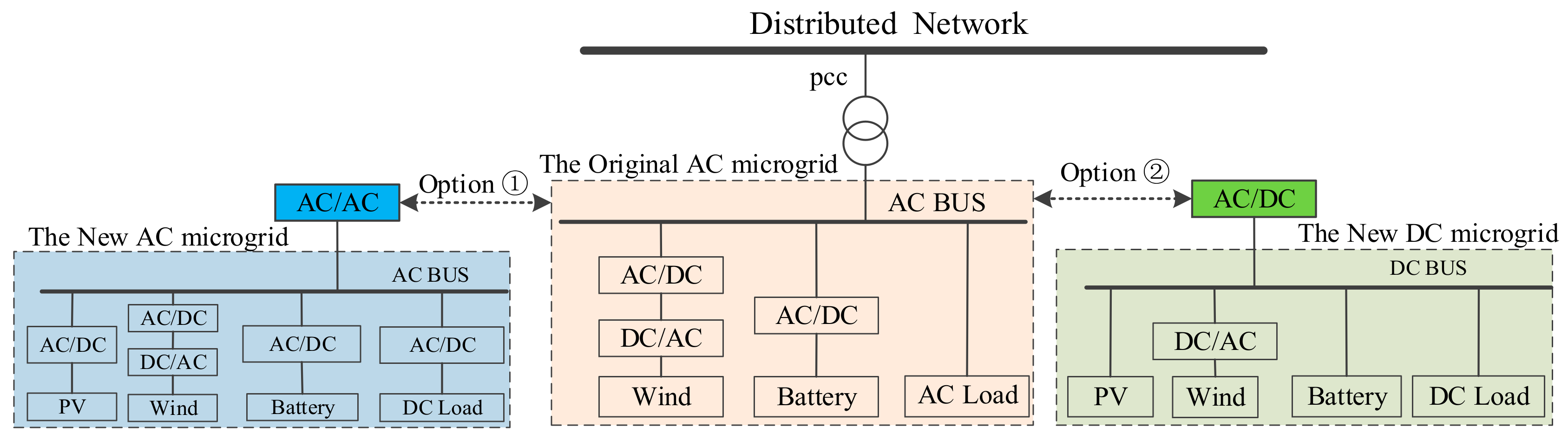
For a distribution network system that includes an AC microgrid, expansion planning is required as the loads increase. Large-capacity DC loads, such as electric vehicles, light emitting diode (LED) lamps, and DC motors, are connected to the microgrid according to certain rules; the DC loads can be connected to AC Bus or DC Bus. Thus, if the original AC microgrid can’t meet load requirements, the original AC microgrid should be expanded, and the expansion planning for the original AC microgrid system includes two options as shown in Figure 1. The new microgrid will have two design method, which are the new AC microgrid and the new DC microgrid. Therefore, the new AC or DC loads can be connected to AC bus or DC bus, making the microgrid system more abundant. Compared with the original microgrid, the new microgrids have more operation modes, and they can accommodate more distributed power resources.
As shown in Figure 1, the new AC microgrid system is connected to the original AC microgrid by the AC bus in Option ①; thus, the new distributed power, AC/DC load, etc. will be connected to the new AC microgrid; in this manner, the new microgrid and the original microgrid form a larger-scale AC microgrid cluster or system. Option ② includes building a new DC microgrid system based on the original AC microgrid by inserting the new DC load into the DC bus and connecting the new AC load to the original AC microgrid, thereby simultaneously increasing the distributed power matching capacity and access mode on the AC or DC bus side, and the AC microgrid and the DC microgrid are then interconnected via a bi-directional AC/DC converter and form AC/DC hybrid microgrid system. This article focuses on the latter.
The AC/DC hybrid microgrid consists of AC sub-microgrids and DC sub-microgrids. The power capacity of an AC sub-microgrid and a DC sub-microgrid is relatively balanced with each respective load; as a result, the power transmission between the AC and DC sub-microgrids is reduced, thereby facilitating the control of the hybrid microgrid. Moreover, the AC or DC sub-microgrids can be networked or operated independently, which increases the flexibility of the operation mode. In the planning of an AC/DC hybrid microgrid, the principles of energy conservation, partition matching, distributed energy complementarity, and guaranteed power quality should be followed; therefore, these design principles must be considered in the expansion planning model and when devising the constraints [4,5,6].
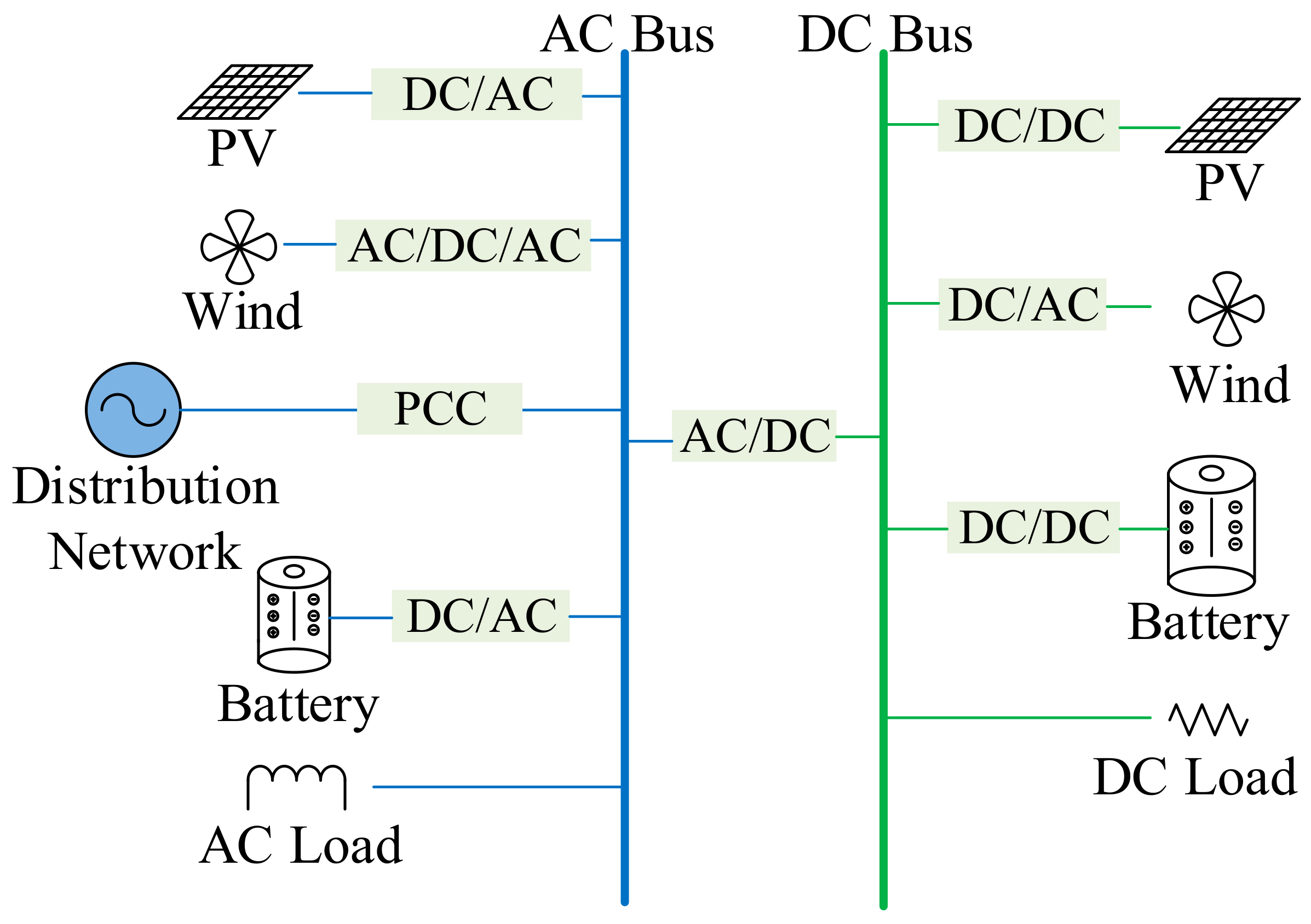
Figure 2 shows a typical grid structure of an AC/DC hybrid microgrid. The hybrid microgrid system connects the AC and DC bus via a bi-directional AC/DC converter, forming AC and DC sub-microgrids. Photovoltaics, wind turbines, energy storage and other power generation units as well as AC and DC loads are connected to AC and DC buses through power electronic converters. As shown in Figure 2, distribution network is connected to the AC Bus, so the power energy transmits between distribution network and AC/DC hybrid microgrid. The point of common coupling (PCC) of the AC/DC hybrid microgrid system and the distribution network is set on the side of the AC sub-microgrid, and through the control of the PCC, the operation model of the AC/DC hybrid microgrid can be changed between grid-connected mode and islanding mode. The AC/DC hybrid microgrid has a simple structure and meets the access requirements of high-density distributed power supply, making the structure suitable for most AC/DC hybrid microgrid systems.
In the development planning of the hybrid AC/DC microgrid, grid-connected distributed power resources must be equipped with inverters, control devices, and reactive power compensation devices, and the considerations of these investment costs are necessary in the planning strategy of AC/DC hybrid microgrids. Therefore, the problem of determining the power capacity and the site of distributed power resources should consider the additional costs for purchasing power electronic equipment. Moreover, distributed power resources and electrical loads should be balanced to reduce network losses; due to the transmission limit of the line, the local balance of “source-network-load” in the microgrid can also improve the reliability of the system’s power supply.
At present, considerable research has been conducted on optimization planning for microgrids and even hybrid AC/DC hybrid microgrids. The concept of an AC/DC hybrid microgrid has been comprehensively reviewed, and the advantages, characteristics, existing problems and research directions of AC/DC hybrid microgrids have been identified [5,6,7]. For the planning and control problems of AC/DC hybrid microgrids, some report in-depth analyses from different perspectives [8,9,10,11]. In [8], authors proposed a control algorithm to achieve smooth power transfers between AC and DC sub-microgrid links and stable system operations under various power generation and load conditions. Using a MATLAB software simulation, the AC/DC hybrid microgrid system was verified to remain stable under the coordinated control scheme. An AC/DC hybrid microgrid contains energy storage and pulsed loads, and a comprehensive frequency and voltage control scheme for an AC/DC hybrid microgrid is introduced consisting of a synchronous generator, a solar simulator, and a bi-directional (AC/DC and DC/DC) converter [10].
Methods of how the DC microgrid or AC/DC hybrid microgrid accesses the distribution network have been discussed in [12,13,14,15]. A method in which certain AC lines are replaced with DC lines was proposed to construct a DC network. Compared with the pre-retrofit project, the construction of the DC microgrid significantly reduced the transmission costs of the AC/DC hybrid microgrids, and further optimized the network loss and voltage stability indicators in [12]. A hybrid planning model for determining distributed energy and power generation systems was proposed, and the type of microgrids was chosen based on economic considerations [13]. The planning objectives mainly included the investment and operating costs of distributed energy resources (DERs), the cost of purchasing energy from the main grid, and the reliability cost. In [14], the optimal planning of a new microgrid-provisional microgrid was studied, and this paper considers the robust optimization method, physical and economic issues, after which a provisional microgrid system was digitally simulated to explore its advantages. A new stochastic programming model for AC/DC hybrid power distribution systems was proposed in [15], and the possibility of each line/bus being AC or DC is considered. The AC/DC hybrid configuration of the bus/line in distribution systems (DSs) is optimized.
The current research focuses on the optimal configuration and cooperative control of an AC microgrid. Scholars have begun to study the route planning of an AC/DC hybrid microgrid. A number of methods in the above research have considered the issues of uncertain supply of distributed power resources, AC/DC power grid interactions, etc. [16,17,18,19,20]. Studies also analyze AC/DC bus and line planning among other issues. However, a method of integrating an AC/DC hybrid microgrid into a distribution network has not been clarified, and few studies have focused on the power capacity and siting of microgrids with high-density distributed power resources. Current research on AC/DC hybrid microgrid planning has not properly considered line expansion and route planning for hybrid microgrids [21,22]. However, the capacity and site of distributed power resources which represent urgent problems haven’t been solved for AC/DC hybrid microgrid systems.
Therefore, this article focuses on expansion planning of an AC/DC hybrid microgrid with high-density distributed power resources. By employing the proposed method, the distributed power supply for local consumption can be maximized, and the microgrid system’s economy, reliability, and flexibility can be improved. This paper establishes the objective function aimed at minimizing the sum of the investment cost, load-loss economic cost, and system loss cost. Besides, the certain constraints are satisfied, including system power balance constraints, system feeder number constraints, distributed power output constraints, etc. In the objective function, line investment costs are considered as a part of microgrid investment costs. The effect of feeder parameters on the distributed power capacity and site configuration results is also analyzed.
The remainder of this work is organized as follows: Section 2 introduces the optimization planning mathematical model of the AC/DC hybrid microgrid. Section 3 presents the method for solving the optimization model. Section 4 employs an actual example to analyze the optimal planning results. Section 5 presents the conclusions.
2. Optimization Planning Model of the AC/DC Hybrid Microgrid
2.1. Objective Function
In the planning of the AC/DC hybrid microgrid, the characteristics of the AC sub-microgrid and the DC sub-microgrid must be considered simultaneously. Therefore, the objective function is different from that of a traditional power system planning model. In this paper, the objective function is to minimize the cost of the AC/DC hybrid microgrid, which includes the investment costs (), load-loss economic costs () and system loss cost:
where is unit loss cost (Dollar/kWh).
- (1)
- Investment costs .
Assume that the number of photovoltaic groups is , group number of wind turbines is , the number of energy storage points is , AC feeder node number is . DC feeder node number is . The mathematical expression of investment cost is:
where is the PV investment cost per MW; is the total capacity of PVs in group i; is the wind power investment cost per MW, is the total capacity of wind turbines in the group j; is the energy storage investment cost per MW; is the total capacity of energy storages in group m; is the unit length AC line investment cost; is the unit length AC line investment cost; and are the line length of the feeder. The microgrid auxiliary equipment costs are denoted , where is the microgrid capacity, including the loads, DGs, and energy storages; a indicates the proportional coefficient between the construction capacity and the construction cost and mainly includes the integrated unit cost of control equipment, reactive power compensation equipment, and harmonic control equipment; b represents the fixed cost of the microgrid construction.
- (2)
- Load-loss economic costs .
Some non-essential loads will be removed in the event of a fault or in some extreme cases. This work uses value of load loss to represent the reliability costs of power supply:
where is the loss of load penalty of the AC sub-microgrid, is the loss of loads of the AC sub-microgrid in time t, is the loss of load penalty of the DC sub-microgrid, and is the loss of load of the DC sub-microgrid in time t.
- (3)
- System loss .
In AC/DC hybrid microgrid planning, high-capacity distributed energy resources will access the hybrid system, and AC or DC sub-microgrids need to be directly supplied with AC load and DC load. Therefore, a large number of converters are connected to the system to achieve energy transfer, voltage conversion, and commutation. During the operation of the AC/DC hybrid microgrid, the converter has a certain conversion efficiency (<100%), so the converter achieves a certain amount of loss during system operation. When the number of inverters in the system increases, the converter losses will become larger, so it is necessary to limit the loss of the inverter and optimize the analysis of the configuration of the inverter, in order to reduce the operating cost of the system. The AC/DC hybrid microgrid system includes AC bus/feeder and DC bus/feeder, so the lines consume a certain amount of energy during energy transfer, which is added in the cost calculation:
where is the power losses of AC and DC lines, and is the converter losses.
2.2. Constraints
According to the technical standards for power grid operation and planning, certain constraints must be satisfied in network topology planning of AC/DC hybrid microgrids, such as system power balance constraints, system feeder number constraints, distributed power output constraints, node voltage deviation constraints, and power supply reliability constraints.
- (1)
- System power balance constraints.
The microgrid system needs to meet the principle of partition matching, that is, DC sub-microgram to meet the power balance constraints at the same time:
where denotes the DC load power consumption, denotes the DC sub-microgram system losses, denotes the wind power in DC side, denotes the PV power in DC side, denotes the energy storage battery power in DC side, its value is negative if the energy storage battery stores energy). Denotes the bi-directional AC-DC converter transmission power (if the AC sub-microgrid transmits the power to the DC part, then the value is positive; otherwise, it is negative).
- (2)
- System feeder number constraints.
In the planning of the AC/DC hybrid microgram system, the access positions of different types of distributed power must be designed, and the number of distributed power branches for the access system must meet certain constraints:
(7) shows the system total feeders number constraints, is the AC sub-microgrid total number of nodes; is the AC side microgrid maximum number of nodes; is the DC sub-microgrid total number of nodes; is the DC sub-microgrid maximum number of nodes.
The number of energy storage point constraints:
(8) shows the number of energy storage point constraints, and is the number of energy storage points; is the maximum number of energy storage points.
- (3)
- Distributed power output constraints
A large number of distributed power are connected in the AC/DC hybrid microgrid system, including photovoltaic, wind, and energy storage. Therefore, the system must satisfy the power output constraints.
Wind and PV output constraints:
where is the maximum PV power; is the maximum wind power.
Energy storage output constraints:
where and are the lower and upper limits of SOC, respectively; and are the maximum charging and discharging power of energy storage device, respectively; is the energy conversion efficiency during the charging process; is the energy conversion efficiency during the discharging process; is the energy storage capacity; and is the time step.
- (4)
- Node voltage deviation constraint
The AC/DC hybrid microgrid contains an AC subsystem and a DC subsystem; thus, its voltage sequence contains both AC and DC components. This paper adopts the AC/DC alternative solution method to calculate the power flow of the AC/DC hybrid microgrid [23,24,25,26] and uses a certain control strategy to maintain the AC bus voltage and DC bus voltage within a certain range:
where and are the AC voltage upper and lower limits of type i, respectively, and and are the DC voltage upper and lower limits of class j, respectively.
- (5)
- Supply reliability constraints
This paper uses the probability of power shortage () to characterize the power supply reliability:
where is the load loss at time t; is load capacity at time t; is the maximum power shortage probability allowed by the hybrid microgrid.
3. Optimization Planning Model Solution
3.1. Optimization Model Solving Method
In the distributed power optimization planning studied in this paper, the site and capacity of different types of distributed power resources to the microgrid are optimized and solved. The variables in the model include the distributed power type, distributed power access location, and distributed power access capacity. The unified variable T is set here to analyze the type, access position, and access capacity of the distributed power resources. The expression is as follows:
where is the type variable, which indicates whether the distributed power is photovoltaic, wind power, or energy storage; is the access location of DG; is the access capacity of the distributed power; and k is the total number of PV, fans, and energy storage groups.
The variables include the distributed power type, the distributed power access location and the distributed power access capacity The planning result , , represents that, in group five, the type of the distributed power resources is PV, its capacity is 200 kW, and the PV is accessing to point ten.
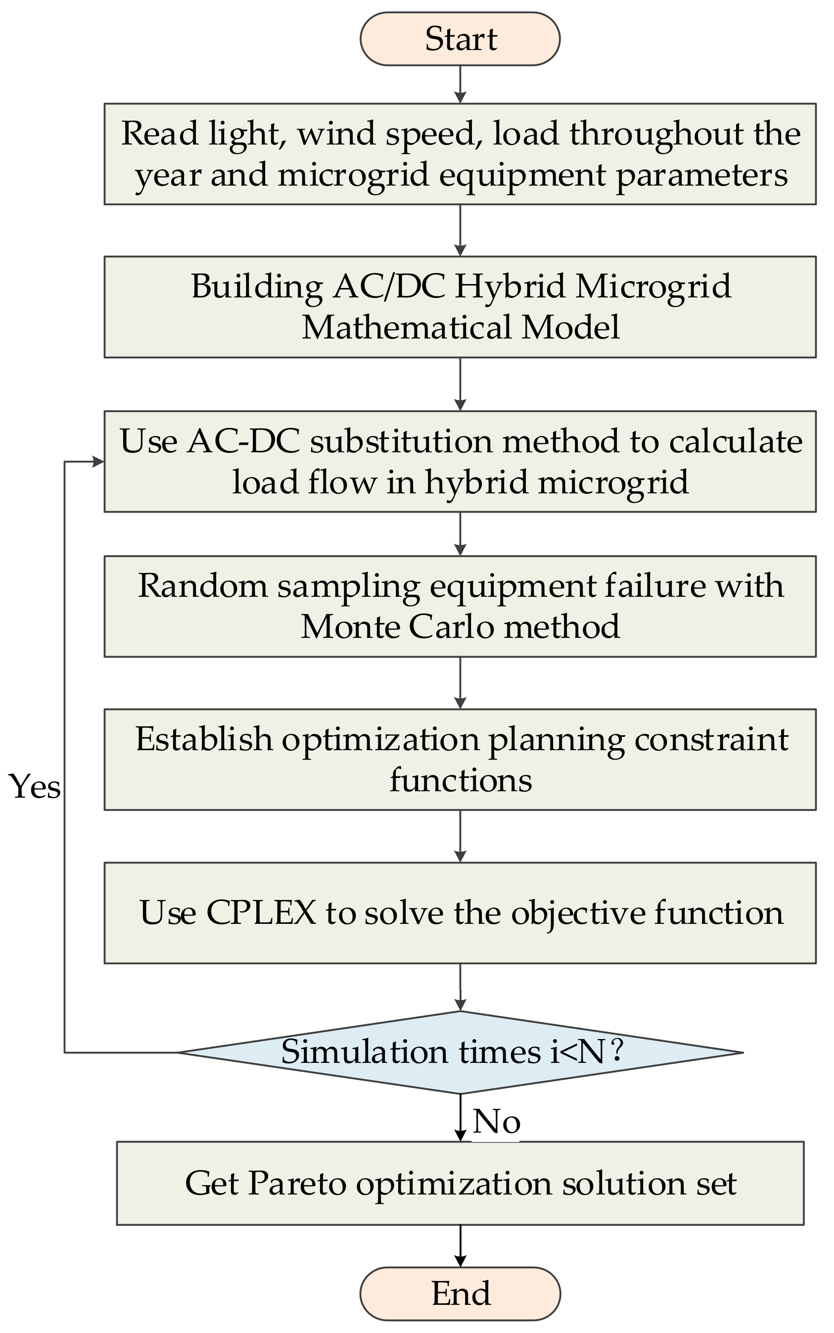
The above model is a mixed integer programming problem. The mathematical model is built as a Java program, and CPLEX’s built-in branch cut plane algorithm is applied to solve the model [27,28]. Since the random failure of the microgrid equipment is considered in the model, the Monte Carlo simulation method is used to simulate the microgrid equipment and line faults. The specific process is shown in Figure 3.
The detailed flowchart of this solution method is as follows:
- Step 1:
- Input data, including light intensity, wind speed, load throughout the year, and microgrid equipment;
- Step 2:
- Build AC/DC hybrid microgrid mathematical model.
- Step 3:
- Using the Monte Carlo method to sample the failure rate, get convergence condition N;
- Step 4:
- Use AC/DC substitution method to calculate load flow in the hybrid microgrid, and attain node voltage value;
- Step 5:
- Sample random equipment failure with Monte Carlo method;
- Step 6:
- Establish optimization planning constraint functions; through load flow calculation and fault sampling, let the system meet the constraint requirements;
- Step 7:
- Use CPLEX to solve the mathematical model, in order to get planning cases;
- Step 8:
- Check the termination condition. If the number of simulations is reached, go to Step 9; otherwise go to Step 4 loop;
- Step 9:
- Get Pareto optimization solution set, used as the original data of Section 3.2.
3.2. Optimal Compromise Solution
In order to select the optimal solution from the Pareto optimal solution set, the fuzzy membership function is used here. The degree of membership is used to reflect the degree of satisfaction of the decision maker with respect to the optimization of the goal, and the fuzzy membership of each objective function is integrated to find the optimal solution. Define the fuzzy membership function [29,30] as:
where is the value of the objective function i and and are the upper and lower limits of the objective function value, respectively.
When , the value of the objective function is the worst; when , the objective function value is the best. For each solution in the Pareto optimal solution set, its normalized satisfaction value is obtained according to Equation (14), and the solution with the highest satisfaction value is the optimal compromise solution:
where is the standardized satisfaction value and m is the number of objective functions to be optimized.
After the Pareto optimal solution set is calculated, the optimal solution should be selected to provide an optimal planning plan. The fuzzy membership function expresses the satisfaction with each objective function in the Pareto optimal set. The planners can comprehensively compare the satisfaction of each solution set by the fuzzy membership, and a most satisfactory planning result can be obtained.
4. Example Verification and Discussion
4.1. Example System Description
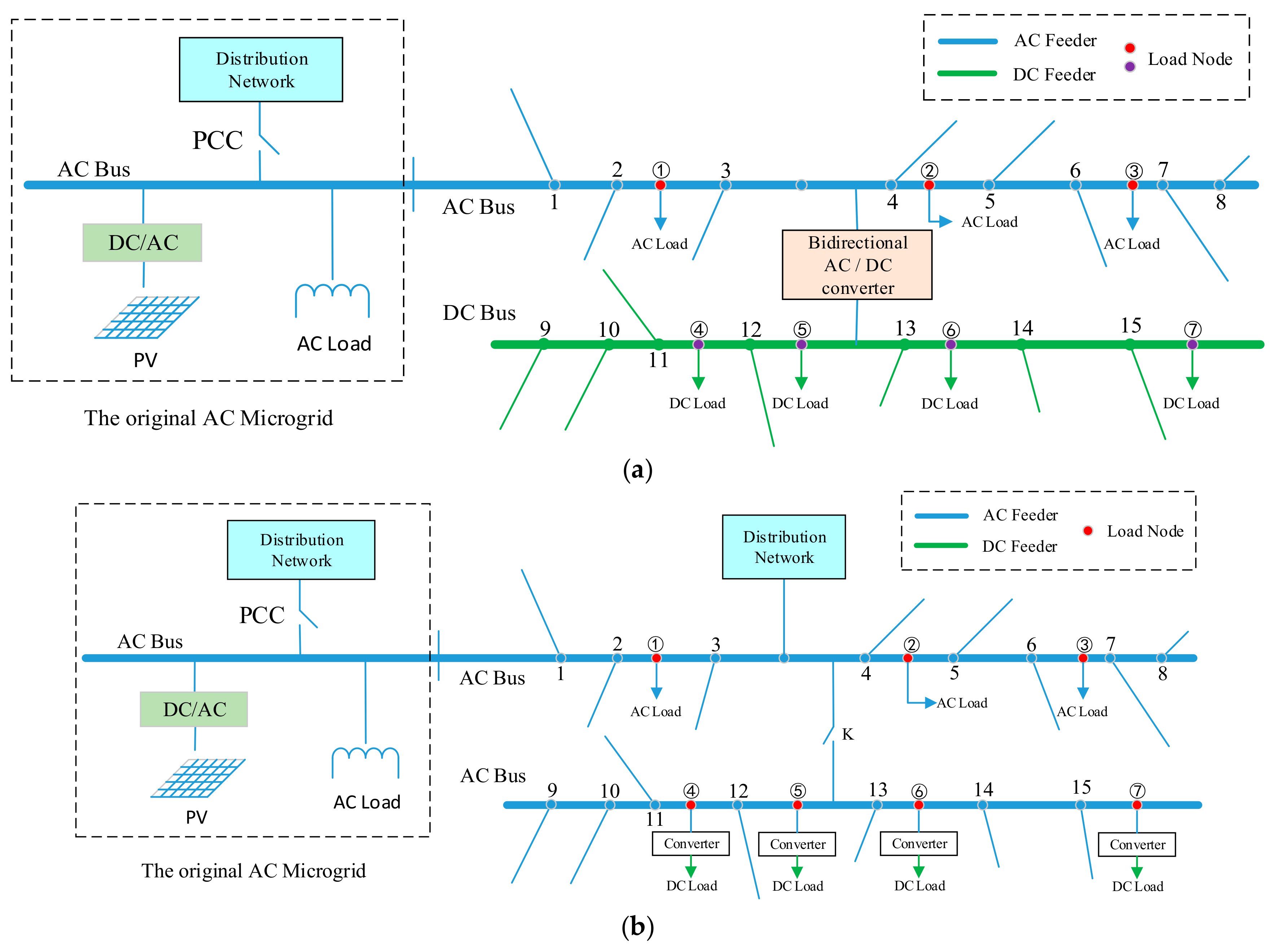
Based on the abovementioned optimization planning model, this paper uses an actual AC microgrid system as an example. In the original AC microgrid system, to meet the demand for load growth, an expansion plan for the microgrid must be implemented, and then the newly planned microgrid will be connected to the original microgrid to form a large microgrid system and communicate with the distribution network. There are two types of expansion plans for the original microgrid: the AC/DC hybrid microgrid expansion plan (Case I) and the pure AC microgrid expansion plan (Case II). These plans are shown in Figure 4.
According to Figure 4a, a total of 15 distributed power access points are included in the extension system that can be connected to different types of distributed power resources (PV, wind turbine, energy storage) and seven load nodes with three AC load access points and four DC load access points are observed. According to the local load development situation, the future load mostly consists of DC loads, such as lighting load, DC motor, and electric vehicle charging pile. Therefore, the load is accessed in the AC microgrid through the converter, and in the AC/DC hybrid microgrid, the load is connected to the DC side. Here, the ratio of new DC load to the new total load is referred to as R:
where is DC load capacity; is total load on the microgrid.
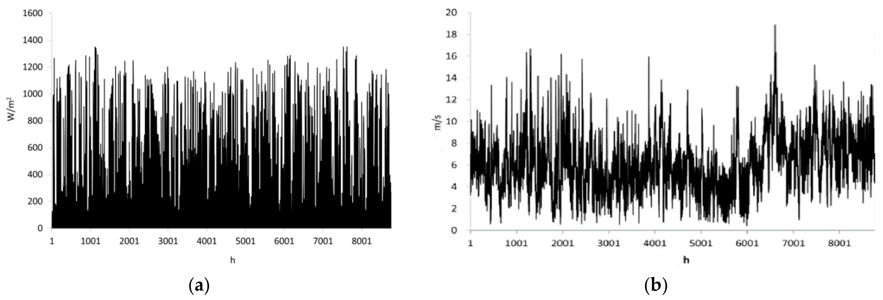
In this manner, the influence of the change in the proportion of DC load on the planning results will be discussed. Based on the AC microgrid, this paper considers factors such as the local consumption of distributed energy, load development requirements, and route planning choices to perform microgrid distributed power capacity and site optimization planning. The light intensity and wind speed year data are shown in Figure 5; and the technical and economic parameters are shown in Table 1. All of the nomenclatures will be explained in Appendix A.
4.2. Case I Distributed Power Capacity and Site Optimization Planning
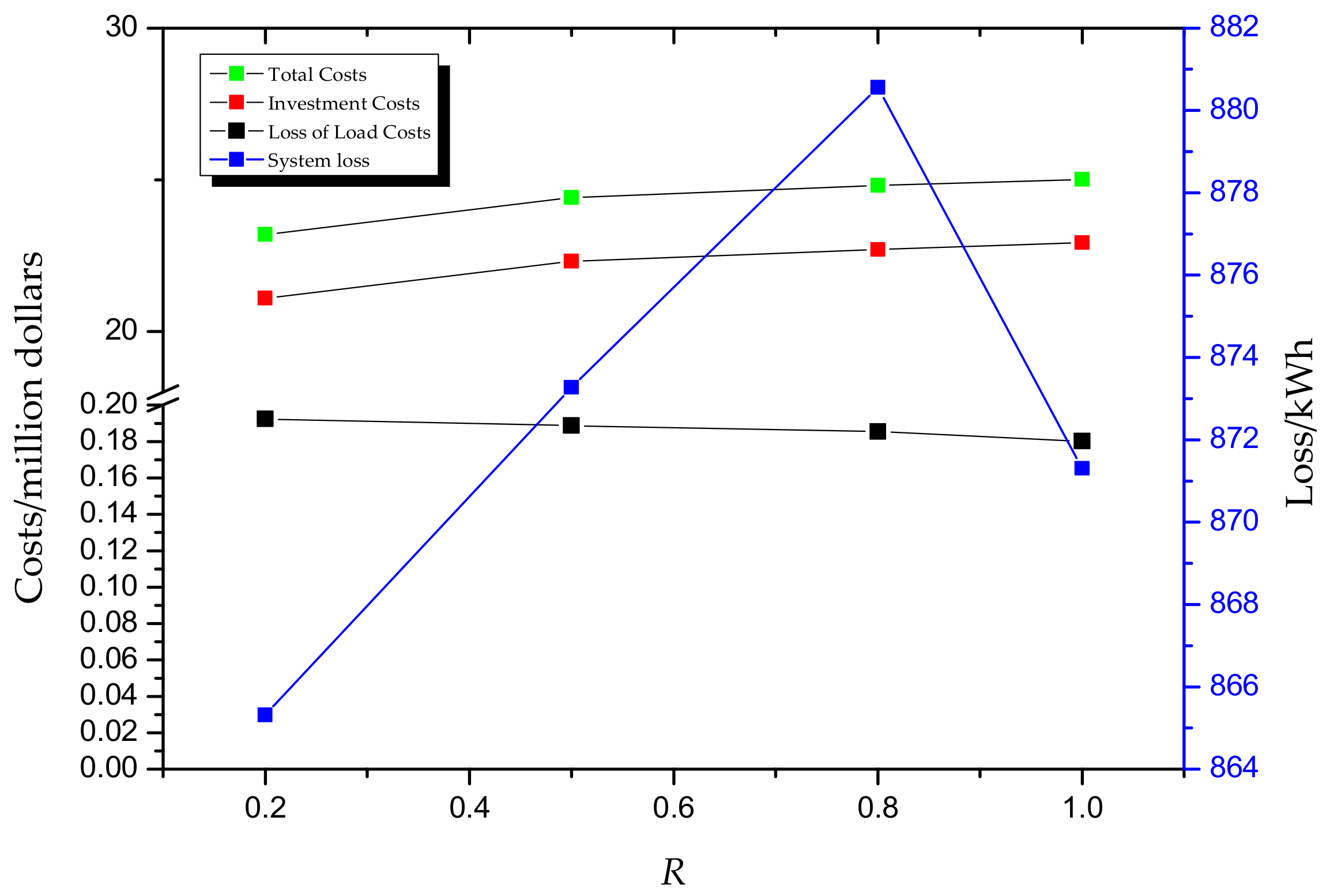
In Case I, the microgrid system is an AC/DC hybrid microgrid, including an AC sub-microgrid and a DC sub-microgrid. The new DC load is directly connected to the DC bus, and a part of the distributed power will be connected to the DC sub-microgrid. Figure 6 shows the economic analysis results of AC/DC hybrid expansion planning.
It can be seen from Figure 6:
- (1)
- The economic factors associated with expansion planning for the AC/DC hybrid microgrid system are mainly determined by the investment costs, which account for approximately 90% of the total costs; therefore, the rational planning of distributed power access is the key to reducing planning costs.
- (2)
- As the proportion of DC load increases, the investment costs gradually increase, but the growth rate slows down. As the scale of the DC microgrid increases, the proportion of investment costs in the DC portion of the system decreases and the cost growth rate decreases.
- (3)
- Load-loss economic costs and system losses increase first and then decrease as R increases. Thus, the access to DC loads increases, the use of converters decreases, the system reliability increases, and the energy conversion rate increases.
Table 2 shows the optimal planning results of the AC/DC hybrid microgrid distributed power resources supply under Case I. In the table, each cell represents type and capacity of distributed power; for example, when R = 0.5, the distributed power connected to node 5 is PV, and the capacity of PV is 223 kW. With the change of R, the optimal configuration results are different. The following results are outlined in the table.
- (1)
- In the distributed power source selection, the investment costs of photovoltaic power are low and solar energy resources at the project location are superior to wind energy. Thus, PV power dominates in the optimized configuration.
- (2)
- When R increases and the load demand of the AC microgrid decreases, the configuration of wind power will be reduced first. Then, the energy storage will be reduced, and ultimately the PV configuration will be reduced. Because the wind output is small and highly random, the wind power configuration should be reduced first, and because the cost of energy storage is greater than the cost of PV, energy storage should also be reduced in the configuration first.
- (3)
- When R ≥ 0.8 and the distributed power accesses the maximum capacity of the line in the DC sub-microgrid, certain energy that cannot meet the DC load demand must be obtained from the AC sub-microgrid; thus, the energy balance of the DC sub-microgrid is achieved by increasing the interactive power of the bi-directional AC-DC converters.
4.3. Comparison of the Distributed Power Capacity and Site Planning Results between Case I and Case II
Under the condition of different R values, the results of the expansion planning for the AC microgrid and the AC/DC hybrid microgrid are analyzed and the economic costs of different types of microgrid planning are obtained. According to Table 3, for the same proportion of DC load conditions, the AC microgrid expansion planning and the AC/DC hybrid microgrid expansion planning results are quite different.
The optimization planning results for the two expansion plans are shown in Table 3.
- (1)
- From the perspective of investment costs, as the proportion of DC load increases, the investment costs of both options increase; however, the growth rate of the AC/DC hybrid microgrid is lower than that of the AC microgrid. In the initial construction of an AC/DC hybrid microgrid, the scale is small and the investment is high; in addition, when the scale of the DC sub-microgrid increases, the investment cost growth decreases.
- (2)
- In terms of load-loss economic costs, the cost of Case II is higher because a large number of converters are required when the DC load is connected to the AC microgrid and the reliability of the load power supply is reduced.
- (3)
- Regarding the total cost, when R = 0.5, the two cases are basically the same; and when R > 0.5, the cost of AC/DC hybrid microgrid is lower. Thus, the solution in Case I has a higher advantage than that in Case II.
4.4. Effect of Line Parameters on the Distributed Power Capacity and Site Configuration Result
This paper considers the influence of line factors on the distributed power optimal configuration of the AC/DC hybrid microgrid. From the perspective of the DC feeder and the DC bus, the effects of the factors on the optimal planning results are analyzed:
- (1)
- Effect of DC Feeder on the optimized configuration results
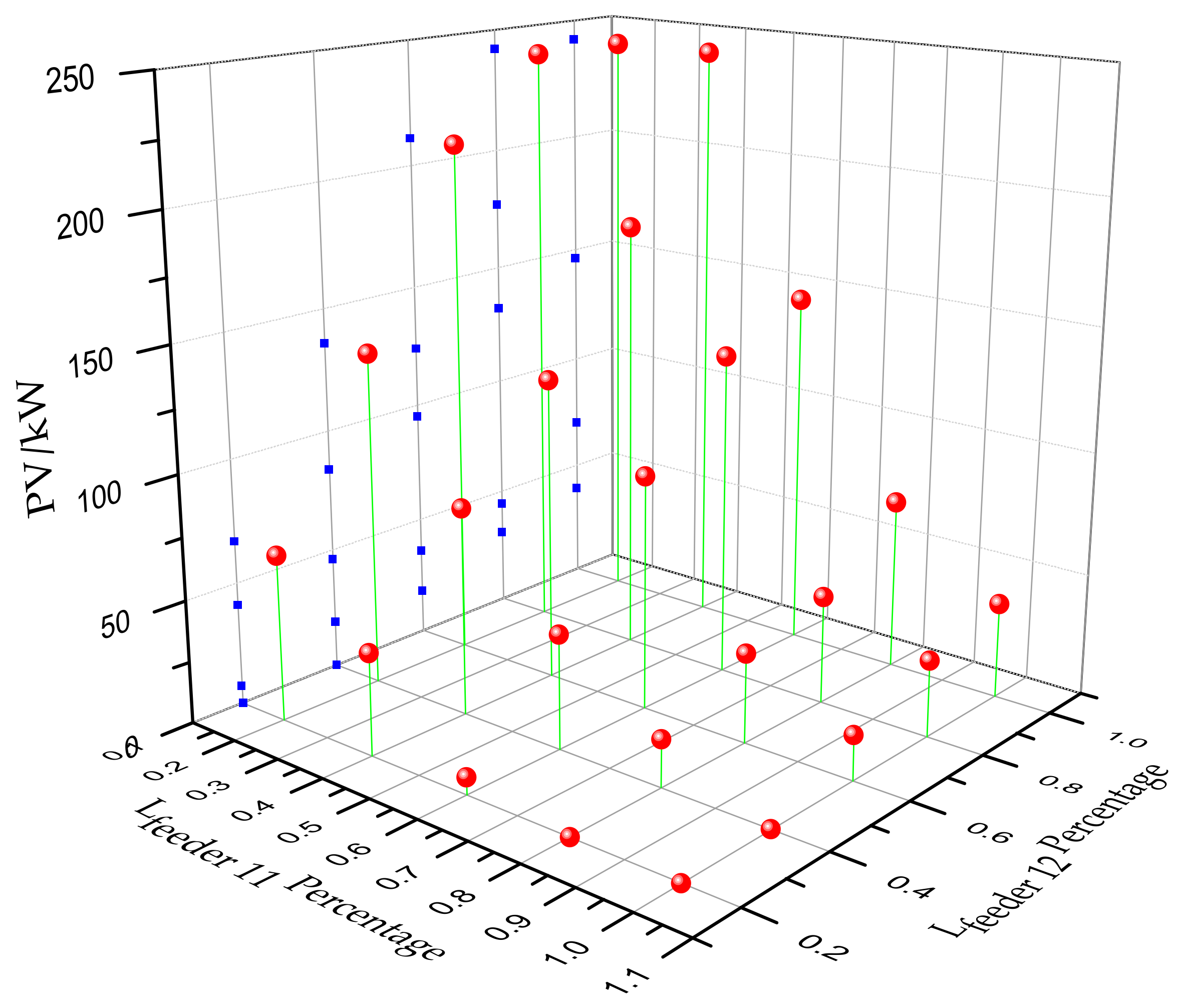
Under the conditions of Case I and R = 0.5, the DC load node ④ is selected as the research object. By changing the length parameters of feeder 11 and feeder 12, the optimal configuration result of the distributed power is analyzed. By changing the standard values of the lengths of feeders 11 and 12, the planning model is used for the optimal planning of the distributed power. The results of the configuration of feeder 11 accessing the photovoltaic capacity are shown in Figure 7.
Figure 7 shows that when the length of a certain feeder increases, the power supply capacity of the feeder is reduced to decrease the feeder loss. In addition, when feeder 11 and feeder 12 are changed by the same ratio, the power capacity configured in feeder 11 is found to change little because for the two feeders, the feeder 12 node and the load point 4 have smaller bus lengths that dominate the power configuration.
- (2)
- Effect of DC bus on optimized configuration results
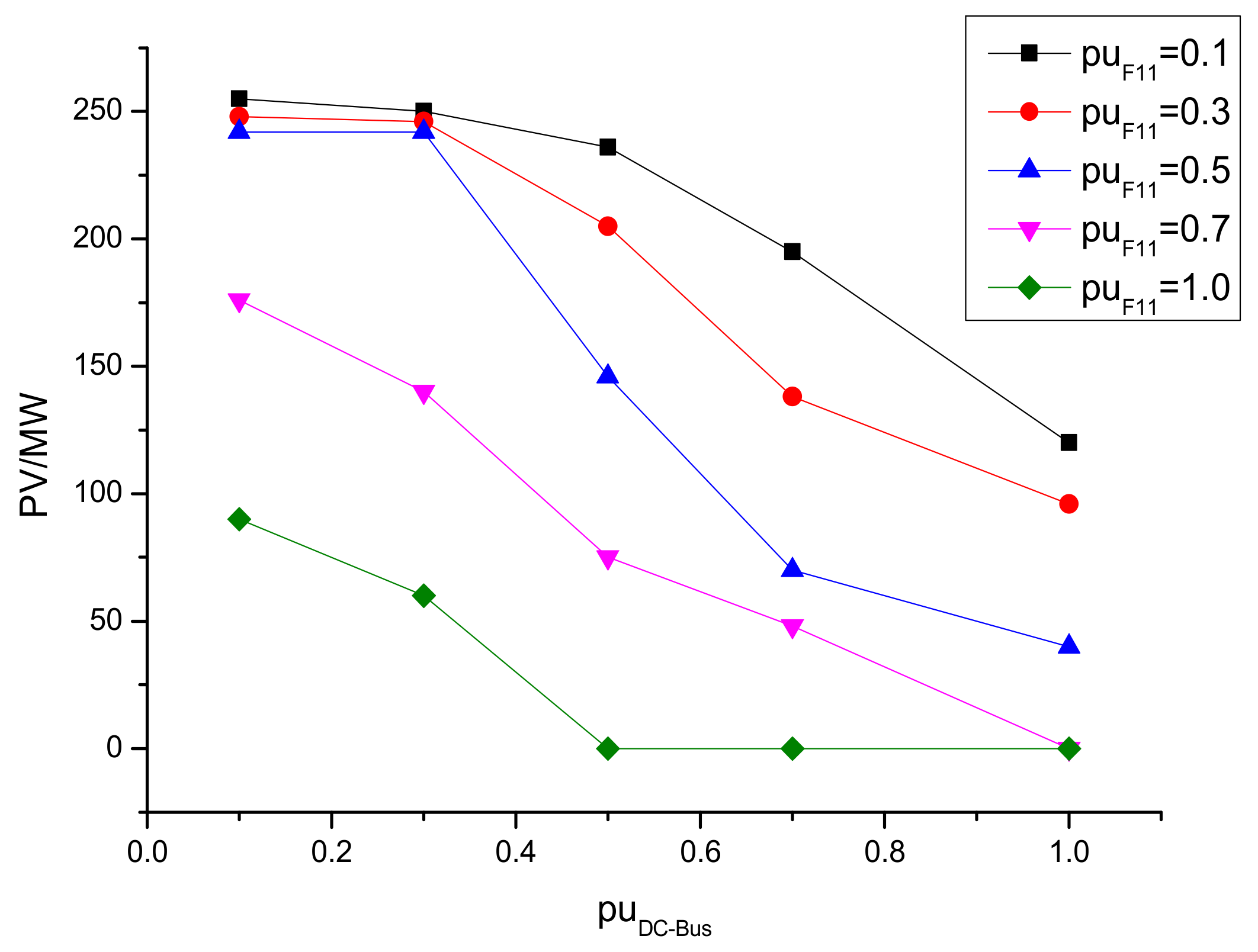
Under the conditions of Case I and R = 0.5, the DC load node ④ is selected as the research object. By changing the DC bus length parameters between the feeder 11 node and the DC load node ④, the changes of the distributed power optimized configuration results are analyzed. By changing the unit length of the DC bus, the results of the configuration of feeder 11 accessing the photovoltaic capacity are shown in Figure 8.
Figure 8 shows that:
- (1)
- When the feeder length is fixed, the distributed power capacity decreases as the bus length increases.
- (2)
- When and , photovoltaic capacity of access feeder 11 is greatly reduced. When and the length of the DC bus decreases, the increase in access PV capacity is less, limited by feeder capacity and load requirements. When , the bus length has a greater impact on the economic cost, and the distributed power configuration capacity is reduced rapidly.
- (3)
- When , the influence of the feeder length on the optimized configuration result increases, and the DC bus factor plays a minor role.
4.5. Effect of Interactive Power Cap on the Configuration Result
Under the Case I network architecture, for the same R values, different interaction power caps between the microgrid and the distribution network will also have an impact on optimizing the configuration results. Table 4 shows the optimal configuration results for different interactive power cap (IPC) conditions when R = 0.5.
As the interaction power caps increase between the microgrid and the distribution network, the maximum interactive power also increases and the power flow between the AC/DC hybrid microgrid and the distribution network becomes frequent. An analysis of the optimal configuration of the distributed power easily shows that as the interaction power caps gradually increases, the distributed power capacity configured in the DC sub-microgrid increases. Moreover, due to the low configuration cost of the DC microgrid, the distributed power resources connected to the DC sub-microgrid can increase by increasing interactive power upper limit with the distribution network.
5. Conclusions
Due to the variety, intermittency of DGs, and complexity of distribution network structures, it’s hard to meet the planning requirements for a microgrid to access a distribution network by simply considering the characteristics of a distributed power supply. This paper describes the addition of the lines investment into the optimal planning model of an AC/DC hybrid microgrid to determine the optimal access scheme of distributed power.
This work proposes a planning model, taking the line factors for the distributed power capacity and the site of the AC/DC hybrid microgrid into account. The proposed model integrates a number of factors, such as power investment costs, line expansion, and load reliability. The proposed model includes AC/DC bus access points in the planning area as well as the planned capacity and site of high-density distributed power access to the microgrid to both reduce the cost of the entire microgrid system and improve the reliability. In practical engineering examples, this paper used the CPLEX solver to optimize the model and comparatively analyses the AC microgrid and AC/DC hybrid microgrid. The influences of the line length and the different IPCs on the optimization configuration results are analyzed.
The main contribution of this paper is that, in the AC/DC hybrid microgrid planning, the factors such as line cost and access point of the distribution network are taken into account. The optimal distributed power resources capacity and site planning can be obtained under different line expansion scenarios in order to realize local consumption. Therefore, the proposed model can be applied to actual projects.
Author Contributions
H.P. and M.D. conceived and designed the experiments; H.P. performed the experiments; H.P. analyzed the data; R.B. and A.C. provided the experimental environment; and H.P., L.S. and S.S. wrote the paper. All authors have contributed to the editing and proofreading of this paper.
Funding
This work is supported by grants from the National 863 Program of China (2015AA050104).
Conflicts of Interest
The authors declare that they have no conflicts of interest.
Appendix A
Nomenclature will be explained in this Table A1.

Table A1.
Nomenclature.
| Name | Meaning | Unit | Name | Meaning | Unit |
|---|---|---|---|---|---|
| investment costs | Dollar | load-loss economic costs | Dollar | ||
| system losses | kWh | the loss cost of the unit charge | Dollar/kWh | ||
| the number of PV groups | / | group number of wind | / | ||
| the number of energy storage points | / | feeder node number | / | ||
| AC feeder node number | / | DC feeder node number | / | ||
| i | PV group number | / | j | wind group number | / |
| m | energy storage group number | / | n | feeder number | / |
| the total capacity of PVs in group i | kW | the total capacity of wind turbines in the group j | kW | ||
| the total capacity of energy storages in group m | kW | the line length of the feeder n | km | ||
| microgrid capacity | kW | a | the proportional coefficient | / | |
| b | the fixed cost of the microgrid construction | Dollar | t | operation hours | minute |
| the loss of load penalty of the AC sub-microgrid | Dollar/kWh | the loss of loads of the AC sub-microgrid in time t | kW | ||
| the loss of load penalty of the DC sub-microgrid | Dollar/kWh | the loss of load of the DC sub-microgrid in time t | kW | ||
| the power losses of AC and DC lines | kWh | the converter losses | kWh | ||
| system load power consumption | kW | system loss | kW | ||
| wind power | kW | PV power | kW | ||
| energy storage battery power | kW | interactive power between AC/DC hybrid microgrid systems and the distribution networks | kW | ||
| the DC load power consumption | kW | the DC sub-microgram system losses | kW | ||
| wind power in DC side | kW | PV power in DC side | kW | ||
| energy storage battery power in DC side | kW | the bi-directional AC-DC converter transmission power | kW | ||
| AC sub-microgrid total number of nodes | / | AC side microgrid maximum number of nodes | / | ||
| DC sub-microgrid total number of nodes | / | DC sub-microgrid maximum number of nodes | / | ||
| the maximum number of energy storage points | / | the maximum PV power | kW | ||
| the maximum wind power | kW | SOC | State of charge | % | |
| the lower limits of SOC | % | the upper limits of SOC | % | ||
| maximum discharging power of energy storage device | kWh | maximum charging power of energy storage device | kWh | ||
| the energy conversion efficiency during the charging process | % | the energy conversion efficiency during the discharging process | % | ||
| energy storage capacity | kW | the time step | minute | ||
| the AC voltage lower limits of type i | kV | the AC voltage upper limits of type i | kV | ||
| the DC voltage lower limits of type i | kV | the DC voltage lower limits of type i | kV | ||
| the probability of power shortage | % | the load loss in time t | kW | ||
| load capacity in time t | kW | the maximum power shortage probability | kW |
References
- Planas, E.; Andreu, J.; Gárate, J.I.; de Alegría, I.M.; Ibarra, E. AC and DC technology in microgrids: A review. Renew. Sustain. Energy Rev. 2015, 43, 726–749. [Google Scholar] [CrossRef]
- Nejabatkhah, F.; Li, Y.W. Overview of Power Management Strategies of Hybrid AC/DC Microgrid. IEEE Trans. Power Electron. 2015, 30, 7072–7089. [Google Scholar] [CrossRef]
- Gupta, A.; Doolla, S.; Chatterjee, K. Hybrid AC-DC Microgrid: Systematic Evaluation of Control Strategies. IEEE Trans. Smart Grid 2017, 9. [Google Scholar] [CrossRef]
- Justo, J.J.; Mwasilu, F.; Ju, L.; Jung, J.W. AC-microgrids versus DC-microgrids with distributed energy resources: A review. Renew. Sustain. Energy Rev. 2013, 24, 387–405. [Google Scholar] [CrossRef]
- Unamuno, E.; Barrena, J.A. Hybrid ac/dc microgrids—Part I: Review and classification of topologies. Renew. Sustain. Energy Rev. 2015, 52, 1251–1259. [Google Scholar] [CrossRef]
- Unamuno, E.; Barrena, J.A. Hybrid ac/dc microgrids—Part II: Review and classification of control strategies. Renew. Sustain. Energy Rev. 2015, 52, 1123–1134. [Google Scholar] [CrossRef]
- Ackermann, T.; Knyazkin, V. Interaction between distributed generation and the distribution network: Operation aspects. In Proceedings of the IEEE/PES Transmission and Distribution Conference and Exhibition, Yokohama, Japan, 6–10 October 2002. [Google Scholar]
- Liu, X.; Wang, P.; Loh, P.C. A Hybrid AC/DC Microgrid and Its Coordination Control. IEEE Trans. Smart Grid 2011, 2, 278–286. [Google Scholar] [CrossRef] [Green Version]
- Baboli, P.T.; Shahparasti, M.; Moghaddam, M.P.; Haghifam, M.R.; Mohamadian, M. Energy management and operation modelling of hybrid AC–DC microgrid. IET Gener. Transm. Distrib. 2014, 8, 1700–1711. [Google Scholar] [CrossRef]
- Ma, T.; Cintuglu, M.H.; Mohammed, O.A. Control of Hybrid AC/DC Microgrid Involving Storage, Renewable Energy and Pulsed Loads. IEEE Trans. Ind. Appl. 2015, 53, 567–575. [Google Scholar] [CrossRef]
- Wang, P.; Liu, X.; Jin, C.; Loh, P.; Choo, F. A hybrid AC/DC micro-grid architecture, operation and control. In Proceedings of the 2011 IEEE Power and Energy Society General Meeting, Detroit, MI, USA, 24–29 July 2011; pp. 1–8. [Google Scholar]
- Yang, Y.; Wang, X.; Luo, J.; Duan, J.; Gao, Y.; Li, H.; Xiao, X. Multi-Objective Coordinated Planning of Distributed Generation and AC/DC Hybrid Distribution Networks Based on a Multi-Scenario Technique Considering Timing Characteristics. Energies 2017, 10, 2137. [Google Scholar] [CrossRef]
- Lotfi, H.; Khodaei, A. AC versus DC Microgrid Planning. IEEE Trans. Smart Grid 2015, 8, 296–304. [Google Scholar] [CrossRef]
- Khodaei, A. Provisional Microgrid Planning. IEEE Trans. Smart Grid 2017, 8, 1096–1104. [Google Scholar] [CrossRef]
- Ahmed, H.M.A.; Eltantawy, A.B.; Salama, M.M.A. A Planning Approach for the Network Configuration of AC-DC Hybrid Distribution Systems. IEEE Trans. Smart Grid 2016, 9. [Google Scholar] [CrossRef]
- Loh, P.C.; Li, D.; Chai, Y.K.; Blaabjerg, F. Autonomous Operation of Hybrid Microgrid with AC and DC Subgrids. IEEE Trans. Power Electron. 2012, 28, 2214–2223. [Google Scholar] [CrossRef]
- Yang, H.X.; Zhou, W.; Lu, L.; Fang, Z. Optimal sizing method for stand-alone hybrid solar-wind system with LPSP technology by using genetic algorithm. Sol. Energy 2008, 82, 354–367. [Google Scholar] [CrossRef]
- Gao, L.; Liu, Y.; Ren, H.; Guerrero, J.M. A DC Microgrid Coordinated Control Strategy Based on Integrator Current-Sharing. Energies 2017, 10, 1116. [Google Scholar] [CrossRef]
- Bae, I.S.; Kim, J.O. Reliability Evaluation of Distributed Generation Based on Operation Mode. IEEE Trans. Power Syst. 2007, 22, 785–790. [Google Scholar] [CrossRef]
- Lu, X.; Wan, J. Modeling and Control of the Distributed Power Converters in a Standalone DC Microgrid. Energies 2016, 9, 217. [Google Scholar] [CrossRef]
- Sheng, W.X.; Ye, X.S.; Liu, K.Y.; Meng, X.L. Optimal allocation between distributed generations and micro-grid based on NSGA-II algorithm. Proc. CSEE 2015, 35, 4655–4662. [Google Scholar] [CrossRef]
- Yoon, S.G.; Kang, S.G. Economic Microgrid Planning Algorithm with Electric Vehicle Charging Demands. Energies 2017, 10, 1487. [Google Scholar] [CrossRef]
- Tong, S.; Miu, K.N. A network-based distributed slack bus model for DGs in unbalanced power flow studies. IEEE Trans. Power Syst. 2005, 20, 835–842. [Google Scholar] [CrossRef]
- Yan, W.; Liu, F.; Chung, C.Y.; Wong, K.P. A hybrid genetic algorithm-interior point method for optimal reactive power flow. IEEE Trans. Power Syst. 2006, 21, 1163–1169. [Google Scholar] [CrossRef]
- Hajian, M.; Rosehart, W.D.; Zareipour, H. Probabilistic Power Flow by Monte Carlo Simulation with Latin Supercube Sampling. IEEE Trans. Power Syst. 2013, 28, 1550–1559. [Google Scholar] [CrossRef]
- Pereira, M.V.F.; Maceira, M.E.P.; Oliveira, G.C.; Pinto, L.M.V.G. Combining analytical models and Monte-Carlo techniques in probabilistic power system analysis. IEEE Trans. Power Syst. 2002, 7, 265–272. [Google Scholar] [CrossRef]
- The International Business Machines Corporation (IBM). IBM ILOG CPLEX User’s Manual; IBM: New York, NY, USA, 2015. [Google Scholar]
- Li, Y.; Yang, Z.; Li, G.; Zhao, D.; Tian, W. Optimal Scheduling of an Isolated Microgrid with Battery Storage Considering Load and Renewable Generation Uncertainties. IEEE Trans. Ind. Electron. 2018, 99. [Google Scholar] [CrossRef]
- Liu, W.; Jing, W.; Chang, X.; Weizhou, W.; Chen, L. Multi-objective Optimal Method Considering Wind Power Accommodation Based on Source-load Coordination. Proc. CSEE 2015, 35, 1079–1088. [Google Scholar] [CrossRef]
- Peng, S.U.; Liu, T.Q.; Zhao, G.B.; Zhang, J. An Improved Particle Swarm Optimization Based Multi-Objective Load Dispatch Under Energy Conservation Dispatching. Power Syst. Technol. 2009, 33, 48–53. [Google Scholar] [CrossRef]
Figure 1.
Expansion planning of microgrids.

Figure 2.
AC/DC hybrid microgrid typical structure.

Figure 3.
Optimization solution flow chart.

Figure 4.
Schematic diagram of the microgrid extended grid structure in a certain area (a) Case I; (b) Case II.
Figure 4.
Schematic diagram of the microgrid extended grid structure in a certain area (a) Case I; (b) Case II.

Figure 5.
The light intensity and wind speed year data (a) annual light intensity curve; (b) wind speed curve.
Figure 5.
The light intensity and wind speed year data (a) annual light intensity curve; (b) wind speed curve.

Figure 6.
Trend analysis of the distributed power planning economic scenario in Case I.

Figure 7.
Optimized configuration results for different feeder parameters.

Figure 8.
Optimized configuration results for different DC bus parameters.

Table 1.
Technical and economic parameters.
| Parameter Name | Value | Parameter Name | Value |
|---|---|---|---|
| 20.3/(Million Dollar/MW) | 18.8/(Million Dollar/km) | ||
| 15.6/(Million Dollar/MW) | 23.5/(Million Dollar/km) | ||
| 15.6/(Million Dollar/MW) | 6 | ||
| a | 7.2/(Million Dollar/MW) | 5 | |
| b | 0.78/Million Dollar | 4 |
Table 2.
Case I distributed power capacity and site optimization planning (type (capacity)).
| R | 0.2 | 0.5 | 0.8 | 1 | |
|---|---|---|---|---|---|
| NODE | |||||
| 2 | PV (223 kW) | PV (221 kW) | PV (210 kW) | -- | |
| 4 | Bat (50 kW) | Bat (50 kW) | Bat (25 kW) | -- | |
| 5 | PV (231 kW) | PV (223 kW) | -- | PV (236 kW) | |
| 6 | Wind (50 kW) | Wind (50 kW) | Wind (20 kW) | -- | |
| 7 | Wind (24 kW) | -- | -- | -- | |
| 11 | -- | PV (40 kW) | PV (248 kW) | PV (250 kW) | |
| 12 | PV (233 kW) | PV (242 kW) | PV (245 kW) | PV (250 kW) | |
| 13 | Bat (12 kW) | Bat (24 kW) | Bat (50 kW) | Bat (60 kW) | |
| 14 | -- | PV (239 kW) | PV (242 kW) | PV (250 kW) | |
| 15 | -- | Wind (20 kW) | Wind (50 kW) | Wind (60 kW) | |
Table 3.
Comparison of the two planning schemes under different R conditions.
| R | Total Cost/$ | Investment Costs/$ | Load-loss Economic Costs/$ | System Loss/kWh |
|---|---|---|---|---|
| 0.2 | 234,292.89 | 214,385.55 | 2021.87 | 868.72 |
| 218,447.06 | 196,623.48 | 2231.75 | 880.51 | |
| 0.5 | 248,219.61 | 225,425.99 | 1911.36 | 874.17 |
| 247,897.22 | 225,991.36 | 2231.75 | 879.36 | |
| 0.8 | 250,545.07 | 230,888.87 | 1889.37 | 882.03 |
| 255,815.41 | 234,250.79 | 2238.03 | 887.15 | |
| 1 | 254,435.09 | 232,601.25 | 1862.67 | 873.52 |
| 263,438.58 | 240,597.61 | 2253.74 | 892.81 |
Note: Light Blue background is Case I, White background is Case II.
Table 4.
Optimization planning results under different interactive power caps.
| IPC/kW | AC Sub-Microgrid | DC Sub-Microgrid | Max Interactive Power/kW | ||||
|---|---|---|---|---|---|---|---|
| PV/kW | Wind/kW | Bat | PV/kW | Wind/kW | Bat | ||
| 100 | 462 | 50 | 50 | 485 | 20 | 24 | 99.6 |
| 105 | 446 | 50 | 50 | 478 | 20 | 24 | 104.3 |
| 110 | 314 | 40 | 24 | 582 | 30 | 50 | 109.5 |
| 115 | 295 | 25 | 12 | 593 | 50 | 50 | 114.1 |
| 120 | 254 | 15 | 12 | 637 | 50 | 55 | 119.8 |
© 2018 by the authors. Licensee MDPI, Basel, Switzerland. This article is an open access article distributed under the terms and conditions of the Creative Commons Attribution (CC BY) license (http://creativecommons.org/licenses/by/4.0/).
Share and Cite
MDPI and ACS Style
Pan, H.; Ding, M.; Chen, A.; Bi, R.; Sun, L.; Shi, S. Research on Distributed Power Capacity and Site Optimization Planning of AC/DC Hybrid Micrograms Considering Line Factors. Energies 2018, 11, 1930. https://doi.org/10.3390/en11081930
AMA Style
Pan H, Ding M, Chen A, Bi R, Sun L, Shi S. Research on Distributed Power Capacity and Site Optimization Planning of AC/DC Hybrid Micrograms Considering Line Factors. Energies. 2018; 11(8):1930. https://doi.org/10.3390/en11081930
Chicago/Turabian StylePan, Hao, Ming Ding, Anwei Chen, Rui Bi, Lei Sun, and Shengliang Shi. 2018. "Research on Distributed Power Capacity and Site Optimization Planning of AC/DC Hybrid Micrograms Considering Line Factors" Energies 11, no. 8: 1930. https://doi.org/10.3390/en11081930
Note that from the first issue of 2016, this journal uses article numbers instead of page numbers. See further details here.