Article

Reactive Power and Current Harmonic Control Using a Dual Hybrid Power Filter for Unbalanced Non-Linear Loads

by
Leonardo Rodrigues Limongi
,
Fabricio Bradaschia
,
Calebe Hermann de Oliveira Lima
and
Marcelo Cabral Cavalcanti
*
Department of Electrical Engineering, Federal University of Pernambuco, Recife 50740-550, Brazil
*
Author to whom correspondence should be addressed.
Energies 2018, 11(6), 1392; https://doi.org/10.3390/en11061392
Submission received: 25 April 2018 / Revised: 25 May 2018 / Accepted: 28 May 2018 / Published: 30 May 2018

Abstract

:
An important power quality issue is related to current harmonic components demanded by non-linear loads. A solution to mitigate this issue is to use hybrid power filters (HPFs), that apply low power active filters with passive filters. Some dual-converter topologies have been shown to be attractive due to a better compensation performance compared with single filters, where the HPFs give a reactive power support (an extra feature) together with harmonic compensation. On the other hand, the drawback of dual converters is the high number of active switches. Besides that, due to the high number of unbalanced non-linear loads connected to the electrical grid, triplen harmonics can appear. However, traditional HPFs do not compensate triplen harmonics, which usually have considerable values. Therefore, in this paper, a dual HPF based on the nine-switch inverter (DHPF-NSI) is proposed to compensate current harmonics and to provide reactive power support. The NSI presents a reduced number of switches when compared with classical dual topologies. The compensation of the third harmonic caused by unbalanced nonlinear loads was also inserted in the control system. Experimental results are presented for the DHPF-NSI in order to demonstrate the reactive power and harmonic compensation performances.

1. Introduction

Disturbances that compromise the power quality may be classified as phenomena that can affect the voltage and/or the current of the grid, such as voltage sags, swells, spikes, interruptions, harmonic distortion, and fluctuations [1]. One of the most important issues related to power quality is the excessive current harmonics in the grid caused by local non-linear loads. The current harmonics could damage the conductors at high temperatures and overload the electrical system. Another problem that impairs the power quality is the voltage drop in the electrical grid caused by the excess of reactive power demanded by local inductive loads. Most loads have inductive characteristics such as motors, transformers, and industrial furnaces that require reactive power to operate. However, the reactive power does not produce work and the consequences of excess reactive power in the grid include a loss of electric energy as heat, voltage drops, underutilization of installed capacity, new loads being preventing from being connected without a further expansion of the utility grid, and many others.
The solutions to these power quality issues are generally classified according to the electrical supply voltage level, i.e., at transmission and distribution levels. The Flexible Alternating Current Transmission System (FACTS) consists in power conditioning devices usually employed to compensate reactive power at transmission level, guaranteeing the stability of the electrical grid [2]. On the other hand, Custom Power Devices (CPD) are based on the use of static controllers at distribution systems for electric utilities to supply value-added power with the reliability and power quality requested by customers [3,4,5]. Among the available CPDs, the passive filters, shunt Active Power Filters (APFs), Hybrid Power Filters (HPFs), and Unified Power Quality Conditioners (UPQCs) are commonly used solutions for current harmonic compensation, having the reactive power support as a possible extra feature.
The passive filters, composed of inductors and capacitors, are commonly used for current harmonic compensation and power factor correction [6]. Those passive filters are tuned in the frequency of the harmonic to be compensated, creating a low impedance path that absorbs the currents demanded by the non-linear load. However, this solution is not viable for several reasons:
  • In order to mitigate all the current harmonic components generated by unbalanced non-linear loads, a great number of passive filters must be used for each harmonic to be compensated.
  • Some problems related to the peak resonance of the filter with the electrical grid, a phenomenon known as harmonic-amplifying, can occur [7,8,9]. This phenomenon happens because the passive filters drain the current harmonics not only from the local non-linear loads but also from other non-linear loads connected to the grid.
  • Depending on the power level, passive filters are bulkier and heavier and present inferior performance when compared with active solutions, such as active power filters and hybrid power filters.
The advancement of controlled semiconductor devices enable the development of shunt active power filters, which are considered a superior solution for current harmonics mitigation and for power factor correction in low and medium power when compared with passive filters [10,11,12,13,14,15,16]. The shunt active filters have an adjustable compensation performance for both current harmonic and reactive power, being able to change the family of harmonic components to be compensated depending on the load connected locally. The conventional topology consists of a three-phase voltage source inverter connected to the Point of Common Coupling (PCC) through an inductive filter. The shunt active filter supplies the current harmonics required by the non-linear load, while the grid only supplies the fundamental current. Nevertheless, those filters have power switches that increase the cost, making them more expensive than passive filters. Besides that, the shunt active filter needs a control system to activate the switches by performing current and voltage measurements, increasing its complexity.
Hybrid power filters have been proposed as a low-cost alternative to the shunt active filters [7,8,17,18,19,20,21,22]. HPFs are composed of the combination of one or more passive filters with an active filter of reduced power. In the HPFs, the passive filter is tuned to provide a specific current harmonic component consumed by the load. The active filter aims to compensate the harmonic components near the resonant frequency of the passive filter and to perform the reactive power compensation, in addition to avoiding the harmonic-amplifying phenomenon caused by the passive filter. Another advantage of HPFs is that the power switches have lower installed power when compared to conventional active filters.
In the literature, one of the first hybrid filters has been presented by Peng, Akagi, and Nabae [17], in which a combination of a series active filter and a shunt passive filter has been performed. This configuration provided a good compensation of harmonics. Fujita and Akagi [7] proposed a hybrid filter using a series active filter together with a passive filter. In this configuration, the active filter can dampen the resonant peak between the grid and the passive filter. As the passive filter assists in the filtering of current harmonics, the power of the active filter is reduced when compared to the configuration using only the active filter. In this case, the switches have to withstand less voltage than that in the shunt active filters because the passive filter capacitors divide the line voltage with the active parts of the converter. Therefore, the configuration proposed in [7] is a topology with low design cost due to power reduction of the active parts. Srianthumrong and Akagi [9] used an HPF with a reduced amount of passive elements. This configuration is composed of a voltage source inverter and only one passive LC filter tuned to the seventh harmonic component. This topology has low cost and volume, due to the reduction of some passive elements, when compared to the previous configurations. Besides the current harmonics compensation, HPFs have been also given a reactive power support, correcting the power factor of the load as an extra feature [18,23,24].
Other important active filtering solution comes from the idea of using dual converters configurations [19,20,25,26,27]. The main advantage of using such configurations comes from their enhanced compensation capabilities. An HPF configuration using two converters, known as back-to-back converter, has been developed in [26]. The back-to-back configuration consists of two voltage source inverters sharing the same dc-link and it has two three-phase output sets, one being responsible for current harmonics compensation and the other responsible for the reactive power control. The purpose of this HPF topology is to improve the harmonic and reactive power compensations. For the power factor correction, the HPF has a great advantage in relation to the capacitor banks, since it is capable of fine-tuning the reactive consumption [19].
The nine-switch inverter (NSI) has been proposed by Liu et al. [28]. This converter uses three fewer switches and has the same number of output terminals in comparison to the back-to-back configuration. With the reduction in the number of switches, this topology has a low design cost. Limongi et al. [27] presented a dual HPF configuration based on the NSI, as can be seen in Figure 1. The NSI can be divided into two parts. The first part is the top unit that is composed of the upper and intermediate switches, with the terminals A, B, and C. The second part is the bottom unit that is composed of the lower and intermediates switches, with the terminals R, S, and T, as shown in Figure 1. The purpose of this configuration is to connect the two sets of three-phase outputs with two passive LC filters for the current harmonics compensation. Originally, the top unit was responsible for mitigating the 5th and 7th harmonic components and controlling the dc-link voltage, while the bottom unit was responsible for compensating the 11th and 13th harmonics. However, this configuration is not able to compensate the triplen current harmonics (3rd, 9th, etc.) caused by unbalanced non-linear loads, and its control system has not been designed to compensate reactive power.
In this paper, two extra features are proposed to the dual HPF based on the NSI (named here DHPF-NSI, shown in Figure 1): the compensation of triplen current harmonics and the reactive power support. The reason for using a dual HPF is because dual filters have a better compensation capacity than single filters, necessary to compensate triplen current harmonics, and HPFs have lower installed power when compared with APFs. The NSI is the chosen topology, since it presents a lower number of switches than back-to-back converters, implying a lower cost. As mentioned before, unbalanced non-linear loads connected to the electrical grid consume typical triplen harmonics currents. For this reason, this work inserts a current compensation for the 3rd harmonic component. In the proposed control system, the top unit is responsible for mitigating the 3rd and 5th harmonic components, while the bottom unit is responsible for mitigating the 7th, 9th, and 11th harmonic components. Both units are also used for compensating the reactive power consumed by the loads and to control the dc-link voltage. In order to control the reactive power, the mathematical model of DHPF-NSI and the controller design are also developed. The mathematical modeling and the controller design are the main original contributions of this paper. In order to validate the capability of the DHPF-NSI to compensate current triplen harmonics and to provide reactive power support, experimental results are obtained in a prototype built in laboratory.

2. Dual Hybrid Power Filter

The dual HPF based on the NSI [27] connected to a three-phase electrical system is shown in Figure 1. There are three different loads connected to the system: (1) a linear load to absorb reactive power, imposing a low power factor; (2) a three-phase non-linear load that produces mainly 5th, 7th, 11th, and 13th harmonics and that causes distortion in the grid currents; (3) a single-phase non-linear load that produces mainly 3rd harmonics and that becomes dominant with great contribution to the total harmonic distortion. The harmonics produced by the non-linear loads make the grid current harmonics levels above the recommended limits [29]. Therefore, the dual HPF is connected at the PCC to provide harmonics currents and to compensate reactive power. Each HPF unit has output terminals connected in series with an LC passive filter, where the LC filters for each unit are tuned in different frequencies.

2.1. Nine-Switch Inverter Analysis

The NSI proposed by Liu et al. [28] is an alternative to the back-to-back inverter, having the advantage of a reduced number of switches. The upper switches are called S A , S B , and S C , and the lower switches are called S R , S S , and S T . The intermediate switches are shared between the two units (top and bottom) of the NSI. Table 1 shows the possible switching states for leg AR and the respective output voltages [27,28].
From the possible combinations shown in Table 1, the top and bottom switches duty cycles are given by [27]:
D x = 3 4 + V ^ x sin ( ω x t + φ x ) v d c
D ¯ y = 1 4 + V ^ y sin ( ω y t + φ y ) v d c .
The gate signals of the switches S x and S y are defined by Equations (1) and (2), respectively, and the gate signals of the switches S x y are determined by the logic operation XOR between the gate signals of S x and S y .

2.2. Passive Filter Analysis

The peak voltages of the capacitors of the filters are evaluated from two analyses: the maximum dc voltage and the maximum fundamental ac voltage, across the filter. The analysis of the dc equivalent circuit is made in a steady state, the same as performed in [27]. The inductors L t o p and L b o t and the grid voltages v S A B C can be considered as short circuits. Therefore, the dc voltage components in each capacitor are given by
v C t o p = C b o t C t o p + C b o t v d c 2
v C b o t = C t o p C t o p + C b o t v d c 2 .
The equivalent circuit for the fundamental frequency is shown in Figure 2. In the fundamental frequency analysis, the inductors of the passive filter and grid are disregarded, so their reactances in the fundamental frequency are negligible in comparison to the capacitive reactance of the passive filter. The resistance value is low so that the voltage drop is also negligible. The capacitors ac voltages v A C t o p and v A C b o t should be considered as the difference between the grid voltage and the output voltages synthesized by the NSI, v F t o p and v F b o t ), as follows:
v A C t o p = V ^ S v F t o p
where v F t o p has the amplitude range given by
v d c 4 v F t o p v d c 4 .
The analysis of the bottom capacitor voltage is similar to the top capacitor voltage.
Another important requirement in the design of the passive filter is the reactive power supplied by the dual HPF based on the NSI. The reactive power supplied to the grid depends directly on the capacitance values and indirectly on the dc-link voltage. Therefore, the three-phase reactive power that the dual HPF can provide to the grid is given by
Q 3 ϕ = Q 3 ϕ t o p + Q 3 ϕ b o t = 3 ω ( C t o p + C b o t ) V S r m s ( V S r m s v F r m s )
where ω is the fundamental angular frequency of the electrical grid.

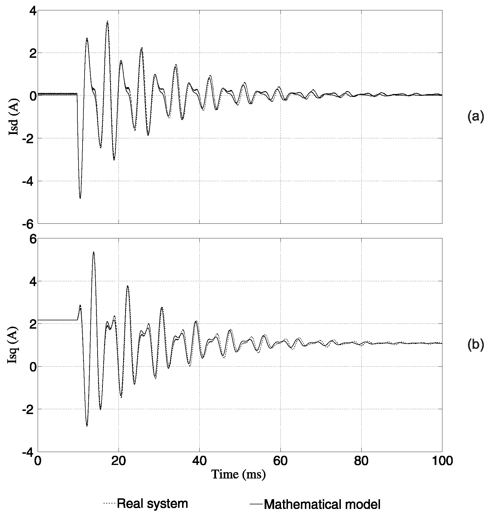
3. Dual Hybrid Power Filter Mathematical Model for Reactive Power Control

The strategy of the reactive power control is based on the instantaneous reactive power theory proposed by Akagi et al. [30]. The reactive power can be written in the rotating dq reference frame according to
Q = v P C C q i ¯ S d v P C C d i ¯ S q
where v P C C d and v P C C q are the dq-axis PCC voltages, i ¯ S d and i ¯ S q are the dq-axis grid currents. The signal of Equation (8) is changed in relation to that proposed in [30] for better coupling between the instantaneous and conventional power theories. Thus, the positive reactive power is related to inductive loads and negative reactive power is related to capacitive loads. In this paper, the voltage v P C C d is in phase with the grid voltage, i.e., v P C C q = 0 . Thus, it is observed that the reactive power control can be performed by controlling i ¯ S q .
The HPF modeling is developed from the equivalent circuit for reactive power control shown in Figure 2:
i F t o p A B C = i L A B C i S A B C
v F A B C = v S A B C + R t o p i t o p A B C + L t o p d i t o p A B C d t + 1 C t o p i F t o p A B C d t R S i S A B C L S d i S A B C d t .
Using Equation (9) in Equation (10) yields
v F A B C = v S A B C + P L ( t ) + P S ( t ) .
The terms P L ( t ) and P S ( t ) are written as follows:
P L ( t ) = R t o p i L A B C + L t o p d i L A B C d t + 1 C t o p i L A B C d t
P S ( t ) = R e q i S A B C L e q d i S A B C d t 1 C t o p i S A B C d t
where R e q = R S + R t o p and L e q = L S + L t o p .
To simplify the abc reference frame to the α β reference frame transformations, all terms in Equation (11) are derived so that the terms with integrals are eliminated. Since Clarke’s inverse transformation matrix is composed of constant elements in relation to time [31], the derivative of this matrix is null. Therefore, Equation (11) is rewritten as
d v F α β d t = d v S α β d t + P L α β ( t ) + P S α β ( t )
where the terms P L α β ( t ) and P S α β ( t ) are given by
P L α β ( t ) = T α β d P L ( t ) d t = R t o p d i L α β d t + L t o p d 2 i L α β d t 2 + 1 C t o p i L α β
P S α β ( t ) = T α β d P S ( t ) d t = R e q d i S α β d t L e q d 2 i S α β d t 2 1 C t o p i S α β .
As the control is performed in the dq rotating reference frame, the dq voltages and currents are obtained from Park’s transformation [32]:
f d q ( t ) = e j θ f α β ( t )
where f ( t ) can assume any three-phase voltage or current as a function of time.
Using Equation (17) in Equation (14):
d e j θ v F d q d t = d e j θ v S d q d t + P L d q ( t ) + P S d q ( t )
where P L d q ( t ) and P S d q ( t ) are given by
P L d q ( t ) = R t o p d e j θ i L d q d t + L t o p d 2 e j θ i L d q d t 2 + 1 C t o p e j θ i L d q
P S d q ( t ) = R e q d e j θ i S d q d t L e q d 2 e j θ i S d q d t 2 1 C t o p e j θ i S d q .
Using the derivatives d e j θ f ( t ) d t and d 2 e j θ f ( t ) d t 2 in Equation (18) and eliminating the term e j θ from this equation, the terms of the voltages and currents in the frequency domain (s) are
j ω V F d q + s V F d q = j ω V S d q + s V S d q + P L d q ( s ) + P S d q ( s )
where P L d q ( s ) and P S d q ( s ) are given by
P L d q ( s ) = R t o p j ω I L d q + s I L d q + 1 C t o p I L d q + L t o p ω 2 I L d q + j 2 ω s I L d q + s 2 I L d q
P S d q ( s ) = R e q j ω I S d q + s I S d q 1 C t o p I S d q L e q ω 2 I S d q + j 2 ω s I S d q + s 2 i S d q .
The model obtained in Equation (21) is compared to the complete system (Figure 1) through simulations performed in MATLAB/Simulink. For the simulations, all non-linear loads in the system have been disconnected making the load current ( I L ) and P L d q ( s ) null. The grid voltage V S and inverter output voltage V F are in phase with the d-axis, guaranteeing that the q-axis voltage components are null. In this paper, V S d is a not null constant and V F d is constant. However, the reference value of V F d can change for the reactive power control.
The currents of the model obtained in Equation (21) and the real system currents during the transient period are seen in Figure 3. This transient period occurs due to a step in V F d . The currents I S d and I S q obtained from the mathematical model and the real system are similar and both stabilize and converge to the same reference. Therefore, it can be stated that the mathematical model is consistent with the real system dynamics.
In Figure 3, it is observed that the current I S q changes with the step in V F d . Therefore, it is possible to control the current I S q through the voltage V F d . Consequently, the reactive power control can be realized by controlling the current I S q . The transfer function of the plant obtained in Equation (21) is given by
G ( s ) = I S q V F d = ω L e q s 2 + R e q L e q s + 1 C t o p L e q ω 2 L e q = K R ( s ) .

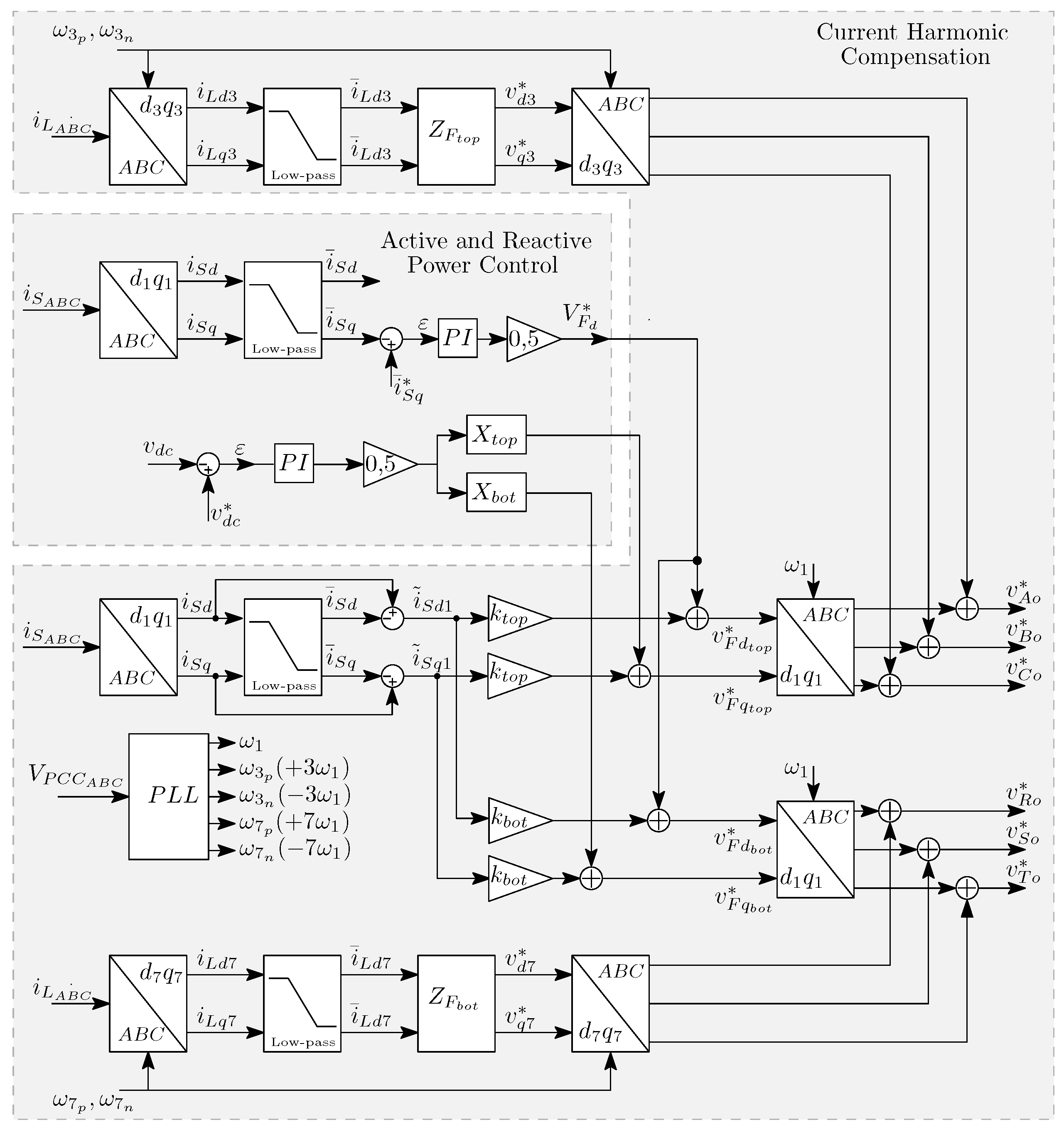
4. Hybrid Power Filter Control System

The control system for the HPF based on the NSI to compensate the harmonic components of currents and the reactive power consumed by the loads is shown in Figure 4. This control is divided in two subsystems: The first subsystem is responsible for the fundamental components control (dc-link voltage control fixed in a reference value and reactive power control). The second subsystem is responsible for the harmonic components control [9].

4.1. Active and Reactive Power Control

4.1.1. Reactive Power Control

A closed loop analysis is performed by utilizing a Proportional-Integral (PI) controller with unitary feedback, and the transfer function of the controller is given by
C ( s ) = k p Q s + k i Q s = Z ( s ) L ( s )
where k p Q and k i Q are the proportional and integral gains of the PI controller, respectively. Thus, the closed-loop transfer function can be obtained as follows:
I S q I S q * = C ( s ) G ( s ) 1 + C ( s ) G ( s ) = K Z ( s ) L ( s ) R ( s ) + K Z ( s ) = B ( s ) Q ( s )
where I S q * is the reference value of I S q in the frequency domain. k p Q and k i Q gains is designed using the polynomial roots Q(s) of the closed-loop transfer function expressed by Equation (26), which is given by
Q ( s ) = s 3 + R e q L e q s 2 + 1 C t o p L e q ω 2 ω k p Q L e q s ω k i Q L e q .
The polynomial in Equation (27) has three roots due to the two poles of the plant in Equation (24) and one pole of the controller in Equation (25). The criterion for the determination of the gains is the pole placement design [33], the same as performed in [34]. Therefore, the required polynomial A(s) has two complex conjugated poles (with a T and ω d being the real and imaginary parts, respectively), two complex poles, and one real pole. The polynomial A(s) required by the closed-loop system is given by
A ( s ) = ( s + ( a T + j ω d ) ) ( s + ( a T j ω d ) ) ( s + a )
where T is the relation between the position of the real part of the complex conjugated poles and the real pole.
Using the polynomial coefficients in Equations (27) and (28), the following relations are obtained:
T = 1 2 R e q a . L e q 1
k p Q = 1 ω 1 C t o p L e q w 2 + a 2 T 2 + ω d 2 + 2 a 2 T
k i Q = L e q ω ( a 3 T 2 + a . ω d 2 ) .
The variable T is defined from the relation obtained in Equation (29). The gains k p Q and k i Q are calculated based on Equations (30) and (31).
The position of the real pole is defined from the stabilization time of the plant at 2%, which is given by
t 2 % = 4 a .

4.1.2. Dc-Link Voltage Control

The top unit is responsible for controlling the dc-link voltage in a desirable value. The control strategy is the same as that used in [27], where the dc-link voltage control is based on the assumption that the power on the dc side is the same as the active power on the ac side of the converter. Therefore, if the dc-link voltage remains constant, the average value of the current that passes through the dc capacitor must be null. The resulting model for dc-link voltage control is based on an ideal capacitor and the closed-loop transfer function is given by
G C L ( s ) = V d c V d c * = k c v C k p s + k i s 2 + k p k c v C s + k i k c v C .
The controller is a conventional PI to cancel the error between the desired reference voltage V d c * and the measured dc-link voltage V d c .

4.2. Current Harmonic Compensation

4.2.1. Feedback Control

In this control, the grid harmonic currents components ( i ˜ S d and i ˜ S q ) are the current references of the proportional feedback control, as proposed in [9]. Thus, each extracted current harmonic is multiplied by a proportional gain (K), so that the reference voltages can be written as follows:
v F d q * = K i ˜ S d q
where v F d q * are the reference voltages produced by the feedback control.

4.2.2. Top and Bottom Feedforward Controls

The feedforward action is inserted into the control system for the improvement in harmonic current compensation. In the top unit, the feedforward control compensates the third harmonic of the load currents. The feedforward action of this unit has the function of creating a low impedance path for the third harmonic, preventing this harmonic from circulating through the grid. The reference voltages of the feedforward control to compensate the third harmonic are obtained as proposed in [9]:
v d q 3 * = R F t o p + j ω 3 L F t o p 1 ω 3 C F t o p i ˜ L d q 3
where X t o p = ω 3 L F t o p 1 ω 3 C F t o p .
In the bottom unit, the feedforward control compensates the seventh harmonic of the load currents. The feedforward action of this unit has the function of creating a low impedance path for the seventh harmonic, preventing this harmonic from circulating through the grid. The reference voltages of the feedforward control to compensate the seventh harmonic are obtained as
v d q 7 * = R F b o t + j ω 7 L F b o t 1 ω 7 C F b o t i ˜ L d q 7
where X b o t = ω 7 L F b o t 1 ω 7 C F b o t .
The reference voltages of the reactive power, dc-link voltage, feedback, and feedforward (third harmonic) controls are added for composing the reference voltages of the top unit. The reference voltages of the reactive power and feedforward (seventh harmonic) controls are added for composing the reference voltages of the bottom unit.

5. Experimental Prototype

A DHPF-NSI prototype was built using an insulated-gate bipolar transistor (IGBT) with a switching frequency of 20 kHz [35,36]. The general diagram of the experimental setup is shown in Figure 5. The hardware platform used to control the Dual Hybrid Power Filter inverter is a dSPACE development modular system based on a DS1005 processor board [37] and several boards for each special hardware task, i.e., a DS5101 board for Pulse-Width Modulation (PWM) generation [38], a DS2004 board for Analog/Digital (A/D) conversion [39], and a DS4002 board for Digital Input/Output (I/O) [40]. All boards are hosted in a dSpace PX10 expansion box that uses the DS817 board for bidirectional communication with a Personal Computer (PC) through optical fibers. The signals measured from the system are the grid currents i S A B C , load currents i L A B C , filter currents i F A B C , and line-to-line voltages v S A B C . A general view of the experimental test bench is shown in Figure 6. The prototype parameters can be seen in Table 2. The top unit LC filter is tuned to 300 Hz to mitigate the 5th harmonic and to contribute to low order current harmonics compensation. The bottom unit LC filter is tuned to 660 Hz to mitigate the 11th harmonic and to contribute to high-order current harmonics compensation.

5.1. Reactive Power Compensation Performance

Based on the parameters of the system presented in Table 2, the gains of the reactive power controller were calculated. The value of ω d defined for the design is 1820 rad/s, which is the same as in Equation (24). For controller design, the stabilization time ( t 2 % ) is equal to 150 ms. Based on Equation (32), the position of the real pole is obtained as 26.67 rad/s. The value of the variable T, calculated in Equation (29), is 1.64 s. Therefore, by substituting the values of the system parameters and the values of a, T, and ω d in Equations (30) and (31), the values of the controller gains were obtained. The controller gains are given in Table 3.
In order to verify the stability of the reactive power control system, the frequency response of the plant, G ( s ) in Equation (24), the controller, C ( s ) in Equation (25), and the open-loop transfer function, C ( s ) G ( s ) , are shown in Figure 7, using the data in Table 2 and Table 3. As can be seen, the designed controller has an infinite gain for dc (0 Hz) components, ensuring zero steady-state error in the reactive power control, and imposes a phase margin (PM) around 90 for the open-loop transfer function, which denotes a stable system. The cut-off frequency, 4.2 Hz at 0 dB, is sufficient to produce a step response with a settling time around 147 ms, very close to 150 ms, which is the value used for the controller design.
In order to validate the reactive control design, a step in i S q * was applied in the experimental prototype, producing the responses shown in Figure 8. Initially, the i S q * value was set to 3 A. At 25 ms, the value of i S q * was changed to 6 A, taking around 150 ms to i S q to reach the reference value, as can be seen in Figure 8a. The corresponding reactive power generated by the DHPF-NSI is shown in Figure 8b. It should be noted that the DHPF-NSI can compensate the reactive power consumed by any type of load in the range of 500–1050 var.

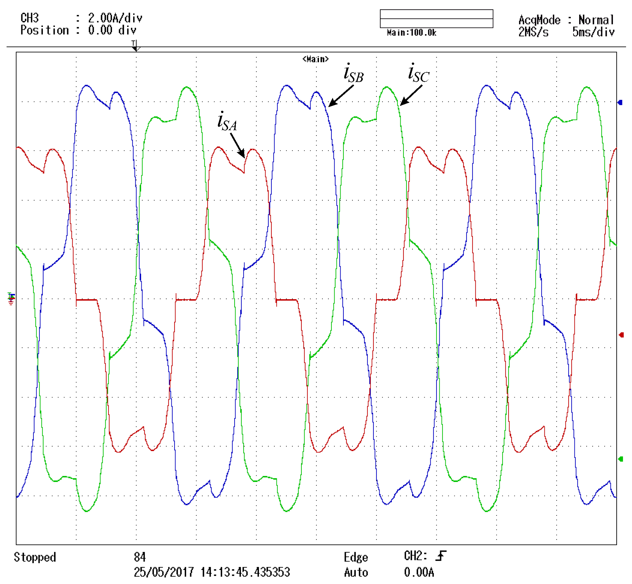
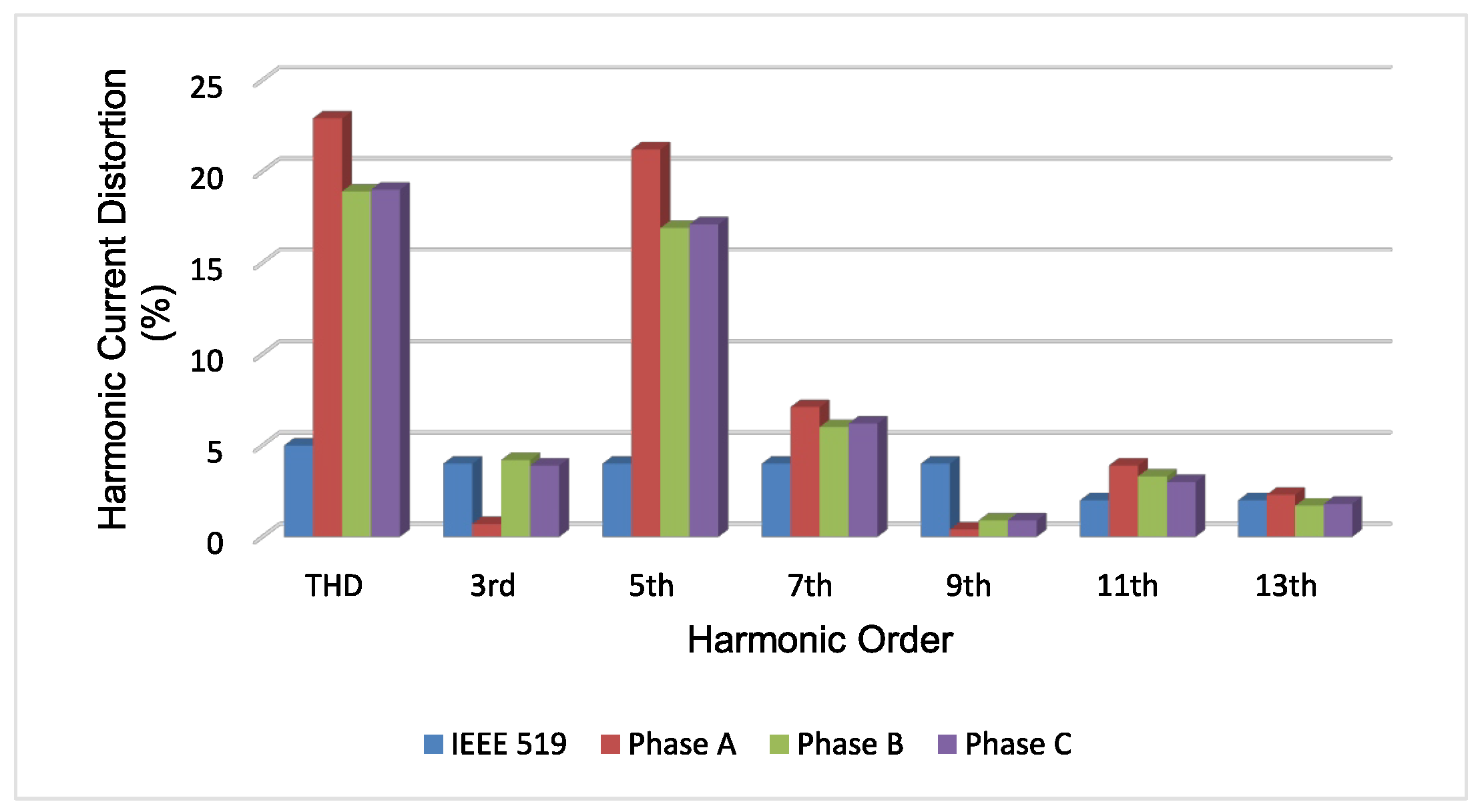
5.2. Current Harmonic Compensation Performance

The results in this section have been obtained using YOKOGAWA DL850 ScopeCorder [41] with a High-Speed 100 M/s, 12-Bit Isolation Module 720211 [42] and a power quality analyzer Fluke 434 series II [43] to measure the total harmonic distortion and the percentage value of each current harmonic. The IEEE 519-1992 standard [29] recommends that any load connected to general distribution system (up to 69 kV, which is the majority of industries) could consume currents with the harmonic limits defined by Table 4, which is a reproduction of Table 10.3 of [29]. The worst-case scenario would be the first line of Table 4, where each odd current harmonic up to the 9th order has a maximum distortion limit of 4%. From the 11th to the 15th order, the maximum distortion limit falls to 2%, and the THD (Total Harmonic Distortion, with the load at nominal power condition) is limited to 5%. All values are percentages of the fundamental component of the load current at nominal power condition.
With the DHPF-NSI is disabled, the currents waveforms and the THDs for the three-phase grid currents are shown in Figure 9 and Figure 10. The load currents present high harmonic values that are well above the limits recommended in Table 4 [29]. Based on Table 4 and Figure 9, it is possible to build the current harmonic profile of the grid currents with the DHPF-NSI disabled, which is shown in Figure 11.
As can be seen, not only are the 3rd, 5th, 7th, 11th, and 13th harmonic components of the grid currents above the IEEE 519-1992, but also the THDs of all three phases are as well. On the other hand, when the DHPF-NSI is enabled, the THDs and the waveforms of the grid currents are considerably improved, as shown in Figure 12 and Figure 13. For example, the THDs are reduced from 18.9–22.9% (Figure 9) to less than 5% (Figure 12) in all phases, respecting the THD limit recommended in Table 4 [29]. Based on Table 4 and Figure 12, it is possible to build the current harmonic profile of the grid currents with the DHPF-NSI enabled, which is shown in Figure 14. It is possible to see that the influences from the 5th to the 13th harmonic components are strongly reduced, below the limits of the IEEE 519-1992. For instance, the 5th harmonic component has a reduction from 16.9–21.2% (Figure 9) to less than 4% (Figure 12) in all phases, proving the effectiveness of the proposed DHPF-NSI. The current waveform results (grid, load, and filters) for Phase A are shown in Figure 15 in order to illustrate the individual performance of each hybrid filter in the load current harmonic compensation.

6. Conclusions

In this paper, two extra features have been proposed for the dual HPF based on the NSI: the compensation of triplen current harmonics and the reactive power support. Dual HPF are used because dual filters have a better compensation capacity than single filters, and this is needed to compensate triplen current harmonics. HPFs have a lower installed power when compared with APFs. The limits of reactive power that the DHPF-NSI can compensate as well as its mathematical model and the controller design for reactive power compensation have also been demonstrated. Experiments testing for the overall response of the proposed system, among other parameters, have been carried out, proving its feasibility in terms of reactive power support and harmonic compensation.

Author Contributions

Conceptualization, L.R.L.; Formal analysis, F.B. and C.H.d.O.L.; Funding acquisition, M.C.C.; Investigation, L.R.L.; Supervision, F.B.; Validation, C.H.d.O.L. and M.C.C.; Writing – original draft, C.H.d.O.L. and M.C.C.; Writing – review & editing, L.R.L. and F.B.

Acknowledgments

This work was partially supported by CAPES, CNPq Grant No. 305901/2015-0, No. 306106/2015-9 and No. 309789/2017-6 and FACEPE Grant No. APQ-0777-3.04/14, No. APQ-0896-3.04/14 and No. IBPG-1262-3.04/16.

Conflicts of Interest

The authors declare no conflict of interest.

References

  1. Jewell, W. Electrical power systems quality. IEEE Power Energy Mag. 2003, 99, 63–64. [Google Scholar] [CrossRef]
  2. Hingorani, N.G.; Gyugyi, L. Understanding FACTS Concepts and Technology of Flexible AC Transmission Systems; IEEE Press: Piscataway, NJ, USA, 2000; pp. 1–429. [Google Scholar]
  3. Conseil International des Grands Reseaux Electriques (CIGRE). Custom Power-State of the Art; CIGRE WG14.31; CIGRE: Paris, France, 2002; pp. 1–104. [Google Scholar]
  4. Institute of Electrical and Electronics Engineers (IEEE). IEEE Guide for Application of Power Electronics for Power Quality Improvement on Distribution Systems Rated 1 kV Through 38 kV; IEEE Standard 1409-2012; IEEE: New York, NY, USA, 2012; pp. 1–90. [Google Scholar]
  5. Hossain, E.; Tür, M.R.; Padmanaban, S.; Ay, S.; Khan, I. Analysis and Mitigation of Power Quality Issues in Distributed Generation Systems Using Custom Power Devices. IEEE Access 2018, 6, 16816–16833. [Google Scholar] [CrossRef]
  6. Rivas, D.; Moran, L.; Dixon, J.; Espinoza, J. Improving passive filter compensation performance with active techniques. IEEE Trans. Ind. Electron. 2003, 50, 161–170. [Google Scholar] [CrossRef]
  7. Fujita, H.; Akagi, H. A practical approach to harmonic compensation in power systems - series connection of passive and active filters. IEEE Trans. Ind. Appl. 1991, 27, 1020–1025. [Google Scholar] [CrossRef] [Green Version]
  8. Chen, L.; Jouanne, A. A comparison and assessment of hybrid filter topologies and control algorithms. In Proceedings of the IEEE 32nd Annual Power Electronics Specialists Conference, Vancouver, BC, Canada, 17–21 June 2001; pp. 565–570. [Google Scholar]
  9. Srianthumrong, S.; Akagi, H. A medium-voltage transformerless AC/DC power conversion system consisting of a diode rectifier and a shunt hybrid filter. IEEE Trans. Ind. Appl. 2003, 39, 874–882. [Google Scholar] [CrossRef]
  10. Limongi, L.R.; Roiu, D.; Bojoi, R.; Tenconi, A. Analysis of active power filters operating with unbalanced loads. In Proceedings of the IEEE Energy Conversion Congress and Exposition, San Jose, CA, USA, 20–24 September 2009; pp. 584–591. [Google Scholar]
  11. Ribeiro, R.L.A.; Azevedo, C.C.; Sousa, R.M. A robust adaptive control strategy of active power filters for power-factor correction, harmonic compensation, and balancing of nonlinear loads. IEEE Trans. Power Electron. 2012, 27, 718–730. [Google Scholar] [CrossRef]
  12. Furtado, P.C.S.; Rodrigues, M.C.B.P.; Braga, H.A.C.; Barbosa, P.G. Two-phase, three-wire shunt active power filter using the single-phase p-q theory. In Proceedings of the Brazilian Power Electronics Conference, Gramado, Brazil, 27–31 October 2013; pp. 1245–1250. [Google Scholar]
  13. Rahman, N.F.A.; Radzi, M.A.M.; Soh, A.C.; Mariun, N.; Rahim, N.A. Adaptive hybrid fuzzy-proportional plus crisp-integral current control algorithm for shunt active power filter operation. Energies 2016, 9, 737. [Google Scholar] [CrossRef]
  14. Monroy-Morales, J.L.; Campos-Gaona, D.; Hernández-Ángeles, M.; Peña-Alzola, R.; Guardado-Zavala, J.L. An active power filter based on a three-level inverter and 3D-SVPWM for selective harmonic and reactive compensation. Energies 2017, 10, 297. [Google Scholar] [CrossRef]
  15. Tan, K.-H.; Lin, F.-J.; Chen, J.-H. A three-phase four-leg inverter-based active power filter for unbalanced current compensation using a Petri probabilistic fuzzy neural network. Energies 2017, 10, 2005. [Google Scholar] [CrossRef]
  16. Hoon, Y.; Mohd Radzi, M.A.; Hassan, M.K.; Mailah, N.F. Control algorithms of shunt active power filter for harmonics mitigation: A review. Energies 2017, 10, 2038. [Google Scholar] [CrossRef]
  17. Peng, F.Z.; Akagi, H.; Nabae, A. A new approach to harmonic compensation in power systems—A combined system of shunt passive and series active filters. IEEE Trans. Ind. Appl. 1990, 26, 983–990. [Google Scholar] [CrossRef]
  18. Lam, C.S.; Wong, M.C. A novel b-shaped l-type transformerless hybrid active power filter in three-phase four-wire systems. In Proceedings of the 38th North American Power Symposium, Carbondale, IL, USA, 17–19 September 2006; pp. 235–241. [Google Scholar]
  19. Bhattacharya, A.; Chakraborty, C.; Bhattacharya, S. Parallel-connected shunt hybrid active power filters operating at different switching frequencies for improved performance. IEEE Trans. Ind. Electron. 2012, 59, 4007–4019. [Google Scholar] [CrossRef]
  20. Limongi, L.R.; Silva Filho, L.R.; Genu, L.G.B.; Bradaschia, F.; Cavalcanti, M.C. Transformerless hybrid power filter based on a six-switch two-leg inverter for improved harmonic compensation performance. IEEE Trans. Ind. Electron. 2015, 62, 40–51. [Google Scholar] [CrossRef]
  21. Luo, Z.; Su, M.; Yang, J.; Sun, Y.; Hou, X.; Guerrero, J.M. A repetitive control scheme aimed at compensating the 6k + 1 harmonics for a three-phase hybrid active filter. Energies 2016, 9, 787. [Google Scholar] [CrossRef]
  22. Tokiwa, A.; Yamada, H.; Tanaka, T.; Watanabe, M.; Shirai, M.; Teranishi, Y. New hybrid static VAR compensator with series active filter. Energies 2017, 10, 1617. [Google Scholar] [CrossRef]
  23. Corasaniti, V.F.; Barbieri, M.B.; Arnera, P.L. Hybrid active filter for reactive and harmonics compensation in a distribution network. IEEE Trans. Ind. Electron. 2009, 56, 670–677. [Google Scholar] [CrossRef]
  24. Salmeron, P.; Litran, S.P. A control strategy for hybrid power filter to compensate four-wires three-phase systems. IEEE Trans. Power Electron. 2010, 25, 1923–1931. [Google Scholar] [CrossRef]
  25. Asiminoaei, B.L.; Lascu, C.; Blaabjerg, F.; Boldea, I. Performance improvement of shunt active power filter with dual parallel topology. IEEE Trans. Power Electron. 2007, 22, 247–259. [Google Scholar] [CrossRef]
  26. Kim, G.-T.; Lipo, T.A. VSI-PWM rectifier/inverter system with a reduced switch count. IEEE Trans. Ind. Appl. 1996, 32, 1331–1337. [Google Scholar]
  27. Limongi, L.; Bradaschia, F.; Azevedo, G.M.S.; Genu, L.G.B.; Silva Filho, L.R. Dual hybrid power filter based on a nine-switch inverter. Electr. Power Syst. Res. 2014, 117, 154–162. [Google Scholar] [CrossRef]
  28. Liu, C.; Wu, B.; Zargari, N.R.; Xu, D.; Wang, J. A novel three-phase three-leg AC/AC converter using nine igbts. IEEE Trans. Power Electron. 2009, 24, 1151–1160. [Google Scholar]
  29. Institute of Electrical and Electronics Engineers (IEEE). IEEE Recommended Practices and Requirements for Harmonic Control in Electrical Power Systems; IEEE Standard 519-1992; IEEE: New York, NY, USA, 1993; pp. 1–112. [Google Scholar]
  30. Akagi, H.; Kanazawa, Y.; Nabae, A. Instantaneous Reactive Power Compensators Comprising Switching Devices without Energy Storage Components. IEEE Trans. Ind. Appl. 1984, IA-20, 625–630. [Google Scholar] [CrossRef]
  31. Duesterhoeft, W.C.; Schulz, M.W.; Clarke, E. Determination of Instantaneous Currents and Voltages by Means of Alpha, Beta, and Zero Components. Trans. Am. Inst. Electr. Eng. 1951, 70, 1248–1255. [Google Scholar] [CrossRef]
  32. Park, R.H. Two-reaction theory of synchronous machines generalized method of analysis-part I. Trans. Am. Inst. Electr. Eng. 1929, 48, 716–727. [Google Scholar] [CrossRef]
  33. Ioannou, P.A.; Sun, J.A. Robust Adaptive Control; PTR Prentice-Hall: Upper Saddle River, NJ, USA, 1996; pp. 803–813. ISBN 9780134391007. [Google Scholar]
  34. Ribeiro, R.L.A.; Rocha, T.O.A.; Sousa, R.M.; Santos, E.C.; Lima, A.M.N. A Robust DC-Link Voltage Control Strategy to Enhance the Performance of Shunt Active Power Filters Without Harmonic Detection Schemes. IEEE Trans. Ind. Electron. 2015, 62, 803–813. [Google Scholar] [CrossRef]
  35. Semikron IGBT Module SKM50GB12T4. Available online: https://www.semikron.com/dl/service-support/downloads/download/semikron-datasheet-skm50gb12t4-22892000/ (accessed on 25 May 2018).
  36. Semikron Gate Drive SKPC 22/2. Available online: http://astronix.biz/datasheets/SKPC22.PDF (accessed on 25 May 2018).
  37. Modular dSPACE System DS1005 Processor Board. Available online: https://www.dspace.com/shared/data/bkm/catalog2014_en/files/assets/basic-html/page332.html (accessed on 25 May 2018).
  38. dSPACE DS5101 Board PWM Generation. Available online: https://www.dspace.com/shared/data/pdf/2018/dSPACE_DS5101_Catalog2018.pdf (accessed on 25 May 2018).
  39. dSPACE DS2004 Board for A/D Conversion. Available online: https://www.dspace.com/shared/data/pdf/2018/dSPACE_DS2004_Catalog2018.pdf (accessed on 25 May 2018).
  40. dSPACE DS4002 Board for Digital I/O. Available online: https://www.dspace.com/shared/data/pdf/2018/dSPACE_DS4002_Catalog2018.pdf (accessed on 25 May 2018).
  41. YOKOGAWA DL850 ScopeCorder. Available online: https://cdn.tmi.yokogawa.com/BUDL850E-00EN.pdf (accessed on 25 May 2018).
  42. High-Speed 100 M/s, 12-Bit Isolation Module 720211. Available online: https://cdn.tmi.yokogawa.com/BUDL850E-01EN.pdf (accessed on 25 May 2018).
  43. Fluke 434-II Power Quality Analyzer. Available online: http://media.fluke.com/documents/F430-II_umeng0100.pdf (accessed on 25 May 2018).
Figure 1. Dual HPF based on the NSI (DHPF-NSI) connected to a three-phase electrical system.
Energies 11 01392 g001
Figure 2. Equivalent circuit for the fundamental ac voltage.
Energies 11 01392 g002
Figure 3. Dynamics of the model obtained in Equation (21) and the real system: (a) Current I S d ; (b) Current I S q .
Energies 11 01392 g003
Figure 4. Control diagram of the DHPF-NSI with fundamental and harmonic components control.
Energies 11 01392 g004
Figure 5. Single-line diagram of the experiment prototype showing the interface between the DHPF-NSI and dSPACE.
Energies 11 01392 g005
Figure 6. General view of the experimental test bench.
Energies 11 01392 g006
Figure 7. Frequency response of the plant, G ( s ) , the controller, C ( s ) , and the open-loop transfer function, C ( s ) G ( s ) , for the reactive power control.
Energies 11 01392 g007
Figure 8. Step responses for a change from 3 A to 6 A in i S q * at 25 ms: (a) current i S q injected by the DHPF-NSI; (b) reactive power generated by the DHPF-NSI.
Energies 11 01392 g008
Figure 9. Three-phase grid current harmonic components with the DHPF-NSI disabled.
Energies 11 01392 g009
Figure 10. Three-phase grid current waveforms with the DHPF-NSI disabled.
Energies 11 01392 g010
Figure 11. Three-phase grid current harmonic profile with the DHPF-NSI disabled.
Energies 11 01392 g011
Figure 12. Three-phase grid current harmonic components with the DHPF-NSI enabled.
Energies 11 01392 g012
Figure 13. Three-phase grid current waveforms with the DHPF-NSI enabled.
Energies 11 01392 g013
Figure 14. Three-phase grid current harmonic profile with the DHPF-NSI enabled.
Energies 11 01392 g014
Figure 15. Current waveforms for Phase A. From top to bottom: grid ( i S A ), load ( i L A ), top unit ( i F t o p A ) and bottom unit ( i F b o t A ).
Energies 11 01392 g015
Table 1. Possible switching states and the respective output voltages for leg AR of the NSI.
NSI Switching States S A S AR S R v Ao v Ro
1110 v d c 2 v d c 2
2011 v d c 2 v d c 2
3101 v d c 2 v d c 2
Table 2. Prototype parameters.
ParameterSymbolValue
Line-to-line grid voltage (rms) V ^ S 220 V
Grid frequency f R 60 Hz
Switching frequency f S 20 kHz
Dc-link voltage v d c 260 V
Dc-link capacitor C d c 4700 μ F
Top filter capacitor (5th harmonic) C F t o p 46 μ F
Top filter inductor (5th harmonic) L F t o p 6.12 mH
Top filter Resistor (5th harmonic) R F t o p 620 m Ω
Bottom filter capacitor (11th harmonic) C F b o t 46 μ F
Bottom filter inductor (11th harmonic) L F b o t 1.26 mH
Bottom filter resistor (11th harmonic) R F b o t 300 m Ω
Nonlinear three-phase load input inductor L a c 1 5 mH
Nonlinear three-phase load dc-link resistor R L 1 31 Ω
Unbalance load input inductor L a c 2 7 mH
Unbalance load inductor L L 2 128 mH
Unbalance load dc-link resistor R L 2 60 Ω
Linear three-phase load inductor L L 3 128 mH
Linear three-phase load dc-link resistor R L 3 24 Ω
Table 3. Gains of the reactive power controller for the prototype parameters.
ParameterSymbolValue
Real pole positiona26.67 rad/s
Variable TT1.64 s
Position of the imaginary part of the complex pole ω d 1820 rad/s
Proportional gain of reactive power control k p Q −0.075 Ω
Integral gain of reactive power control k i Q −1475.2 Ω · s 1
Table 4. Current Distortion Limits for General Distribution Systems (120 V Through 69 kV) [29].
Maximum Harmonic Current Distortion in Percent of I L
Individual Harmonic Order (Odd Harmonics)
I s c / I L <11 11 h < 17 17 h < 23 23 h < 35 35 h TDD
<20 *4.02.01.50.60.35.0
≥20 and <507.03.52.51.00.58.0
≥50 and <10010.04.54.01.50.712.0
≥100 and <100012.05.55.02.01.015.0
>100015.07.06.02.51.420.0
Even harmonics are limited to 25% of the odd harmonic limits above. Current distortions that result in a dc offset, e.g., half-wave converters, are not allowed. * All power generation equipment is limited to these values of current distortion, regardless of actual I s c / I L , where I s c = maximum short-circuit current at PCC, and I L = maximum demand load current (fundamental frequency component) at PCC.

