Experimental Investigation of the Loading Strategy of an Automotive Diesel Engine under Transient Operation Conditions

1
State Key Laboratory of Automotive Simulation and Control, Jilin University, Changchun 130025, China
2
Jilin Engineering Normal University, Innovative Research Team of Jilin Engineering Normal University (IRTJLENU), Changchun 130052, China
*
Author to whom correspondence should be addressed.
Energies 2018, 11(5), 1293; https://doi.org/10.3390/en11051293
Submission received: 13 March 2018
/
Revised: 4 May 2018
/
Accepted: 10 May 2018
/
Published: 18 May 2018
Abstract
:Targeting the performance optimization of an automotive diesel engine under transient operation conditions, in this research, the effect of several non-linear loading strategies on diesel performance have been experimentally analyzed using a heavy-duty turbocharged diesel engine running under transient conditions based on the constant 1650 r/min speed, the load is increased from 10% to 100% in a 5 s transition time The results show that the larger the early loading rate and change point load, the better the dynamic torque response. The peak values of smoke and CO and the transient average of brake specific fuel consumption (BSFC), soot and CO can be decreased by increasing the early loading rate by the loading strategies with the appropriate change point load during transient operation. However, combustion deteriorates under the loading process with an overlarge change point load, causing emissions to increase, and the larger the early loading rate, the worse the worsening. Based on the trade-off consisting of torque dynamic response, transient total and transient average of the BSFC and brake specific emissions, peak values of smoke and CO emissions, it is concluded that the loading strategy with the early loading rate is the 50% load per second and the change point load in the 25% load is the most suitable in these strategies.
1. Introduction
Turbocharged diesel engines are the prime movers for small and medium sized vehicles due to their reliability, widespread availability and excellent thermal efficiency. Their share in the highly competitive auto market keeps increasing, however, their transient operation is particularly important in daily operation conditions, especially in urban roads, where engine loads and speeds vary frequently and suddenly. In order to meet the increasingly stringent emission regulations and improve the popularity rate of diesel engines in the highly competitive automobile market, it is necessary to study their fuel economy and emission performance [1,2,3,4,5,6,7,8].
The transient operating conditions include the conditions with changing torque and changing speed (DSDT, DSIT, ISDT and ISID), constant speed and changing torque (CSIT and CSDT), constant torque and changing speed (CTDS and CTIS), starting and parking. In the European transient cycle (ETC), different driving conditions are represented: urban, rural and motorway driving. The duration of the entire cycle is 1800 s. The duration of each part is 600 s [9,10]. Consequently, during the process of development and calibration of the engine, the work cannot be completed if all the calibration parameters are verified as accurate based on the ETC, because the adjustment parameters are redundant and this would waste much time and money.
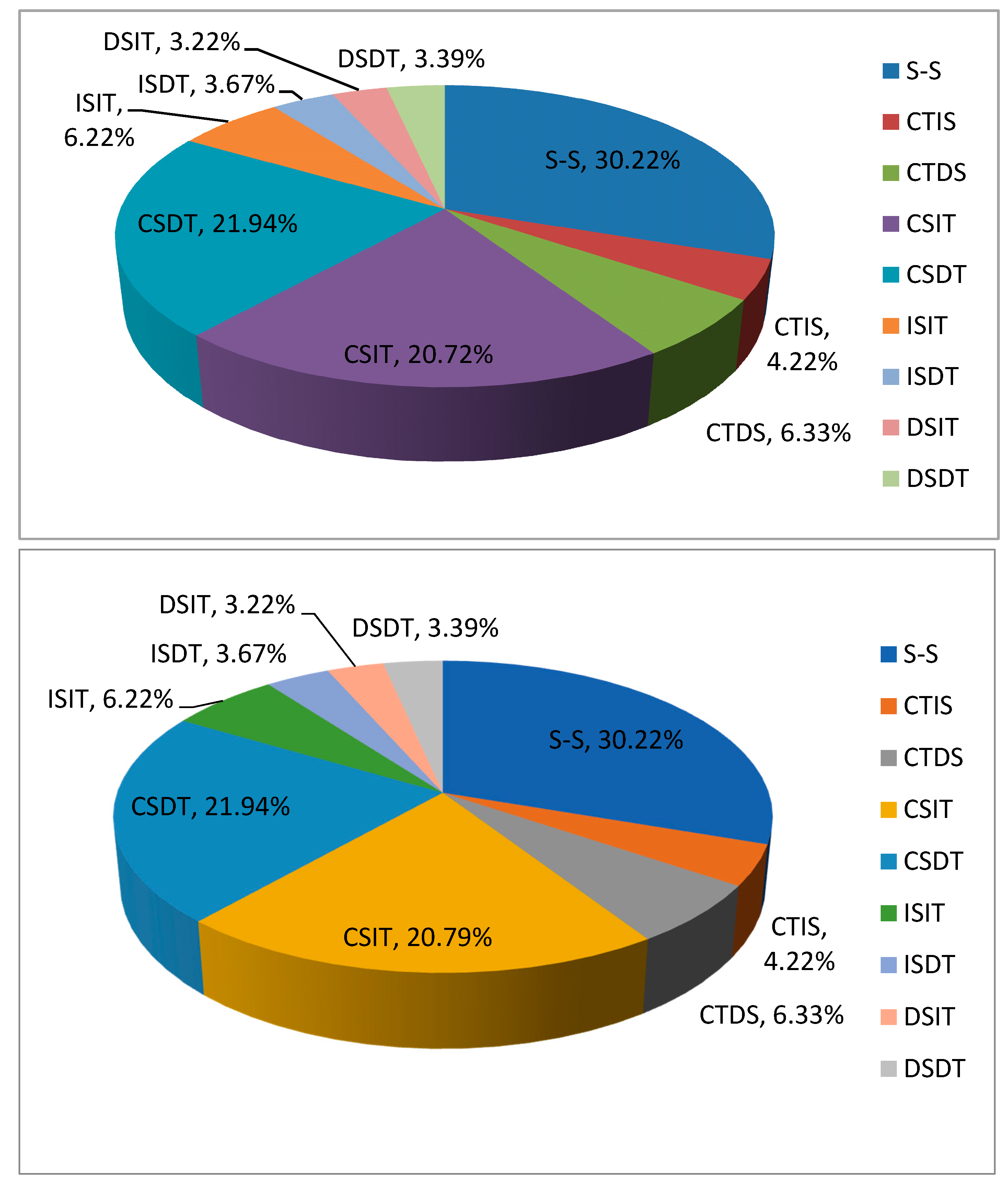
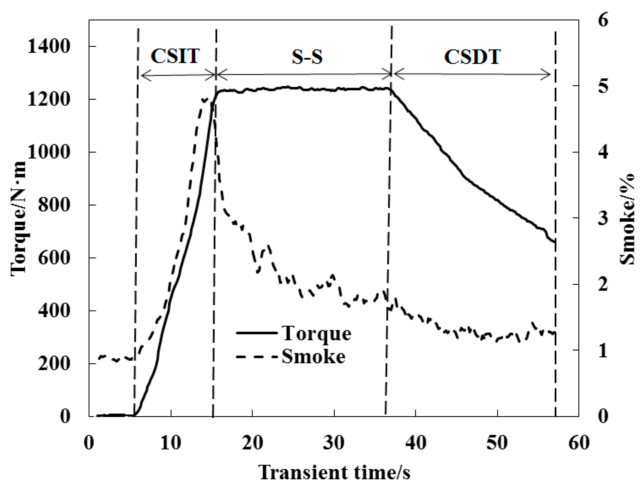
He [11] proposed assigning weights to a typical transient operation, except for starting and parking, by means of the transient characteristic of the entire ETC and some assumptions. The weight of a typical transient operation for the ETC is illustrated in Figure 1. It shows the heavy weights in the transient operation with constant speed and changing torque and steady-state condition (S-S) under the ETC, are 42.66% and 30.22%, respectively; however, the weight in transient operation with constant torque and changing speed (CTCS) is 10.55%. The transient operation under constant speed and changing torque (CSIT, CSDT) is the most popular, because its weight is 61.13% if the S-S is removed from the ETC. Moreover, the weight levels of CSIT and CSDT are almost the same. Furthermore, previous investigations have shown that engine performance (e.g., smoke emissions) degradation occurs at CSIT instead of CSDT, which is verified in Figure 2. Therefore, the transient conditions based on CSIT were studied experimentally in this paper.
A large number of studies have shown that during transient operation, especially in the CSIT condition, the clear deterioration in fuel consumption and smoke emissions relative to the S-S is a result of insufficient air supply caused by turbocharger lag, which degrades the combustion and the emissions [12]. Therefore, researchers have extensively studied the response rate of transient emission control and air supply.
For transient emission control, the optimal control strategy of EGR has been widely studied. David et al. [13] pointed out that the combination of EGR in high and low voltage circuits with fuel injection control strategy can reduce fuel consumption and emissions. Sui [14] proposed a transient emission control strategy based on exhaust gas emission limit and EGR valve opening feedback, which effectively improved the tradeoff between flue gas and NOx under transient conditions. However, the critical combustion process leading to the deterioration of emissions and fuel economy has not yet been fully studied. Precise investigation of combustion deterioration should lead to optimization of transient control strategies.
In addition, many control strategies have been developed to mitigate the delay in air supply caused by lagging of turbochargers. These include the proposal by IIya et al. [15] to use an auxiliary energy supply system for the turbocharger, the use of a high-pressure air spray assistant power supply (HPAS) by Han et al. [4] and the use of an two-stage turbocharging system by Serrano et al. [16] and Galindo et al. [2] In order to improve the emissions in the transient process, efforts should be made to increase the response rate of air supply. However, difficult gas control and immature control technology limit the optimization of transient performance and can’t improve fuel economy. Therefore, the direct gas supply strategy to improve the intake charging response in transient operation has become the bottleneck of development.
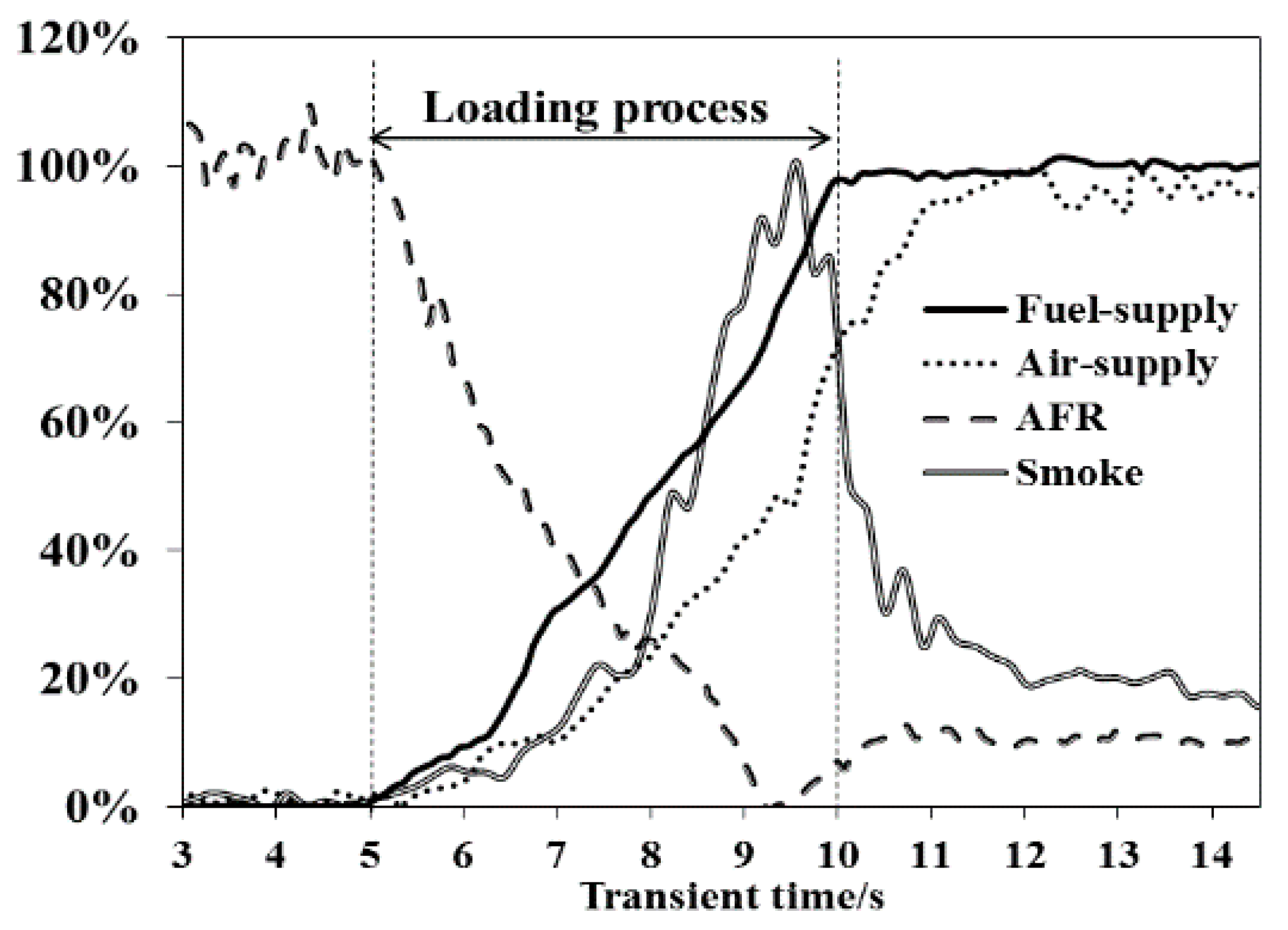
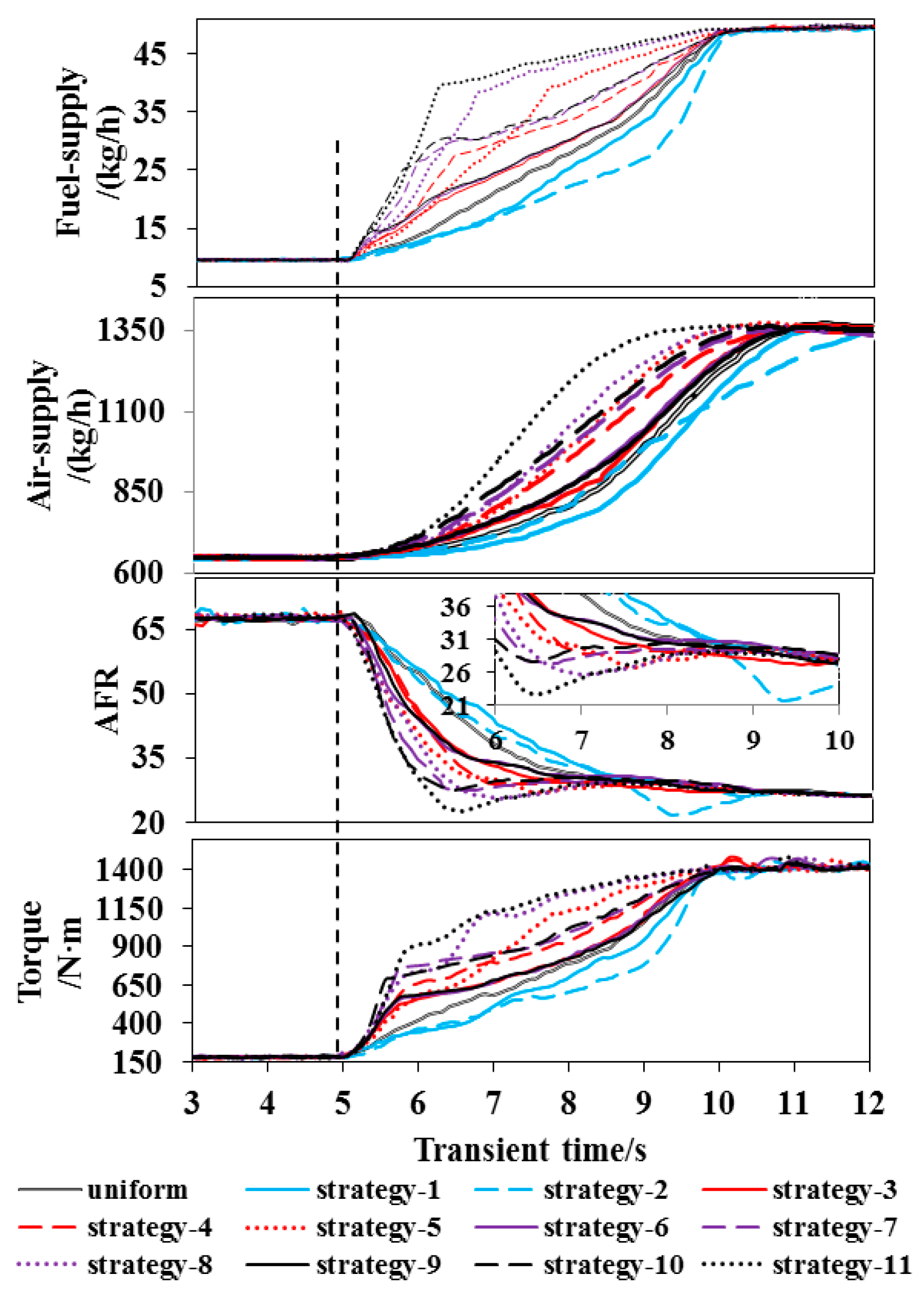
Figure 3 shows the response behavior of key performance parameters under the CSIT condition, in the early stage of uniform loading process. It illustrates that smoke increasing very slowly. Although the air-fuel ratio is reduced its absolute air fuel ratio is still larger. With the progress of the loading process, the air fuel ratio continues to decrease and the “valley point” appears. At this time, the smoke emission also peaks (the time of the two is almost identical), which indicates that the rapid decrease of the air fuel ratio in the late loading process is the main cause of the smoke deterioration.
Therefore, it uses the characteristics of large air-fuel ratio (AFR) in the early stage of the loading process (medium and small loads) and flexible adjustment of the fuel supply system to ensure that the fuel supply at the end of the transient is the same. Using a non-linear oil supply strategy, the oil supply rate in the early stage of the loading process is increased to reduce the oil supply rate at the later stage of the loading process, so that the air-fuel ratio at the later stage of the loading process is appropriately increased. Therefore it can ultimately achieve the goal of optimizing combustion and reducing smoke emissions. It increases the torque (constant 1650 r/min speed, increasing from 10% load to 100% load in 5 s) in constant speed, and tests and studies the change regular pattern of engine transient performance under different loading strategies.
In order to increase the contrast effect, eleven typical non-linear loading strategies were selected as the research objects. There are two “slow–fast” loading strategies and nine “fast–slow” loading strategies, and CPL are 25%, 50%, 75%, respectively. The experimental results are compared with eleven non-linear loading strategies. In CSIT, we find a strategy that is better than the linear loading strategy in the 11 nonlinear loading strategies. The better non-linear strategy can solve the problem of smoke deterioration. Other indicators is relatively good.
2. Measurement and Control Platform and Test Conditions
2.1. Measurement and Control Platform
For the complete ETC transient cycle test or study, it requires not only the power dynamometer with high response and reverse drag capacity, but also high response and high precision measurement and control equipment. However, the ETC can be simplified to a few important steady-state conditions and several typical transient conditions, such as CSIT, CSDT, CTIS and CTDS, which could be researched using an eddy current dynamometer, consequently greatly simplifying the research process of the ETC, reducing research costs and making the research more targeted toward optimization strategy.
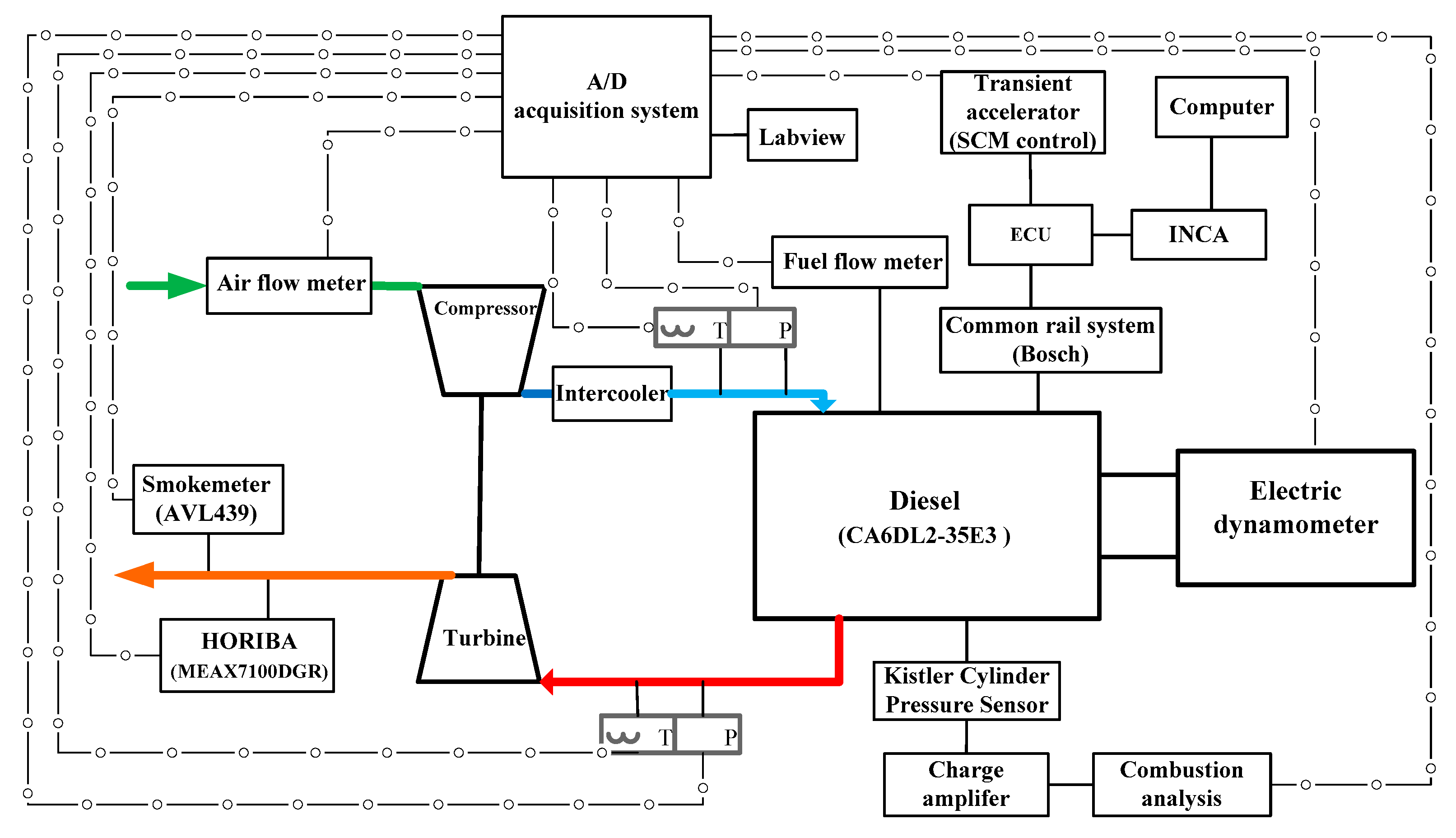
The schematic diagram of typical transient measurement and control platform is shown in Figure 4. The transient work is composed of CSIT, CSDT, CTDS and CTIS. The test platform adopts transient throttle voltage controller to precisely regulate the voltage signal of throttle valve. At the same time, the constant torque constant torque controlled eddy current dynamometer can realize the typical heavy hammer constant torque and constant torque transient conditions in the ETC transient test period. The high response rate sensor and high speed data acquisition card (millisecond precision) are used as the measuring system. The parameters such as engine speed, torque, intake quality, smoke, intake and exhaust are realized. Temperature and exhaust emissions. In addition, according to the orbit pressure and the duration of the injection instruction, the fuel injection is calculated by ECU, and the fuel flowmeter is corrected at the same time, thus improving the measurement accuracy and response rate. An experimental study on a turbocharged medium cooled diesel engine is carried out. The diesel engine is equipped with standard production hardware, including BOSCH ECU, Inca software, high pressure common rail injection system and turbocharger. The main technical features of the engine are shown in Table 1.
2.2. Test Conditions
The transient event is started by changing the accelerator pedal command (accelerator voltage) to ECU, the ECU regulates the desired torque output and the amount of fuel injected according to the accelerator instruction. In the experimental study, by adjusting a number of nonlinear load strategies, the load increased from 10% to 100% in a 5 s transition time by SCM at a constant speed of 1650 r/min.
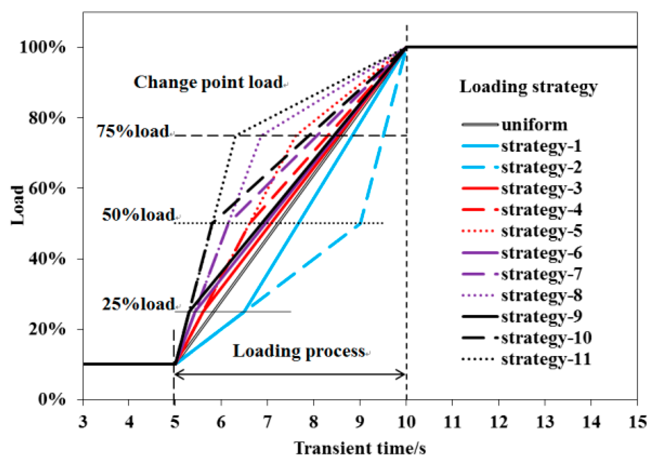
The non-linear loading strategies, including the “slow–fast” and “fast–slow” strategies, relative to the linear fuel-supply strategy, are shown in Figure 5 and Table 2. The so-called “slow–fast” loading strategy, the early loading rate (ELR), is less than the level of the linear fuel-supply strategy during the early loading process and the latter loading rate (LLR) is larger in the latter (e.g., Strategy 1 and Strategy 2 in Table 2 and Figure 5). However, the “fast–slow” loading strategy is in contrast with it (e.g., Strategies 3–11 in Table 2 and Figure 5). Besides, the 25% load, 50% load and 75% load are determined as CPL, which are the loads between the ELR and the LLR. The equation for the loading rate (γ) is Equation (1):
where γ is loading rate, is the initial load, is theterminal load, is the initial time and is the terminal time.
3. Results and Discussion
3.1. Influence of Non-Linear Loading Strategies on Dynamic Response of Torque
The response behaviors of fuel supply, air supply, AFR and torque under non-linear loading strategies are shown in Figure 6. It shows that the larger the CPL, the slower the response in the fuel supply, air supply and torque and that the AFR is reduced by the “slow–fast” loading strategies (e.g., Strategy 1 and Strategy 2). However, the response rate increase and AFR even appear to be the valley point during the later loading process. Thus, because of the quick LLR (e.g., Strategy 2, the LLR = 50% load/s) the turbocharger lag results in serious delay in the air supply relative to the fuel supply during the later loading process, causing the AFR to rapidly decrease, which is responsible for the degeneration of the combustion and smoke emissions by the “slow–fast” loading strategies.
However, the larger CPL and ELR, the more rapid the response in the fuel supply, air supply and torque are, and the AFR drops under the “fast–slow” loading strategies (e.g., Strategies 3–11). Besides, the AFR reaches a valley point during the early loading process under the “fast–slow” loading strategies with overlarge CPL (e.g., Strategy 11), which results in combustion degeneration and smoke emissions as well.
In order to conveniently and accurately evaluate the performance of the torque response under different non-linear loading strategies, in this paper, the increasing rate of response in a load is expressed by:
where is the increasing rate of torque response under a non-linear loading strategy, is the torque response time in a load under a non-linear loading strategy and is the torque response time in a load under a linear loading strategy. The torque response under the non-linear loading strategy is better than that under the linear loading strategy if the is a positive, and vice versa.
The torque response time and response increasing rate () in the 50% and 90% loads are presented in Figure 7. As shown, the increasing rate of torque response is negative under the “slow–fast” loading strategies (e.g., Strategies 1 and 2) and it reduces as the CPL increases, which indicates that the torque response worsens when compared to the linear strategy. However, the opposite behavior under the “fast–slow” strategies (e.g., Strategies 3–11) demonstrates that these strategies are beneficial for the torque response. As regards to these phenomena, because of the reduced fuel supply under the “slow–fast” loading strategy relative to the linear strategy during the whole loading process the response performance worsened, the reason being the opposite for the “fast–slow” strategies. Furthermore, the increasing rate in the 50% load is larger than for the 90% under the “fast–slow” strategies, their maximum levels are 25.3% and 14.7% in Strategy 11, respectively, while the increasing rate drops more rapidly in the 50% load than in the 90% under the “slow–fast” strategies, their minimum levels are −27.8% and −5.3% in Strategy 2, respectively.
3.2. Influence of Non-Linear Loading Strategies on Emission Performance of Diesel Engine
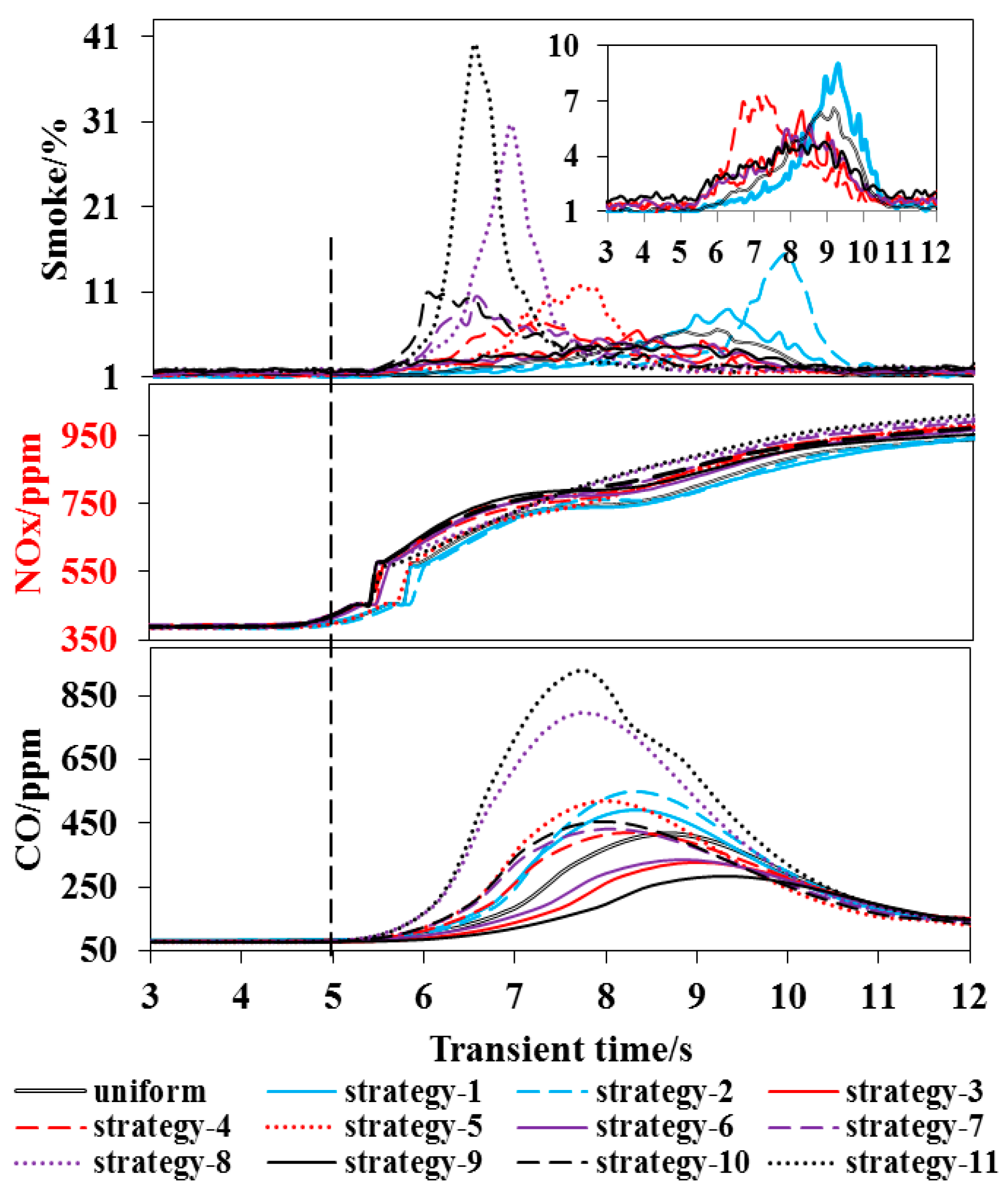
The response behavior and increasing rate (κ is defined Equation (3)) of smoke, NOx and CO emissions under the non-linear loading strategy are given in Figure 8 and Figure 9. As Figure 8 shows, the smoke and CO engine emissions under the “fast–slow” loading strategies with a 25% load CPL (e.g., Strategies 3, 6, and 9) are less than those for the linear loading strategy, and they reduce as the ELR increases while the NOx emissions show little fluctuation. For example, the smoke and CO peak values are 4.78% and 284 ppm and their increasing rates are −35.8% and −31.9% in Strategy 9, respectively, which demonstrates that the emissions performance is improved. Further, the excess air in the middle and low loads can be more fully utilized by suitably increasing the quantity of fuel injected during the early loading process under the “fast–slow” loading strategies with appropriate CPLs (e.g., Strategies 3, 6, and 9), which can improve turbocharger lag, increase the air supply and reduce the increasing rete of fuel supply during the later loading process, and is responsible for the combustion optimization and emission of CO and smoke. The rate of increase of emissions (κ) is described as Equation (3):
where κ is the increasingrate of emissions by a non-linear loading strategy, is the emissions by a non-linear loading strategy and the is the emissions by a linear loading strategy. The emission performance under the non-linear loading strategy is better than that under the linear loading strategy, if the κ is a negative, and vice versa.
However, the smoke and CO emissions deteriorated under the “fast–slow” loading strategies with overlarge CPLs (e.g., Strategies 4, 5, 7, 8, 10, and 11), and the emissions increase as the ELR and CPL increase. For example, the peak values of smoke and CO emissions are 40.1% and 926 ppm and the increasing rates are 449.3% and 122.5% in Strategy 11, respectively, which demonstrates that the emissions performance seriously deteriorates. Thus, the lower AFR results from the turbocharger lag and excessive fuel-injection quantity and the thermodynamics delay result from the thermal inertia of the cylinder wall-coolant system; As the amount of fuel increases during the loading process, the delay of gas supply becomes more serious, which leads to a sharp decline in fuel injection evaporation, atomization, air mixed fuel and combustion scale. It lead smoke and CO emissions to soar. (e.g., Strategy 11 shown in Figure 9).
Besides, the increasing rates of smoke and CO are also positive under “slow–fast” loading strategies (e.g., Strategies 1 and 2) and the heavier the CPL, the greater the smoke and CO peak values (the reason is given in the first paragraph under Section 3.1). Moreover, because of the difference in the formation mechanism between NOx and smoke [17,18,19,20,21] its increasing rates in different loading strategies are contrary to those of the smoke emission for NOx emission, but the levels of these increasing rates are small.
3.3. Influence of Non-Linear Loading Strategies on Comprehensive Transient Performance
Targeting the comprehensive evaluation of engine performance under transient operation with different loading strategies, the transient total and transient average are presented and dictated by Equations (4)–(6). The transient total is the integral value of the performance parameter during the total process of transient operation, and the transient average is the average brake specific value of the performance parameter:
where M is the transient total of a performance parameter (g), is a function for the variation of performance parameter as the transient time, is the initial time and is the terminal time during transient operation, W is the total work during the whole transient process (), is a function of power as the transient time, is the transient average of the some performance parameter
( ).
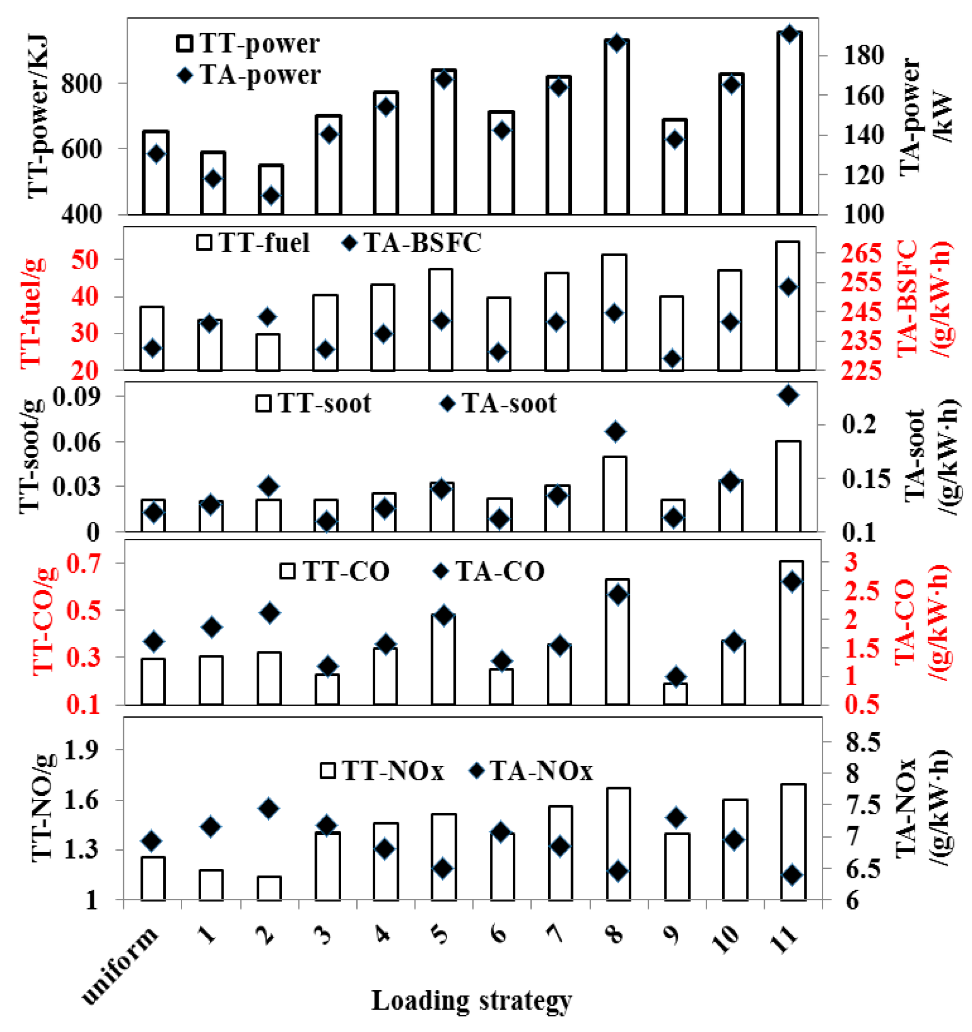
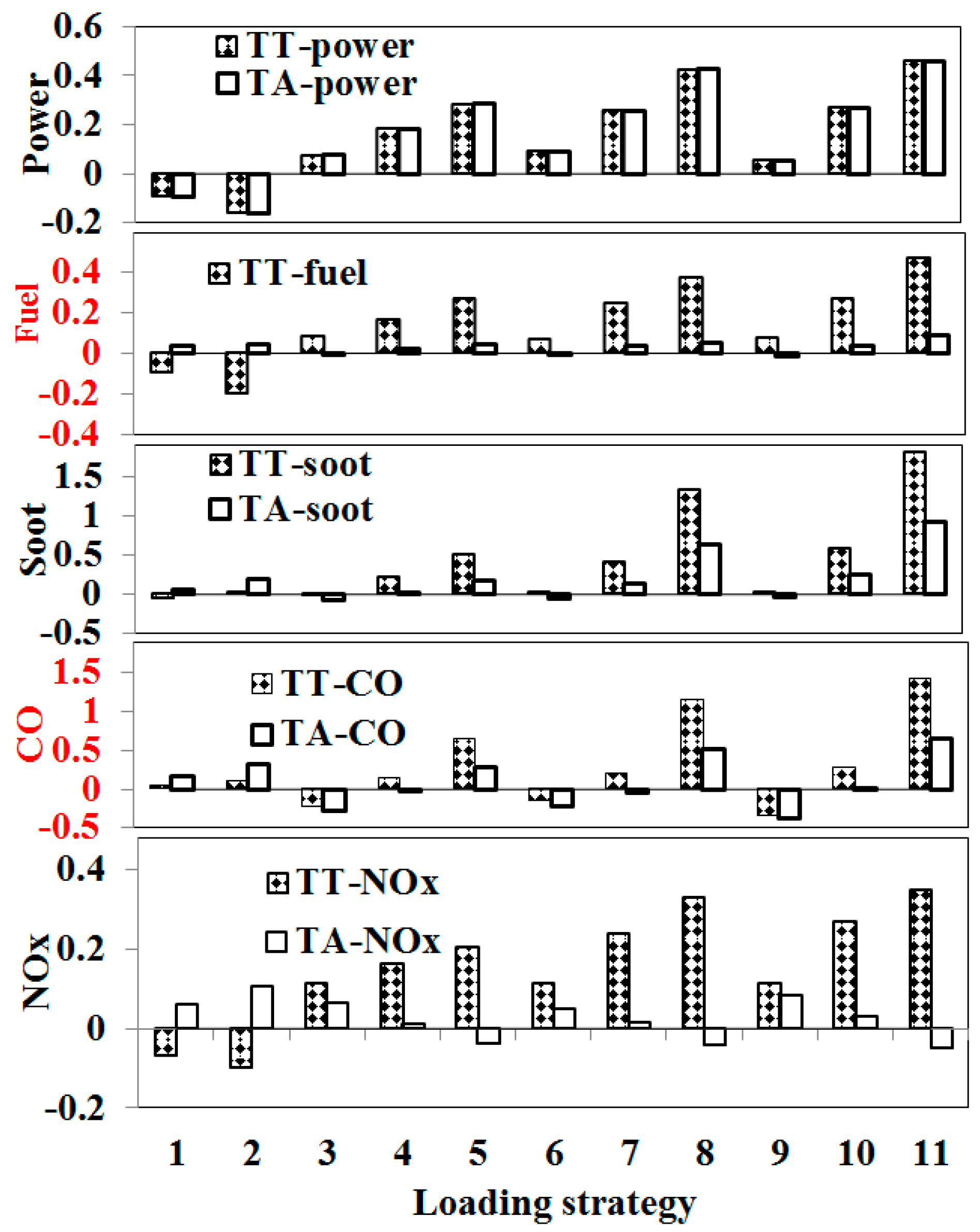
Figure 10 is the comparison of transient total and transient average value, which is the engine’s key performance parameters calculated according to Formulas (2) and (3) during loading. Figure 11 shows the increase rate of the engine main performance parameters relative to the linear strategy value under each loading strategy. As shown in Figure 10, when the first loading rate is less than the linear loading rate (strategy 1, 2), total power, average power, total fuel consumption and total NOx emissions decrease with the increase of “transition point load”, while the average specific fuel consumption, soot and CO total emission and soot, CO and NOx flat average emissions increase with the increase of “transition point load”.
The lower transient total of power and fuel consumption and the transient average of BSFC is a result of a small amount of fuel-injection quantity under the “slow–fast” loading strategy. However, the lower AFR results in combustion deterioration during the latter loading process, causing the transient average, consisting of BSFC and brake specific emissions, to gradual increase, their increasing rates of BSFC, soot, CO and NOx under Strategy 2 are 4.6%, 0.5%, 9.8% and 10.4%, respectively.
For the whole loading process, when the “first loading rate” was bigger than the linear loading rate (e.g., Strategy 3~11), the total power, total fuel consumption, total soot, total CO and NOx emissions and average power, mean fuel consumption, soot and CO mean emissions increased with the increase of “first loading rate” and “transition point load” (e.g., Strategy 5, 8, 11). This is because when the first loading rate is greater than the linear loading rate, the amount of fuel injection in the whole loading process is increased (e.g., “oil supply” in Figure 6). It increases the work capacity, the total fuel consumption, the average power and the total emission of the loading process and increases with the increase of the first loading rate and the transition point load. The performance parameters of “strategy 11” reached the maximum [22].
Besides, for the “fast–slow” loading strategies with 25% CPL (e.g., Strategies 3, 6, and 9), the increasing rates in the transient average of BSFC, soot and CO emissions are negative, which indicates that these performances are improved, and the optimal is Strategy 9 where the increasing rates are −1.5%, −4.7% and −38.0%, respectively. The excess air of the middle and low loads can be fully utilized by suitably increasing the fuel-injection quantity during the early loading process and reducing the increasing rate of fuel supply during the latter loading process, which can increase the air supply during the whole loading process and optimize the combustion process, and is responsible for the optimization of emissions performance and effective thermal efficiency. Moreover, the larger the ELR, the smaller the transient average levels in BSFC and soot and CO emissions under the “fast–slow” loading strategy [23].
However, for the “fast–slow” loading strategies with 50% and even bigger 50% CPL (e.g., Strategies 4, 5, 7, 8, 10, and 11), the average ratio of fuel consumption, soot and CO in transient process increased to different degrees, and the biggest increase of strategy 11 is 9%, 92.2% and 65.3%, respectively. This is because of the above loading strategies (strategy 4, 5, 7, 8, 10, 11). Due to the rapid oil supply rate in the early period and the long duration of high speed injection, the AFR in the early transient process decreases rapidly and causes the larger anoxic environment in the cylinder. At this time, the low thermal state in the cylinder is not conducive to the evaporation, atomization and mixing of oil and gas in the cylinder, it results in the deterioration of combustion, so the fuel consumption, smoke and CO emission increase (e.g., Strategy 11 shown in Figure 11).
For NOx emissions, the transient average decreases as the CPL and ELR increase, and the maximum increasing rate is 8.4% in Strategy 9, the minimum is 5.1% in Strategy 11 under the “fast–slow” loading strategies (e.g., Strategies 3–11 shown in Figure 11).
4. Discussion and Prospects
4.1. Discussion for Choosing the Better Loading Strategy
Based on the comparative analysis for torque response, transient total and transient average, several laws can be summarized as follows: when the smoke emission optimization is the main goal during the whole loading process, Strategy 9 is the best. The smoke emission peak value can be reduced by 34.3%; further, the levels of the BSFC and CO transient average are reduced by 1.5% and 38.0%, respectively, and the performance of the torque response is increased by 4.7% compared with the linear loading strategy. However, the NOx transient average and total fuel consumption are increased by 8.4% and 7.2%, respectively.
When saving total fuel consumption is the main goal during whole loading process, Strategy 2 is the best. The total fuel consumption can be reduced by 20.2% relative to the linear loading strategy; however, the torque response performance decreased by 5.8%, and the transient average levels in BSFC, soot, NOx and CO increased by 4.6%, 19.7%, 31.7% and 10.4%, respectively.
When the performance of torque response is the main optimization goal during the loading process, Strategy 11 is the best. It can be increased by 25.3%, and the NOx transient average decreased by 5.1% relative to the linear loading strategy; however, the other performances seriously deteriorate, including the total fuel consumption and the peak values of smoke and CO which increased by 46.7%, 449.3% and 122.5%, respectively. Furthermore, the BSFC, soot and CO transient average values increased by 9.0%, 92.2% and 65.3%, respectively.
When improving the trade-off among torque response, transient total and transient average is the main goal during the whole loading process, the “fast–slow” loading strategy with 25% CPL is beneficial in improving performance, including torque response, combustion and emissions. Strategy 9 is the best, its specific advantages are depicted in the second paragraph in Section 3.2.
4.2. Prospects
In this paper, eleven non-linear loading strategies were investigated to improve transient performance, and to obtain a better loading strategy; however, more intensive studies could be undertaken in the future. First, different “first loading rates” may have different “transition point load” and should be further verified. Second, the optimal loading strategy aimed at optimizing transient combustion and emission may be not only two stages of loading rate, but may be a curve with multiple segments or even multiple items.
5. Conclusions
The conclusions of this study are as follows: torque response performance can be improved by the “fast–slow” loading strategy and the larger the ELR and CPL, the better the torque response. Further, Strategy 11 is the best one, and could improve torque response performance by 25.3%. However, smoke emissions seriously deteriorate; its peak level increased by 449.3% relative to that under the linear loading strategy.
The peak values of CO and smoke emissions and the transient average of BSFC, soot and CO decrease as the ELR increases under the “fast–slow” loading strategy with the 25% CPL; however, combustion and emissions seriously deteriorate in the overlarge CPL.
The smaller the ELR and the CPL became, the lower the total fuel consumption during the whole loading process. Further, the maximum reduction in Strategy 2, is reduced by 20.2%. However, the BSFC and brake specific emissions are rapidly raised.
Based on the trade-off consisting of torque response, peak values of smoke and transient average in BSFC and brake specific emissions, Strategy 9 with 50%/s ELR and 25% CPL is the better loading strategy, which could improve torque response by 4.7% and drop the peak levels in smoke and CO and transient average of BSFC by 34.3%, 31.9% and 1.5%, respectively, compared with the linear loading strategy, while the total fuel consumption and NOx emissions increase slightly.
Through the experiment, it concludes experimental results are applicable to the studied engine and instructive for other diesel engine.
Author Contributions
Q.L., Z.L., J.T. and Y.H. conceived and designed the experiments; Q.L. and J.W. performed the experiments; Q.L. and J.F. analyzed the data; Q.L. wrote the paper. All authors read and approved the manuscript.
Funding
This research was funded by [the National Key R&D Program of China] grant number [2017YFB0103503], [the National Natural Science Foundation of China] grant number [51576089] and [2017 scientific research project of the Jilin Provincial Education Department] grant number [JJKH2017159KJ].
Acknowledgments
This work was supported by the National Key R&D Program of China (Grant No. 2017YFB0103503) and the National Natural Science Foundation of China (Grant No. 51576089). This work was also supported by program for innovative research team of Jilin Engineering Normal University (IRTJLENU) and 2017 scientific research project of the Jilin Provincial Education Department (JJKH2017159KJ).
Conflicts of Interest
All authors declare no conflict of interest.
Nomenclature
| ETC | European transient cycle |
| DSDT | decreasing speed and decreasing torque |
| DSIT | decreasing speed and increasing torque |
| ISDT | increasing speed and decreasing torque |
| ISIT | increasing speed and increasing torque |
| CSDT | constant speed and decreasing torque |
| CSIT | constant speed and increasing torque |
| CTDS | constant torque and decreasing speed |
| CTIS | constant torque and increasing speed |
| S-S | steady-state condition |
| EGR | exhaust gas recirculation |
| AFR | air-fuel ratio |
| ECU | electronic control unit |
| SCM | single chip micyoco |
| ELR | early loading rate |
| CPL | change point load |
| LLR | latter loading rate |
| TT | transient total |
| TA | transient average |
| CO | carbon monoxide |
| NOx | nitrogen oxides |
| BSFC | brake specific fuel consumption |
References
- Choi, S.; Myung, C.L.; Park, S. Review on characterization of nano-particle emissions and PM morphology from internal combustion engines. Int. J. Autom. Technol. 2014, 15, 219–227. [Google Scholar] [CrossRef]
- Galindo, J.; Gliment, H.; Guariola, C.; Doménech, J. Strategies for improving the mode transient in a sequential parallel turbocharged automotive diesel engine. Int. J. Autom. Technol. 2009, 10, 141–149. [Google Scholar] [CrossRef]
- Xia, M.; Zhao, C.L.; Zhang, F.J.; Huang, Y. Modeling the Performance of a New Speed Adjustable Compound Supercharging Diesel Engine Working under Plateau Conditions. Energies 2017, 10, 689. [Google Scholar] [CrossRef]
- Han, Y.Q.; Liu, Z.C.; Wang, Z.S.; Zhu, R.Q. HPAS control strategies and their effects on diesel engine under transient operations. Trans. CSICE 2006, 24, 513–517. [Google Scholar] [CrossRef]
- Sun, H.; Hanna, D.; Niessen, P.; Fulton, B.; Hu, L.; Curtis, E.W.; Yi, J. Experimental evaluation of advanced turbocharger performance on a light duty diesel engine. SAE Int. J. Engines 2013, 6, 788–796. [Google Scholar] [CrossRef]
- Lai, C.; Sun, W.; Li, G.; Tan, M.Z.; Chen, S.B.; Li, J.; Dou, H.L. Effect of BTL-diesel blended fuel on emitted particle size distribution in common-rail diesel engine under transient conditions. Chin. Intern. Combust. Engine Eng. 2012, 33, 45–51. [Google Scholar] [CrossRef]
- Payri, F.; Torregrosa, A.J.; Broatch, A.; Monelletta, L. Assessment of diesel combustion noise overall level in transient operation. Int. J. Autom. Technol. 2009, 10, 761–769. [Google Scholar] [CrossRef]
- Han, Y.Q.; Zhang, L.P.; Liu, Z.C.; Tian, J. Investigation of transient deterioration mechanism and improved method for turbocharged diesel engine. Energy 2016, 116, 250–264. [Google Scholar] [CrossRef]
- Myung, C.L.; Kim, J.; Kwon, S.; Choi, K.; Ko, A.; Park, S. Nano-particle emission characteristics of European and worldwide harmonized test cycles for heavy-duty diesel engines. Int. J. Autom. Technol. 2011, 12, 331–337. [Google Scholar] [CrossRef]
- Rakopoulos, C.D.; Dimaratos, A.M.; Giakoumis, E.G.; Rakopoulos, D.C. Evaluation of the effect of engine, load and turbocharger parameters on transient emissions of diesel engine. Energy Convers. Manag. 2009, 50, 2381–2393. [Google Scholar] [CrossRef]
- He, S.C. Simulation of Automobile Turbocharged Diesel Engine under Transient Operating Conditions. Master’s Thesis, Jilin University, Changchun, China, 2009. [Google Scholar]
- William, G.; David, H.; David, F.; Michael, A.; Roger, K. Analysis of deviations from steady state performance during transient operation of a light duty diesel engine. SAE Int. J. Engines 2012, 5, 909–922. [Google Scholar] [CrossRef]
- Heuwetter, D.; Glewen, W.; Meyer, C.; Foster, D.E.; Andrie, M.; Krieger, R. Effects of low pressure EGR on transient air system performance and emissions for low temperature diesel combustion. SAE Tech. Pap. 2011. [Google Scholar] [CrossRef]
- Sui, L.G. Simulation and Optimization of Turbo-Charged Diesel Engine Performance under Transient Operations. Ph.D. Thesis, Jilin University, Changchun, China, 2012. [Google Scholar]
- Kolmanovsky, I.; Stefanopoulou, A.G. Evaluation of turbocharger power assist system using optimal control techniques. SAE Trans. 2000, 109, 518–528. [Google Scholar] [CrossRef]
- Serrano, J.R.; Arnau, F.J.; Dolz, V.; Tiseira, A.; Lejeune, M.; Auffret, N. Analysis of the capabilities of a two-stage turbocharging system to fulfil the US207 anti-pollution directive for heavy duty diesel engines. Int. J. Autom. Technol. 2008, 9, 277–288. [Google Scholar] [CrossRef]
- Li, G.; Zhang, C.H.; Li, Y.Y. Effects of diesel injection parameters on the rapid combustion and emissions of an HD common-rail diesel engine fueled with diesel-methanol dual-fuel. Appl. Therm. Eng. 2016, 108, 1214–1225. [Google Scholar] [CrossRef]
- Zhou, J.X.; Zhou, S.; Zhu, Y.Q. Characterization of Particle and Gaseous Emissions from Marine Diesel Engines with Different Fuels and Impact of After-Treatment Technology. Energies 2017, 10, 1110. [Google Scholar] [CrossRef]
- Liu, Z.C.; Yu, K.B.; Tian, J.; Han, Y.Q.; Qi, S.L.; Teng, P.K. Influence of rail pressure on a two-stage turbocharged Heavy-duty diesel engine under transient operation. Int. J. Autom. Technol. 2017, 18, 19–29. [Google Scholar] [CrossRef]
- Agarwal, A.K.; Dhar, A.; Gupta, J.G.; Kim, W.I.; Choi, K.; Lee, C.S.; Park, S. Effect of fuel injection pressure and injection timing of Karanja biodiesel blends on fuel spray, engine performance, emissions and combustion characteristics. Energy Convers. Manag. 2015, 91, 302–314. [Google Scholar] [CrossRef]
- Liu, Z.C.; Yuan, X.; Tian, J.; Han, Y.; Li, R.; Gao, G. Investigation of sectional-stage loading strategies on a two-stage turbocharged heavy-duty diesel engine under transient operation with EGR. Energies 2018, 11, 69. [Google Scholar] [CrossRef]
- Zhang, J.; Shen, T.; Xu, G.; Kako, J. Wall-wetting model based method for air-fuel ratio transient condition in gasoline engine with dual injection system. Int. J. Autom. Technol. 2013, 14, 867–873. [Google Scholar] [CrossRef]
- Shen, Z.J.; Liu, Z.C.; Tian, J.; Liu, J.W. Investigation of in-cylinder gas stratification of diesel engine during intake and compression stroke. Energy 2014, 72, 671–679. [Google Scholar] [CrossRef]
Figure 1.
The weights of a typical transient operation for the ETC.

Figure 2.
Engine smoke emissions under constant speed (1650 r/min) changing the torque transient operating conditions.
Figure 2.
Engine smoke emissions under constant speed (1650 r/min) changing the torque transient operating conditions.

Figure 3.
The response behavior of key performance parameters under the CSIT condition.

Figure 4.
Schematic diagram of a typical transient measurement and control platform.

Figure 5.
Loading strategies based on a constant speed at 1650 rpm and increasing load from 10% to 100% over a 5-s transition time.
Figure 5.
Loading strategies based on a constant speed at 1650 rpm and increasing load from 10% to 100% over a 5-s transition time.

Figure 6.
Influence of non-linear loading strategies on dynamic response of significant parameters based on the constant speed of 1650 rpm, the load is increased from 10% to 100% in 5 s of transition time.
Figure 6.
Influence of non-linear loading strategies on dynamic response of significant parameters based on the constant speed of 1650 rpm, the load is increased from 10% to 100% in 5 s of transition time.

Figure 7.
Influence of non-linear loading strategies on the dynamic response of torque in 50% and 90% loads under a constant speed at 1650 rpm and increasing load from 10% to 100% over a 5-s transition time.
Figure 7.
Influence of non-linear loading strategies on the dynamic response of torque in 50% and 90% loads under a constant speed at 1650 rpm and increasing load from 10% to 100% over a 5-s transition time.

Figure 8.
Influence of non-linear loading strategies on emissions under constant speed at 1650 rpm and increasing load from 10% to 100% over a 5-s transition time.
Figure 8.
Influence of non-linear loading strategies on emissions under constant speed at 1650 rpm and increasing load from 10% to 100% over a 5-s transition time.

Figure 9.
The increasing rate of the peak values of emissions under non-linear loading strategies based on a constant speed at 1650 rpm and increasing load from 10% to 100% over a 5-s transition time.
Figure 9.
The increasing rate of the peak values of emissions under non-linear loading strategies based on a constant speed at 1650 rpm and increasing load from 10% to 100% over a 5-s transition time.

Figure 10.
Comparison of the transient total and transient average of the significant performance parameters under different loading strategies based on the constant speed of 1650 rpm, the load is increased from 10% to 100% in 5 s of transition time.
Figure 10.
Comparison of the transient total and transient average of the significant performance parameters under different loading strategies based on the constant speed of 1650 rpm, the load is increased from 10% to 100% in 5 s of transition time.

Figure 11.
Comparison of the increasing rate on the transient total and transient average of the significant performance parameters under non-linear loading strategies based on a constant speed of 1650 rpm and increasing load from 10% to 100% over a 5-s transition time.
Figure 11.
Comparison of the increasing rate on the transient total and transient average of the significant performance parameters under non-linear loading strategies based on a constant speed of 1650 rpm and increasing load from 10% to 100% over a 5-s transition time.


Table 1.
Test engine specifications.
| Item | Value |
|---|---|
| Type of Engine | Straight line six cylinder four value |
| Diameter (mm) × Stroke (mm) | 112 × 145 |
| Power Rating (kW) | 257 |
| Speed of Rotation (r/min) | 2100 |
| Displacement (L) | 8.6 |
| Compression Ratio | 17.0:1 |
| Turbocharge | HOLSET400 |
| Idling Speed (r/min) | 750 ± 30 |
| Piston bowl | ω |
| Number of injector nozzle holes | 8 |
| Injection System | The 2nd generation of Common-rail (Bosch) |
Table 2.
Loading strategies.
| Strategy | ELR (%/s) | CPL (%) | LLR (%/s) | |
|---|---|---|---|---|
| Linear | 18 | ― | 18 | |
| “slow–fast” | 1 | 10 | 25 | 21.4 |
| 2 | 10 | 50 | 50 | |
| “fast–slow” | 3 | 25 | 25 | 17 |
| 4 | 25 | 50 | 14.7 | |
| 5 | 25 | 75 | 10.4 | |
| 6 | 35 | 25 | 16.4 | |
| 7 | 35 | 50 | 14 | |
| 8 | 35 | 75 | 8 | |
| 9 | 50 | 25 | 16 | |
| 10 | 50 | 50 | 11.9 | |
| 11 | 50 | 75 | 6.8 | |
© 2018 by the authors. Licensee MDPI, Basel, Switzerland. This article is an open access article distributed under the terms and conditions of the Creative Commons Attribution (CC BY) license (http://creativecommons.org/licenses/by/4.0/).
Share and Cite
MDPI and ACS Style
Liu, Q.; Liu, Z.; Han, Y.; Tian, J.; Wang, J.; Fang, J. Experimental Investigation of the Loading Strategy of an Automotive Diesel Engine under Transient Operation Conditions. Energies 2018, 11, 1293. https://doi.org/10.3390/en11051293
AMA Style
Liu Q, Liu Z, Han Y, Tian J, Wang J, Fang J. Experimental Investigation of the Loading Strategy of an Automotive Diesel Engine under Transient Operation Conditions. Energies. 2018; 11(5):1293. https://doi.org/10.3390/en11051293
Chicago/Turabian StyleLiu, Qiang, Zhongchang Liu, Yongqiang Han, Jing Tian, Jun Wang, and Jian Fang. 2018. "Experimental Investigation of the Loading Strategy of an Automotive Diesel Engine under Transient Operation Conditions" Energies 11, no. 5: 1293. https://doi.org/10.3390/en11051293
Note that from the first issue of 2016, this journal uses article numbers instead of page numbers. See further details here.