Development of a Multi-Purpose Autonomous Differential Drive Mobile Robot for Plant Phenotyping and Soil Sensing


1
Bio-Sensing and Instrumentation Laboratory, College of Engineering, University of Georgia, Athens, GA 30602, USA
2
Phenomics and Plant Robotics Center, University of Georgia, Athens, GA 30602, USA
*
Author to whom correspondence should be addressed.
Electronics 2020, 9(9), 1550; https://doi.org/10.3390/electronics9091550
Submission received: 3 August 2020
/
Revised: 10 September 2020
/
Accepted: 14 September 2020
/
Published: 22 September 2020
(This article belongs to the Special Issue Modeling, Control, and Applications of Field Robotics)
Abstract
:To help address the global growing demand for food and fiber, selective breeding programs aim to cultivate crops with higher yields and more resistance to stress. Measuring phenotypic traits needed for breeding programs is usually done manually and is labor-intensive, subjective, and lacks adequate temporal resolution. This paper presents a Multipurpose Autonomous Robot of Intelligent Agriculture (MARIA), an open source differential drive robot that is able to navigate autonomously indoors and outdoors while conducting plant morphological trait phenotyping and soil sensing. For the design of the rover, a drive system was developed using the Robot Operating System (ROS), which allows for autonomous navigation using Global Navigation Satellite Systems (GNSS). For phenotyping, the robot was fitted with an actuated LiDAR unit and a depth camera that can estimate morphological traits of plants such as volume and height. A three degree-of-freedom manipulator mounted on the mobile platform was designed using Dynamixel servos that can perform soil sensing and sampling using off-the-shelf and 3D printed components. MARIA was able to navigate both indoors and outdoors with an RMSE of 0.0156 m and 0.2692 m, respectively. Additionally, the onboard actuated LiDAR sensor was able to estimate plant volume and height with an average error of 1.76% and 3.2%, respectively. The manipulator performance tests on soil sensing was also satisfactory. This paper presents a design for a differential drive mobile robot built from off-the-shelf components that makes it replicable and available for implementation by other researchers. The validation of this system suggests that it may be a valuable solution to address the phenotyping bottleneck by providing a system capable of navigating through crop rows or a greenhouse while conducting phenotyping and soil measurements.
1. Introduction
The growing global human population demands more food and fiber supplies which are unfortunately threatened by the changing climate and less arable land [1]. Selective breeding programs aim to address this challenge by developing crop cultivars with higher yields and more resistance to biotic (such as pests and pathogens) and abiotic (such as drought and heat) stresses [2]. To achieve the full potential of modern genomics and breeding programs, the phenotypic traits—the physical and bio-chemical characteristics—of crops need to be measured so these traits can be linked with promising genetic locations, such as quantitative trait loci (QTL). Traditionally, these phenotypic traits have been measured manually, which is labor intensive, inefficient, and subjective. Because of these constraints, plant breeders are not able to measure crop traits throughout the growing season and only at the end of the season. The phenotypic data with such a limited temporal resolution cannot help elucidate complex genetic basis of certain traits such as yield and flowering time [3].
To address this phenotyping bottleneck, autonomous field robots have been investigated to perform phenotypic data collection iteratively throughput the growing season, not only to automate the data collection, but also to increase the temporal resolution of the data, making genetic analyses and breeding programs more effective [4]. A few notable autonomous mobile platforms have been developed such as the “Robotanist”, a ground-based robot that can autonomously navigate sorghum and corn crop rows based on the Global Navigation Satellite Systems (GNSS) as well as deploy phenotyping sensors such as LiDAR and cameras to gather sub-canopy data [5]. Another hybrid robotic system for plant phenotyping was also presented with the “Vinobot and Vinoculer” in which a mobile ground platform (Vinobot) for individual plant inspection was paired with a mobile observation tower (Vinoculer) for overseeing an entire field [6]. A low cost, 3D printed rover, the “TerraSentia,” has also been developed as an ultra-compact, lightweight solution for autonomous phenotyping [7]. On the other end of the spectrum, large scale robots have been developed for high throughput phenotyping such as BoniRob, a four wheel steering robot [8], and Thorvald whose modular drive components could be reconfigured to form different drive systems [9]. An open source tracked robotic system was also proposed using off-the-shelf components to perform sub-canopy plant phenotyping [10]. In general, most agricultural field robots used GNSS for global localization [11,12,13,14,15]. The GNSS system allows for localizing in a global frame and using waypoint-following algorithms [5,16] or proportional-integral-derivative (PID) control due to its simplicity in implementation [17,18].
While there are many different types of sensors that can be used on the robots for plant high throughput phenotyping, such as color, multispectral, hyperspectral, thermal cameras [19,20,21,22], Light Detecting and Ranging (LiDAR) sensors are one of the most widely used sensor systems in robotic platforms because they are less sensitive to ambient illumination and they can give accurate distance measurements without contact. LiDAR is being used increasingly in the field to generate 3D point clouds of crops for phenotypic analysis [23] as well as low-cost crop navigation [24]. With a 2D LiDAR, point clouds can be generated to determine important phenotypic traits of plants, such as canopy height and plant volume [25]. LiDAR has been used extensively on robotic mobile platforms for high-throughput phenotyping by statically mounting the 2D LiDAR on a mobile platform and moving it directly overhead or to the side of the plant [4,23,25,26,27,28]. A low cost method of generating a 3D point cloud with a 2D LiDAR is to mount the LiDAR on a servo motor such that it “nods” back and forth to generate a 3D point cloud [29]. Navigation is another common application of 2D LiDAR as a way to allow mobile ground robots to map crop rows and navigate reliably with active obstacle avoidance [30].
Another important aspect of plant phenotyping is to characterize soil properties such as moisture content, temperature, and nutrients. Phenotyping of root traits for drought resilient genotypes [31] is an area of particular interest in light of climate change. Measuring changes in moisture content in soil gives important information on plant water-uptake rates, in addition to estimating parameters such as rooting depth [32]. Soil temperature is also an important quantitative parameter as temperature affects root growth and architectural traits [33]. Root zone temperature has an impact on potential stress factors such as salinity [34] and pathogen infection rates [35]. Soil moisture content with a high spatial variability requires a high number of sensing nodes in an agricultural field. One solution to address the high costs of deploying a large number of sensors in the field is to use mobile robots to perform these soil sensing tasks at target locations, such as a six-wheeled robot with an “e-nose” that consists of an array of six gas sensors for the detection of organic volatile compounds [36]. Additional uses of mobile robots have been found in the scope of soil sampling, which traditionally is done manually. BoniRob, a commercial four wheel steering agriculture robot was fitted with a soil penetrometer for measurement of soil compaction [37]. Inspired by space rovers, an additional six-wheel platform was developed to be able to take soil measurements [38].
Robotic manipulators can be added to mobile robots to automate traditionally manual tasks. This greatly increases agricultural efficiency as mobile robots are able to work continuously and at low costs. Weeding is one common task done by mobile robots equipped with actuators [39]. In one example, a manipulator mechanically uproots a weed [40]. In other examples, actuators spray herbicide at a target location [41] such as Ladybird, a solar powered mobile robot that has a robot arm with a herbicide spray end-effector [42]. A mobile robot equipped with an industrial robotic arm and an array of phenotyping sensors was used to assess plant performance non-destructively in a controlled envionrment called Enviratron [43]. Servo-based actuators have also been developed and added to a mobile robot to perform seeding in the field [44]. A mobile robot has been developed with a two degree-of-freedom (DoF) parallel robotic arm manipulator for handling paper pot seedlings [45]. Robots have also been developed to evaluate crop fields using manipulators, such as “Robotanist,” that deployed a manipulator on a mobile robot to measure stalk strength [5], or BoniRob, which had a four wheel steering robot to measure soil compaction [37]. A prototype mobile manipulator for agriculture was proposed for general purpose use in an agricultural environment [46].
There has been extensive research on the development of autonomous scouting/phenotyping robots, but most designs require custom fabrication and are not commercially available for purchase, which limits their use in the field. Some commercially available robotic platforms are relatively expensive and not affordable for regular research labs. In addition, there are few reports on a complete robotic system with the ability to do both LiDAR-based phenotyping and soil sensing. This work presents a robotic system that can easily be replicated and modified through the use of off-the-shelf or 3D printed components. Furthermore, this system also allows for the mobile actuator to be reconfigured to fit specific needs through the use of Dynamixel servos and a new open source library. The goal of this study was to develop a multi-purpose autonomous field robot for plant high throughput phenotyping and soil sensing. Specific objectives were to:
- develop a differential drive autonomous field robot with GNSS-guided navigation and ROS;
- incorporate imaging and range sensors for plant morphological trait phenotyping;
- design a three degree of freedom manipulator mounted on the mobile platform for soil sensing;
- validate the system performance.
2. System Development
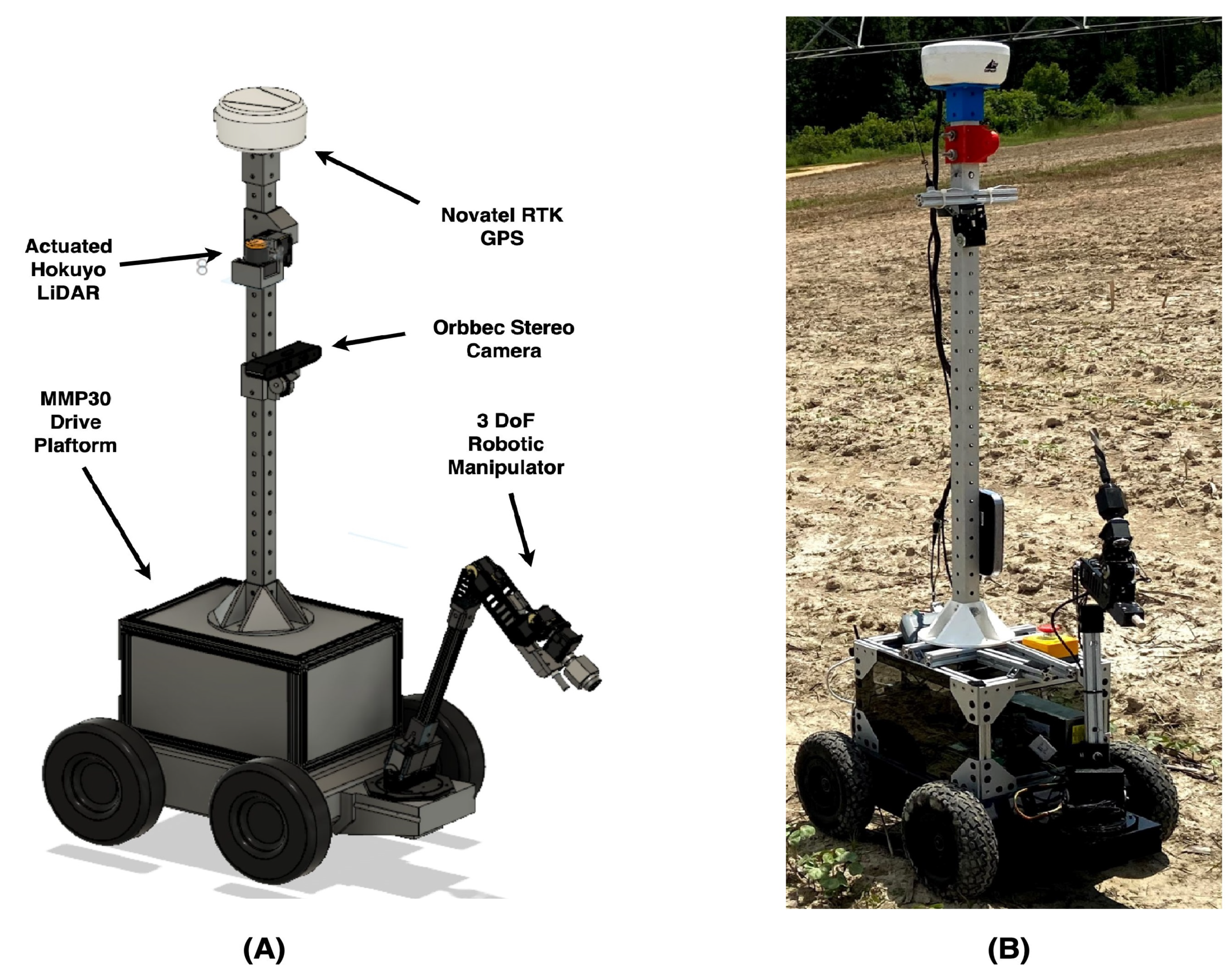
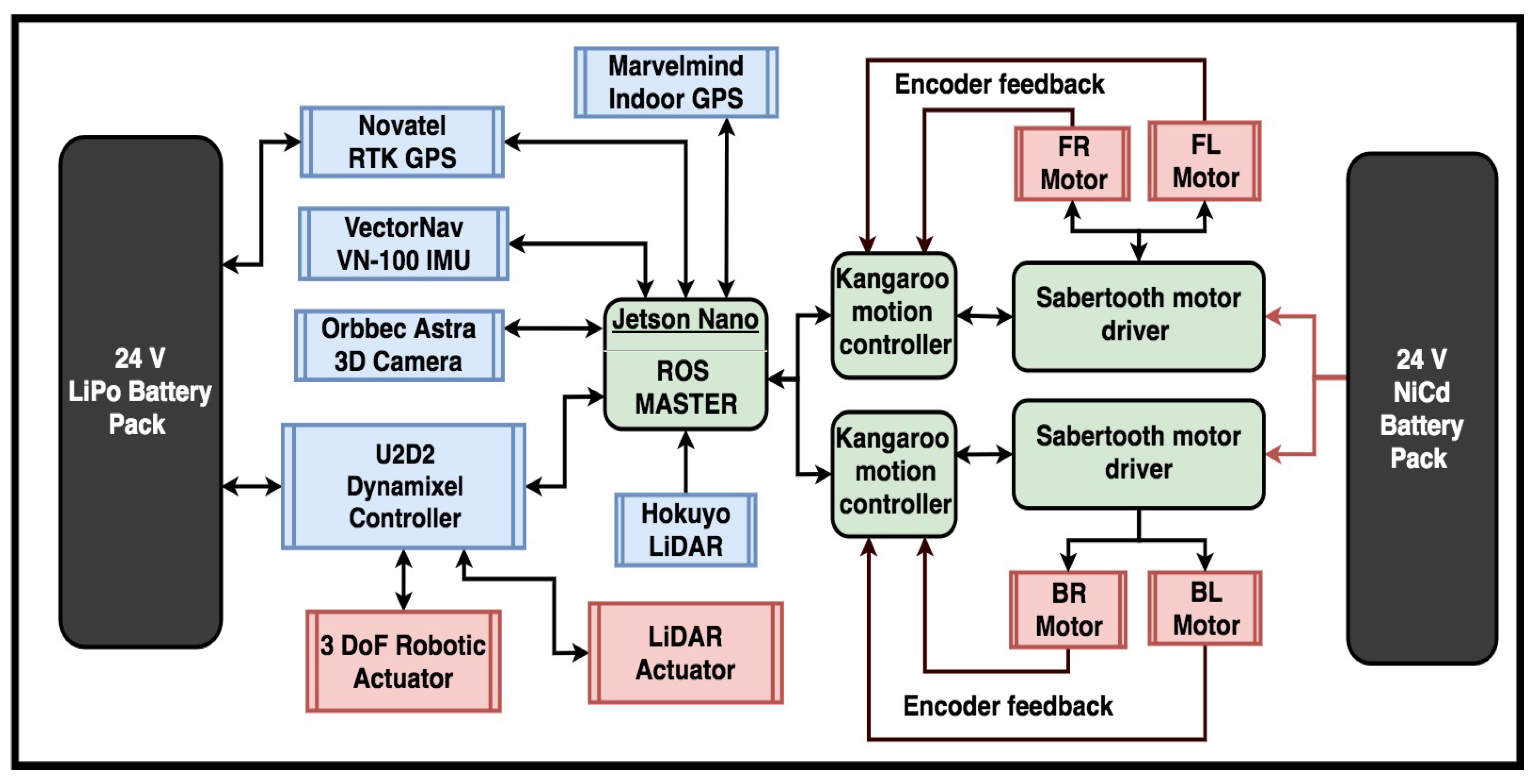
MARIA is an autonomous differential drive rover with various phenotyping sensors and a three DoF manipulator (Figure 1). The main computational system on board the MARIA rover is a Jetson Nano (Jetson Nano, Nvidia, CA, USA) running Ubuntu (an open-source Operating System using the Linux kernel, version 18.01) with the Robot Operating System (ROS Melodic). The overall system design is illustrated in Figure 2.
2.1. Autonomous Drive System
2.1.1. Drive System
The MARIA base consists of the chassis and drive system and is sourced from The Machine Lab (MMP30, The Machine Lab, Fort Collins, CO, USA). The MARIA has an extrusion based framing on top of the base which allows for an easily configurable and modular system for installing a variety of sensors and other components. The platform is equipped with two 25 V NiCad battery packs in parallel, with a total run time of approximately one hour at peak use. Each motor controller controls two, 24 V DC servo gearmotors with a stall torque of 6.07 N·m. Each motor is fitted with an optical encoder (HEDS 9100, Broadcom, CA, USA) that has a resolution of 500 counts per revolution (CPR). With a total gear reduction of 46:1 the encoder measurement accuracy for rotation is 0.0156 degrees. The motor control system consists of two Sabertooth dual 12 A motor drivers which are connected to a motion controller (Kangaroo, Dimension Engineering, OH, USA). The Kangaroo motion controller has a built in PID (proportional, integral, derivative) controller which can tune itself based on encoder information. The Kangaroo motor driver in turn communicates directly to the onboard single board computer (SBC) through a USB-TTL converter. The Kangaroo motion controller is communicated through packetized serial and the Arduino libraries provided by Dimension Engineering.
2.1.2. Localization
Multiple sensors were used for localization of the rover in an inertial frame. Wheel odometry was calculated using the wheel encoder feedback of the left and right DC motors. An inertial measurement unit (IMU) (VN-100, Vectornav, TX, USA) was used for measuring acceleration as well as heading. For global positioning two different sensor units were utilized. For localization in an outdoors environment a real time kinematic (RTK) GNSS was used (SMART6-L, Novatel, Calgary, AB, Canada). For an indoors environment a relative global positioning system was implemented (Marvelmind Indoor GPS, Marvelmind, Tallinn, Estonia). Marvelmind indoor GPS utilizes a set of stationary and mobile beacons that use ultrasonic signals to localize relative to each other using trilateration. These various localization signals were then input into an extended Kalman filter which allows for sensor fusion and output an accurate pose in a global environment. The extended Kalman filter was implemented through the robot_localization package [47]. The robot_localization package allows for arbitrary input of various localization sources into a Kalman filter as well as publish various transforms to the ROS tf library. The ROS tf library creates a transform tree from the map frame down to the robot base frame.
A calibration step is required for fusion of heading of the IMU and the heading using a global position system such as GPS or the Marvelmind beacons. This results from the IMU measuring headings typically based on magnetic north, which can be distorted by various surrounding magnetic sources while the global positioning system does not. As such, there is an offset needed to align the heading of the IMU and the heading of the global positioning system. This is done by calculating the heading in the global system by measuring two points to calculate a line and angle. The difference between the global positioning heading angle and the IMU is then applied to the IMU. The global position heading calculation using Global Navigation Satellite systems requires using UTM coordinates, which is defined by dividing the earth into respective square zones. Within these zones, Euclidean geometry is valid by assuming flatness.
Outdoor localization: GNSS based navigation was implemented for the MARIA using the “gps_common” package and navigation stack. Firstly, the correct transformations had to be implemented to convert GNSS goals in longitude/latitude into the MARIA’s frame of reference because latitude/longitude coordinates are defined in non-Euclidean space making it difficult for use in autonomous navigation. For this purpose, the “gps_common” node takes in latitude/longitude and outputs UTM coordinates.
Indoor localization: The MARIA is also compatible with the MarvelMind indoor GPS system for time of flight (ToF) based localization, which is useful for indoor applications such as greenhouses. This indoor navigation with absolute positioning is based on absolute global positions from ultrasonic beacons using the MarvelMind Indoor GPS. The indoor GPS beacons are able to get their relative positions from other beacons using ToF calculations of ultrasonic clicks. Using these relative positions, a map is created. A mobile beacon (also called a “hedgehog”) sits on the rover and has a mobile position with the origin designated at one of the stationary beacons. Marvelmind has a ROS package that enables the position of the mobile beacon to be published as a ROS topic. However for this global pose estimate to be fused with the robot_localization package, a publisher/subscriber node has to be created to adapt the raw position value into the “nav_msgs/Odometry” message.
2.1.3. Path Planning
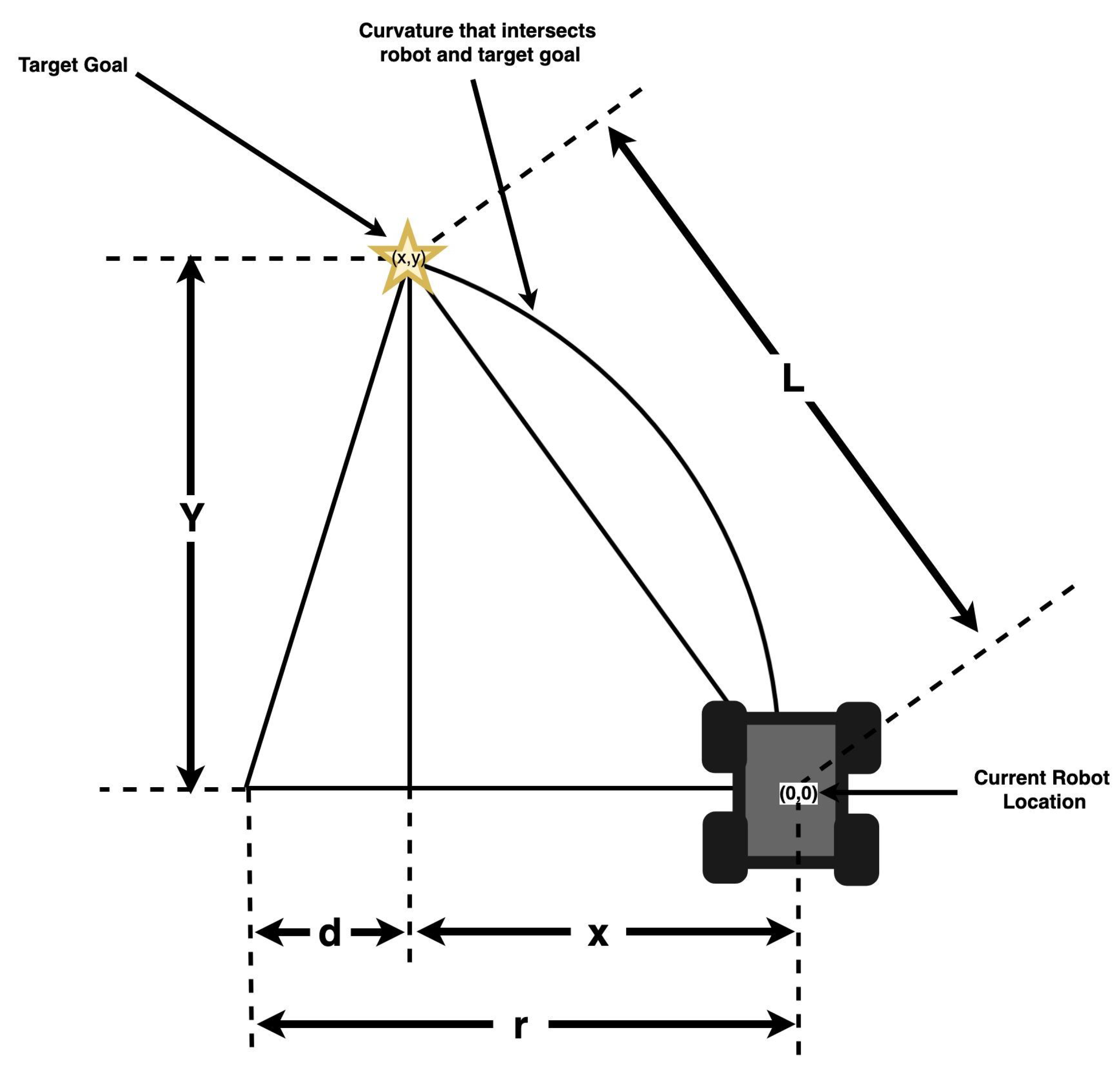
Pure pursuit was implemented as the planner of choice for the MARIA because of its simplicity and robust performance. Pure pursuits is a tracking algorithm developed in the 1980’s for calculating a curvature needed to get to a specific point (Figure 3) [48]. Pure pursuit geometrically calculates curvature needed to get to a specific point that is determined from a “look ahead” coordinate. The look ahead coordinate is a point on the desired path that is a “look ahead” distance away from the rover. A vector L is defined from origin to the look ahead coordinate. Using trigonometry these following equations can be defined:
From Equations (1)–(3), the curvature C that the robot has to follow to reach the look ahead coordinate can be determined in Equation (4). As the robot moves, the curvature is recalculated continuously as the look ahead point is updated continuously at a distance L. The robot is essentially continuously pursuing this point by following some curvature.
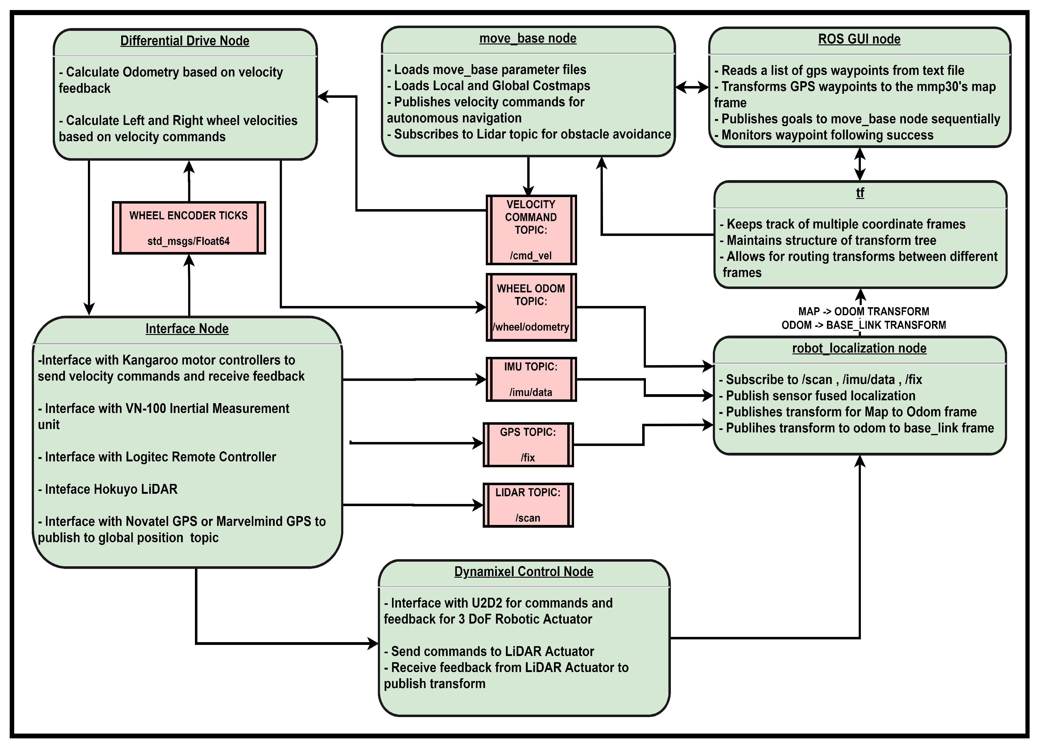
2.2. ROS Framework and Simulation
The Robot Operating System (ROS) was used as the central framework for data communication between all of MARIA’s subprocesses. One of the major sub processes is the autonomous driving capability. First, the autonomous driving starts with localization where for each sensor a node is started to publish to the appropriate topic (Figure 4). This is used as input to the robot localization ROS node that uses an extended Kalman filter to output a state estimate. The next major subprocess is the drive node, which takes feedback from the Kangaroo motion controllers on the rotation of the left and right wheels and then outputs them into the Diff-Drive node. The “Diff-Drive” node is used to calculate and publish odometry as well as accept velocity commands, translated from an overall velocity of the robot to the velocities of the left and right wheels. UART is used through the U2D2 to control the Dynamixel servos (Dynamixel Smart Servos, Robotis, Seoul, South Korea) which are used in both the onboard three DoF manipulators as well as for actuating a LiDAR unit. For managing autonomous navigation a “move_base” node was created. The “move_base” node is an implementation of the ROS navigation stack which allows a standardized interface to control the robot as well as to have feedback with a path planner of choice. The “move_base” node then outputs command velocity topics to reach its goal based on its current location/status. The “move_base” node outputs a velocity command directly to the “Diff-Drive node” which in turn sends right and left wheel velocities to follow the desired trajectory.
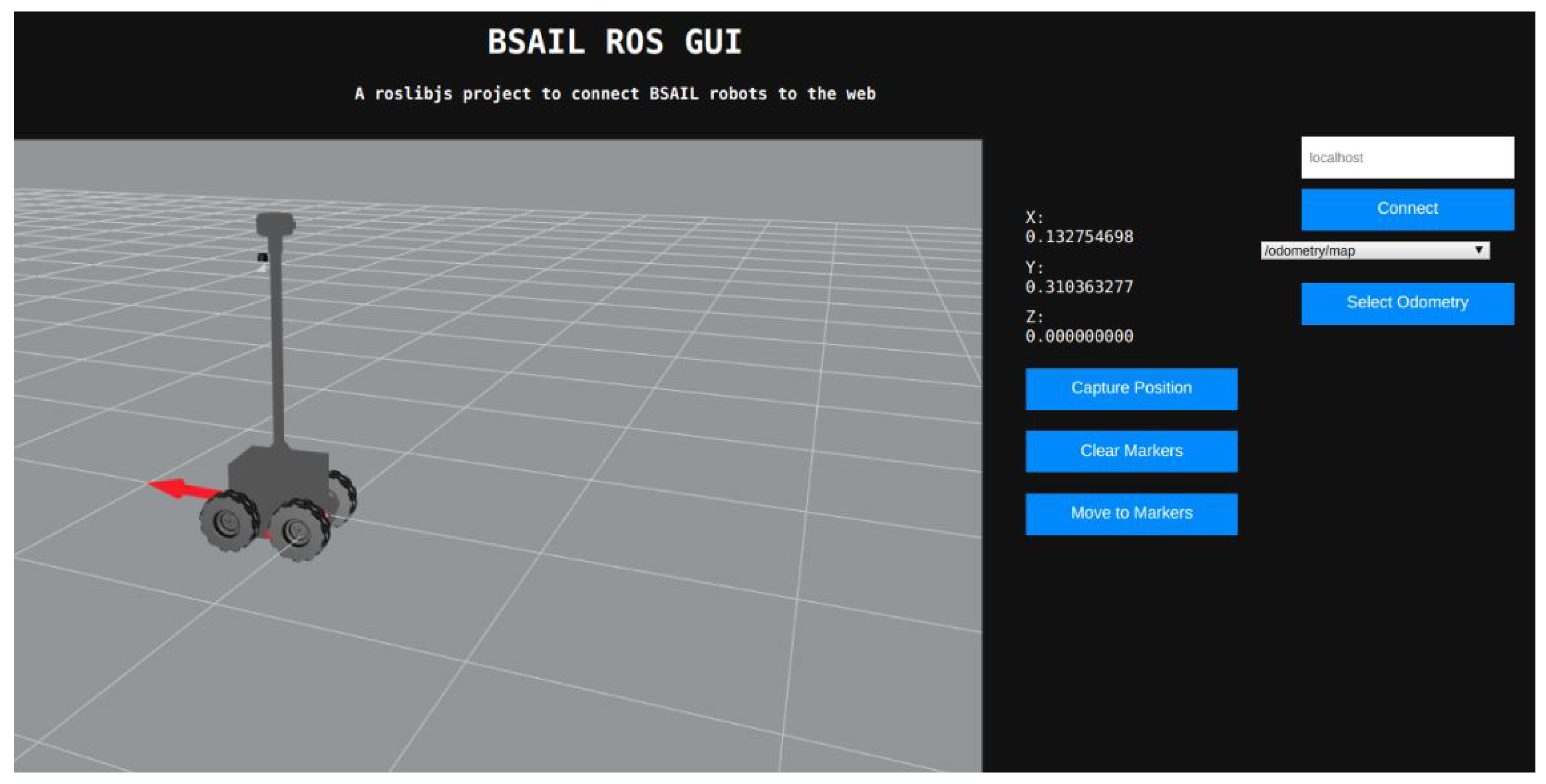
For high level control a Graphic User Interface (GUI) was added that provides a 3D RViz-like window to visualize the URDF, odometry heading, and present location of the robot in its TF “world_frame” (Figure 5). The GUI utilizes ROS, the HTML/CSS/JavaScript web stack, roslib.js, ros3d.js and the Apache web server to provide an intuitive interface to send position commands for robots in the field. The window is accompanied by a small amount of additional telemetry (odometry) as well as some interactive elements to control various parts of the client. Upon accessing the GUI via a web browser, the user can enter the IP address of the robot they wish to connect to, and select the odometry topic they wish to use for visualization from the drop down menu. Once the robot is connected, they can use the “Capture Position”, “Clear Markers”, and “Move to Markers” buttons to capture and display an odometry waypoint, clear existing odometry waypoints, or move the robot to existing odometry waypoints in the order they were captured.
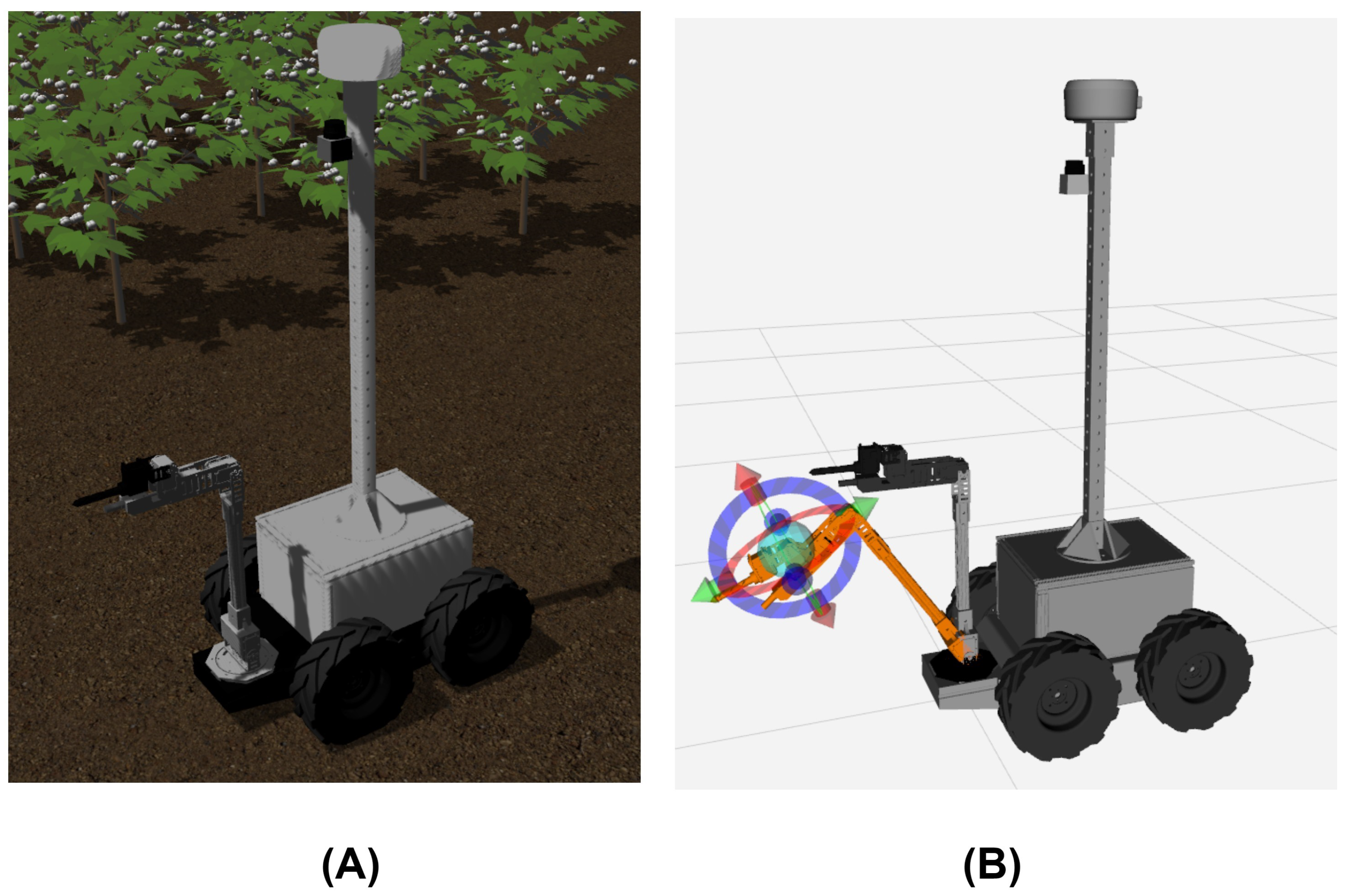
For prototyping and testing of the ROS system a simulation twin was created of MARIA using Gazebo (Figure 6A), a physics simulator, and ROS as the data communication interface. This simulation adds to our previous work with the addition of a three DoF manipulator [4]. A Universal Robot Description File (URDF) was generated from Solidworks using an URDF conversion plugin, and then revolute joints were added for the wheels and the manipulator joints. Using the URDF of the manipulator a ROS package Moveit was used to interface with the manipulator as well as to visualize manipulator movement (Figure 6B).
2.3. Mobile Manipulator
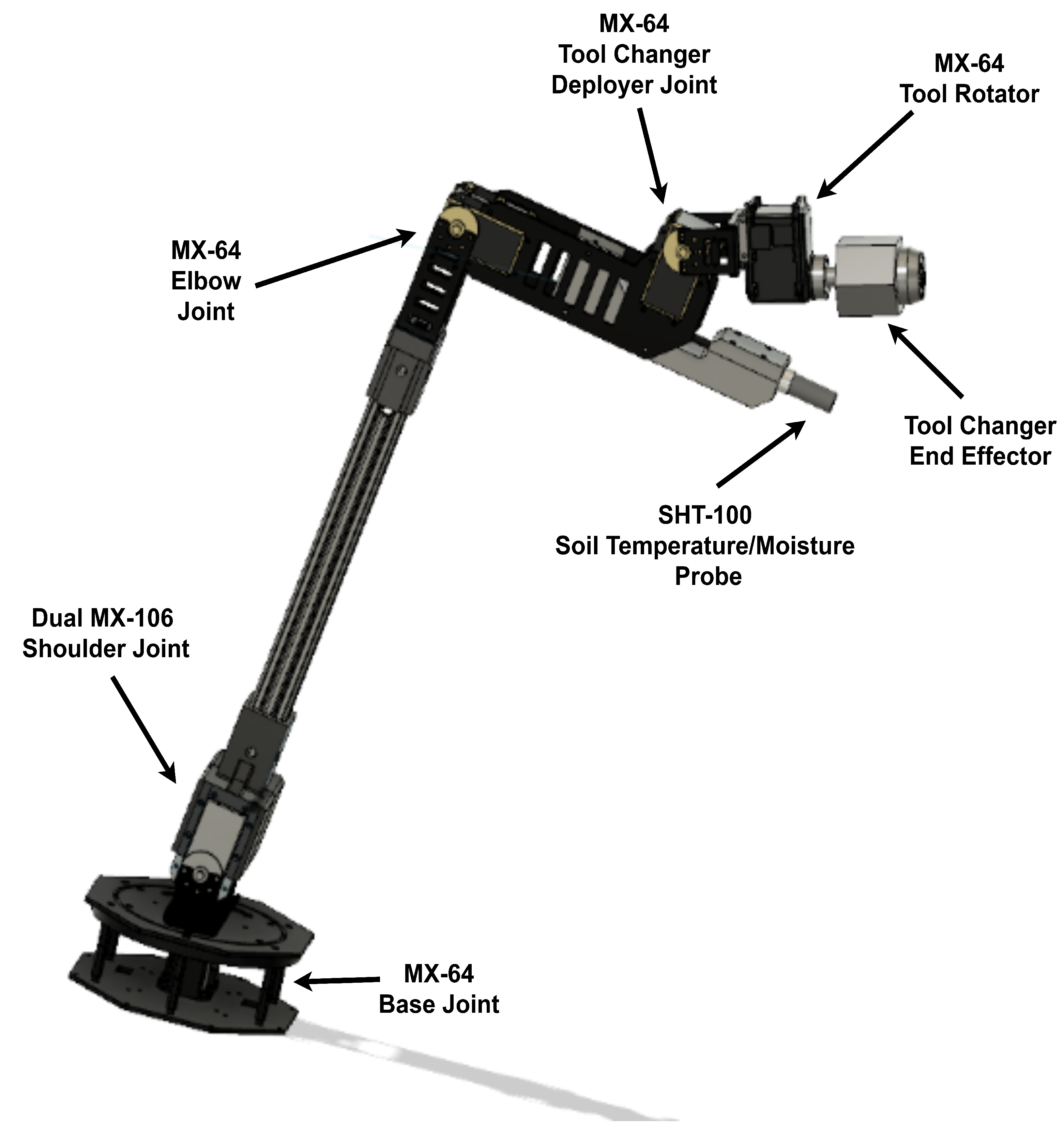
A 3 DoF actuator was developed using 3D printed joint connectors and the links being made of extrusion (Figure 7). The joints were designed to allow for different length extrusions to be connected, allowing for customization of the workspace of the onboard manipulator.
2.3.1. Multi-Purpose Toolhead
A toolhead was created for the Dynamixel end-effector to allow the changing of different end-effectors. The toolhead changer was inspired by the same mechanism as an electric screwdriver chuck, with which it is necessary to hold different tools and provide rotational force. The chuck functions through use of a rotational motion from the shaft that pushes the jaws forward and around different bits (Figure 8). For the jaws of the chuck to move around or out of a bit, the outside of the chuck has to be stationary, and as such, the outer case was made into an hexagonal shape. When the chuck is put into a hexagonal shaped tool changer, the outer case locks and allows the jaws to be positioned and grab onto the bit of the desired end-effector.
Various toolheads were designed and 3D printed to validate the toolhead changing capability of the robotic manipulator. One end-effector was a drill to penetrate soil and to allow for the insertion of a temperature and humidity probe that is later detailed in this paper. A prototype soil sampling cartridge was also designed with the ability to be picked up with the end toolhead changer and then be rotated into the soil. At the end of the cartridge are angled jaws that scrape the soil and then through the downward pressure of the cartridge exerted by the robotic manipulator the loosened soil pushes into the cartridge as it rotates. Once rotated down to a sufficient degree, the soil is compacted into the opening and later well lodged in the cartridge. Additionally the soil cartridge has a screw top opening allowing for easy opening to access gathered soil as well as for wash and reuse.
2.3.2. Servo Motors and the Control Library
The Dynamixel servos by Robotis was used for actuation of the joints. Dynamixels are a series of smart motors used extensively in this study’s robot system for actuation of both the onboard robotic manipulator and the Hokuyo LiDAR. They provide an ability to daisy-chain motors into a serial connection for convenient wiring of complex systems without requiring complex electrical harnesses to utilize many motors in robotic systems. Dynamixel motors use a UART serial data connection to send values to an internal control table allowing for velocity and position control as well as feedback from internal sensors such as current. Different models of motors are optimized for different usages and exist in different form factors, and each individual model uses a differently ordered internal control-table for the issuing of motor commands and variables. The control-table addresses the need to be specifically managed for each type of motor, causing difficulty implementing a hybrid system. For the purposes of solving this issue, a library was written alongside the overall system to implement an object-oriented method of communicating with many Dynamixel motors of any model rather than interfacing with the raw data values. Each individual motor is treated as an object of a generic motor, which has details of the motor populated as internal variables and functions depending on the motor requested. Each detail of the motor is stored as a JSON configuration for each possible motor using a Dynamixel protocol. By storing each address with its corresponding variable name as a string, similarities between the motors can be used to set motor parameters according to the name of the value desired to be viewed or modified rather than interfacing with a platform-dependent address value. For common motor functions such as setting motor velocity or reading motor position, the library implements dedicated function calls. Compared to use of specific control-table addresses, this addition allows for greater software reusability when addressing a control-table variable name which sometimes changes between models. This is also useful in situations of exchanging a motor between generations where the Dynamixel family began to use new naming conventions, as individual requirements per actuator could require use of specific models existing only in a certain generation. Other differences exist between the two generations which needed to be accounted for. The most prominent difference is that the Protocol 1.0 motors use 1’s complement encoding of negative numbers while Protocol 2.0 and most computers use 2’s complement.
2.3.3. Inverse Kinematics
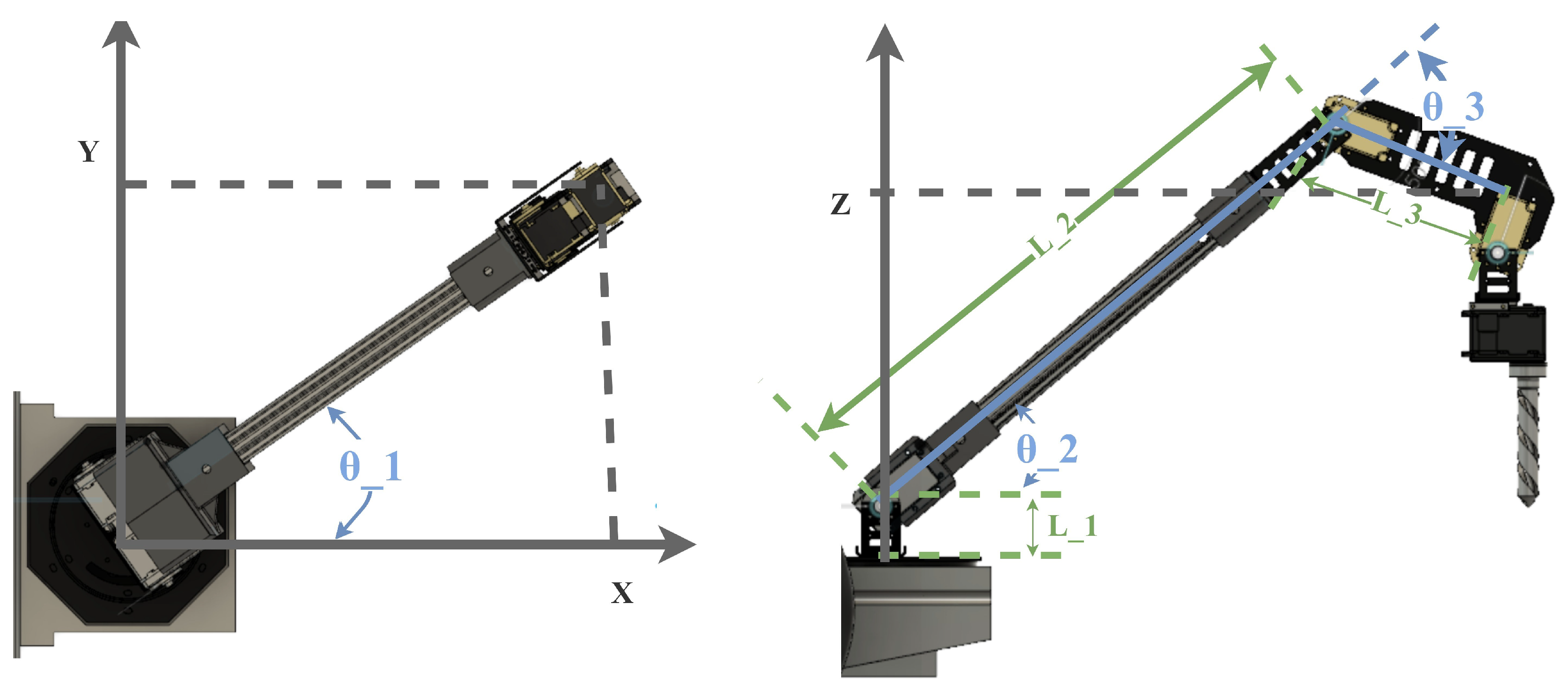
The analytical solution for the inverse kinematics for a 3 DoF articulated manipulator is presented through Equations (6) and (7) and Figure 9 [49]. General equations are provided because the robot arm was made of extrusion and it is possible to have various length configurations for the links and .
2.4. Phenotyping
2.4.1. Non-Contact Sensors
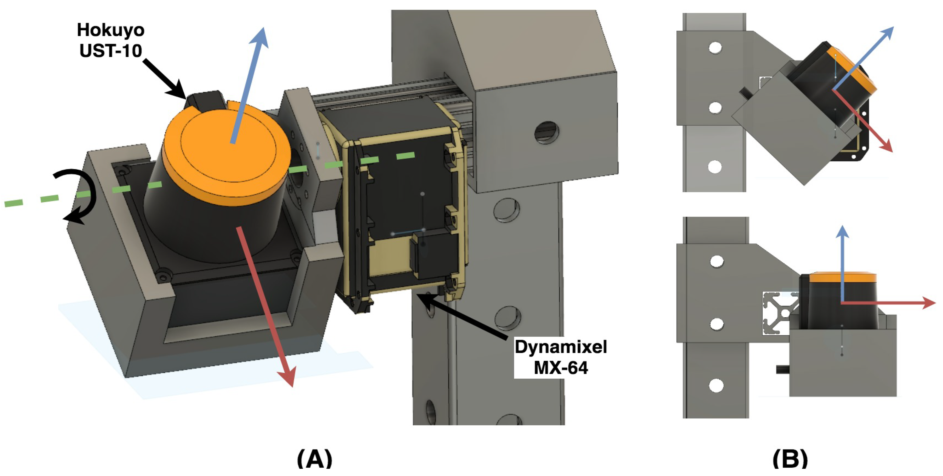
One of the phenotyping sensors on MARIA is an actuated Hokuyo UST-10 LiDAR (Hokuyo, Osaka, Japan). This 2D LiDAR is actuated in a 50 degree range around its y-axis (Figure 10). While the LiDAR unit is actuated, the feedback from the Dynamixel servo is used to apply a transform using the ROS transform library. This transform allows a 3D point cloud of the environment to be generated. An additional non-contact sensor onboard MARIA is an Astra 3D camera (Orbbec, MI, USA), which allows for generating point clouds as well as taking RGB images of the target area. The 3D camera could be used for volume estimation of crops.
2.4.2. Soil Sensing
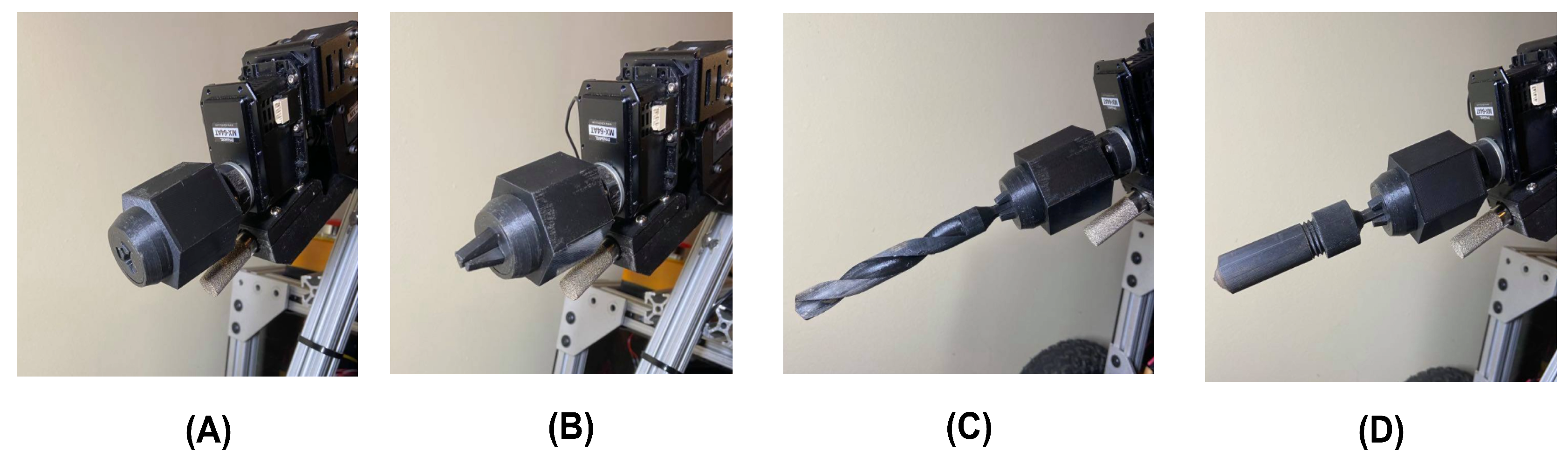
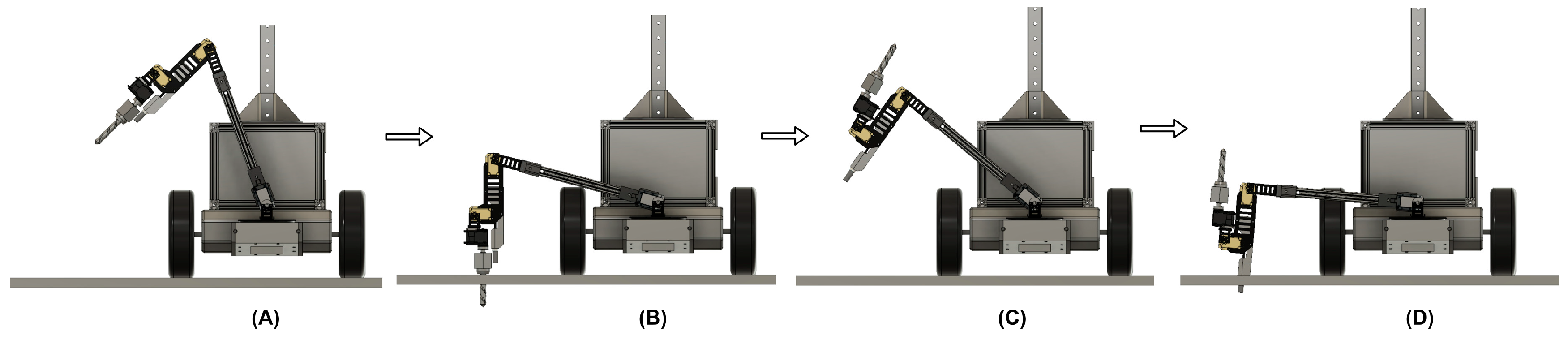
For soil sensing, a drill with an end bit was designed and coupled with a temperature and humidity sensor probe onboard the robot arm. The robotic arm first drills to a certain depth (Figure 11A,B) and then inserts a temperature and humidity probe into the soil (Figure 11C,D). This allows for root zone temperature and humidity measurements. The drill and probe are able to penetrate up to four inches into the soil.
3. Performance Testing Results and Discussion
3.1. Navigation
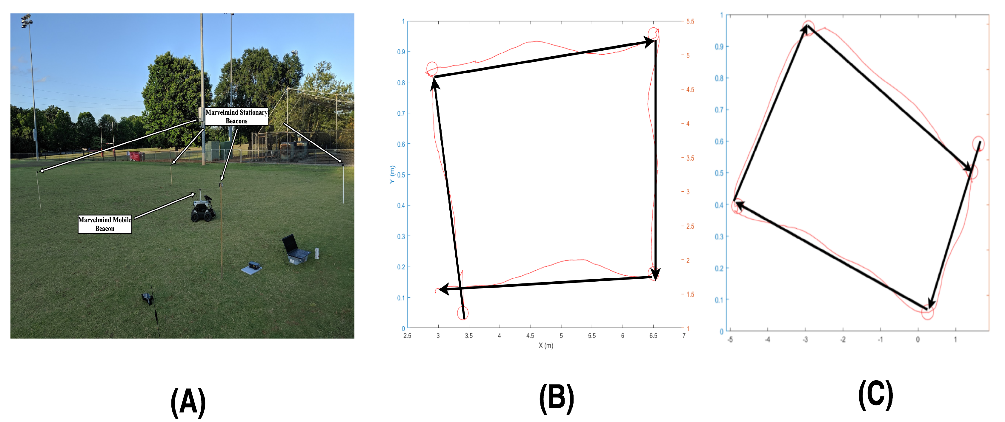
Navigation was performed outdoors with two different global localization sensors. For the first global positioning system, the Marvelmind ultrasonic beacons were used and mounted on posts around the robot (Figure 12A). The robot was given four global waypoints to navigate to. The RMSE for Marvelmind beacon based navigation was 0.1566 m (Figure 12B). The second localization method used was using the SMART-6 Novatel RTK GPS. The RTK GPS based navigation resulted in an RMSE of 0.2692 m (Figure 12C).
3.2. Non-Contact Phenotyping
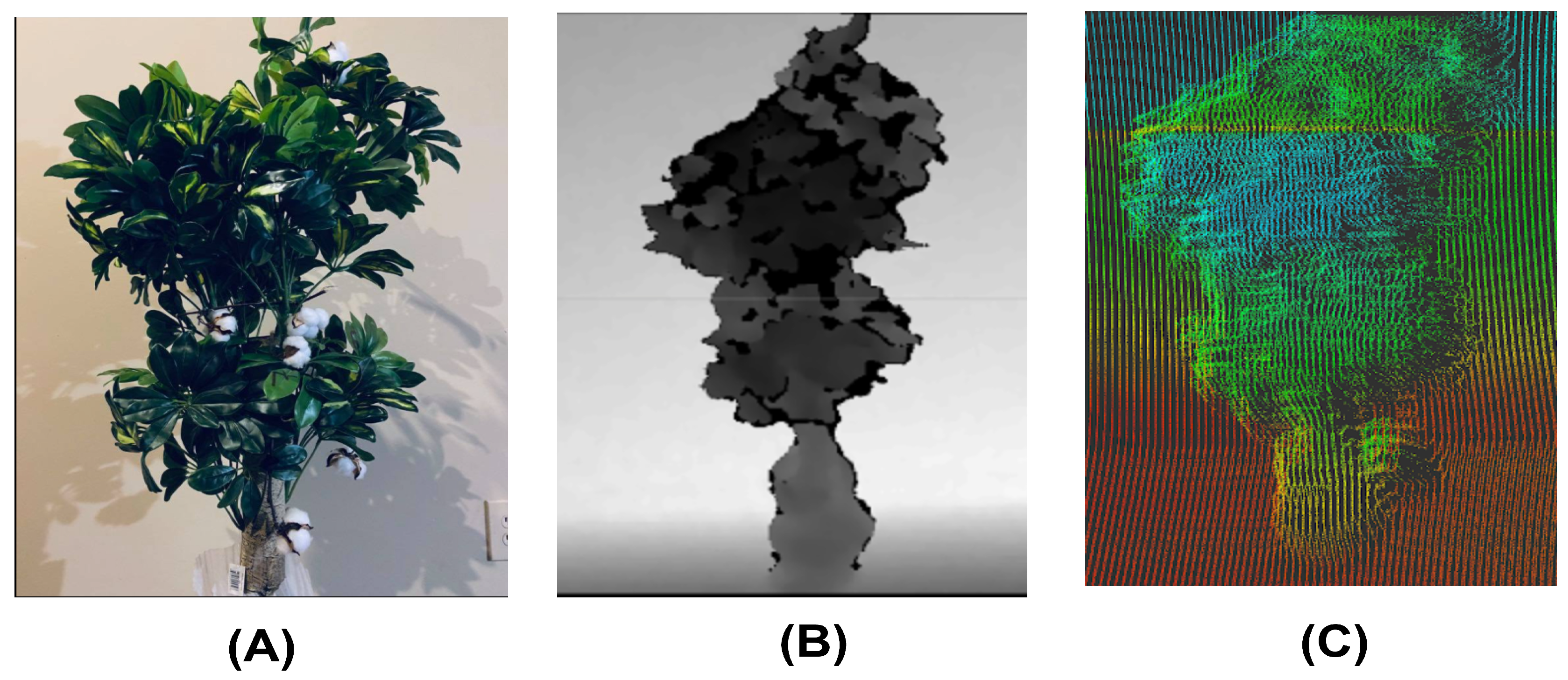
The ability of the onboard non-contact sensors were tested and they showed different capabilities to potentially capture various phenotypic traits (Figure 13). For example, the 3D camera is able to generate depth images as well as to take RGB images, while the actuated LiDAR is able to generate a point cloud. In this study, the actuated LiDAR was primarily tested.
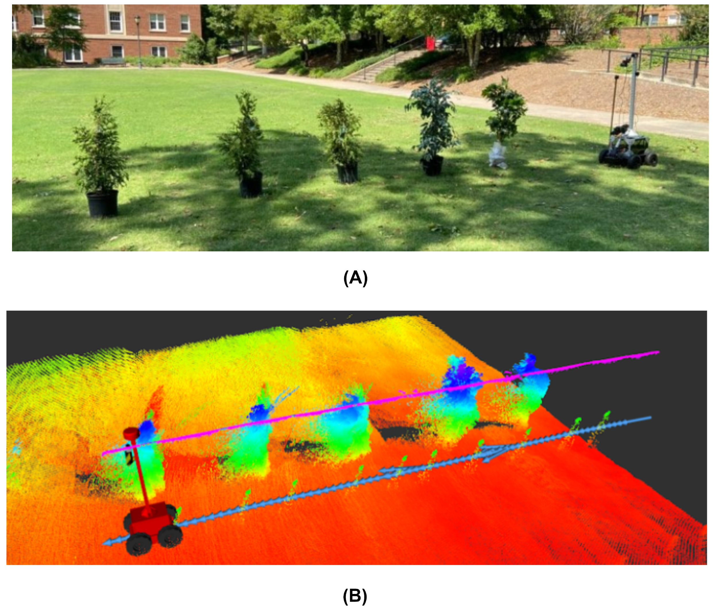
For validation of the phenotyping capability of the actuated LiDAR configuration for MARIA, five plants of various sizes were placed in a line while the rover drove parallel to the plants collecting point cloud data (Figure 14).
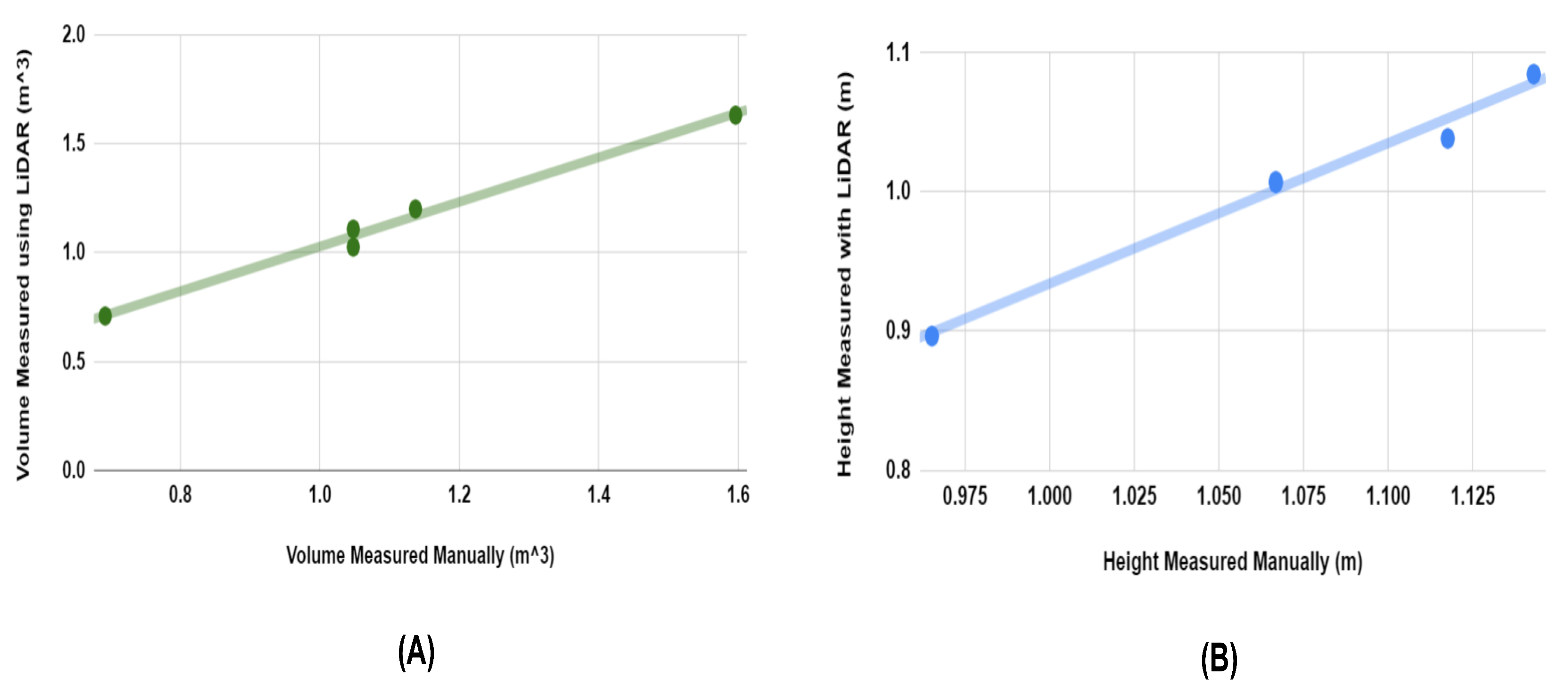
The volume of a cylinder was calculated for each increment and aggregated to estimate the volume of the plant. For the LiDAR validation experiment the actuated LiDAR rotated 50 degrees in 5 s allowing for a full “nod” period of 10 s. MARIA was moved at a velocity of 0.1 m/s parallel to the row of plants. The point cloud was generated from the laser scan using the “laser_assembler” ROS package and then post processed in MATLAB (Figure 15). Within MATLAB the volume was ascertained using the convex hull function with a shrink factor of 0. The resultant volume estimation was then scaled by a factor of 4 to compensate for the underestimation from the limited view from the point cloud generated by LiDAR. The ground truth for the volume of the plants was determined manually by measuring the width of the plants at multiple increments along the height of the plant. The resulting volume estimation had of 0.989, a RMSE 0.0435 and an average percentage error of 1.76%.
Another phenotypic trait being measured was the plant height. For height measurement, a random sample consensus (RANSAC) algorithm was used to measure the ground plane. Then the point cloud was analyzed to find the highest point and its height relative to the ground plane. Using this height measurement method, the proposed strategy had an of 0.984, a RMSE of 0.068 and an average percentage error of 3.2%.
3.3. Soil Sensing
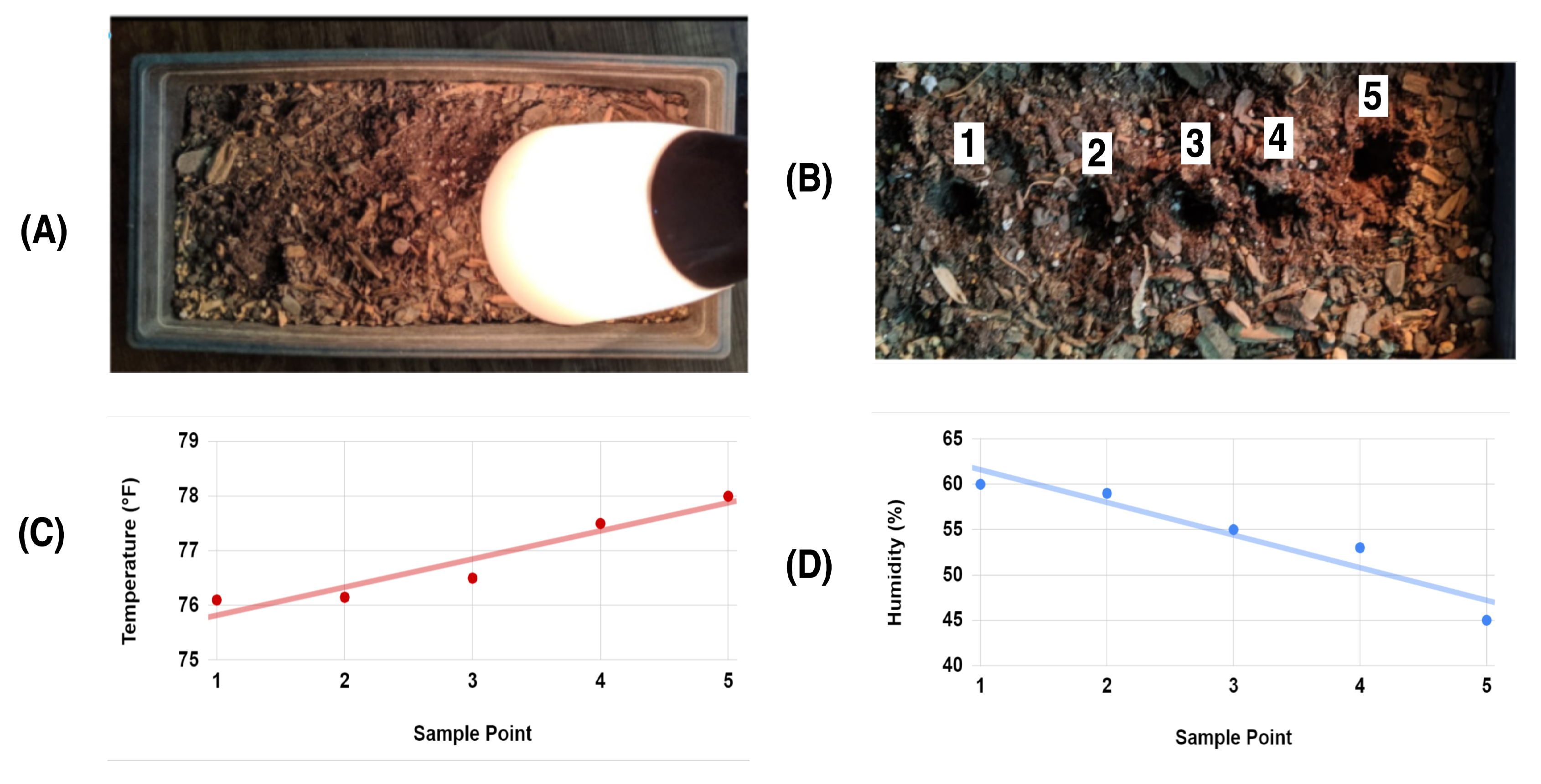
The soil sensing capability of the onboard robotic manipulator was tested in a controlled setting by first shining a lamp on a soil pot for two hours and then having the robotic arm to collect temperature and moisture data at five spots with approximately two inch increments along the soil pot (Figure 16). The temperature and moisture probe was able to measure the positive temperature and negative moisture change along the pot due to being exposed to a heat lamp. Based on a line fit with an value of 0.908, the rate of change of the temperature was 0.112 degrees Celsius per centimeter. For moisture change, a line fit with an value of 0.905 was attained and an estimated moisture change was −1.41% pr centimeter.
Lastly, a test was conducted to assess the ability of MARIA to combine global navigation and soil sensing by commanding MARIA to move to a specific global waypoint and then use the mobile actuator to drill and insert the temperature and humidity probe into a pot filled with soil. The four soil pots were put into multiple configurations such as a square, a straight line, and a random, unstructured configuration. Waypoints were determined by driving the rover to a specific position and recording its position and heading. Each pot was six inches in diameter resulting in 28.3 area for the manipulator to drill and insert probe. One test was conducted for each of the configurations. MARIA was able to gather data with 100% success for square and line configurations. However for random configuration, the manipulator was unsuccessful in sensing one of the four potted plants resulting in an average success rate of 91.7% for all tests (Table 1).
A mechanical design as well as phenotyping and navigation systems were proposed for MARIA and validated in a controlled setting. Navigation was tested using both indoor and outdoor global localization systems and was able to perform with a low root mean square error. An integrated robot operating system was presented that handles sensor data, localization, and navigation as well as a web based GUI to allow setting waypoints. Additionally a soil sensing manipulator was designed and implemented. Its ability to measure temperature and humidity was validated in a conditioned soil pot. Finally, the navigation system and soil sensing system were combined and allowed the rover to reach a specific global waypoint and perform a temperature and humidity sensing operation. With an actuated LiDAR, MARIA was also able to perform non-contact phenotyping with low percent error in plant height and volume estimation.
Future research can introduce several improvements to be implemented on the system. The drive system for MARIA is able to drive well in flat settings but is sensitive to bumps and uneven ground. As such the addition of a suspension system to the rover would reduce disturbances. The manipulator onboard MARIA could be improved with better actuators that are able to handle larger loads. With higher torque the motors can handle harder soil. Additionally more degrees of freedom can be added to manipulators to handle more complex manipulation tasks that could be tailored to the specific needs of the crop of interest. The soil sampling end-effector could also be further improved by adding the ability to eject soil samples into an internal soil storage container or store and collect a new soil sampling cartridge.
4. Conclusions
In this paper a multipurpose agriculture robot, named MARIA, was proposed and designed using off-the-shelf components. An autonomous drive system was designed using ROS to perform GNSS-guided navigation and waypoint following. The phenotyping capability for MARIA was validated using an actuated LiDAR for measuring important phenotypic traits such as volume and height. A mobile three-DoF manipulator was designed for MARIA with a multipurpose end-effector which could be changed to adapt to other tasks such as collecting soil samples and measuring root zone temperature and moisture. This study contributes to the field by presenting a design capable of both LiDAR phenotyping and soil sensing that could be easily replicated through the use of off-the-shelf and 3D printed components. Future work will be aimed at improving the robustness and ease of use of this system in the field.
Author Contributions
Conceptualization, C.L. and J.I.; methodology and software, J.I., R.X., H.H.; formal analysis, J.I.; writing—original draft preparation, J.I. and C.L.; writing—review and editing, C.L.; supervision, C.L.; project administration, C.L.; funding acquisition, C.L. All authors have read and agreed to the published version of the manuscript.
Funding
This research was supported by the funding from the National Robotics Initiative (NIFA grant No. 2017-67021-25928), Cotton Incorporated (17-510GA) and Georgia Cotton Commission.
Acknowledgments
The authors want to thank Kevin Koffroth and William Snapp for their assistance on ROS GUI design and end-effector design and fabrication.
Conflicts of Interest
The authors declare no conflict of interest.
References
- Godfray, H.C.J.; Beddington, J.R.; Crute, I.R.; Haddad, L.; Lawrence, D.; Muir, J.F.; Pretty, J.; Robinson, S.; Thomas, S.M.; Toulmin, C. Food security: The challenge of feeding 9 billion people. Science 2010, 327, 812–818. [Google Scholar] [CrossRef] [Green Version]
- Yang, W.; Duan, L.; Chen, G.; Xiong, L.; Liu, Q. Plant phenomics and high-throughput phenotyping: Accelerating rice functional genomics using multidisciplinary technologies. Curr. Opin. Plant Biol. 2013, 16, 180–187. [Google Scholar] [CrossRef]
- Andrés, F.; Coupland, G. The genetic basis of flowering responses to seasonal cues. Nat. Rev. Genet. 2012, 13, 627–639. [Google Scholar] [CrossRef]
- Iqbal, J.; Xu, R.; Sun, S.; Li, C. Simulation of an Autonomous Mobile Robot for LiDAR-Based In-Field Phenotyping and Navigation. Robotics 2020, 9, 46. [Google Scholar] [CrossRef]
- Mueller-Sim, T.; Jenkins, M.; Abel, J.; Kantor, G. The Robotanist: A ground-based agricultural robot for high-throughput crop phenotyping. In Proceedings of the 2017 IEEE International Conference on Robotics and Automation (ICRA), Singapore, 29 May–3 June 2017; pp. 3634–3639. [Google Scholar] [CrossRef]
- Shafiekhani, A.; Kadam, S.; Fritschi, F.B.; DeSouza, G.N. Vinobot and Vinoculer: Two Robotic Platforms for High-Throughput Field Phenotyping. Sensors 2017, 17, 214. [Google Scholar] [CrossRef] [PubMed]
- Kayacan, E.; Zhang, Z.; Chowdhary, G. Embedded High Precision Control and Corn Stand Counting Algorithms for an Ultra-Compact 3D Printed Field Robot. In Proceedings of the Robotics: Science and Systems XIV, Pittsburgh, PA, USA, 26–30 June 2018. [Google Scholar]
- Ruckelshausen, A.; Biber, P.; Dorna, M.; Gremmes, H.; Klose, R.; Linz, A.; Rahe, F.; Resch, R.; Thiel, M.; Trautz, D. BoniRob—An autonomous field robot platform for individual plant phenotyping. Precis. Agric. 2009, 9, 1. [Google Scholar]
- Grimstad, L.; From, P.J. The Thorvald II Agricultural Robotic System. Robotics 2017, 6, 24. [Google Scholar] [CrossRef] [Green Version]
- Stager, A.; Tanner, H.G.; Sparks, E.E. Design and Construction of Unmanned Ground Vehicles for Sub-Canopy Plant Phenotyping. arXiv 2019, arXiv:cs.RO/1903.10608. [Google Scholar]
- Bonadies, S.; Gadsden, S.A. An overview of autonomous crop row navigation strategies for unmanned ground vehicles. Eng. Agric. Environ. Food 2019, 12, 24–31. [Google Scholar] [CrossRef]
- Bakker, T.; Asselt, K.; Bontsema, J.; Müller, J.; Straten, G. Systematic design of an autonomous platform for robotic weeding. J. Terramech. 2010, 47, 63–73. [Google Scholar] [CrossRef]
- Nagasaka, Y.; Saito, H.; Tamaki, K.; Seki, M.; Kobayashi, K.; Taniwaki, K. An autonomous rice transplanter guided by global positioning system and inertial measurement unit. J. Field Robot. 2009, 26, 537–548. [Google Scholar] [CrossRef]
- Blackmore, B.; Griepentrog, H.W.; Nielsen, H.; Nørremark, M.; Resting-Jeppesen, J. Development of a deterministic autonomous tractor. In Proceedings of the CIGR Conference, Kyoto, Japan, 7–8 October 2004. [Google Scholar]
- Yang, L.; Noguchi, N. Development of a Wheel-Type Robot Tractor and its Utilization. In Proceedings of the 19th IFAC World Congress, Cape Town, South Africa, 25–29 August 2014; Volume 47, pp. 11571–11576. [Google Scholar] [CrossRef] [Green Version]
- Samuel, M.; Hussein, M.; Mohamad, M.B. A review of some pure-pursuit based path tracking techniques for control of autonomous vehicle. Int. J. Comput. Appl. 2016, 135, 35–38. [Google Scholar] [CrossRef]
- Normey-Rico, J.E.; Alcalá, I.; Gómez-Ortega, J.; Camacho, E.F. Mobile robot path tracking using a robust PID controller. Control Eng. Pract. 2001, 9, 1209–1214. [Google Scholar] [CrossRef]
- Luo, X.; Zhang, Z.; Zhao, Z.; Chen, B.; Hu, L.; Wu, X. Design of DGPS navigation control system for Dongfanghong X-804 tractor. Nongye Gongcheng Xuebao/Trans. Chin. Soc. Agric. Eng. 2009, 25, 139–145. [Google Scholar] [CrossRef]
- Qiu, R.; Wei, S.; Zhang, M.; Li, H.; Sun, H.; Liu, G.; Li, M. Sensors for measuring plant phenotyping: A review. Int. J. Agric. Biol. Eng. 2018, 11, 1–17. [Google Scholar] [CrossRef] [Green Version]
- Jiang, Y.; Snider, J.L.; Li, C.; Rains, G.C.; Paterson, A.H. Ground based hyperspectral imaging to characterize canopy-level photosynthetic activities. Remote Sens. 2020, 12, 315. [Google Scholar] [CrossRef] [Green Version]
- Zhang, M.; Jiang, Y.; Li, C.; Yang, F. Fully convolutional networks for blueberry bruising and calyx segmentation using hyperspectral transmittance imaging. Biosyst. Eng. 2020, 192, 159–175. [Google Scholar] [CrossRef]
- Xu, R.; Li, C.; Paterson, A. Multispectral imaging and unmanned aerial systems for cotton plant phenotyping. PLoS ONE 2019, 14, e0205083. [Google Scholar] [CrossRef] [Green Version]
- Wang, H.; Lin, Y.; Wang, Z.; Yao, Y.; Zhang, Y.; Wu, L. Validation of a low-cost 2D laser scanner in development of a more-affordable mobile terrestrial proximal sensing system for 3D plant structure phenotyping in indoor environment. Comput. Electron. Agric. 2017, 140, 180–189. [Google Scholar] [CrossRef]
- Pabuayon, I.L.B.; Sun, Y.; Guo, W.; Ritchie, G.L. High-throughput phenotyping in cotton: A review. J. Cotton Res. 2019, 2, 18. [Google Scholar] [CrossRef]
- Sun, S.; Li, C.; Paterson, A.H.; Jiang, Y.; Xu, R.; Robertson, J.S.; Snider, J.L.; Chee, P.W. In-field High Throughput Phenotyping and Cotton Plant Growth Analysis Using LiDAR. Front. Plant Sci. 2018, 9, 16. [Google Scholar] [CrossRef] [PubMed] [Green Version]
- Jimenez-Berni, J.A.; Deery, D.M.; Rozas-Larraondo, P.; Condon, A.T.G.; Rebetzke, G.J.; James, R.A.; Bovill, W.D.; Furbank, R.T.; Sirault, X.R.R. High Throughput Determination of Plant Height, Ground Cover, and Above-Ground Biomass in Wheat with LiDAR. Front. Plant Sci. 2018, 9, 237. [Google Scholar] [CrossRef] [PubMed] [Green Version]
- Llop, J.; Gil, E.; Llorens, J.; Miranda-Fuentes, A.; Gallart, M. Testing the Suitability of a Terrestrial 2D LiDAR Scanner for Canopy Characterization of Greenhouse Tomato Crops. Sensors 2016, 16, 1435. [Google Scholar] [CrossRef] [PubMed] [Green Version]
- White, J.W.; Andrade-Sanchez, P.; Gore, M.A.; Bronson, K.F.; Coffelt, T.A.; Conley, M.M.; Feldmann, K.A.; French, A.N.; Heun, J.T.; Hunsaker, D.J.; et al. Field-based phenomics for plant genetics research. Field Crops Res. 2012, 133, 101–112. [Google Scholar] [CrossRef]
- Harchowdhury, A.; Kleeman, L.; Vachhani, L. Coordinated Nodding of a Two-Dimensional Lidar for Dense Three-Dimensional Range Measurements. IEEE Robot. Autom. Lett. 2018, 3, 4108–4115. [Google Scholar] [CrossRef]
- Malavazi, F.B.P.; Guyonneau, R.; Fasquel, J.B.; Lagrange, S.; Mercier, F. LiDAR-only based navigation algorithm for an autonomous agricultural robot. Comput. Electron. Agric. 2018, 154, 71–79. [Google Scholar] [CrossRef]
- Passioura, J.B. Phenotyping for drought tolerance in grain crops: When is it useful to breeders? Funct. Plant Biol. 2012, 39, 851–859. [Google Scholar] [CrossRef]
- Bitella, G.; Rossi, R.; Bochicchio, R.; Perniola, M.; Amato, M. A novel low-cost open-hardware platform for monitoring soil water content and multiple soil-air-vegetation parameters. Sensors 2014, 14, 19639–19659. [Google Scholar] [CrossRef] [Green Version]
- Nakamoto, T. Gravitropic reaction of primary seminal roots of Zea mays L. influenced by temperature and soil water potential. J. Plant Res. 1995, 108, 71–75. [Google Scholar] [CrossRef]
- He, Y.; Yang, J.; Zhu, B.; Zhu, Z. Low Root Zone Temperature Exacerbates the Ion Imbalance and Photosynthesis Inhibition and Induces Antioxidant Responses in Tomato Plants Under Salinity. J. Integr. Agric. 2014, 13, 89–99. [Google Scholar] [CrossRef] [Green Version]
- Watt, M.; Silk, W.K.; Passioura, J.B. Rates of root and organism growth, soil conditions, and temporal and spatial development of the rhizosphere. Ann. Bot. 2006, 97, 839–855. [Google Scholar] [CrossRef] [PubMed] [Green Version]
- Pobkrut, T.; Kerdcharoen, T. Soil sensing survey robots based on electronic nose. In Proceedings of the 2014 14th International Conference on Control, Automation and Systems (ICCAS 2014), Gyeonggi, Korea, 22–25 October 2014; pp. 1604–1609. [Google Scholar]
- Scholz, C.; Moeller, K.; Ruckelshausen, A.; Hinck, S.; Goettinger, M. Automatic soil penetrometer measurements and GIS based documentation with the autonomous field robot platform bonirob. In Proceedings of the 12th International Conference of Precision Agriculture, Sacramento, CA, USA, 20–23 July 2014. [Google Scholar]
- ukowska, A.; Tomaszuk, P.; Dzierżek, K.; Magnuszewski, Ł. Soil sampling mobile platform for Agriculture 4.0. In Proceedings of the 2019 20th International Carpathian Control Conference (ICCC), Wieliczka, Poland, 26–29 May 2019; pp. 1–4. [Google Scholar]
- Van Der Weide, R.Y.; Bleeker, P.O.; Achten, V.T.J.M.; Lotz, L.A.P.; Fogelberg, F.; Melander, B. Innovation in mechanical weed control in crop rows. Weed Res. 2008, 48, 215–224. [Google Scholar] [CrossRef]
- Åstrand, B.; Baerveldt, A.J. An Agricultural Mobile Robot with Vision-Based Perception for Mechanical Weed Control. Auton. Robot. 2002, 13, 21–35. [Google Scholar] [CrossRef]
- Gonzalez-de Santos, P.; Ribeiro, A.; Fernandez-Quintanilla, C.; Lopez-Granados, F.; Brandstoetter, M.; Tomic, S.; Pedrazzi, S.; Peruzzi, A.; Pajares, G.; Kaplanis, G.; et al. Fleets of robots for environmentally-safe pest control in agriculture. Precis. Agric. 2017, 18, 574–614. [Google Scholar] [CrossRef]
- Bogue, R. Robots poised to revolutionise agriculture. Ind. Rob. 2016, 43, 450–456. [Google Scholar] [CrossRef]
- Bao, Y.; Zarecor, S.; Shah, D.; Tuel, T.; Campbell, D.A.; Chapman, A.V.; Imberti, D.; Kiekhaefer, D.; Imberti, H.; Lübberstedt, T. Assessing plant performance in the Enviratron. Plant Methods 2019, 15, 1–14. [Google Scholar] [CrossRef] [Green Version]
- Hassan, M.U.; Ullah, M.; Iqbal, J. Towards autonomy in agriculture: Design and prototyping of a robotic vehicle with seed selector. In Proceedings of the 2016 2nd International Conference on Robotics and Artificial Intelligence (ICRAI), Los Angeles, CA, USA, 18–19 May 2016; pp. 37–44. [Google Scholar]
- Rahul, K.; Raheman, H.; Paradkar, V. Design and development of a 5R 2DOF parallel robot arm for handling paper pot seedlings in a vegetable transplanter. Comput. Electron. Agric. 2019, 166, 105014. [Google Scholar] [CrossRef]
- Bascetta, L.; Baur, M.; Gruosso, G. ROBI’: A Prototype Mobile Manipulator for Agricultural Applications. Electronics 2017, 6, 39. [Google Scholar] [CrossRef] [Green Version]
- Moore, T.; Stouch, D. A Generalized Extended Kalman Filter Implementation for the Robot Operating System. In Proceedings of the 13th International Conference on Intelligent Autonomous Systems (IAS-13), Padova, Italy, 15–18 July 2014; Springer: Berlin/Heidelberg, Germany, 2014. [Google Scholar]
- Coulter, R.C. Implementation of the Pure Pursuit Path Tracking Algorithm; Technical Report; Carnegie-Mellon UNIV Pittsburgh PA Robotics INST: Pittsburgh, PA, USA, 1992. [Google Scholar]
- Siciliano, B.; Sciavicco, L.; Villani, L.; Oriolo, G. Robotics: Modelling, Planning and Control; Springer Science & Business Media: Berlin/Heidelberg, Germany, 2010. [Google Scholar]
Figure 1.
MARIA: An autonomous differential drive rover. (A) CAD model of Multipurpose Autonomous Robot of Intelligent Agriculture (MARIA); (B) Picture of MARIA.
Figure 1.
MARIA: An autonomous differential drive rover. (A) CAD model of Multipurpose Autonomous Robot of Intelligent Agriculture (MARIA); (B) Picture of MARIA.

Figure 2.
A diagram of the overall system design for MARIA.

Figure 3.
Geometric relationships for the pure pursuit path planner.

Figure 4.
Simplified Robot Operating System (ROS) node diagram.

Figure 5.
Graphic User Interface (GUI) for MARIA.

Figure 6.
Simulation of the robot in (A) Gazebo and (B) Moveit RViz Visualizer in Robot Operating System (ROS).
Figure 6.
Simulation of the robot in (A) Gazebo and (B) Moveit RViz Visualizer in Robot Operating System (ROS).

Figure 7.
CAD model of the manipulator.

Figure 8.
Multipurpose toolhead at the end of the manipulator. (A) Toolhead with jaws retracted; (B) Toolhead with jaws extended; (C) Toolhead with a soil drill bit; (D) Toolhead with a soil sampler.
Figure 8.
Multipurpose toolhead at the end of the manipulator. (A) Toolhead with jaws retracted; (B) Toolhead with jaws extended; (C) Toolhead with a soil drill bit; (D) Toolhead with a soil sampler.

Figure 9.
Geometric relationships for inverse kinematics.

Figure 10.
Actuated LiDAR setup. (A) A 3-D perspective view and (B) a 2-D side view of an actuated LiDAR.
Figure 10.
Actuated LiDAR setup. (A) A 3-D perspective view and (B) a 2-D side view of an actuated LiDAR.

Figure 11.
Soil sensing procedures: (A,B) Drill deploying and drilling into Soil, (C,D) soil sensor entering the soil to take temperature and humidity measurement.
Figure 11.
Soil sensing procedures: (A,B) Drill deploying and drilling into Soil, (C,D) soil sensor entering the soil to take temperature and humidity measurement.

Figure 12.
Navigation results. (A) Marvelmind based navigation setup; (B) Marvemind beacon navigation result; (C) RTK Novatel GPS navigation result. Red lines indicate the real rover trajectory while the black straight lines represent the ideal path.
Figure 12.
Navigation results. (A) Marvelmind based navigation setup; (B) Marvemind beacon navigation result; (C) RTK Novatel GPS navigation result. Red lines indicate the real rover trajectory while the black straight lines represent the ideal path.

Figure 13.
Representative images from the non-contact sensors onboard of MARIA. (A) RGB image; (B) Depth image; (C) LiDAR point cloud.
Figure 13.
Representative images from the non-contact sensors onboard of MARIA. (A) RGB image; (B) Depth image; (C) LiDAR point cloud.

Figure 14.
LiDAR phenotyping testing setup and data visualization. (A) A picture of the test set-up and (B) visualization of the LiDAR data using RViz.
Figure 14.
LiDAR phenotyping testing setup and data visualization. (A) A picture of the test set-up and (B) visualization of the LiDAR data using RViz.

Figure 15.
LiDAR phenotyping results. (A) Volume estimation; (B) Height estimation.

Figure 16.
Soil sensing setup. (A) Soil conditioning with a lamp; (B) Soil measurement locations; (C) Temperature measurement profile; (D) Moisture measurement profile.
Figure 16.
Soil sensing setup. (A) Soil conditioning with a lamp; (B) Soil measurement locations; (C) Temperature measurement profile; (D) Moisture measurement profile.


Table 1.
Results of navigation and soil sensing tests.
| Setup | Number of Targets | Average Time Taken Per Pot (s) | Manipulator Action Success Ratio |
|---|---|---|---|
| Square | 4 | 62 | 1 |
| Straight | 4 | 45 | 1 |
| Random | 4 | 70 | 0.75 |
© 2020 by the authors. Licensee MDPI, Basel, Switzerland. This article is an open access article distributed under the terms and conditions of the Creative Commons Attribution (CC BY) license (http://creativecommons.org/licenses/by/4.0/).
Share and Cite
MDPI and ACS Style
Iqbal, J.; Xu, R.; Halloran, H.; Li, C. Development of a Multi-Purpose Autonomous Differential Drive Mobile Robot for Plant Phenotyping and Soil Sensing. Electronics 2020, 9, 1550. https://doi.org/10.3390/electronics9091550
AMA Style
Iqbal J, Xu R, Halloran H, Li C. Development of a Multi-Purpose Autonomous Differential Drive Mobile Robot for Plant Phenotyping and Soil Sensing. Electronics. 2020; 9(9):1550. https://doi.org/10.3390/electronics9091550
Chicago/Turabian StyleIqbal, Jawad, Rui Xu, Hunter Halloran, and Changying Li. 2020. "Development of a Multi-Purpose Autonomous Differential Drive Mobile Robot for Plant Phenotyping and Soil Sensing" Electronics 9, no. 9: 1550. https://doi.org/10.3390/electronics9091550
Note that from the first issue of 2016, this journal uses article numbers instead of page numbers. See further details here.