Analysis of Preload Effect in the Axisymmetric Damped Steel Wire Using Ultrasonic Guided Wave Monitoring †


School of Infrastructure, Indian Institute of Technology Bhubaneswar, Argul-Jatni Rd, Kansapada, Odisha 752050, India
†
Presented at the 7th International Electronic Conference on Sensors and Applications, 15–30 November 2020; Available online: https://ecsa-7.sciforum.net/.
Eng. Proc. 2020, 2(1), 1; https://doi.org/10.3390/ecsa-7-08162
Published: 14 November 2020
/
Retracted: 9 March 2023
(This article belongs to the Proceedings of 7th International Electronic Conference on Sensors and Applications)
Abstract
:Guided ultrasonic wave propagation characteristics in the axisymmetric prestressed viscoelastic waveguide, using the semi-analytical finite element (SAFE) method, are studied broadly for acoustic emission monitoring. For the numerical investigation, a single high strength steel wire is considered. The SAFE method for an axisymmetric cross-section in cylindrical-coordinates is utilized to analyze the two main influencing factors of steel wire in a practical scenario, namely, material damping and initial tension. For pre-stress effect, the calculation shows that the initial tensile stress can increase and decrease the energy velocity and attenuation factor of most modal waves above the cut-off frequency, which is linear.
1. Introduction
The guided ultrasonic wave propagation technique has attracted significant attention worldwide, as it provides researchers, engineers, and infrastructure owners with a more reliable way to monitor structural conditions in order to prevent failure [1,2,3,4]. An effective numerical method for analyzing the properties of waveguide media is the semi-analytical finite element (SAFE) method. Many researchers have studied the axial loading on undamped and damped waveguide medium. The method can be implemented to any arbitrary cross-section and axisymmetric structure, as it includes solid rods [5,6], plate structures [7], hollow cylinders [8], rails [9], and composite laminate sections [10]. In this aspect, Chen and Wilcox [11] used a particular finite element calculation strategy to study the circular cross-section and rail section, while Loveday [12] used a general SAFE method to examine them. However, the two studies only consider the material in terms of ideal elasticity and do not consider the damping factor. A similar study is carried out by Mazzotti et al. [13], who calculated the non-uniform stress field distribution on the cross-section of rail and circular pipes, and also considered the material damping factor. For waveguide media with axisymmetric cross-sections, such as a cylindrical waveguide, the calculation efficiency and accuracy of the general semi-analytic method are not very high. The reason is that the general semi-analytic method uses a two-dimensional (2D) difference function N (x, y) to describe the deformation of each point in the unit. However, for an axisymmetric section, the displacement field, which satisfies the Pochhammer–Chree frequency equation, must be a radial function, U (r). For the specific problem, directly introducing the trigonometric function cos (nθ) (or sin (nθ)) into the interpolation function will further improve the calculation accuracy and efficiency. Moreover, different displacement fields can be used to analyze the longitudinal, bending, and torsion wave modes, which are ignored by the general method. Henceforth, it is convenient to use a cylindrical coordinate system for axisymmetric sections [14]. In the present work, to study the guided ultrasonic wave characteristics, including the effect of initial stress and structural damping, the axisymmetric SAFE method is utilized. The dispersion characteristics of a damped waveguide, namely, the wavenumber–frequency curve, energy velocity curve, and attenuation factor curve, are studied for the influence of the varying initial tensile stresses.
2. Mathematical framework for SAFE method
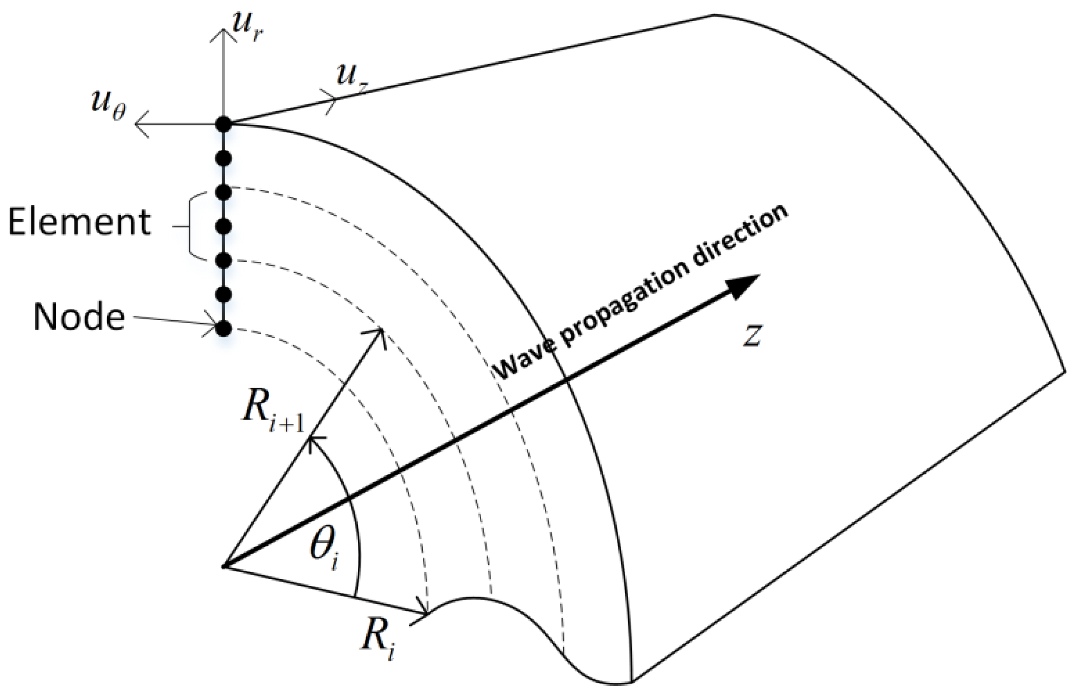
The mathematical framework for an infinitely long, axisymmetric waveguide immersed in a vacuum is represented using the semi-analytical method. The method follows a cylindrical coordinate system with the cross-section laying in the r–z plane, as shown in Figure 1. The SAFE model represents fluctuation along the wave propagation axis z with wavenumber (k), and frequency (ꞷ). As the trigonometric function component is introduced in advance in the interpolation function, the displacement interpolation is performed only in the radial direction of the section. In this case, the element form is reduced from 2D to 1D, and the quadratic element has three nodes, as shown in Figure 1.
The displacement field function in the finite element format can be written as,
where the interpolation function matrix is,
For time–harmonic wave , a linear viscoelastic material model can be simulated by including the imaginary component in the material stiffness matrix [6],
where contains the energy storage modulus and consists of the energy dissipation modulus. In the hysteresis model, the imaginary part of the stiffness matrix is independent of frequency ,
where is the elastic stiffness tensor and is the viscous tensor. For the high-strength steel strands, the hysteresis model is usually used for simulation analysis. In Equation (4), the material stiffness matrix has 21 independent variables as a general form, which can simulate non-isotropic materials. The energy velocity and attenuation factor are more reasonable indicators of the wave characteristics of a damped waveguide medium. The energy velocity is defined as the counterpart of the group velocity in a purely elastic material and represents the energy propagation velocity in the waveguide medium. The attenuation factor represents the attenuation of each modal wave with the propagation distance. The energy velocity and attenuation characteristics are obtained by further extracting the data in the curve for analysis. If the material of the waveguide medium is considered to be viscoelastic, then it is necessary to change the material stiffness matrix to the corresponding complex stiffness matrix. For high-strength steel wire, attenuation factors of longitudinal body wave, , and transverse body wave, , respectively.
3. Effect of Initial Tensile Stress on Wave Propagation Characteristics
In this paper, high-strength steel wire with a diameter of 5 mm is considered for numerical investigations, and the material characteristics are tabulated in Table 1. The friction between the steel wires and the secondary stress caused by temperature and other factors have a strong practical significance in the study of the influence of stress on the wave propagation characteristics.
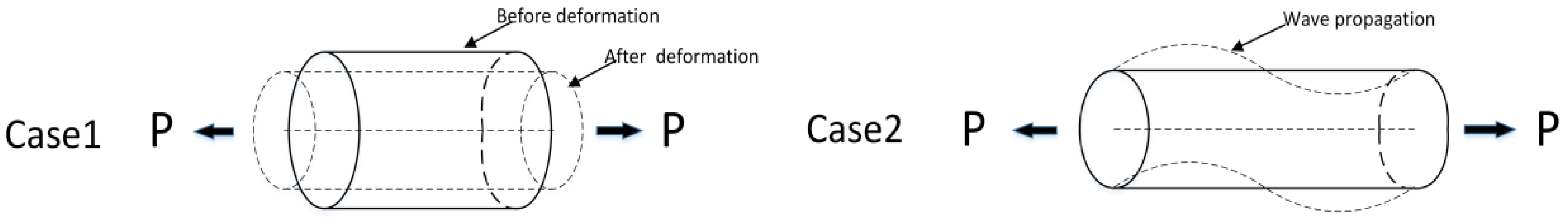
The virtual work equations need to be established under two equilibrium states to consider the initial stress effect caused due to fluctuations in the elastic body. The first equilibrium state is that a single wire is subjected to axial tension to achieve static balance, and the corresponding static virtual work equation is,
where represents the initial stress field, which is caused by the axial tensile force, represents the applied load field, precisely the axial force in this case study. Moreover, and represent the virtual displacement and virtual strain, respectively, and they should satisfy the boundary conditions of displacement. The second equilibrium state is the dynamic balance of the guided wave as it propagates through the wire. At this time, the virtual work equation considers not only the inertial force factor but also the contribution of the initial stress field. The virtual work equation is as follows,
where represents the stress field generated by guided wave propagation; and represent the virtual strain and virtual displacement, respectively, where is the complete form of the virtual strain, which is . Figure 2 shows the two equilibrium states for establishing the virtual work equation. Therefore, the virtual work term in the axial initial stress field can be transformed into,
Finally, the semi-analytical frequency equation containing the initial stress matrix has [10],
where is the overall initial stress matrix. It can be seen that is the modification of the matrix.
3.1. Numerical Investigation
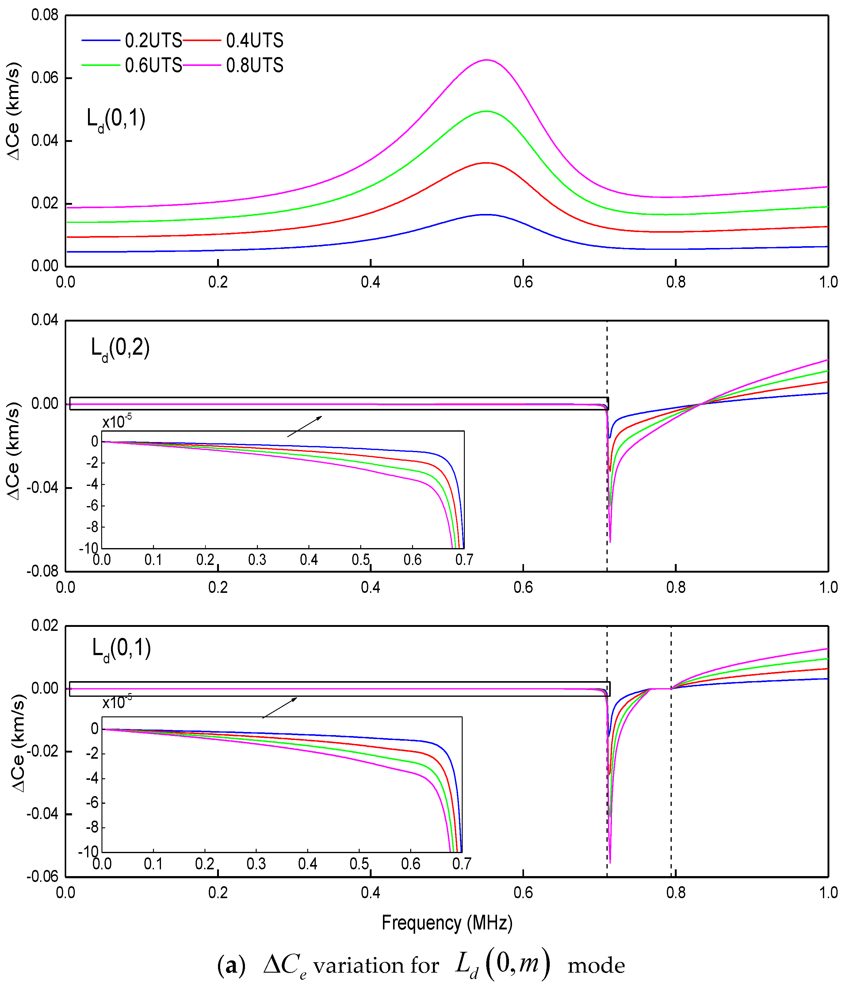
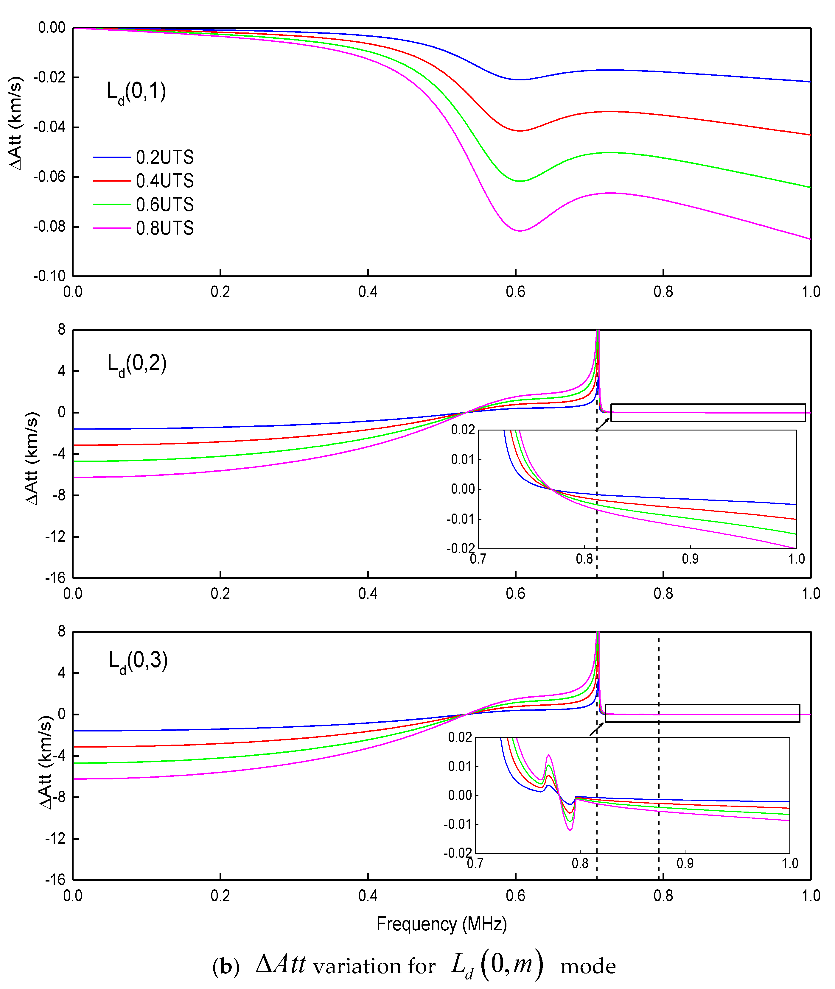
In this section, the influence of tensile stress on energy velocity and attenuation is discussed. The ultimate tensile stress (UTS) of high-strength steel wire used in actual engineering is 1860 MPa, and the stress on the cable is generally 0.3~0.4 of the UTS. The comparative analysis of initial stress uses 0.0, 0.2, 0.4, 0.6, and 0.8 times the UTS values to explore the effect of stress on wave propagation characteristics. Since the torsional mode occupies a small part of the AE signal, only the longitudinal and bending wave modes are considered in this section. Figure 3a,b show the variation curves of energy velocities, , and attenuation, of, mode with frequency under the four initial tensile stress conditions.
High initial tensile stress can increase the stiffness of the system (in this case, increase the corresponding stiffness of the matrix), thereby increasing the energy velocity and reducing the attenuation. However, this effect only occurs in relatively high-frequency bands, which are generally higher than the cut-off frequency of each mode. For modes in the low-frequency region that contain high attenuation factors, even if the attenuation factor decreases with increasing tensile stress, the amount of energy velocity change may still be negative, such as 0–0.5 MHz in mode. The sharply concave part of the energy change curve or the sharply protruding peak of the attenuation factor represents the transition area in the energy curve. In this area, the energy velocity rapidly increases from the frequency axis to a specific maximum value. Fortunately, from a practical point of view, only those quasi-propagating modal initial tension forces have a clear and reasonable effect on them, which is worth noting. From Figure 3, it can be seen that the impact of initial tensile stress on energy velocity or attenuation is monotonous; i.e., they continue to increase or decrease as the stress level increases. This trend is still approximately linear because, at each frequency point, the interval of the target change amount under the four stress levels is the same, but this linear factor itself changes with frequency.
The primary issue comprised in AE monitoring is the attenuation of the acoustic signals. As it is carrying less energy, it gets mixed with noise, which in turn causes significant difficulties in subsequent signal processing steps. The signal caused by friction and collision between the steel wires will also be continuously introduced into the system during the wave propagation so that the AE signal may be contaminated. Therefore, the selection of modes applicable to AE monitoring should follow the two points of low attenuation and small external surface vibration. The only possibility is longitudinal wave modes as they have simple modal forms and a limited number relative to bending modes.
4. Conclusions
In this paper, the author presents the development and results of a method to calculate the characteristics of guided waves in a wire, with intended applications in AE monitoring. The work includes the possibility of material damping in the waveguide and also of pre-stress. By considering structural damping, the wavenumber at any point on the curve is complex, and modal curves are separated in space, which makes them easy to distinguish. The initial tensile stress can be calculated and analyzed by the semi-analytical stiffness matrix in the form of a geometric stiffness matrix. In practical scenarios, there is a considerable initial tensile stress in the steel wire of the bridge cable. Without considering the effects of other stress fields and other deformation, the 0.2, 0.4, 0.6, and 0.8 times UTS values are analyzed for the effect of initial stress conditions. It can be found that for propagating waves above the cut-off frequency, the initial tensile stress can slightly increase the energy velocity and reduce the attenuation factor. This effect is linear at each frequency point, but this law is not evident for evanescent waves. The longitudinal wave modes considered in the high-frequency region are suitable for AE monitoring as it has low attenuation factor and relatively small external surface vibration. The proposed formulation for analyzing the prestressed field in the viscoelastic waveguide showed a possible way for guided wave-based non-destructive evaluation and health monitoring applications. This study can help to select suitable modes with low attenuation characteristics that may be useful for monitoring AE events.
Funding
This research received no external funding.
Conflicts of Interest
The author declares no conflict of interest.
References
- Saravanan, T.J.; Gopalakrishnan, N.; Rao, N.P. Damage detection in structural element through propagating waves using radially weighted and factored RMS. Measurement 2015, 73, 520–538. [Google Scholar] [CrossRef]
- Saravanan, T.J.; Gopalakrishnan, N.; Rao, N.P. Detection of damage through coupled axial-flexural wave interactions in a sagged rod using spectral finite element method. J. Vib. Control 2017, 23, 3345–3364. [Google Scholar] [CrossRef]
- Kumar, K.V.; Saravanan, T.J.; Sreekala, R.; Gopalakrishnan, N.; Mini, K.M. Structural damage detection through longitudinal wave propagation using spectral finite element method. Geomech. Eng. 2017, 12, 161–183. [Google Scholar] [CrossRef]
- Saravanan, T.J.; Gopalakrishnan, N.; Rao, N.P. Experiments on coupled axial-flexural wave propagation in a sagged rod with structural discontinuity using piezoelectric transducers. J. Vib. Control 2018, 24, 2717–2731. [Google Scholar] [CrossRef]
- Saravanan, T.J. Investigation of guided wave dispersion characteristics for fundamental modes in an axisymmetric cylindrical waveguide using rooting strategy approach. Mech. Adv. Mater. Struct. 2020, 1–11. [Google Scholar] [CrossRef]
- Saravanan, T.J. Convergence study on ultrasonic guided wave propagation modes in an axisymmetric cylindrical waveguide. Mech. Adv. Mater. Struct. 2020, 1–18. [Google Scholar] [CrossRef]
- Galán, J.M.; Abascal, R. Numerical simulation of Lamb wave scattering in semi-infinite plates. Int. J. Numer. Methods Eng. 2002, 53, 1145–1173. [Google Scholar] [CrossRef]
- Marzani, A.; Viola, E.; Bartoli, I.; Di Scalea, F.L.; Rizzo, P. A semi-analytical finite element formulation for modeling stress wave propagation in axisymmetric damped waveguides. J. Sound Vib. 2008, 318, 488–505. [Google Scholar] [CrossRef]
- Mu, J.; Rose, J.L. Guided wave propagation and mode differentiation in hollow cylinders with viscoelastic coatings. J. Acoust. Soc. Am. 2008, 124, 866–874. [Google Scholar] [CrossRef] [PubMed]
- Gavrić, L. Computation of propagative waves in free rail using a finite element technique. J. Sound Vib. 1995, 185, 531–543. [Google Scholar] [CrossRef]
- Chen, F.; Wilcox, P.D. The effect of load on guided wave propagation. Ultrasonics 2007, 47, 111–122. [Google Scholar] [CrossRef] [PubMed]
- Loveday, P.W. Semi-analytical finite element analysis of elastic waveguides subjected to axial loads. Ultrasonics 2009, 49, 298–300. [Google Scholar] [CrossRef] [PubMed]
- Mazzotti, M.; Marzani, A.; Bartoli, I.; Viola, E. Guided waves dispersion analysis for prestressed viscoelastic waveguides by means of the SAFE method. Int. J. Solids Struct. 2012, 49, 2359–2372. [Google Scholar] [CrossRef]
- Saravanan, T.J. Non-destructive testing mechanism for pre-stressed steel wire using acoustic emission monitoring. Materials 2020, 13, 5029. [Google Scholar] [CrossRef] [PubMed]
Figure 1.
Representation of the semi-analytical finite element (SAFE) model and its nodal degree of freedom.
Figure 1.
Representation of the semi-analytical finite element (SAFE) model and its nodal degree of freedom.

Figure 2.
The equilibrium state of the virtual work.

Figure 3.
Influence of initial tensile stress on energy velocity and attenuation.


Table 1.
Material characteristics of high strength steel wire.
| Young’s Modulus, E (MPa) | Density, ρ (kg/m3) | Poisson’s Ration, ν | Diameter, d (mm) | Longitudinal Wave Velocity, CL (m/s) | Shear Wave Velocity, CS (m/s) |
|---|---|---|---|---|---|
| 2×10⁵ | 7850 | 0.3 | 5 | 5856.4 | 3130.4 |
Publisher’s Note: MDPI stays neutral with regard to jurisdictional claims in published maps and institutional affiliations. |
© 2020 by the author. Licensee MDPI, Basel, Switzerland. This article is an open access article distributed under the terms and conditions of the Creative Commons Attribution (CC BY) license (https://creativecommons.org/licenses/by/4.0/).
Share and Cite
MDPI and ACS Style
Thiyagarajan, J.S. Analysis of Preload Effect in the Axisymmetric Damped Steel Wire Using Ultrasonic Guided Wave Monitoring. Eng. Proc. 2020, 2, 1. https://doi.org/10.3390/ecsa-7-08162
AMA Style
Thiyagarajan JS. Analysis of Preload Effect in the Axisymmetric Damped Steel Wire Using Ultrasonic Guided Wave Monitoring. Engineering Proceedings. 2020; 2(1):1. https://doi.org/10.3390/ecsa-7-08162
Chicago/Turabian StyleThiyagarajan, Jothi Saravanan. 2020. "Analysis of Preload Effect in the Axisymmetric Damped Steel Wire Using Ultrasonic Guided Wave Monitoring" Engineering Proceedings 2, no. 1: 1. https://doi.org/10.3390/ecsa-7-08162