Article

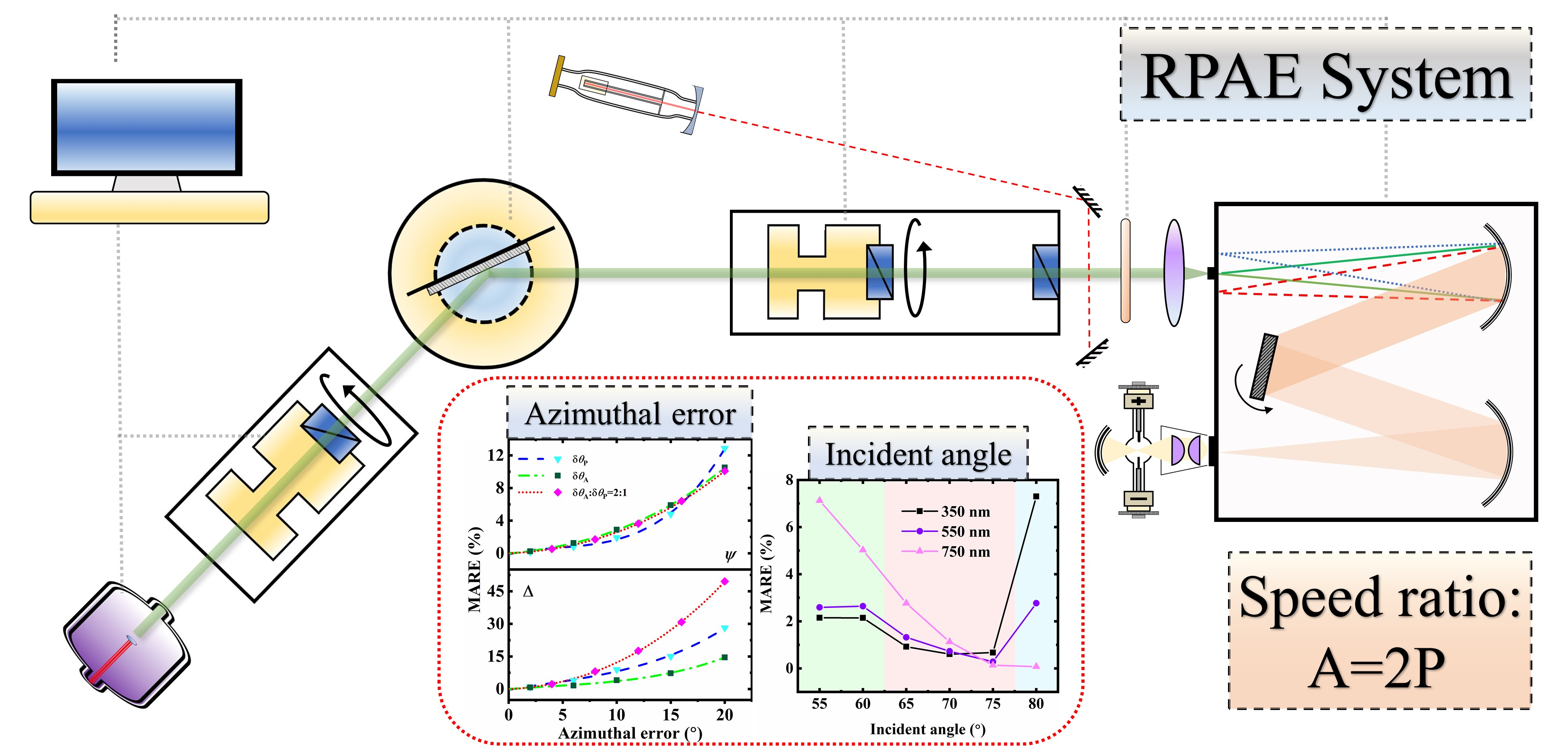
Method for Analyzing the Measurement Error with Respect to Azimuth and Incident Angle for the Rotating Polarizer Analyzer Ellipsometer

1
Department of Optical Science and Engineering, Key Laboratory of Micro and Nano Photonic Structures, Ministry of Education, Shanghai Engineering Research Center of Ultra-Precision Optical Manufacturing, Fudan University, Shanghai 200433, China
2
Department of Physics, Quantum Photonic Science Research Center and RINS, Hanyang University, Seoul 04763, Korea
*
Authors to whom correspondence should be addressed.
Crystals 2021, 11(4), 349; https://doi.org/10.3390/cryst11040349
Submission received: 2 March 2021 / Revised: 22 March 2021 / Accepted: 25 March 2021 / Published: 29 March 2021

Abstract

:
We proposed a method to study the effects of azimuth and the incident angle on the accuracy and stability of rotating polarizer analyzer ellipsometer (RPAE) with bulk Au. The dielectric function was obtained at various incident angles in a range of 55°–80° and analyzed with the spectrum of the principal angle. The initial orientations of rotating polarizing elements were deviated by a series of angles to act as the azimuthal errors in various modes. The spectroscopic measurements were performed in a wavelength range of 300–800 nm with an interval of 10 nm. The repeatedly-measured ellipsometric parameters and determined dielectric constants were recorded monochromatically at wavelengths of 350, 550, and 750 nm. The mean absolute relative error was employed to evaluate quantitatively the performance of instrument. Apart from the RPAE, the experimental error analysis implemented in this work is also applicable to other rotating element ellipsometers.

Graphical Abstract

1. Introduction

The rotating element ellipsometer, after continuous development in many different configurations and applications, is widely employed as a primary technique in scientific research and industry [1,2,3,4,5,6,7,8,9]. The typical rotating element ellipsometer system comprises various types: the rotating polarizer ellipsometer (RPE) [10,11], the rotating analyzer ellipsometer (RAE) [12,13,14], and the rotating polarizer analyzer ellipsometer (RPAE).
The RPAE, which allows the polarizer and the analyzer to rotate in different angular velocities simultaneously, was firstly proposed by Azzam [15]. Intensive efforts have been devoted to RPAE from different aspects in past decades [16,17,18,19,20]. A self-established RPAE was constructed and presented in 1987 [16], with the polarizer and the analyzer rotating synchronously at an angular velocity ratio of 1:2. The system is superior in the elimination of DC signal error and phase-shift correction. Additionally, it provided two methods for the determination of ellipsometric parameters to realize the self-consistency of the data. Subsequently, the instrument was improved in 1994 [18], which enabled a fully variable incident angle by micro-stepping techniques, and employed a fixed polarizer to eliminate the effect of residual polarization from a light source.
The system and random errors have been extensively studied as an important topic in the development of ellipsometry. The accuracy and precision of ellipsometry can be effectively improved by performing error analysis and reduction. The analyses and corrections of errors, caused by the imperfect compensator and birefringence in window, were performed by McCrackin in 1970 [21]. Aspnes systematically presented the measurement and the correction of the first-order errors [22] and the uncertainties of ellipsometric parameters [23,24]. Azzam and Bashara investigated the errors from imperfect components, cell-window birefringence, and incorrect azimuth angles [25], and performed systematic error analysis on the RAE [26]. The errors in ellipsometry have been extensively analyzed in various aspects, such as the beam deviation [27], birefringence of window [28,29], incident angle [30], azimuthal errors, and residual ellipticity [31,32,33]. Moreover, the systematic error analyses on different configurations have been reported, including the RAE [34], PRPSE [35], multichannel ellipsometer [36], and the Mueller matrix ellipsometer [37,38].
Although the aforementioned error analyses are conditionally applicable to the RPAE, the error investigations specifically for this type of ellipsometer are still limited. The noise effect of Fourier coefficients on the RPAE with the same configuration as in [18] was analyzed by simulation [39]. In our previous work, the systematic error reduction, induced by the analytical discrete Fourier transform, was proposed theoretically and tested experimentally [40]. Apart from the effect from the Fourier transformation, the experimental performance affected by the systematic error is worth studying further.
In this work, a method to study the error analysis on the incident angle and azimuth was presented experimentally for the self-established RPAE with bulk Au. Both spectroscopic and monochromatic repeated measurements were carried out at various incident angles. The dielectric constants were determined from the measured ellipsometric parameters to study the accuracy and stability, which were evaluated according to the differences and dispersion degrees of experimental data compared with the reference values, respectively. The initial azimuths of polarizing elements were adjusted rotationally by groups of certain angles to study the effect of azimuthal errors in three modes. The performance of RPAE was evaluated quantitatively with the mean absolute relative error (MARE). The error analysis method proposed in this work is also useful for spectroscopic ellipsometry, including temperature-dependent properties of thin polymer films and metal nanoparticles [41,42,43,44].

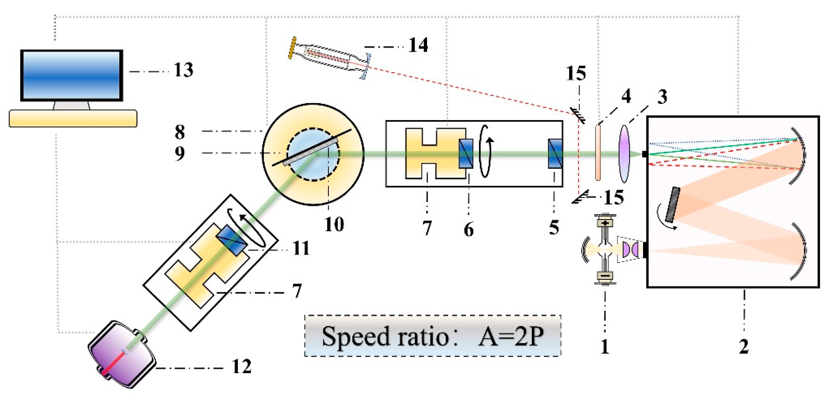
2. Materials and Methods

Figure 1 schematically illustrates the configuration of the RPAE system. A monochromator containing a rotatable grating for the wavelength scan was employed to disperse the light from the source. The monochromatic light from the exit slit passed through a collimator lens, a fixed polarizer, and a rotating polarizer in sequence before incidence on the sample. Subsequently, the reflected light went through a rotating analyzer and entered a detector for data acquisition. The acquired analog signal was converted to a digital one for data processing. The initial azimuths of polarizing elements were set along the direction perpendicular to the incident plane. The angular velocity of the rotating analyzer was controlled to be twice that of the rotating polarizer. The optical system was aligned and calibrated precisely by a low-power He-Ne laser to realize a continuously variable incident angle in a range of 45°–90°, with a computer-controlled resolution of 0.001° or a visual resolution of 0.005° [18]. The spectroscopic measurement was performed routinely through a wavelength scan in a spectral range of 300–800 nm with an interval of 10 nm. Au was selected as the test material for the low penetration depth in the visible range with a great optical stability in the atmospheric environment.
The light intensity at the detector for RPAE is expressed as:
I ( A ) = I 0 + I 1 cos A + I 2 cos 2 A + I 3 cos 3 A + I 4 cos 4 A ,
where A represents the azimuth of analyzer and I0I4 are coefficients of one direct and four harmonic components, which are obtained by applying the discrete Fourier analysis as
I k = 2 n i = 1 n I ( A i ) cos ( k A i )       k = 1 , 2 , 3 , 4 ,
where Ai is the ith analyzer azimuth in the measurement period. Accordingly, the ellipsometric parameters are determined by [16,17,18]:
tan ψ 1 = [ 2 ( I 1 + I 3 2 I 2 ) I 1 + I 3 ] 1 / 2 , cos Δ 1 = I 1 3 I 3 [ 2 ( I 1 + I 3 ) ( I 1 + I 3 2 I 2 ) ] 1 / 2 ,
and
tan ψ 2 = [ 9 ( I 1 + I 3 2 I 2 ) 2 ( 2 I 1 + I 2 + 4 I 4 ) ] 1 / 2 , cos Δ 2 = 3 ( I 1 + I 3 ) 4 ( I 2 + 4 I 4 ) [ 8 ( I 1 + I 3 ) ( I 1 + I 3 2 I 2 ) ] 1 / 2 .
The two sets of solutions are self-consistent to quantitatively verify the reliability of the results without other instruments. We prefer to use Equation (3) in the experiment, since the value of I4 is the smallest in Equation (1). For bulk material measured at an incident angle of θ in the atmosphere, the dielectric function is determined with the well-known equation:
ε ˜ = sin 2 θ [ 1 + t a n 2 θ ( 1 tan ψ e i Δ 1 + tan ψ e i Δ ) 2 ] .
The accuracy and stability are evaluated by the MARE. The value of the MARE is given by:
MARE = 1 n i = 1 n | x i measured x i reference x i reference | × 100 % ,
where n represents the amount of data.

3. Results

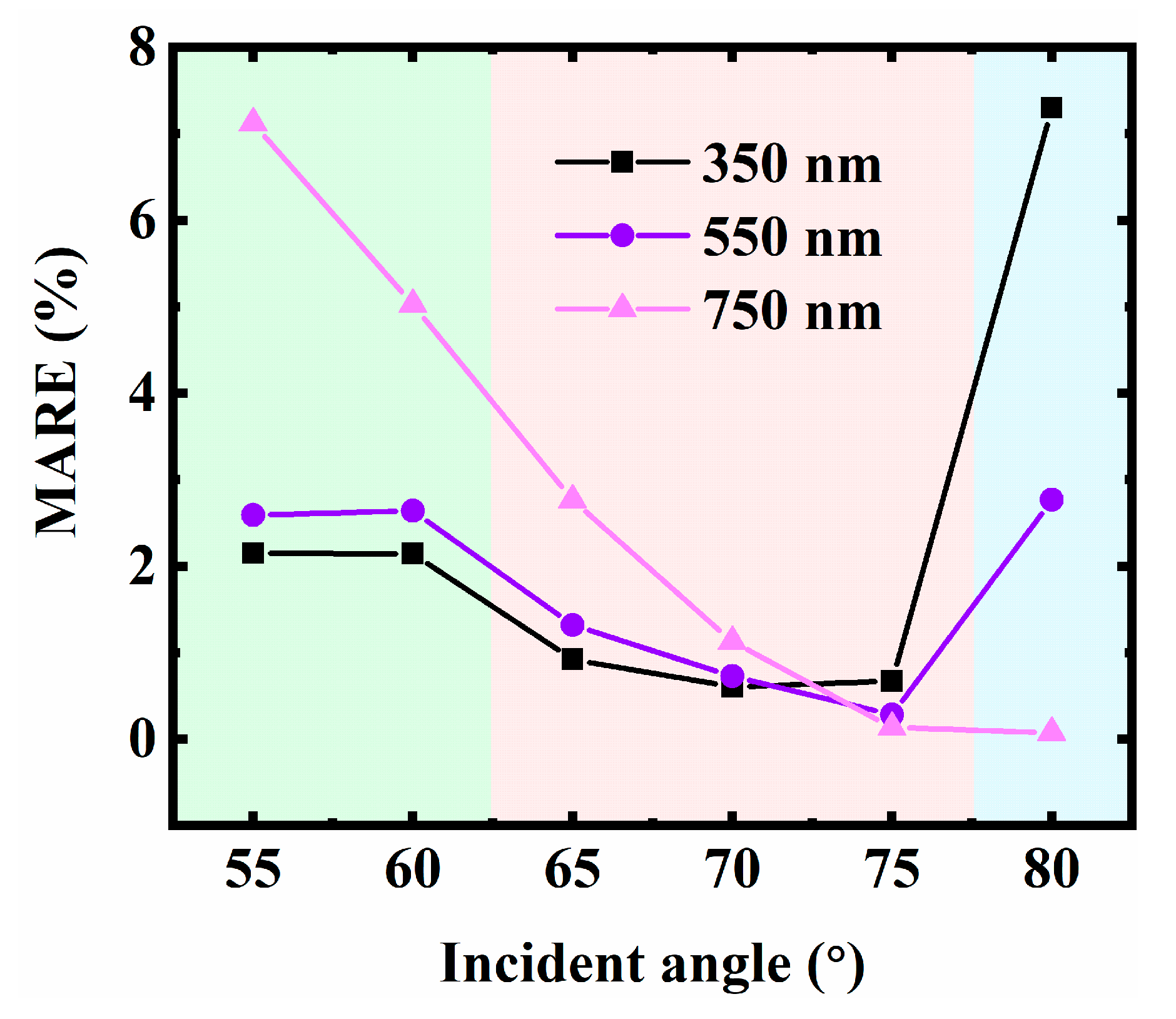
3.1. Incident Angle and Principal Angle

The incident angle satisfying the condition of Δ = 90° is defined as the principal angle [45]. The error was proved theoretically to be reduced to obtain the highest precision in determining the optical constants when measured at the principal angle [17]. The spectrum of the principal angle for the Au sample was both theoretically and experimentally investigated in our previous work [46]. In this section, the ellipsometric measurements were performed by the RPAE at a series of incident angles in a range of 55° to 80°, with an interval of 5°, to evaluate the accuracy and stability.

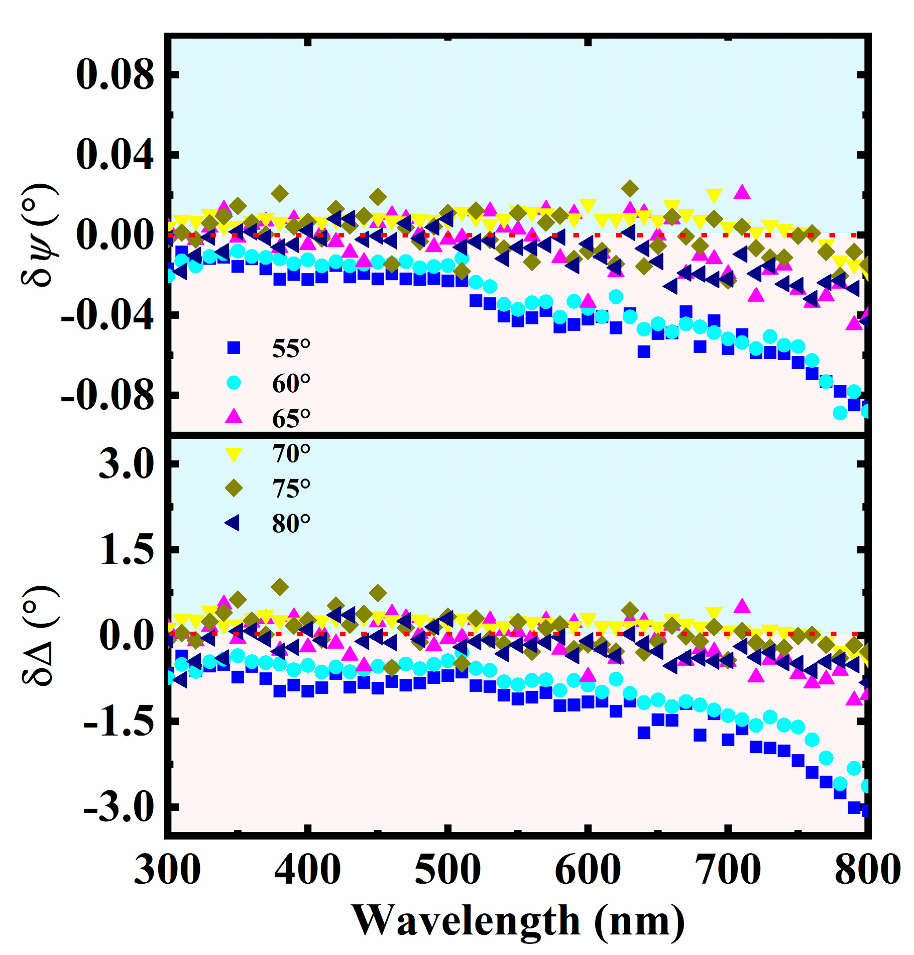
3.1.1. Spectroscopic Measurement

The dielectric function spectra of the Au sample at various incident angles (Figure 2) were determined from the measured ellipsometric parameters with Equation (5). The spectra showed great agreement in most of the wavelength range. On the other hand, discrepancies were observed obviously in some regions, especially in the long-wavelength range. The reference dielectric function was obtained by applying the Model dielectric function [47] and Drude model [48] to the spectra of various incident angles. Accordingly, the spectrum of the principal angle was calculated with the method presented in [46], as shown in Figure 3.
The RPAE gave two solutions to determine the values of ψ and Δ with Equations (3) and (4). Theoretically, the results extracted by the two solutions were expected to be equal. The differences between the two results, defined as δψ = ψ1ψ2 and δΔ = Δ1 – Δ2, are used generally to evaluate the reliability of measurement. The values of δψ and δΔ in the spectral range are exhibited in Figure 4. For the incident angles in 65°–80°, the differences between the two sets varied around 0 in the spectral range, which implied good credibility for measurement. Meanwhile, the differences of 55° and 60° were relatively large, especially in the long wavelength range. As indicated in Figure 3, the principal angle increased significantly in the long wavelength range, reaching approximately 80°. Consequently, larger measurement errors occurred at incident angles of 55° and 60° away from the principal angle, leading to the significant discrepancy between the two solutions.
The MARE values of the dielectric function at different incident angles are given in Table 1. The results demonstrate that the accuracy was dependent on the wavelength and corresponding principal angle. The measured results at 65°, 70°, and 75° turned out to be more accurate than those measured at 55°, 60°, and 80° in a wavelength range of 300–800 nm, which was consistent with the analysis based on the spectrum of the principal angle.

3.1.2. Monochromatic Measurement

The monochromatic measurements at different incident angles were tested by performing 100 repeated measurements at a single wavelength of 350 nm. The real and imaginary parts of the reference dielectric constant at 350 nm were determined as ε1 = −1.09 and ε2 = 5.2, respectively. The principal angle of the Au sample at 350 nm was calculated to be 69.43°. Figure 5a,b display the distribution of the measured ellipsometric parameters and determined dielectric constants, respectively, at six incident angles. The data amount at each incident angle in an accurate region (relative error of ±2%, illustrated in Figure 5) is counted and listed in Table 2. The statistical values demonstrated that the results at 70°, 65°, and 75° had more accurate data compared with the others, which was consistent with the theoretical analysis of the principal angle.
The repeated measurement procedure was performed subsequently on two other wavelengths of 550 and 750 nm at different incident angles. The corresponding MAREs of the real part of the dielectric constant with varying incident angles were calculated at three wavelength points, as indicated in Figure 6. The principal angles of the Au sample at 350, 550, and 750 nm were determined to be 69.43°, 70.53°, and 78.01°, respectively. The MARE versus incident angle implies that the measurement exhibited higher accuracy and smaller error with the incident angle close to the principal angle. For example, the MARE at 750 nm decreased significantly with the increasing incident angle, which was attributed to the corresponding principal angle of 78.01°. At incident angles of 65°, 70°, and 75°, the MAREs turned out to be relatively small at all three wavelengths in Figure 6, representing the short, middle, and long wavelength parts in the spectral range. Accordingly, the results indicated that these three incident angles enabled accurate measurement for the Au sample and some other typical metals.

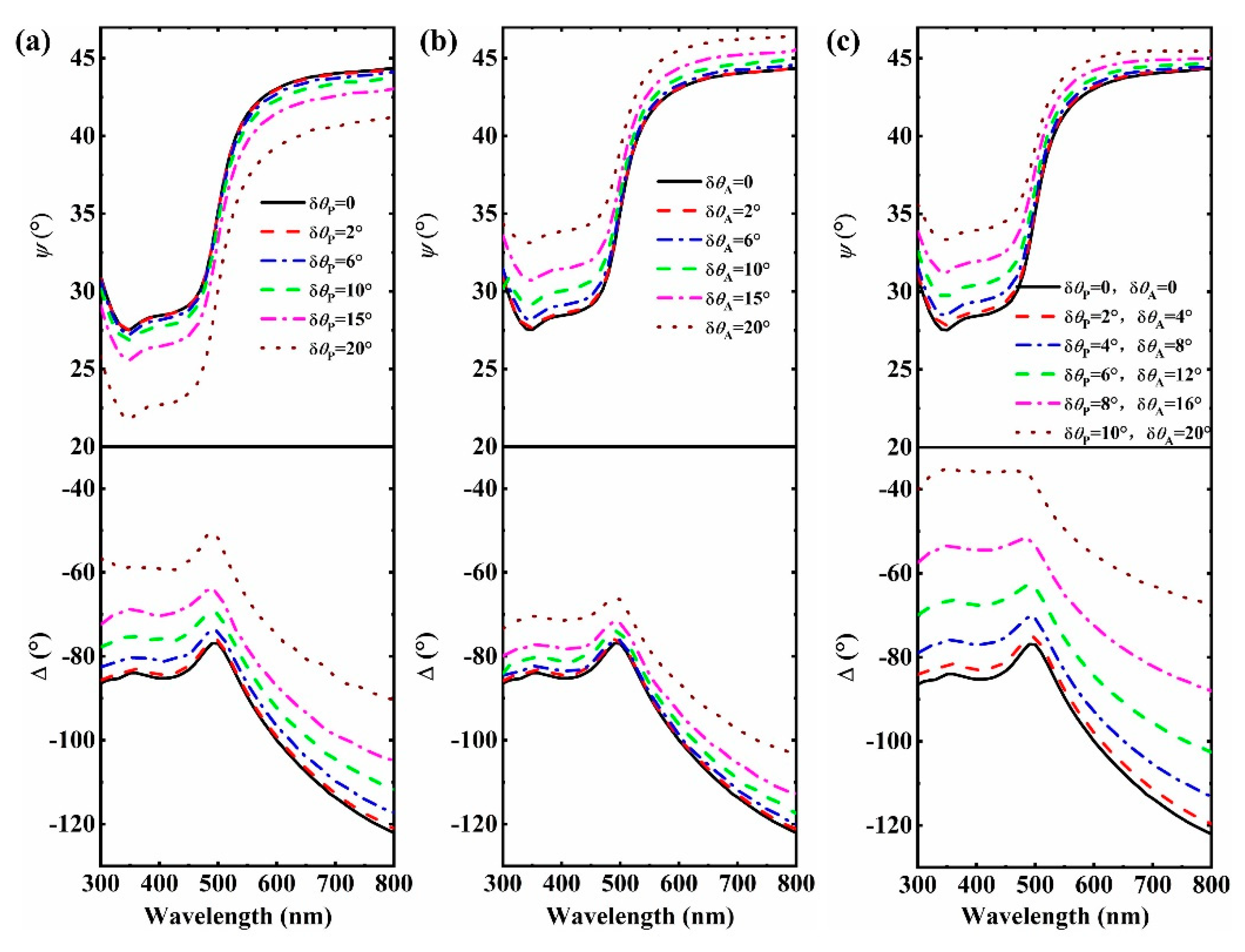
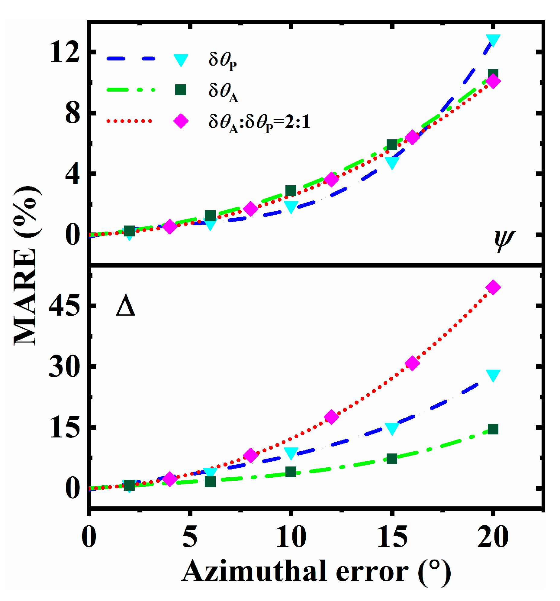
3.2. Azimuthal Error

In the rotating element ellipsometers, the measurement is fundamentally based on the detection of different polarization states, which is usually realized with the rotating elements. Consequently, the azimuthal error of the polarizing element significantly affects the performance of the instrument. In this subsection, we experimentally investigated the effect of the azimuthal error on the accuracy and stability of the results. The initial azimuths of the polarizer and analyzer were adjusted rotationally by a certain angle from the s-axis to act as the azimuthal errors, represented as δθP and δθA, respectively.

3.2.1. Theoretical Analysis

For the measurement with the azimuthal error δ, assuming that the condition A = 2P is still satisfied, the expression of light intensity in Equation (1) is modified as:
I δ ( A ) = I 0 + I 1 cos ( A + δ ) + I 2 cos 2 ( A + δ ) + I 3 cos 3 ( A + δ ) + I 4 cos 4 ( A + δ ) .
Compared with Equation (2), the four harmonic components are determined as:
I k δ = 2 cos k δ n i = 1 n I δ ( A i ) cos ( k A i ) = sec k δ I k       k = 1 , 2 , 3 , 4 .
Consequently, the ellipsometric parameters obtained in experiment are given as:
tan ψ δ 1 = [ 2 ( I 1 sec δ + I 3 sec 3 δ 2 I 2 sec 2 δ ) I 1 sec δ + I 3 sec 3 δ ] 1 / 2 , cos Δ δ 1 = I 1 sec δ 3 I 3 sec 3 δ [ 2 ( I 1 sec δ + I 3 sec 3 δ ) ( I 1 sec δ + I 3 sec 3 δ 2 I 2 sec 2 δ ) ] 1 / 2 ,
and
tan ψ δ 2 = [ 9 ( I 1 sec δ + I 3 sec 3 δ 2 I 2 sec 2 δ ) 2 ( 2 I 1 sec δ + I 2 sec 2 δ + 4 I 4 sec 4 δ ) ] 1 / 2 , cos Δ δ 2 = 3 ( I 1 sec δ + I 3 sec 3 δ ) 4 ( I 2 sec 2 δ + 4 I 4 sec 4 δ ) [ 8 ( I 1 sec δ + I 3 sec 3 δ ) ( I 1 sec δ + I 3 sec 3 δ 2 I 2 sec 2 δ ) ] 1 / 2 .

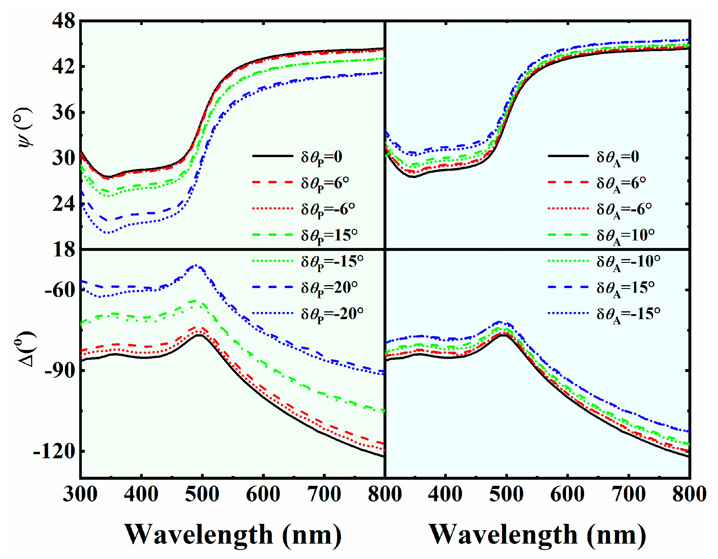
3.2.2. Experimental Results

Firstly, the ellipsometric parameters of the Au sample were measured by the RPAE at an incident angle of 70° in a wavelength range of 300–800 nm, with δθP varying from 0–20°, as shown in Figure 7a. The spectra of ψ and Δ demonstrated that the measured results deviated significantly from the standard spectra with the increasing of the azimuthal error of the polarizer. Similarly, the ellipsometric measurements were performed with δθA varying from 0–20°, as shown in Figure 7b. The spectra of ψ deviated differently compared with those of δθP. Since the analyzer and polarizer rotated at an angular velocity ratio of 1:2 in measurement, the values of δθA and δθP were set at a group of angles with the same ratio. The value of δθA varied from 0–20°, compared with that of δθP in a range of 0–10°. Hence, the azimuth of the analyzer was always twice that of the polarizer during rotation. The same procedure was repeated to get the spectra of ψ and Δ (Figure 7c).
The MAREs of ψ and Δ were calculated and fitted into curves by applying the polynomial fitting method for three azimuthal error modes, as displayed in Figure 8. The comparison revealed the effect of the azimuthal error on the accuracy quantitatively. For the MARE of ψ, the three curves behaved similarly with small azimuthal errors, while the value increased significantly with a large value of δθP. As for Δ, the value increased slightly for the curve of δθA, while rapidly for that of δθP and δθPθA = 1:2. Therefore, the azimuthal error of the polarizer was indicated to more seriously affect the accuracy of the RPAE.
The polarizing elements were rotated in the opposite direction with the same absolute values of azimuthal errors to study the directional dependence on accuracy. The spectra of ψ and Δ, measured for a series of the same absolute values, showed a high consistency for both ±δθP and ±δθA, as observed in Figure 9. Consequently, the accuracy of the RPAE was found to be less dependent on the direction of the azimuthal error in terms of the acquired spectra.

4. Conclusions

We presented a method to implement the experimental error analysis of azimuth and the incident angle specifically for the RPAE in this work. The dielectric functions of bulk Au were determined from the measured ψ and Δ at incident angles in a range of 55°–80°, with an interval of 5°, to study the effect on the instrument. The results acquired at an incident angle close to the principal angle were observed to exhibit higher accuracy and better stability, according to the discrepancies between the two solutions, and the values of the MARE. The azimuthal error analysis was performed experimentally with the initial orientations of polarizing elements deviating from the zero azimuth. The fitting curves of the MARE versus azimuthal error suggest that δθP more seriously affects the accuracy of the RPAE. The demonstrated error analysis reveals the relationship between the acquired data and experimental conditions, which gives access to achieving accurate and reliable measurement by using the RPAE, and is easily generalized to other rotating element ellipsometers.

Author Contributions

Conceptualization, H.T. and Y.Z.; methodology, H.T.; validation, Y.S., Y.C., and H.Z.; formal analysis, H.T. and Y.S.; investigation, Y.C. and H.Z.; data curation, Y.Z., Y.L. and L.C.; writing—original draft preparation, H.T.; writing—review and editing, Y.Z., R.Z., S.W., J.L., Y.L. and L.C.; supervision, Y.Z. and L.C.; project administration, Y.Z. and L.C.; funding acquisition, Y.Z. and L.C. All authors have read and agreed to the published version of the manuscript.

Funding

This research was funded by the National Natural Science Foundation of China, grant number 61775042 11674062 and the Fudan University CIOMP Joint Fund, grant number FC2017-003.

Institutional Review Board Statement

Not applicable.

Informed Consent Statement

Not applicable.

Data Availability Statement

Not applicable.

Acknowledgments

We would like to express our sincere appreciations to the anonymous referees for valuable suggestions and corrections.

Conflicts of Interest

The authors declare no conflict of interest.

References

  1. Azzam, R.M.A.; Bashara, N.M. Ellipsometry and Polarized Light; North-Holland: Amsterdam, The Netherlands, 1977. [Google Scholar]
  2. Hauge, P.S. Recent developments in instrumentation in ellipsometry. Surf. Sci. 1980, 96, 108–140. [Google Scholar] [CrossRef]
  3. Woollam, J.A.; Snyder, P.G.; Rost, M.C. Variable angle spectroscopic ellipsometry—A non-destructive characterization technique for ultrathin and multilayer materials. Thin Solid Film. 1988, 166, 317–323. [Google Scholar] [CrossRef]
  4. Collins, R.W. Automatic rotating element ellipsometers: Calibration, operation, and real-time applications. Rev. Sci. Instrum. 1990, 61, 2029–2062. [Google Scholar] [CrossRef]
  5. Aspnes, D.E. Expanding horizons: New developments in ellipsometry and polarimetry. Thin Solid Film. 2004, 455–456, 3–13. [Google Scholar] [CrossRef]
  6. Tompkins, H.G.; Irene, E.A. Handbook of Ellipsometry; William Andrew: New York, NY, USA, 2005. [Google Scholar]
  7. Fujiwara, H. Spectroscopic Ellipsometry: Principles and Applications; John Wiley & Sons: Tokyo, Japan, 2007. [Google Scholar]
  8. Aspnes, D.E. Spectroscopic ellipsometry—Past, present, and future. Thin Solid Film. 2014, 571, 334–344. [Google Scholar] [CrossRef]
  9. Azzam, R.M.A. Polarization, thin-film optics, ellipsometry, and polarimetry: Retrospective. J. Vac. Sci. Technol. B 2019, 37, 060802. [Google Scholar] [CrossRef]
  10. Cahan, B.D.; Spanier, R.F. A high speed precision automatic ellipsometer. Surf. Sci. 1969, 16, 166–176. [Google Scholar] [CrossRef]
  11. Stobie, R.W.; Rao, B.; Dignam, M.J. Analysis of a novel ellipsometric technique with special advantages for infrared spectroscopy. J. Opt. Soc. Am. 1975, 65, 25–28. [Google Scholar] [CrossRef]
  12. Aspnes, D.E. Fourier transform detection system for rotating-analyzer ellipsometers. Opt. Commun. 1973, 8, 222–225. [Google Scholar] [CrossRef]
  13. Aspnes, D.E.; Studna, A.A. High Precision Scanning Ellipsometer. Appl. Opt. 1975, 14, 220. [Google Scholar] [CrossRef]
  14. Schubert, M.; Rheinlander, B.; Woollam, J.A.; Johs, B.; Herzinger, C.M. Extension of rotating-analyzer ellipsometry to generalized ellipsometry: Determination of the dielectric function tensor from uniaxial TiO2. J. Opt. Soc. Am. 1996, 13, 875. [Google Scholar] [CrossRef]
  15. Azzam, R.M.A. A simple Fourier photopolarimeter with rotating polarizer and analyzer for measuring Jones and Mueller matrices. Opt. Commun. 1978, 25, 137–140. [Google Scholar] [CrossRef]
  16. Chen, L.Y.; Lynch, D.W. Scanning ellipsometer by rotating polarizer and analyzer. Appl. Opt. 1987, 26, 5221–5228. [Google Scholar] [CrossRef]
  17. Chen, L.Y.; Feng, X.W.; Su, Y.; Ma, H.Z.; Qian, Y.H. Improved rotating analyzer-polarizer type of scanning ellipsometer. Thin Solid Films 1993, 234, 385–389. [Google Scholar] [CrossRef]
  18. Chen, L.Y.; Feng, X.W.; Su, Y.; Ma, H.Z.; Qian, Y.H. Design of a scanning ellipsometer by synchronous rotation of the polarizer and analyzer. Appl. Opt. 1994, 33, 1299–1305. [Google Scholar] [CrossRef]
  19. El-Agez, T.M.; El Tayyan, A.A.; Taya, S.A. Rotating polarizer-analyzer scanning ellipsometer. Thin Solid Film. 2010, 518, 5610–5614. [Google Scholar] [CrossRef]
  20. El-Agez, T.M.; Taya, S.A. Development and construction of rotating polarizer analyzer ellipsometer. Opt. Laser. Eng. 2011, 49, 507–513. [Google Scholar] [CrossRef]
  21. Mccrackin, F.L. Analyses and corrections of instrumental errors in ellipsometry. J. Opt. Soc. Am. 1970, 60, 57–63. [Google Scholar] [CrossRef]
  22. Aspnes, D.E. Measurement and correction of first-order errors in ellipsometry. J. Opt. Soc. Am. 1971, 61, 1077–1085. [Google Scholar] [CrossRef]
  23. Aspnes, D.E. Optimizing precision of rotating-analyzer ellipsometers. J. Opt. Soc. Am. 1974, 64, 639–646. [Google Scholar] [CrossRef]
  24. Aspnes, D.E. Optimizing precision of rotating-analyzer and rotating-compensator-ellipsometers. J. Opt. Soc. Am. 2004, 21, 403–410. [Google Scholar] [CrossRef] [PubMed]
  25. Azzam, R.M.A.; Bashara, N.M. Unified analysis of ellipsometry errors due to imperfect components, cell-window birefringence, and incorrect azimuth angles. J. Opt. Soc. Am. 1971, 61, 600–607. [Google Scholar] [CrossRef]
  26. Azzam, R.M.A.; Bashara, N.M. Analysis of systematic errors in rotating-analyzer ellipsometers. J. Opt. Soc. Am. 1974, 64, 1459–1469. [Google Scholar] [CrossRef]
  27. Zeidler, J.R.; Kohles, R.B.; Bashara, N.M. Beam Deviation Errors in Ellipsometric Measurements; an Analysis. Appl. Opt. 1974, 13, 1938–1945. [Google Scholar] [CrossRef] [Green Version]
  28. Jin, L.; Kasuga, S.; Kondoh, E. General window correction method for ellipsometry measurements. Opt. Express 2014, 22, 27811–27820. [Google Scholar] [CrossRef]
  29. Nissim, N.; Eliezer, S.; Bakshi, L.; Moreno, D.; Perelmutter, L. In situ correction of windows’ linear birefringence in ellipsometry measurements. Opt. Commun. 2009, 282, 3414–3420. [Google Scholar] [CrossRef]
  30. Humlicek, J. Sensitivity extrema in multiple-angle ellipsometry. J. Opt. Soc. Am. A 1985, 2, 713–722.31. [Google Scholar] [CrossRef]
  31. Kleim, R.; Kuntzler, L.; El Ghemmaz, A. Systematic errors in rotating-compensator ellipsometry. J. Opt. Soc. Am. A 1994, 11, 2550–2559. [Google Scholar] [CrossRef]
  32. Bertucci, S.; Pawlowski, A.; Nicolas, N.; Johann, L.; El Ghemmaz, A.; Stein, N.; Kleim, R. Systematic errors in fixed polarizer, rotating polarizer, sample, fixed analyzer spectroscopic ellipsometry. Thin Solid Films 1998, 313–314, 73–78. [Google Scholar] [CrossRef]
  33. Chao, Y.F.; Lee, K.Y.; Lin, Y.D. Analytical solutions of the azimuthal deviation of a polarizer and an analyzer by polarizer-sample-analyzer ellipsometry. Appl. Opt. 2006, 45, 3935–3939. [Google Scholar] [CrossRef]
  34. Nijs, J.M.M.; Silfhout, A.V. Systematic and random errors in rotating-analyzer, ellipsometry. J. Opt. Soc. Am. A 1988, 5, 773–781. [Google Scholar] [CrossRef]
  35. En Naciri, A.; Broch, L.; Johann, L.; Kleim, R. Fixed polarizer, rotating-polarizer and fixed analyzer spectroscopic ellipsometer: Accurate calibration method, effect of errors and testing. Thin Solid Films 2002, 406, 103–112. [Google Scholar] [CrossRef]
  36. Nguyen, N.V.; Pudliner, B.S.; An, I.; Collins, R.W. Error correction for calibration and data reduction in rotating-polarizer ellipsometry applications to a novel multichannel ellipsometer. J. Opt. Soc. Am. A 1991, 8, 919–931. [Google Scholar] [CrossRef]
  37. Nee, S. Error analysis for Mueller matrix measurement. J. Opt. Soc. Am. A 2003, 20, 1651–1657. [Google Scholar] [CrossRef]
  38. Broch, L.; Naciri, A.E.; Johann, L. Systematic errors for a Mueller matrix dual rotating compensator ellipsometer. Opt. Express 2008, 16, 8814–8824. [Google Scholar] [CrossRef] [PubMed]
  39. El-Agez, T.M.; Taya, S.A. An extensive theoretical analysis of the 1:2 ratio rotating polarizer–analyzer Fourier ellipsometer. Phys. Scr. 2011, 83, 25701. [Google Scholar] [CrossRef]
  40. Mao, P.; Zheng, Y.; Cai, Q.; Zhang, D.; Zhang, R.; Zhao, H.; Chen, L. Approach to Error Analysis and Reduction for Rotating-Polarizer-Analyzer Ellipsometer. J. Phys. Soc. Jpn. 2012, 81, 124003. [Google Scholar] [CrossRef]
  41. Hajduk, B.; Bednarski, H.; Trzebicka, B. Temperature-Dependent Spectroscopic Ellipsometry of Thin Polymer Films. J. Phys. Chem. B 2020, 124, 3229–3251. [Google Scholar] [CrossRef] [PubMed]
  42. Nosidlak, N.; Jaglarz, J.; Danel, A. Ellipsometric studies for thin polymer layers of organic photovoltaic cells. J. Vac. Sci. Technol. B 2019, 37, 062402. [Google Scholar] [CrossRef]
  43. Hajduk, B.; Bednarski, H.; Jarząbek, B.; Nitschke, P.; Janeczek, H. Phase diagram of P3HT:PC70BM thin films based on variable-temperature spectroscopic ellipsometry. Polym. Test 2020, 84, 106383. [Google Scholar] [CrossRef]
  44. Jarząbek, B.; Nitschke, P.; Hajduk, B.; Domański, M.; Bednarski, H. In situ thermo-optical studies of polymer:fullerene blend films. Polym. Test 2020, 88, 106573. [Google Scholar] [CrossRef]
  45. Azzam, R.M.A. Contours of constant principal angle and constant principal azimuth in the complex epsilon-plane. J. Opt. Soc. Am. A 1981, 71, 1523–1528. [Google Scholar] [CrossRef] [Green Version]
  46. Zhu, X.; Zhao, H.; Zhang, R.; Ma, Y.; Liu, Z.; Li, J.; Shen, Z.; Wang, S.; Chen, L. Analytical study of the principal angle used in optical experiments. Appl. Opt. 2002, 41, 2592–2595. [Google Scholar] [CrossRef] [PubMed]
  47. Aspnes, D.E.; Kinsbron, E.; Bacon, D.D. Optical-properties of Au: Sample effects. Phys. Rev. B 1980, 21, 3290–3299. [Google Scholar] [CrossRef]
  48. Takeuchi, K.; Adachi, S. Optical properties of β-Sn films. J. Appl. Phys. 2009, 105, 073520. [Google Scholar] [CrossRef]
Figure 1. Schematic configuration of the RPAE optical system. (1) The continuous light source; (2) the monochromator consisting of two spherical mirrors and a rotatable plane grating; (3) light-collimating lens; (4) rotatable filters; (5) fixed polarizer; (6) rotating polarizer; (7) stepping motors; (8) rotating stage; (9) sample rotator; (10) sample; (11) rotating analyzer; (12) photomultiplier; (13) computer to control the monochromator, stepping motors, filters, rotating table, sample stage, and the photomultiplier; (14) laser used for alignment; and (15) mirrors to guide the laser beam for alignment.
Crystals 11 00349 g001
Figure 2. Dielectric functions of bulk Au determined at six incident angles.
Crystals 11 00349 g002
Figure 3. Spectrum of the principal angle for bulk Au.
Crystals 11 00349 g003
Figure 4. Discrepancies of the two sets of ellipsometric parameters at six incident angles in a spectral range.
Crystals 11 00349 g004
Figure 5. Distribution of the 100 (a) repeatedly-measured ellipsometric parameters, and (b) determined dielectric constants for six incident angles at a wavelength of 350 nm.
Crystals 11 00349 g005
Figure 6. Values of MARE versus the incident angle at three wavelengths.
Crystals 11 00349 g006
Figure 7. Measured ellipsometric parameters with various azimuthal errors of (a) the polarizer, (b) analyzer, and (c) both at a ratio of 1:2.
Crystals 11 00349 g007
Figure 8. Experimental data (points) and fitted curves (lines) of MAREs versus azimuthal errors (for δθAθP = 2:1, the horizontal axis represents δθA).
Crystals 11 00349 g008
Figure 9. Ellipsometric parameters measured with azimuthal errors of the same absolute values in the opposite direction.
Crystals 11 00349 g009
Table 1. MARE values of the dielectric functions at different incident angles.
Incident Angle (°)556065707580
MARE-ε1 (%)6.254.901.780.101.701.94
MARE-ε2 (%)9.125.453.81.394.194.19
Table 2. Amounts of data points in an accurate region shown in Figure 5 in the 100 repeated measurements for different incident angles at a wavelength of 350 nm.
Incident Angle (°)556065707580
Amount of data points302796100688
Publisher’s Note: MDPI stays neutral with regard to jurisdictional claims in published maps and institutional affiliations.

