The Resolution in X-ray Crystallography and Single-Particle Cryogenic Electron Microscopy


1
Faculty of Science and Engineering, University of Groningen, Nijenborgh 4, 9747 AG Groningen, The Netherlands
2
Groningen Biomolecular Sciences & Biotechnology Institute (GBB), University of Groningen, Nijenborgh 4, 9747 AG Groningen, The Netherlands
3
Moscow Institute of Physics and Technology, 141701 Dolgoprudny, Russia
*
Author to whom correspondence should be addressed.
Crystals 2020, 10(7), 580; https://doi.org/10.3390/cryst10070580
Submission received: 13 May 2020
/
Revised: 25 June 2020
/
Accepted: 3 July 2020
/
Published: 5 July 2020
(This article belongs to the Special Issue A 10 Years Journey: Chemical, Physical, and Biological Properties and Applications of Crystals)
Abstract
:X-ray crystallography and single-particle analysis cryogenic electron microscopy are essential techniques for uncovering the three-dimensional structures of biological macromolecules. Both techniques rely on the Fourier transform to calculate experimental maps. However, one of the crucial parameters, resolution, is rather broadly defined. Here, the methods to determine the resolution in X-ray crystallography and single-particle analysis are summarized. In X-ray crystallography, it is becoming increasingly more common to include reflections discarded previously by traditionally used standards, allowing for the inclusion of incomplete and anisotropic reflections into the refinement process. In general, the resolution is the smallest lattice spacing given by Bragg’s law for a particular set of X-ray diffraction intensities; however, typically the resolution is truncated by the user during the data processing based on certain parameters and later it is used during refinement. However, at which resolution to perform such a truncation is not always clear and this makes it very confusing for the novices entering the structural biology field. Furthermore, it is argued that the effective resolution should be also reported as it is a more descriptive measure accounting for anisotropy and incompleteness of the data. In single particle cryo-EM, the situation is not much better, as multiple ways exist to determine the resolution, such as Fourier shell correlation, spectral signal-to-noise ratio and the Fourier neighbor correlation. The most widely accepted is the Fourier shell correlation using a threshold of 0.143 to define the resolution (so-called “gold-standard”), although it is still debated whether this is the correct threshold. Besides, the resolution obtained from the Fourier shell correlation is an estimate of varying resolution across the density map. In reality, the interpretability of the map is more important than the numerical value of the resolution.
1. Introduction
“Seeing is believing” is at the heart of structural biology. Both X-ray crystallography and single-particle cryogenic electron microscopy (cryo-EM) have become essential for uncovering the three-dimensional (3D) structures of biological macromolecules. With both techniques it is possible to obtain the structures with high resolution with the current absolute record of 0.48 Å for crystallography [1] and near atomic resolution of 1.54 Å achieved by single particle analysis [2] and ~1 Å resolution with micro-ED. Resolution in nuclear magnetic resonance (NMR) is an entirely different concept and more of a “philosophical” question, and will not be discussed here. Atomic resolution allows one to distinguish individual atoms and has its certain benefits, for refinement and model building [3]. Atomic resolution is not a strictly defined term though. It is regularly thought that a resolution of 1.2 Å or higher is an atomic resolution, better known as “Sheldrick’s criterion” [4]. Near-atomic resolution usually describes maps which are of a resolution of 2 Å or better but is not strictly defined. The terms “atomic” and “near-atomic” are occasionally misused describing maps not close to their respective resolutions [5]. Furthermore, to many non-structural biologists it may be very confusing how the resolution is defined in X-ray crystallography or cryo-EM.
Resolution in X-ray crystallography and cryo-EM is different from the usual interpretation of resolution as generally accepted in light microscopy. In the light microscopy field, the resolution was first defined by Lord Rayleigh as the smallest distance at which two point sources can be still distinguished [6]. At this distance, the maximum of one point source coincides with the first minimum of the other. However, the definition of Lord Rayleigh is not applicable in X-ray crystallography and cryo-EM, because both techniques make use of Fourier space to determine the resolution of data. Fourier space and the nature of the experimental data make the resolution determination less clear and can confuse anyone without experience with these techniques. The recent technological progress in the structural biology and the enormous effort of software developers to make their software user-friendly have brought many new users sometimes without deep understanding of techniques. The aim of this mini-review is to give an introductory overview on how the resolution of data is determined in X-ray crystallography and single particle cryo-EM.
2. X-ray Crystallography
X-ray crystallography is the oldest and most productive field of structural biology (~145.00 entries in the protein data bank), where crystals of the protein of interest are irradiated with X-ray photons. The crystal diffracts the X-ray beam into discrete diffraction spots, also called reflections. The amplitudes are measured during the experiment and the missing phases are obtained via Molecular Replacement (MR) [7,8], single- or multiple-wavelength anomalous dispersion (SAD or MAD) [9,10], multiple isomorphous replacement (MIR) [11] or ab initio [12,13]. The farther away the reflections are from the center of the detector, the higher resolution information they contain. However, with increasing resolution, the signal decreases. At a certain distance from the center of the detector, the signal will be too weak and this, in principle, will be the resolution limit of the dataset. There are numerous statistics for the quality of the data including, but not limited to, R-factors, signal-to-noise ratio () and completeness. These statistical measures are also used to truncate the data and thus to decide which reflections are not of sufficient quality for the consequent map calculation, followed by model building and refinement. This, in a way, also sets the resolution limit of the dataset. However, it was shown that in many cases inclusion of weak incomplete high-resolution data still improves the quality of the model. The standards derived in the past are often too strict and underestimate the information in the excluded data [14,15,16]. This ignited a debate about the usefulness of information contained in the weak high-resolution reflections and the general consensus now is to use all the available data with a few considerations (see below) [17,18,19]. It also showed a flaw in the resolution normally reported in Table 1 or in the Protein Data Bank (PDB) entries. The current recommendation is to diligently report if incomplete anisotropic data were used.
2.1. Resolution Cutoff
“Where to truncate my data?” (Also known as resolution cut-off) - Is one of the most popular questions asked when people start learning protein crystallography. Old textbooks recommend to keep only the strongest reflections and truncate the data at the threshold where the signal-to-noise ratio equals 2 for the highest resolution shell; gradually this requirement was relaxed to about 1.5 and sometimes even to 1.0 but recently even this threshold has been questioned [14,15,16]. The classic indicators used to determine where to truncate the data are the signal-to-noise ratio <> and the , which was first introduced as [20]. Nowadays, and are used interchangeably; however, historically was used for symmetry-related reflections, whereas was introduced to evaluate the difference between different datasets. The truncation deemed necessary as at low signal-to-noise ratio it would be hard to differentiate the signal from the stochastic noise, hence bringing the risk that noise is mixed with the signal and that it will be incorporated into the calculated electron density map. Therefore, the data is truncated and with signal-to-noise threshold of 2 all reflections with a signal less than twice the intensity of the estimated noise will be discarded as a safety measure irrespective whether they contain useful information or not. The is a statistic for the precision of the measurements of each unique reflection (i.e., it is a measure of agreement among multiple measurements of the same reflection):
where is the intensity of the reflections, is the average intensity, and they are summed over the measured reflections. Many reflections are measured more than once as they are symmetry-related. indicates how much measurements of the same reflection differ in intensity from the average intensity of that reflection. It was postulated that large shows that the measurements of the same reflection are not similar (error prone), hence the data should be truncated at the resolution shell where is over an arbitrary limit (typically 40–60%).
However, is inherently flawed [21], as it is dependent on multiplicity (also called redundancy) and its value increases with more measurements of the same reflection, even though the precision of the measurement goes up. Diederichs and Karplus (1997) introduced a multiplicity-independent R-factor named [21]:
where each reflection is corrected with a factor of , where denotes the multiplicity of the reflection. When corrected, the outcome stays constant with varying multiplicity, while would increase or decrease. Therefore, indicates the real precision of the measurement, independent of the multiplicity of the reflection. Unfortunately, many users keep resisting to report simply because it shows a higher (but more realistic) value than and many erroneously think that the lower value the better.
() and are used to evaluate individual (unmerged) reflections and for merged (i.e., averaged) reflections another R-factor was introduced [22], namely (precision-indicating merging R-factor)
The or were often used in tandem with the signal-to-noise ratio as a resolution cut-off. Commonly, if the rose above or <> dropped below 2, the reflections would be considered not good enough to be included in the map calculation and would be discarded. It seemed to be a good way to determine where to truncate the data; however, several scientists have shown that the inclusion into refinement of weak high-resolution data, with an <> below 1 and an well over 100%, might be beneficial [14,15,16].
Karplus and Diederichs proposed a new statistic as a quality indicator to define the resolution limit of a dataset [14]. They introduced a Pearson’s correlation coefficient, . Correlation coefficients are widely used in cryo-EM (discussed below) and in X-ray crystallography for anomalous phasing. Furthermore, as pointed out by Evans and Murshudov, correlation coefficients report the degree of linear dependence between data and are less dependent on the distribution of the data [15], and therefore they are better indicators. is based on the random division of the complete set of reflections in two equal parts and calculating the correlation between the intensity estimates of the two subsets (i.e., how well one half of the data predicts the other half). A value of 1 indicates a perfect correlation, whereas 0 indicates no correlation at all. At low resolution (where the strongest reflections are measured), the correlation is around 1 and it goes down with the higher resolution approaching zero at the highest resolution (where the weakest reflections are measured). , by definition cannot be used though to estimate the quality of the data after merging, thus Karplus and Diederichs also introduced ,
provides an estimate of the that would be obtained between the final merged dataset and the unknown true values that they are representing [14]. Importantly, it allows comparing data and model quality by calculating and as the CC between (square of the calculated structure factor) and (square of the observed structure factor), respectively.
It has been shown by many that using this novel statistic for resolution truncation is very beneficial for getting better resolved maps, improved refinement and improved models [23,24] and it allowed for better merging of datasets from different crystals [25,26]. If classical criteria for resolution truncation were considered in those cases the numbers would be shocking—with values up to 1000% and signal-to-noise ratio of 0.3. However, as elaborated by Karplus & Diederichs, or both approach infinity with increasing resolution, thus rendering them useless as quality indicators.
Nevertheless, there is a problem with as it does not provide one rock solid threshold, e.g., that data below shall be discarded. In reality depending on data quality, the useful range of lies somewhere between 0.1 and 0.5 [18,27]. To determine the exact value of for the particular dataset the paired refinement procedure is recommended [14]. In brief, the quality of a model is evaluated against the dataset truncated at different resolution cut-offs and if any additional batch of high-resolution reflections does not contribute positively in the model quality, those reflections are discarded. The easiest way to perform it, is to run it via PDB Redo server [28], which is also useful to correct modelling errors.
2.2. Resolution of the Dataset
First and foremost, we need to understand how the resolution is defined in X-ray crystallography. What is normally referred to as resolution is the nominal resolution (). This is defined by the smallest distance (typically measured in Å) between crystal lattice planes that is resolved in the diffraction pattern, i.e., if this number is lower, the resolution is higher and vice versa. Generally resolution of 0.5–1 Å is called subatomic (or ultra-high), 1–1.5 Å (1.2 Å according to Sheldrick [4]) –atomic, 1.5–2 Å –high, 2–3 Å –medium, 3–5 Å –low, and worse than 5 Å very low resolution. In a way, is dictated by the resolution cut-off (truncation) which was applied during the data processing. However, this is very subjective (see above). Furthermore, is not accommodating the data completeness or anisotropy, but it merely reflects the highest resolution shells used regardless of the completeness and anisotropy of the dataset. The nominal resolution is therefore much more an indicator of where someone has truncated their data and says nothing about its quality.
As an alternative, the optical resolution () can be used [29,30]. It should not be confused though with the optical resolution in light microscopy, where it can be defined by the minimum distance r at which the points on a specimen can be distinguished as individual entities. In X-ray crystallography Vaguine et al. (1999) defined the optical resolution as the expected minimum distance between two resolved peaks (which shapes are fitted by a Gaussian) in the electron-density map, i.e., it shows the smallest distance at which two peaks can still be seen as separate, if one had a perfect electron-density map with all the exact phases [30].
where is the standard deviation of the Gaussian function fitted to the Patterson origin peak and is the standard deviation of the Gaussian function fitted to the origin peak of the spherical interference function, representing the Fourier transform of a sphere with radius .
The optical resolution is always higher than the nominal resolution of a dataset. However, an increase in the nominal resolution gives a smaller increase in the optical resolution [18]. According to Vaguine et al. (1999), equals twice the standard deviation of a fit to Gaussian; however, later Urzhemtseva et al. (2013) noticed that such an approach is sub-optimal as it demonstrated inconsistent results [29], e.g., the of an incomplete dataset is higher than that of the complete dataset. Urzhemtseva et al. (2013) suggested an improved method to determine the , without a need to perform a fit to Gaussian, by calculating as the minimum distance at which two C atoms could still be resolved with a typical B-factor [29] (also called atomic displacement parameter (ADP), which describes the displacement of an atom—i.e., the atoms cannot be considered as immobile point scatterers). The B-factor are generally estimated from the Wilson plot [31]. Unfortunately, the optical resolution does suffer from the same flaws as the nominal resolution does: it does not reflect the completeness or the anisotropy of the dataset. Moreover, the is calculated using the Wilson plot which describes the typical B-factor of a scatterer at a given resolution. However, in this way the real B-factors at high resolution are systematically underestimated. Nevertheless, it can be used to compare different datasets, especially in combination with other statistical indicators, such as the and the , to evaluate the dataset.
To account for the completeness of the data, Weiss suggested yet another resolution, termed effective resolution () and it has a semi-empirical correlation with the completeness of the dataset [32]. It was defined as the nominal resolution multiplied with the cube root of the completeness of the dataset:
In such a form only accounts for the completeness but not the anisotropy of the data. To overcome this limitation a more complete derivation was suggested [29,33]. In short, can be defined via comparison of the calculated minimum distance for point scatterers with the theoretical values for the complete dataset [29]. Furthermore, the anisotropy of the dataset can be characterized by calculating in different directions. The ratio of the highest effective resolution () and the lowest effective resolution () defines the anisotropy , where
The effective resolution coincides with if the dataset is complete and does not have anisotropy.
3. Electron Microscopy
Cryo-EM has recently become a very popular structural biology technique due to the several technological advances, such as direct electron detectors [34,35,36], new generation of microscopes, more advanced and used-friendly software [37,38], etc. The amount of structures solved with cryo-EM is steadily rising as well as their resolution, which allowed this technique to shake the partial “blobology” label. With the increasing resolution though the same old problem re-emerged—what is actually the resolution in cryo-EM? Currently, multiple resolution criteria are in use, with Fourier shell correlation (FSC) being by far the most used one [39,40]. Even though FSC is widely accepted by the scientific community, a never-ending discussion continues about a threshold at which the resolution should be defined. Alternatives for the FSC, such as Spectral Signal-to-Noise Ratio (SSNR) [41,42,43] and Fourier Neighbor Correlation (FNC) [44] exist but are not common. Each method has its own limitations and is based on different assumptions, which makes it difficult to reach a consensus. For an extensive statistical description and behavior of the most commonly used resolution measures, see the recent review by Sorzano et al. (2017) [45]. To add to the complexity, the resolution determined as a single numerical value is, in a way, an average of the density map; however, in cryo-EM the resolution varies within a map itself, thus it is essential to calculate the local resolution of the density map as well.
3.1. Fourier Shell Correlation
The Fourier shell correlation was first introduced for 2D reconstructions as the Fourier Ring Correlation (FRC) [39,40] and was later extended to 3D reconstructions [46]. The basis of FSC is the comparison of independently calculated maps from half the dataset and determining where these maps stop correlating
The correlation is calculated over each shell () in the Fourier transform, where and are the structure factors of half map 1 and 2, respectively, at position r within Fourier shell and where * indicates the complex conjugate.
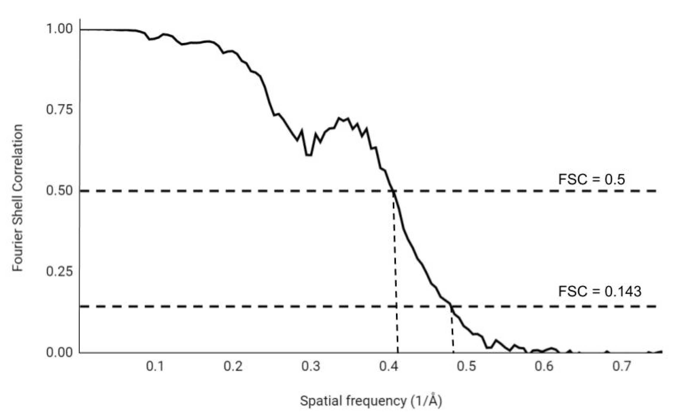
At the start of refinement, the complete dataset is split in half and a 3D map is calculated from each half. Each half map is then refined individually and treated separately without any interactions between the two half maps to guarantee independence. The correlation of these two half maps is calculated, from low spatial frequency (low resolution) to high spatial frequency (high-resolution). The FSC curve is normalized between 1, for highly correlating maps, and 0, for non-correlating maps. The signal of the protein contribution decreases with increasing spatial frequency, thus the map will be less and less defined by the protein and more by the stochastic noise at higher spatial frequencies. As a result of that, the individual half maps correlate less and the correlation drops (Figure 1).
The discussion concerning the resolution limit of EM maps is actually about the threshold value where two half maps do not correlate anymore, in other words, the spatial frequency at which two half maps are considered to be not correlated (this immediately indicates that this is subjective) defines the resolution of the map. Initially a value of 0.5 was chosen as the threshold at which half maps were considered as not correlated. This is still one of the most often used (and the most conservative) thresholds for the FSC curve and it corresponds to an SNRC of 1 (SNRC being the signal-to-noise ratio in the particular Fourier shell) [45]. However, this threshold value of 0.5 is said to underestimate the resolution [47,48], as during this procedure the data are split randomly in halves. This means that during refinement there are half less particles than when the complete dataset were used. Having fewer particles makes the dataset noisier, as there are fewer particles to average with. To overcome this problem, a new processing method (named the “gold standard” method) was introduced [47,48], which currently is the most accepted and widely used in the EM community. The resolution determined by the gold standard method is often the one reported for structures in the PDB or the Electron Microscopy Data Bank (EMDB). In this gold standard method the models derived from each half dataset are refined independently opposed to having two maps and a single model. This decreases unintended correlation of the compared maps and lessens the effect of data overfitting but does not eliminate it entirely [48,49]. The suggested threshold value of 0.143 originates from a 0.5 value of correlation of the complete dataset and an unknown perfect map of the macromolecule. The threshold of 0.5 for the estimated correlation was chosen for two main reasons. First, the estimated correlation can be written out as a function of the phase error. This is equivalent to an X-ray crystallographic measure of the accuracy of the phases, the figure of merit (FOM). The FOM is commonly used in X-ray crystallography as an indication if the map is interpretable enough to build a structure in it. A value of 0.5 corresponds to a phase error of which is considered as interpretable enough to build a structure into the density map [50]. Second, the FSC can be related to the real space correlation coefficient (R), a measure of similarity between two density maps. When there are no amplitude errors present, the real space correlation coefficient R corresponds to the estimated correlation of the complete dataset and the unknown perfect map. Using this, one can predict if the addition of a Fourier shell will have a positive effect on the correlation of the map and the perfect map and thus improve the map itself with 0.5 being the threshold [50].
An alternative threshold used is the sigma () criterion. It uses the standard deviation, where denotes the number samples in the Fourier shell with radius r. The FSC of the density maps is then compared to an FSC based entirely on noise. The obtained value ranges from 1 to 5, meaning that the correlation needs to be bigger than the signal of pure noise by 1 to 5 times. Even though the criterion has not been widely accepted, some advocate for its use because it is not a fixed value threshold but it depends on the number of samples in the Fourier shells [51,52]. A fixed value is one of the main critiques of the 0.143 and 0.5 thresholds, as they do not account for the amount of Fourier components in the shells or symmetry of the structure [51]. This makes its outcome less reproducible than a varying threshold.
To overcome this issue, Van Heel and Schatz introduced a new modified version of the criterion [51,52]. It is a bit-based information criterion imposing a variable threshold depending whether there is still enough information in the signal to improve the calculated density map. This threshold should correct a presumed wrong assumption of the FSC calculation and make the resolution calculation independent of the number of voxels (a 3D pixel in Fourier space) in each Fourier shell and symmetry of the structure. For the full details and statistical basis of the bit-based information criterion, the reader is referred to Van Heel & Schatz (2005) [51]. A 1/2-bit threshold is proposed to define the resolution of the density map. This is not a fixed value threshold as it varies with symmetry, box size, and voxels in the Fourier shell. However, as identified by Sorzano et al. (2017) [45], this an almost arbitrarily chosen threshold that corresponds to an SNR of 0.4142, while a 1-bit threshold corresponds to an SNR of 1.
Apart from the discussion on the correct threshold, the FSC curve anyway is not an ideal tool to determine the resolution. First, the complete dataset is processed before the splitting it in equal halves. This means that the two half datasets are not fully independent and can carry some biases increasing the estimated resolution [53]. Secondly, the resolution estimate is not affected by isotropic filtering of the complete dataset [42,45]. When a low-pass filter is applied, meaning only the low spatial frequencies are left, the FSC curve stays the same and thus the same resolution estimate is obtained. Furthermore, the values of the resolution that the aforementioned criteria produce seem not differ greatly. In some specific cases, some criteria may function better than others but there is most likely no perfect criterion. The behavior of the complete FSC curve is a better indicator of the quality of the reconstruction instead of an exact coordinate where it crosses the threshold value: the curve should stay as high as possible before it passes the chosen threshold value.
3.2. Spectral Signal-To-Noise Ratio
The spectral signal-to-noise ratio was first introduced for 2D reconstructions in 1987 [41] and, similar to the FSC, was sequentially extended for 3D reconstructions [42,43]. It is one of the easiest methods conceptually, as a similar criterion is also used in X-ray crystallography. However, it is not as simple as in X-ray crystallography because the signal in cryo-EM is significantly noisier. Additionally, both the amplitude and the phase of the wave are measured and both are affected by noise. Therefore, it is not possible to merely look at the intensities as in X-ray crystallography.
The SSNR is based on the assumption that the signal and noise are additive , where is the signal, or more correctly the Fourier transform of the recorded signal in the microscope, is the unknown true signal without noise and is the added Gaussian noise which is unique for each image. The n and k denote the n-th projection at voxel k. Here, the SSNR for a shell with radius r is
where Lk denotes the amount of Fourier components per voxel and is equal to . This is the ratio of the energy of the signal and the energy of the noise, and it is adjusted with the size of the dataset. However, this cannot be known because cannot be known. Therefore, the SSNR is estimated using:
where subtraction of 1 is necessary to produce an unbiased estimate [42]. Once becomes , then the is made to be equal to 0. Here, is an estimator of with the relation being
The SSNR indicates how consistent the input and the calculated map are. It does so by estimating the signal-to-noise ratio over the resolution of the map. The resolution of the density map can be defined when the SNR drops below a certain threshold usually 1, where the signal and noise have equal strength. A threshold of 1 corresponds to a 0.3–0.5 threshold of the FSC curve [42], so it could be too conservative as seen above. This is calculated by the relationship between SSNR and FSC [41,45],
However, this is only an approximation, not an inherent relationship of the two criteria. The approximation was made for stationary signals (signals whose frequency or spectral contents remain unchanged), but the signals in cryo-EM are not stationary. The main advantage of SSNR is that it does not require the dataset to be split in two random halves as is needed for the FSC, allowing one to use the entire dataset. Using the SSNR, one can calculate directional resolution of the density map, which can be used to reveal anisotropy in the dataset. At the basis of SSNR lies the assumption that the noise in each image is uncorrelated and random. Although this is generally the case for noise, it can start correlating during alignment of the particles, and then SSNR tends to overestimate the true signal-to-noise ratio [53].
3.3. Fourier Neighbor Correlation
A relatively new method to determine the resolution of a cryo-EM density map is the Fourier neighbor correlation (FNC). It calculates the correlation of neighboring voxels in the Fourier image of the density map [44]:
It compares one voxel () with its six closest neighbors () denoted by , where r is the radius of the Fourier shell and * denotes the complex conjugate. From the local correlation of the voxels, the resolution is estimated without splitting the dataset in halves.
The FNC is related to the SSNR and the SSNR is in turn related to the FSC (12). This allows one to estimate the FSC without splitting the dataset into two equal parts. Additionally, the FNC is less susceptible to noise overfitting than the FSC. For the FNC, only the density map is required to calculate the resolution, not the half maps or the raw experimental data. This allows one to recalculate the resolution of a density map downloaded from the PDB or EMDB. This is not always possible for the FSC, as it is not mandatory to deposit each half map when depositing a structure, although this is strongly advocated by the community. This also allows one to check the reported resolution with the deposited map, improving transparency. Calculating the FSC from FNC gives slightly higher resolutions than when the FSC is calculated directly using the gold standard method [54,55], but it might be overoptimistic for some reconstructions [56]. Overall, the FNC seems to be a good alternative method for calculating the FSC curve without having to split the dataset in halves or the availability of the experimental data (half maps) for the posterior analysis.
3.4. Local Resolution
In cryo-EM, unlike in X-ray crystallography, the calculated density map does not have the same resolution all over the map, i.e., it varies across the map. The single number obtained by application of any of those criteria discussed above gives a general estimate how reliable the experimental map is as a whole, but tells nothing about the reliability of a single voxel. In fact, as there is always some kind of heterogeneity coming from a specimen itself (e.g., as some parts of the molecule are more flexible) and/or as the result of imaging (radiation damage), data processing (e.g., small alignment errors [57]), etc., we need to estimate the local resolution of a map.
MonoRes and ResMap are the two most commonly used programs to determine the local resolution of a density map [58,59]. Both generate a colored density map, where the color gradient indicates the local resolution of the map. In ResMap the local resolution is defined by the smallest wavelength where its three-dimensional sinusoid is still detectable above the noise level at a given map voxel [59]. The main advantage of the given algorithm that it provides a robust false discovery rate control and that it accounts for data dependency between neighboring points [59]. MonoRes has a different approach: it uses the signal-to-noise ratio to determine the local resolution. This is done by decomposing the signal in a voxel using the Riesz transform [60]. From the decomposed signal, a monogenic signal is generated, defined as a signal without negative values or oscillations. Its amplitude at this spatial frequency can be compared to the monogenic signal of the noise, where the latter is estimated from the two half maps. MonoRes and ResMap generate maps with slightly different resolutions, yet the resulting resolutions are comparable. No user input is required when using MonoRes, as opposed to ResMap, which can increase reproducibility in the resulting resolutions [58]. MonoRes has been recently expanded to account for directionality (now named MonoDir), i.e., it additionally calculates the local resolution along a set of directions in 3D [61]. Importantly it requires only a final map without a need for the original particles or their assigned projection directions. Introduction of directionality in local resolution opens up the new possibilities for validation, e.g., by analyzing angular alignment errors and data anisotropy.
The local resolution map is the most useful map to view next to the map used in refinement and model building. It shows the viewer clearly which regions have better or worse defined density. Such a map is always recommended for inspection when looking at a cryo-EM-obtained structure.
4. Conclusions
The determination of resolution in X-ray crystallography and cryo-EM is not a trivial task. In both fields there is still ongoing (perhaps even never-ending) discussion what is the actual resolution at which any given structure is solved.
In X-ray crystallography, the main issue is what is the best threshold to truncate the data? In other words, to what extent the collected data still contains useful information. Traditionally, only data with the signal-to-noise ratio ≥ 2 and with the values of ≤ 40% were used. However, this approach is outdated and barely justifiable (see above) and novel more robust criteria such as and shall be used to determine the resolution cut-off. However, there is no universal fixed value for this criteria, and one possible way to overcome this problem is to do so-called paired refinement to determine the actual best cut-off for a given dataset. Hopefully this approach will become standard practice in the near future.
In the cryo-EM field, the main discussion resolves around how to determine the actual resolution of a reconstruction. The most commonly used method is the ’gold-standard’ FSC with a threshold of 0.143. Yet, the question remains whether this is the correct threshold and whether FSC is the most appropriate way to determine the resolution. The recently introduced FNC is a good alternative to FSC, as it is less susceptible to over-fitting and it can be calculated without splitting the data and hence in absence of half maps. This allows one to recalculate the resolution of the density map even after it has been deposited to the PDB or EMDB. Nevertheless, majority keeps using FSC which is far from ideal. To improve it, recently Steven Ludtke, proposed to add error bars to the FSC curve (Ludtke, personal communication). The advantage is that it would add an error margin to the resolution estimate using the FSC. Moreover, reporting the local resolution is always good practice as a single value of the resolution gives a rather poor description.
However, perhaps what is more important for any novice in the structural biology field is to realize that the resolution itself is a poor indicator of quality and that the end goal is not to show the highest resolution of one’s structure but to produce a structure as close describing the experimental data as possible.
Author Contributions
V.R.A.D. and A.G. wrote the manuscript. All authors have read and agreed to the published version of the manuscript.
Funding
This research received no external funding.
Conflicts of Interest
The authors declare no conflicts of interest.
References
- Schmidt, A.; Teeter, M.; Weckert, E.; Lamzin, V.S. Crystal structure of small protein crambin at 0.48 Å resolution. Acta Crystallogr. Sect. F Struct. Biol. Cryst. Commun. 2011, 67, 424–428. [Google Scholar] [CrossRef] [PubMed] [Green Version]
- Kato, T.; Makino, F.; Nakane, T.; Terahara, N.; Kaneko, T.; Shimizu, Y.; Motoki, S.; Ishikawa, I.; Yonekura, K.; Namba, K. CryoTEM with a Cold Field Emission Gun That Moves Structural Biology into a New Stage. Microsc. Microanal. 2019, 25, 998–999. [Google Scholar] [CrossRef] [Green Version]
- Dauter, Z.; Lamzin, V.S.; Wilson, K.S. The benefits of atomic resolution. Curr. Opin. Struct. Biol. 1997, 7, 681–688. [Google Scholar] [CrossRef]
- Sheldrick, G.M. Phase annealing in SHELX-90: Direct methods for larger structures. Acta Crystallogr. Sect. A Found. Crystallogr. 1990, 46, 467–473. [Google Scholar] [CrossRef]
- Wlodawer, A.; Dauter, Z. ‘Atomic resolution’: A badly abused term in structural biology. Acta Crystallogr. Sect. D Struct. Biol. 2017, 73, 379. [Google Scholar] [CrossRef]
- Rayleigh, L. XXXI Investigations in optics, with special reference to the spectroscope. Lond. Edinb. Dublin Philos. Mag. J. Sci. 1879, 8, 261–274. [Google Scholar] [CrossRef] [Green Version]
- McCoy, A.J. Solving structures of protein complexes by molecular replacement with Phaser. Acta Crystallogr. Sect. D Biol. Crystallogr. 2007, 63, 32–41. [Google Scholar] [CrossRef] [Green Version]
- Read, R.J. Pushing the boundaries of molecular replacement with maximum likelihood. Acta Crystallogr. Sect. D Biol. Crystallogr. 2001, 57, 1373–1382. [Google Scholar] [CrossRef]
- Hendrickson, W.A.; Ogata, C.M. [28] Phase determination from multiwavelength anomalous diffraction measurements. In Methods in Enzymology; Elsevier: Amsterdam, The Netherlands, 1997; Volume 276, pp. 494–523. [Google Scholar]
- Rose, J.P.; Wang, B.C. SAD phasing: History, current impact and future opportunities. Arch. Biochem. Biophys. 2016, 602, 80–94. [Google Scholar] [CrossRef]
- Ke, H. [25] Overview of isomorphous replacement phasing. In Methods in Enzymology; Elsevier: Amsterdam, The Netherlands, 1997; Volume 276, pp. 448–461. [Google Scholar]
- Rodríguez, D.D.; Grosse, C.; Himmel, S.; González, C.; De Ilarduya, I.M.; Becker, S.; Sheldrick, G.M.; Usón, I. Crystallographic ab initio protein structure solution below atomic resolution. Nat. Methods 2009, 6, 651–653. [Google Scholar] [CrossRef] [Green Version]
- Sheldrick, G.; Gilmore, C.; Hauptman, H.; Weeks, C.; Miller, R.; Usón, I. Ab initio phasing. Int. Tables Crystallogr. 2006, 413–432. [Google Scholar] [CrossRef]
- Karplus, P.A.; Diederichs, K. Linking crystallographic model and data quality. Science 2012, 336, 1030–1033. [Google Scholar] [CrossRef] [Green Version]
- Evans, P.R.; Murshudov, G.N. How good are my data and what is the resolution? Acta Crystallogr. Sect. D Biol. Crystallogr. 2013, 69, 1204–1214. [Google Scholar] [CrossRef] [PubMed]
- Wang, J.; Wing, R.A. Diamonds in the rough: A strong case for the inclusion of weak-intensity X-ray diffraction data. Acta Crystallogr. Sect. D Biol. Crystallogr. 2014, 70, 1491–1497. [Google Scholar] [CrossRef] [PubMed]
- Diederichs, K.; Karplus, P.A. Better models by discarding data? Acta Crystallogr. Sect. D Biol. Crystallogr. 2013, 69, 1215–1222. [Google Scholar] [CrossRef] [Green Version]
- Luo, Z.; Rajashankar, K.; Dauter, Z. Weak data do not make a free lunch, only a cheap meal. Acta Crystallogr. Sect. D Biol. Crystallogr. 2014, 70, 253–260. [Google Scholar] [CrossRef] [Green Version]
- Wang, J. Estimation of the quality of refined protein crystal structures. Protein Sci. 2015, 24, 661–669. [Google Scholar] [CrossRef] [Green Version]
- Arndt, U.; Crowther, R.; Mallett, J. A computer-linked cathode-ray tube microdensitometer for x-ray crystallography. J. Phys. E Sci. Instrum. 1968, 1, 510. [Google Scholar] [CrossRef]
- Diederichs, K.; Karplus, P.A. Improved R-factors for diffraction data analysis in macromolecular crystallography. Nat. Struct. Biol. 1997, 4, 269–275. [Google Scholar] [CrossRef]
- Weiss, M.; Hilgenfeld, R. On the use of the merging R factor as a quality indicator for X-ray data. J. Appl. Crystallogr. 1997, 30, 203–205. [Google Scholar] [CrossRef]
- Bae, B.; Davis, E.; Brown, D.; Campbell, E.A.; Wigneshweraraj, S.; Darst, S.A. Phage T7 Gp2 inhibition of Escherichia coli RNA polymerase involves misappropriation of σ70 domain 1.1. Proc. Natl. Acad. Sci. USA 2013, 110, 19772–19777. [Google Scholar] [CrossRef] [Green Version]
- Shaya, D.; Findeisen, F.; Abderemane-Ali, F.; Arrigoni, C.; Wong, S.; Nurva, S.R.; Loussouarn, G.; Minor, D.L., Jr. Structure of a prokaryotic sodium channel pore reveals essential gating elements and an outer ion binding site common to eukaryotic channels. J. Mol. Biol. 2014, 426, 467–483. [Google Scholar] [CrossRef] [Green Version]
- Akey, D.L.; Brown, W.C.; Konwerski, J.R.; Ogata, C.M.; Smith, J.L. Use of massively multiple merged data for low-resolution S-SAD phasing and refinement of flavivirus NS1. Acta Crystallogr. Sect. D Biol. Crystallogr. 2014, 70, 2719–2729. [Google Scholar] [CrossRef] [PubMed] [Green Version]
- Liu, Q.; Hendrickson, W. Robust structural analysis of native biological macromolecules from multi-crystal anomalous diffraction data. Acta Crystallogr. Sect. D Biol. Crystallogr. 2013, 69, 1314–1332. [Google Scholar] [CrossRef] [PubMed]
- Karplus, P.A.; Diederichs, K. Assessing and maximizing data quality in macromolecular crystallography. Curr. Opin. Struct. Biol. 2015, 34, 60–68. [Google Scholar] [CrossRef] [Green Version]
- Joosten, R.P.; Long, F.; Murshudov, G.N.; Perrakis, A. The PDB_REDO server for macromolecular structure model optimization. IUCrJ 2014, 1, 213–220. [Google Scholar] [CrossRef] [PubMed] [Green Version]
- Urzhumtseva, L.; Klaholz, B.; Urzhumtsev, A. On effective and optical resolutions of diffraction data sets. Acta Crystallogr. Sect. D Biol. Crystallogr. 2013, 69, 1921–1934. [Google Scholar] [CrossRef]
- Vaguine, A.A.; Richelle, J.; Wodak, S. SFCHECK: A unified set of procedures for evaluating the quality of macromolecular structure-factor data and their agreement with the atomic model. Acta Crystallogr. Sect. D Biol. Crystallogr. 1999, 55, 191–205. [Google Scholar] [CrossRef] [PubMed]
- Wilson, A. The probability distribution of X-ray intensities. Acta Crystallogr. 1949, 2, 318–321. [Google Scholar] [CrossRef]
- Weiss, M.S. Global indicators of X-ray data quality. J. Appl. Crystallogr. 2001, 34, 130–135. [Google Scholar] [CrossRef]
- Urzhumtseva, L.; Urzhumtsev, A. EFRESOL: Effective resolution of a diffraction data set. J. Appl. Crystallogr. 2015, 48, 589–597. [Google Scholar] [CrossRef]
- Veesler, D.; Campbell, M.G.; Cheng, A.; Fu, C.y.; Murez, Z.; Johnson, J.E.; Potter, C.S.; Carragher, B. Maximizing the potential of electron cryomicroscopy data collected using direct detectors. J. Struct. Biol. 2013, 184, 193–202. [Google Scholar] [CrossRef] [PubMed] [Green Version]
- McMullan, G.; Chen, S.; Henderson, R.; Faruqi, A. Detective quantum efficiency of electron area detectors in electron microscopy. Ultramicroscopy 2009, 109, 1126–1143. [Google Scholar] [CrossRef] [PubMed] [Green Version]
- Milazzo, A.C.; Leblanc, P.; Duttweiler, F.; Jin, L.; Bouwer, J.C.; Peltier, S.; Ellisman, M.; Bieser, F.; Matis, H.S.; Wieman, H.; et al. Active pixel sensor array as a detector for electron microscopy. Ultramicroscopy 2005, 104, 152–159. [Google Scholar] [CrossRef] [PubMed]
- Campbell, M.G.; Cheng, A.; Brilot, A.F.; Moeller, A.; Lyumkis, D.; Veesler, D.; Pan, J.; Harrison, S.C.; Potter, C.S.; Carragher, B.; et al. Movies of ice-embedded particles enhance resolution in electron cryo-microscopy. Structure 2012, 20, 1823–1828. [Google Scholar] [CrossRef] [PubMed] [Green Version]
- Scheres, S.H. A Bayesian view on cryo-EM structure determination. J. Mol. Biol. 2012, 415, 406–418. [Google Scholar] [CrossRef] [PubMed] [Green Version]
- Saxton, W.; Baumeister, W. The correlation averaging of a regularly arranged bacterial cell envelope protein. J. Microsc. 1982, 127, 127–138. [Google Scholar] [CrossRef]
- Van Heel, M.; Keegstra, W.; Schutter, W.; Van Bruggen, E. Arthropod hemocyanin structures studied by image analysis. Life Chem. Rep. Suppl 1982, 1, 69–73. [Google Scholar]
- Unser, M.; Trus, B.L.; Steven, A.C. A new resolution criterion based on spectral signal-to-noise ratios. Ultramicroscopy 1987, 23, 39–51. [Google Scholar] [CrossRef]
- Unser, M.; Sorzano, C.S.; Thevenaz, P.; Jonić, S.; El-Bez, C.; De Carlo, S.; Conway, J.; Trus, B. Spectral signal-to-noise ratio and resolution assessment of 3D reconstructions. J. Struct. Biol. 2005, 149, 243–255. [Google Scholar] [CrossRef] [Green Version]
- Penczek, P.A. Three-dimensional spectral signal-to-noise ratio for a class of reconstruction algorithms. J. Struct. Biol. 2002, 138, 34–46. [Google Scholar] [CrossRef]
- Sousa, D.; Grigorieff, N. Ab initio resolution measurement for single particle structures. J. Struct. Biol. 2007, 157, 201–210. [Google Scholar] [CrossRef] [PubMed]
- Sorzano, C.; Vargas, J.; Otón, J.; Abrishami, V.; de la Rosa-Trevín, J.; Gómez-Blanco, J.; Vilas, J.; Marabini, R.; Carazo, J. A review of resolution measures and related aspects in 3D Electron Microscopy. Prog. Biophys. Mol. Biol. 2017, 124, 1–30. [Google Scholar] [CrossRef] [PubMed]
- Harauz, G.; van Heel, M. Exact filters for general geometry three dimensional reconstruction. Optik (Stuttg.) 1986, 73, 146–156. [Google Scholar]
- Rosenthal, P.B.; Henderson, R. Optimal determination of particle orientation, absolute hand, and contrast loss in single-particle electron cryomicroscopy. J. Mol. Biol. 2003, 333, 721–745. [Google Scholar] [CrossRef]
- Scheres, S.H.; Chen, S. Prevention of overfitting in cryo-EM structure determination. Nat. Methods 2012, 9, 853. [Google Scholar] [CrossRef]
- Henderson, R.; Sali, A.; Baker, M.L.; Carragher, B.; Devkota, B.; Downing, K.H.; Egelman, E.H.; Feng, Z.; Frank, J.; Grigorieff, N.; et al. Outcome of the first electron microscopy validation task force meeting. Structure 2012, 20, 205–214. [Google Scholar] [CrossRef] [Green Version]
- Lunin, V.Y.; Woolfson, M. Mean phase error and the map-correlation coefficient. Acta Crystallogr. Sect. D Biol. Crystallogr. 1993, 49, 530–533. [Google Scholar] [CrossRef]
- Van Heel, M.; Schatz, M. Fourier shell correlation threshold criteria. J. Struct. Biol. 2005, 151, 250–262. [Google Scholar] [CrossRef]
- van Heel, M.; Schatz, M. Reassessing the revolutions resolutions. BioRxiv 2017, 224402. [Google Scholar] [CrossRef]
- Grigorieff, N. Resolution measurement in structures derived from single particles. Acta Crystallogr. Sect. D Biol. Crystallogr. 2000, 56, 1270–1277. [Google Scholar] [CrossRef] [PubMed] [Green Version]
- Sindelar, C.V.; Downing, K.H. The beginning of kinesin’s force-generating cycle visualized at 9-A resolution. J. Cell Biol. 2007, 177, 377–385. [Google Scholar] [CrossRef] [PubMed] [Green Version]
- Lau, W.C.; Rubinstein, J.L. Structure of intact Thermus thermophilus V-ATPase by cryo-EM reveals organization of the membrane-bound VO motor. Proc. Natl. Acad. Sci. USA 2010, 107, 1367–1372. [Google Scholar] [CrossRef] [PubMed] [Green Version]
- Yuan, S.; Yu, X.; Topf, M.; Ludtke, S.J.; Wang, X.; Akey, C.W. Structure of an apoptosome-procaspase-9 CARD complex. Structure 2010, 18, 571–583. [Google Scholar] [CrossRef] [Green Version]
- Cardone, G.; Heymann, J.B.; Steven, A.C. One number does not fit all: Mapping local variations in resolution in cryo-EM reconstructions. J. Struct. Biol. 2013, 184, 226–236. [Google Scholar] [CrossRef] [Green Version]
- Vilas, J.L.; Gómez-Blanco, J.; Conesa, P.; Melero, R.; de la Rosa-Trevín, J.M.; Otón, J.; Cuenca, J.; Marabini, R.; Carazo, J.M.; Vargas, J.; et al. MonoRes: Automatic and accurate estimation of local resolution for electron microscopy maps. Structure 2018, 26, 337–344. [Google Scholar] [CrossRef] [Green Version]
- Kucukelbir, A.; Sigworth, F.J.; Tagare, H.D. Quantifying the local resolution of cryo-EM density maps. Nat. Methods 2014, 11, 63–65. [Google Scholar] [CrossRef] [Green Version]
- Unser, M.; Van De Ville, D. Wavelet steerability and the higher-order Riesz transform. IEEE Trans. Image Process. 2009, 19, 636–652. [Google Scholar] [CrossRef] [Green Version]
- Vilas, J.L.; Tagare, H.D.; Vargas, J.; Carazo, J.M.; Sorzano, C.O.S. Measuring local-directional resolution and local anisotropy in cryo-EM maps. Nat. Commun. 2020, 11, 1–7. [Google Scholar] [CrossRef]
Figure 1.
A typical FSC curve with the thresholds 0.5 and 0.143 indicated.

© 2020 by the authors. Licensee MDPI, Basel, Switzerland. This article is an open access article distributed under the terms and conditions of the Creative Commons Attribution (CC BY) license (http://creativecommons.org/licenses/by/4.0/).
Share and Cite
MDPI and ACS Style
Dubach, V.R.A.; Guskov, A. The Resolution in X-ray Crystallography and Single-Particle Cryogenic Electron Microscopy. Crystals 2020, 10, 580. https://doi.org/10.3390/cryst10070580
AMA Style
Dubach VRA, Guskov A. The Resolution in X-ray Crystallography and Single-Particle Cryogenic Electron Microscopy. Crystals. 2020; 10(7):580. https://doi.org/10.3390/cryst10070580
Chicago/Turabian StyleDubach, Victor R.A., and Albert Guskov. 2020. "The Resolution in X-ray Crystallography and Single-Particle Cryogenic Electron Microscopy" Crystals 10, no. 7: 580. https://doi.org/10.3390/cryst10070580
Note that from the first issue of 2016, this journal uses article numbers instead of page numbers. See further details here.