Facile Preparation of Bilayer Titanium Silicate (TS-1) Zeolite Membranes by Periodical Secondary Growth

1
The Institute of Seawater Desalination and Multipurpose Utilization, MNR(Tianjin), Tianjin 300192, China
2
College of Materials Science and Engineering, Qingdao University of Science and Technology, Qingdao 266042, China
*
Authors to whom correspondence should be addressed.
Coatings 2019, 9(12), 850; https://doi.org/10.3390/coatings9120850
Submission received: 23 October 2019
/
Revised: 4 December 2019
/
Accepted: 9 December 2019
/
Published: 12 December 2019
(This article belongs to the Section Thin Films)
Abstract
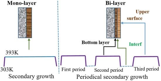
:A facile periodical secondary growth method, based on conventional secondary growth, is proposed to prepare bilayer TS-1 membranes. The novel periodical secondary growth consists of two or several periods, which involve three steps: the temperature is programmed to a desired crystallization temperature as the first stage, followed by holding for a certain duration, and finally cooling to room temperature. This periodical crystallization model enables a bilayer TS-1 membrane to be produced, while the conventional secondary growth method produces a monolayer TS-1 membrane. The bilayer TS-1 membrane exhibits a superior defect-free structure and hydrophobic properties, as illustrated by SEM, gas permeance, pore size distribution analysis, and water contact angle measurement. It displays an earlier desalination separation factor compared to the monolayer TS-1 membrane. This work demonstrates that the periodical secondary growth is an advanced approach for preparing a bilayer zeolite membrane with excellent properties.
1. Introduction
Zeolite membranes have attracted much attention due to their well-defined internal structures and favorable thermal, chemical, and structural stabilities. Their potential applications involve membrane separators, membrane reactors, and selective sensors [1,2,3,4,5], which strongly depend on the membranes’ structure and their preparation process [6,7]. Hydrophobic and defect-free titanium silicate (TS-1) membrane is considered one of the promising models for potential applications in catalytic membrane reactors and separators. TS-1 membranes exhibit preferentially selective permeation of organic components from organic/water mixtures [8,9,10,11].
Bilayer zeolite membranes, consisting of a bottom layer and an upper surface layer, are superior to the conventional monolayer zeolite membranes [12]. Their first critical advantage is the defect-free pinhole feature [13]. This feature is associated with the upper surface layer, eliminating pinholes in the bottom layer. Moreover, the bottom layer may reduce the thermal stress between the membrane substrate (typically α-Al2O3 ceramic [14]) and the upper surface layer [15]. This “weakening” thus avoids thermal cracks, which are commonly recognized as defects in membranes [16,17]. Another critical advantage of the bottom layer is the depressing by-effect of the membrane substrate on the upper surface layer. One notable example is inhibition of Al release from the α-Al2O3 substrate, which further contributes to the enhancement of hydrophobic of pure silicate zeolite membranes. The bilayer structure is usually realized by tertiary growth of the membrane after the secondary growth with fresh synthesis gel [18,19]. Several drawbacks of this method were raised, including the renovation of the synthesis gel, messy preparation process, and low conversion to the expected zeolite membrane of gel. Therefore, preparing bilayer zeolite membranes by a facile process while efficiently utilizing the synthesis gel is considered to be necessary from economic, environmental, and efficiency perspectives.
Inspired by secondary growth [20] and crystallization mechanisms [21,22,23,24], we propose a novel periodical secondary growth approach to prepare the bilayer TS-1 zeolite membrane. This approach is based on intermittent crystallization, through controlling the crystallization temperature of the synthesis gel and then affecting the growth of the zeolite membrane [24,25]. Here, crystallization of the synthesis gel on the zeolite membrane is through a periodical “heating–holding–cooling” procedure. One typical period involves three steps: the temperature is programmed to a desired crystallization temperature as the first stage [26,27], followed by holding for a certain duration, and finally cooling to room temperature. The features of the prepared bilayer titanium silicate-1 (TS-1) zeolite membrane, such as the defect status and hydrophobic performance, can be easily tuned by using different numbers of periods. The most distinct advantage of this approach compared to the messy tertiary growth is the elimination of renewal of the fresh synthesis gel, which provides an economical and environmentally friendly process for achieving the expected membrane structure, with excellent separation properties. The obtained TS-1 membrane showed a potential application in desalination (used here for removal of NaCl), which is meaningful for water purification [28,29].
2. Experimental
2.1. Preparation
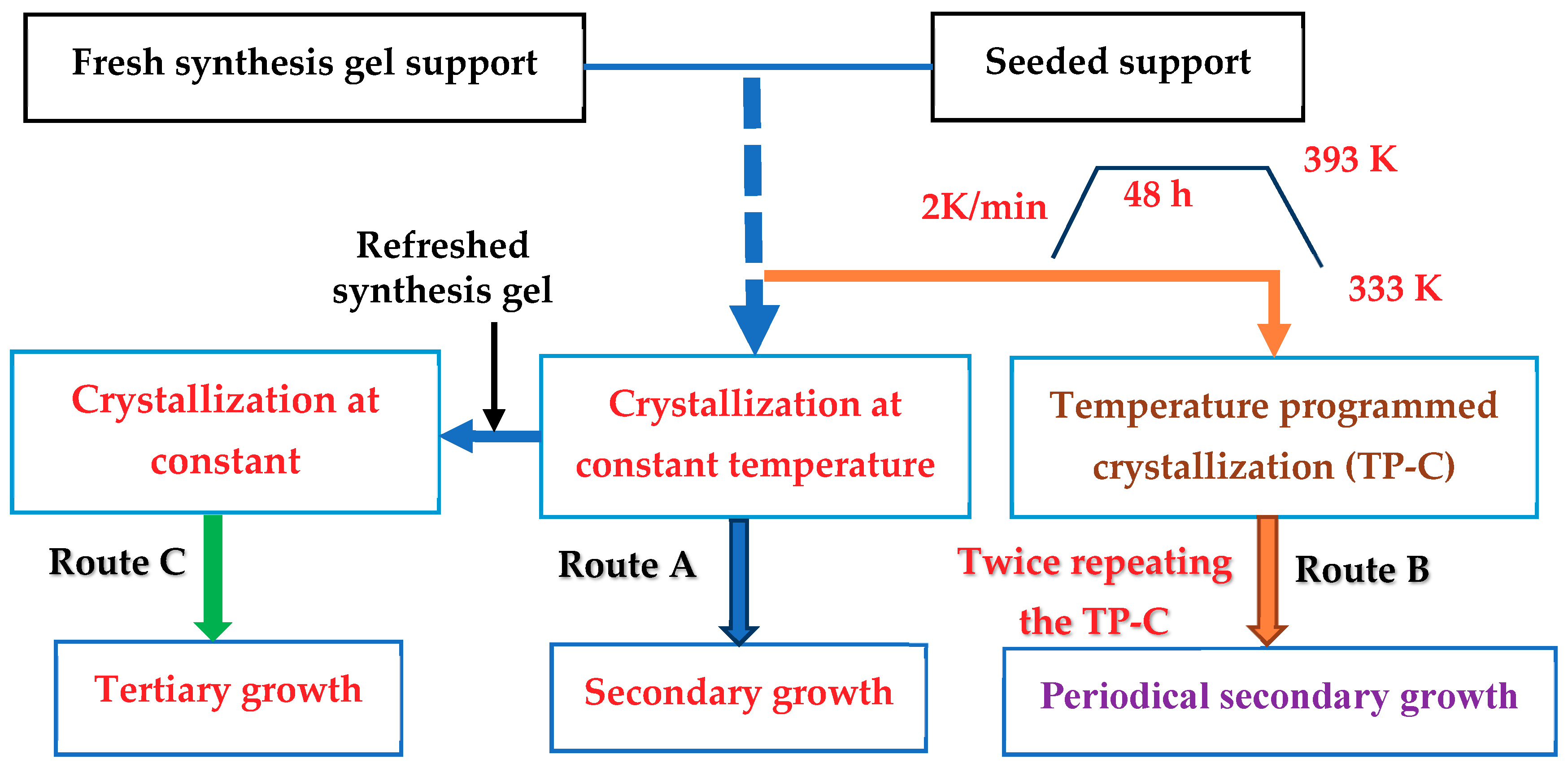
The spreading–wetting method was chosen to prepare a seeded support with a homemade SiO2/Al2O3 disc support (SiO2 content = 32 wt.% [30], outer diameter (OD) = 20 mm) [18,31]. Fresh synthesis gel of the TS-1 membrane was prepared following the protocol used in a previous study [32]. The typical bath composition for SiO2/TiO2/tetrapropylammonium hydroxide (TPAOH)/H2O was 1:0.05:0.08:150. Thirty milliliters of the fresh gel was subsequently transferred to a Teflon-lined stainless steel autoclave with an inner volume of 50 mL. The seeded support was horizontally immersed with its seeded face pointing downward in this gel, and was held on a homemade Teflon holder [17,33]. The autoclave was then sealed and placed into an oven with programmed heating and cooling temperatures. It was heated to a desired temperature (393 K) at a rate of 2 K/min, held for 48 h, cooled to 303 K at a rate of 5 K/min, and then held again for 3 hrs. This programmed heating–holding–cooling procedure comprises one crystallization period. Another two crystallization periods were subsequently performed, without renewing the synthesis gel. The total time for the crystallization periods was 144 hrs. This preparation method is suggested here as a periodical secondary growth, demonstrated as route B in Figure 1. A typical secondary growth, for reference, was carried out at 393 K, with continuous crystallization time of 144 h chosen, shown as route A in Figure 1. This provided unitary crystallization for the zeolite membrane growth. These obtained membranes were washed with deionized (DI) water, dried at 333 K, and activated through a Pd/SiO2 catalytic cracking method at 613 K [34]. Based on this conventional secondary growth, the periodical secondary growth interrupted the crystallization of the membrane growth, which was restarted and then performed as the periodical pattern with the original synthesis gel. The tertiary growth was similar to the periodical secondary growth and the synthesis gel was refreshed during each period (route C). Period-TS-1 and second-TS-1, hereinafter, denote the membranes obtained by the periodical secondary growth and secondary growth, respectively. The routes of those methods, as well as the tertiary growth method, are demonstrated in Figure 1. The periodical secondary growth is obviously easier to perform than the tertiary growth method, as shown in Table 1.
2.2. Characterization
Powder XRD patterns were collected within a range of 2θ = 20°–40° on a Rigaku D-max2500v/pc X-ray diffractometer (Tokyo, Japan) equipped with Cu-Kα radiation. The step size was selected as 0.0154° (step time of 1.0 s). The morphology of the samples was observed on a field emission scanning electron microscope (SEM, JSM-7500F, JEOL, Tokyo, Japan). Single gas (He) permeation measurements were designed to evaluate the quality of the TS-1 membranes. The as-synthesized TS-1 membranes were claimed to be free of defects when their permeance (f) was less than 10−10 (mol·s−1·Pa−1·m−2). The He permeance of the activated TS-1 membranes was also tested with varied pressures (0.1–0.5 MPa), which were plotted as a function of varying average pressure (Pav, MPa) and fitted with a dusty-gas model (f = α + β·Pav, where the permeability coefficients α and β are attributed to Knudsen and viscous flow, respectively [35]). The permeability coefficients β is related to the viscous flow owing to the defects. The activated TS-1 membranes were regarded as free of defects when their f values were barely independent of Pav [36]. The defects were also directly revealed by a permporometry measurement, giving a pore size distribution in the zeolite membrane [37]. The surface elemental composition of the zeolite membrane was analyzed by energy-dispersive X-ray spectroscopy (EDX) on an INCA energy apparatus (Oxford Instruments, Abingdon, UK). The contact angel (CA) was measured at room temperature on a CA system (JC2000A, POWEREACH Shanghai, Shanghai, China). All ESI–MS results were obtained by direct infusion (0.6 mL·h−1) into a Bruker Impact II mass spectrometer with z-spray alignment of the ESI source (capillary voltage of 3.5 kV, desolvation temperature of 393 K). The water droplets (about 0.8 μL) were dropped onto the surface, and the average value of the contact angle was calculated from five measurements at different positions for each sample.
2.3. Membrane Desalination
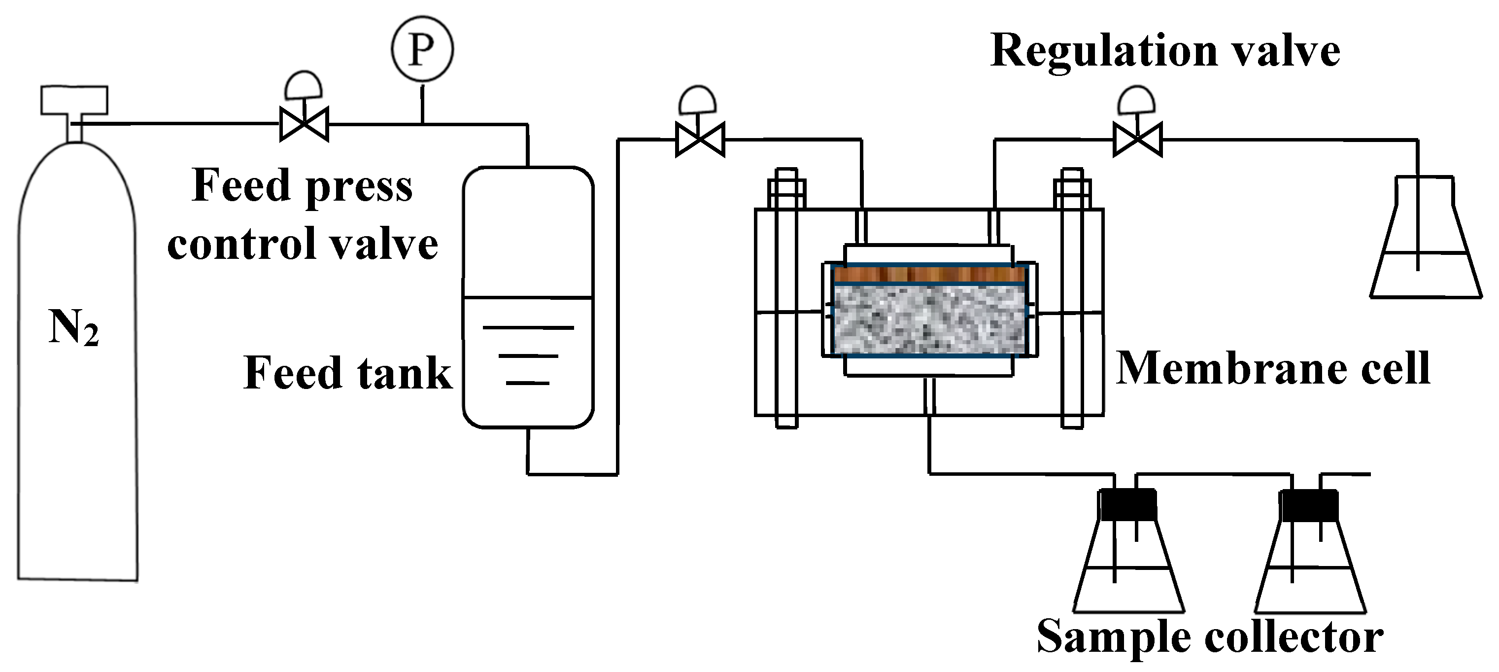
Desalination performance (here used for removal of NaCl) of the TS-1 membranes was carried out in reverse osmosis (RO) modes, similar to previous studies [29,38]. The setup was performed in a laboratory obeying the flow diagram, as shown in Figure 2. The membrane was first installed into the membrane cell and placed into the unit as shown. The feed vessel, including temperature control, was filled with sodium chloride (NaCl) solution (0.1 mol/L). The operating pressure (1.4 MPa) was supplied by feeding N2 into the vessel and was maintained constantly during the test. The desalination experiments were conducted in a cross-flow setup with the NaCl solution being fed under pressure on the outside and permeating to the inside of the membrane. The test temperature was controlled at 298 K. The collected flush sample was analyzed for Na+ anions using an inductive coupled plasma (ICP) emission spectrometer. The resulting flux was measured, while the separation factor (Na+ rejection) was calculated by rejection (%) = (CNa,f − CNa,p)/CNa,f × 100, where CNa,f and CNa,p were ICP-measured Na+ concentrations in the feed and permeate solutions, respectively [29,38].
3. Results and Discussion
3.1. Crystal Structure and Morphology
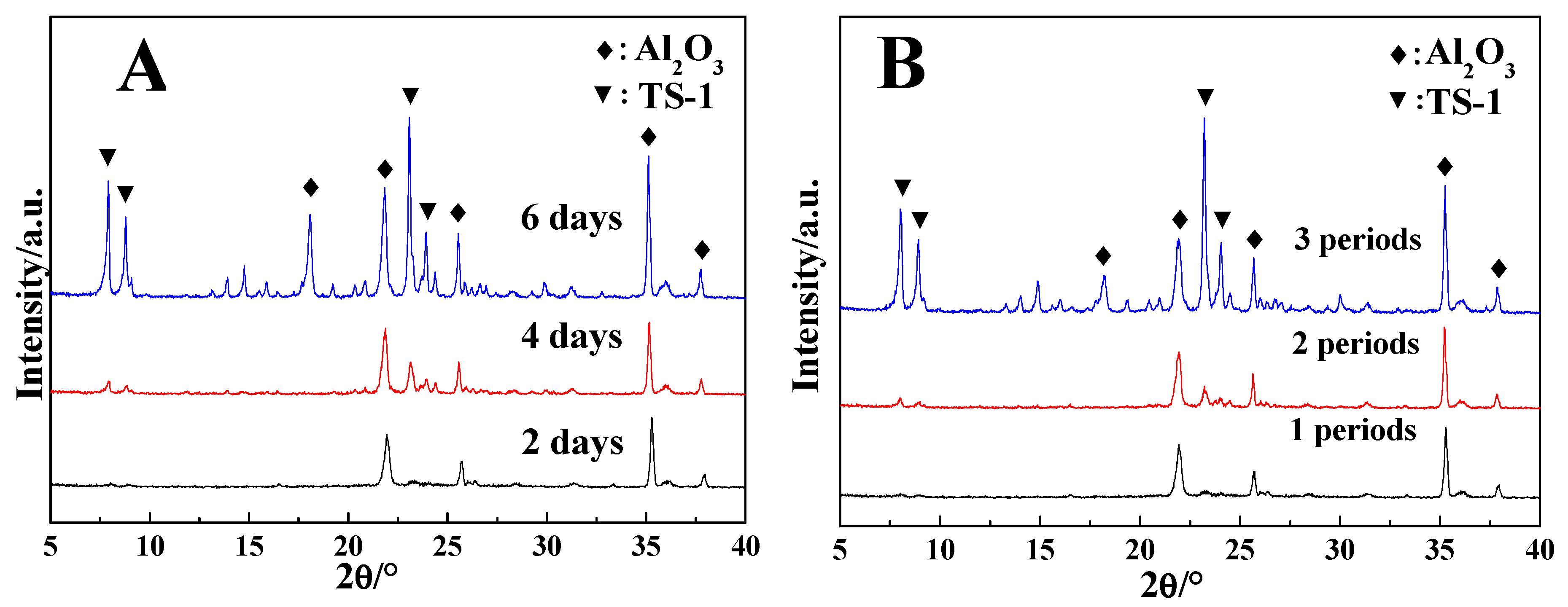
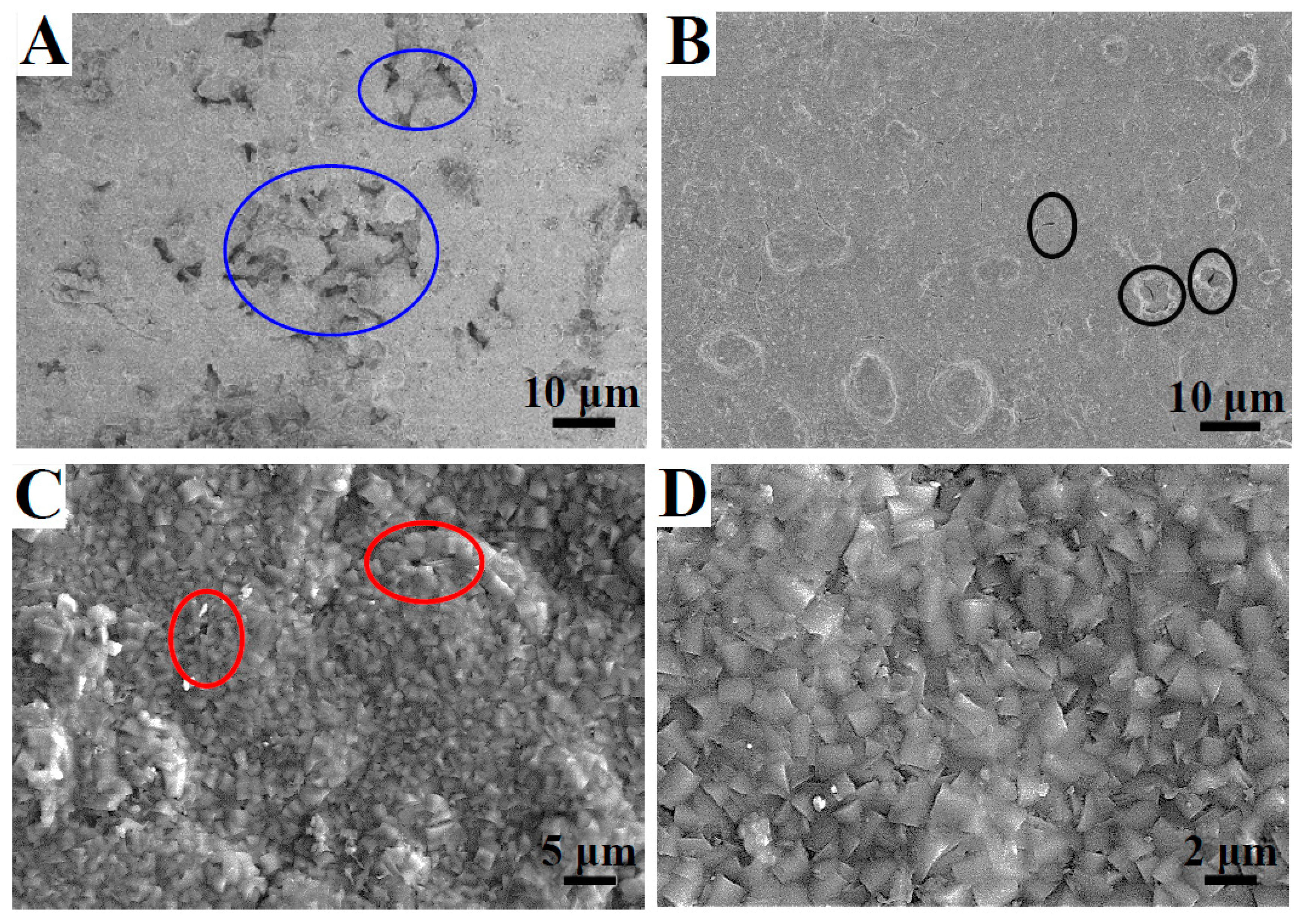
The XRD patterns of period-TS-1 and second-TS-1 are shown in Figure 3. The peaks at 2θ = 7.8°, 8.8°, 23.2°, 23.8°, 24.2°, and 29.3° indicated the formation of a typical TS-1 crystal structure. Those peaks resulted from types of crystal surfaces and illustrate the random orientation of the membrane [18,28]. The intensities increased with prolonged crystallization time, which was associated with more TS-1 crystal on the Al2O3 support. To further confirm the structure of these samples, SEM was performed to reveal the membrane morphology. Surface morphology was observed from top-view SEM images, shown in Figure 4A–D. A bare support surface and the TS-1 crystal were noted in the SEM image for the second-TS-1, with had a crystallization time of only 2 days (Figure 4A). When the crystallization time was prolonged to 4 days (Figure 4B), the bare support was further covered by the TS-1 crystal, but there was not a continuous intergrowth membrane. The crystallization time of 6 days (Figure 4C–F) enabled formation of the continuous TS-1 membrane, which displayed an intergrowth structure composed of polycrystalline. Pinholes (known as nonzeolite pores) were noted in detail and are marked with ellipses in Figure 4A (second-TS-1 membranes). This was also confirmed by the permporometry measurement (discussed in the following section), giving the pore size distribution of the zeolite membrane. Another feature of the second-TS-1 membranes was a monolayer approximately 3 μm thick, as shown in cross-sectional SEM images (Figure 4E, and the enlarged graph in Figure 4F). Such a layer was characterized as the TS-1 membrane by the above XRD results. Similar monolayer zeolite membranes with the pinholes were commonly obtained using the conventional secondary growth method, as well as with the in situ growth method [13,39]. These pinholes, however, can certainly be covered by another zeolite layer obtained using a tertiary growth, typically producing a bilayer zeolite membrane [18]. It is worth noting that another fresh synthesis gel must be adopted for the tertiary growth, following the secondary growth (shown as route C in Figure 1). This not only increases consumption of the raw materials (especially for the expensive TPAOH template), but also leads to a messy preparation process. Moreover, only a limited amount of the synthesis gel used in the tertiary growth converts to the expected zeolite membrane, as it mostly produces zeolite powder as a by-product. This leads to the limited selectivity of the zeolite membrane in this process, as well as the secondary growth. Therefore, preparing the bilayer zeolite membrane with a facile process by efficiently utilizing the synthesis gel was considered to be necessary from economic, environmental, and efficiency perspectives. It is worth pointing out that the preparation experiments were carried out at least twenty times, proving the reproducibility of the period-TS-1 membrane.
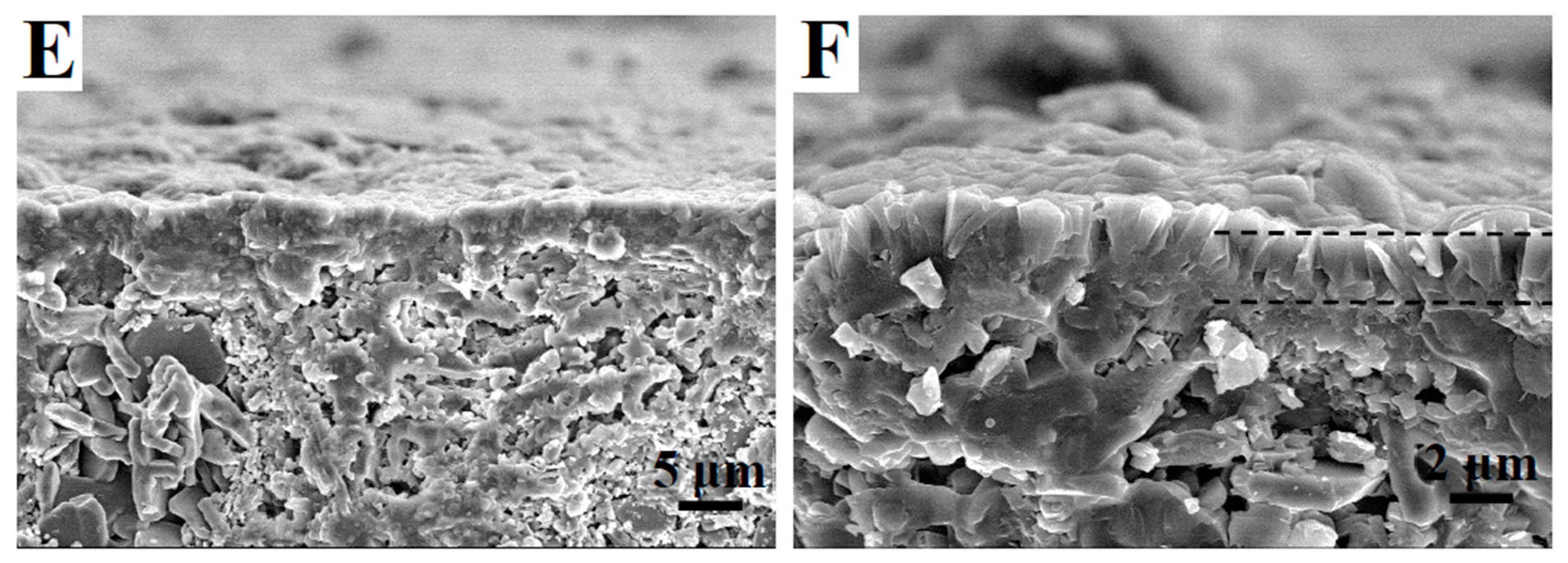
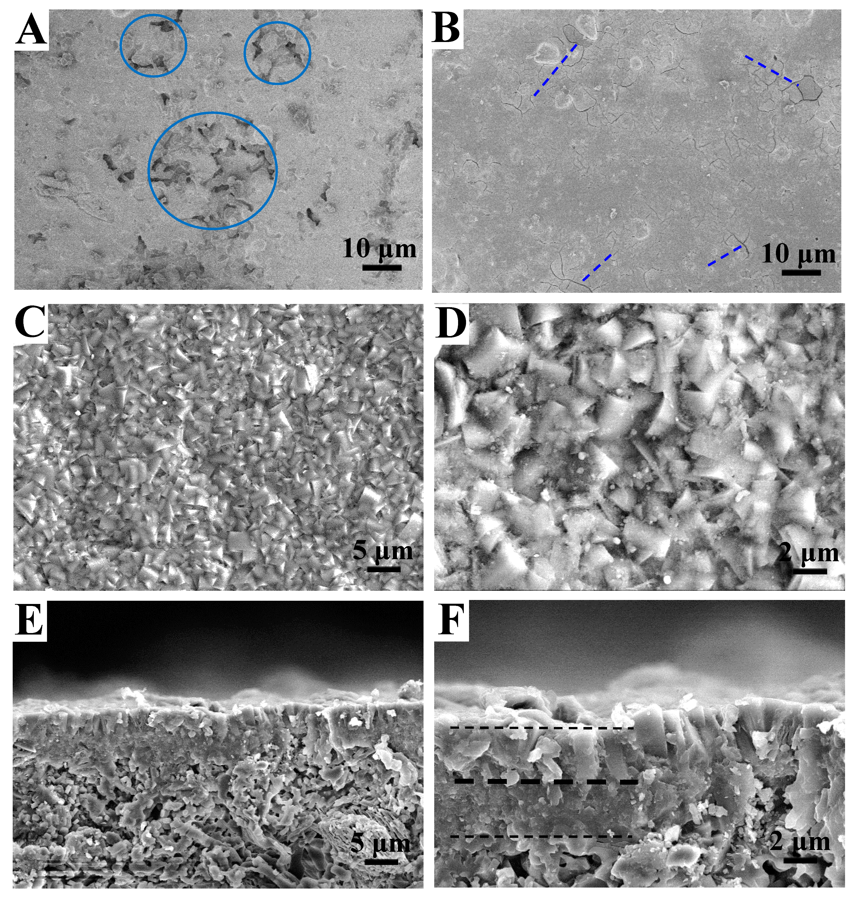
Based on a recognized crystallization mechanism [21,22,23,24], active silica species (typically orthosilicic acid) could stick to the nucleation center and then crystallize as zeolite or the zeolite membrane. The fresh synthesis gel with the active silica species certainly enabled the formation of the zeolite crystal. When the crystallization was performed for a period of time, the synthesis gel with the residual active silica species maintained the feasibility of generating the zeolite. With this feasibility, the periodical secondary growth method (without refreshing the synthesis gel) was proposed, as illustrated by route B in Figure 1. This method generates the polycrystalline membrane with an important interface feature, as is distinctly shown in Figure 5. Consistent with the second-TS-1, prolonging the crystallization time (i.e., increasing the crystallization periods) favored TS-1 crystal growth as the membrane. One crystallization period produced the TS-1 crystal on the support, while two crystallization periods led to an observable zeolite membrane with some cracks (Figure 5A,B). Three crystallization periods, corresponding to 6 days (Figure 5C–F), resulted in a continuous nondefective membrane. The zeolite membrane, generated during the former crystallization period, provided the seeding effect and favored the zeolite crystal growth during the next crystallization period. The periodical growth pattern thus delivered a thicker and nondefective zeolite membrane. For this period-TS-1 membrane, its thickness was estimated to be approximately 8 μm (Figure 5E), which was much thicker than that (3 μm) of the second-TS-1 membrane (Figure 5F); a bilayer structure was noted, composed of a bottom layer and an upper surface layer, as marked with dashed lines in Figure 5F. The upper surface layer thickness was measured to be approximately 4 μm. During these growth periods, the synthesis gel was analyzed with ESI-MS spectra and was not obviously changed. The orthosilicic acid, (Si(OH)4 (m/e = 97), was recognized as the basic building unit (BBU) for the zeolite. It remained and enabled the formation of the TS-1 crystal during different crystallization periods. This behavior was similar to the secondary growth with varied crystallization times (Figure 6A,B). The SiO4 species continuously reacted as poly-silicates, crystallized as the TS-1 crystal, and generated the monolayer membrane during the conventional secondary growth method. During the periodical crystallization, the crystallization was controlled by adjusting the crystallization temperature, while the zeolite membrane was produced after the second period. That bilayer structure, thus, may relate to the cooling step of the periodical secondary growth, which resulted in crystallization interruption. Its formation mechanism is based on intermittent crystallization [24] and is illustrated in Figure 6C,D. The zeolite growth in the first period is considered as a heteroepitaxial growth of zeolite on the α-Al2O3 substrate caused by the induction effect of the seed [40]. Cooling the synthesis mixture (using the autoclave) gel to 303 K stopped the crystallization and interrupted the heteroepitaxial growth after the first crystallization period. The zeolite growth was restarted on the zeolite upper membrane layer formed in the previous period via the epitaxial growth model once the synthesis gel was heated to 393 K. The two growth periods enabled a zeolite layer with a thickness of approximately 4 μm to be formed, which was thicker than that of the second-TS-1 membranes. This may be attributed to the strong induction effect of the possible zeolite layer generated during the first growth period. The same interruption was observed in the third growth period, where the zeolite layer had the same thickness of ca. 4 μm. The zeolite layers of the bilayer structure were named as the bottom and upper surface layers, which were formed during the first or second and third periods, respectively. Therefore, the pinholes in the bottom layer were certainly covered by the upper surface layer, which reduced the defect of the obtained membrane. However, the pinholes in the monolayer membrane, associated with the continuous crystal growth, were exposed and further modification was required [13]. Those significant differences between the bilayer and monolayer TS-1 membrane were directly confirmed by observing pore size distributions in the membranes.
3.2. Pore Distribution of the TS-1 Membrane
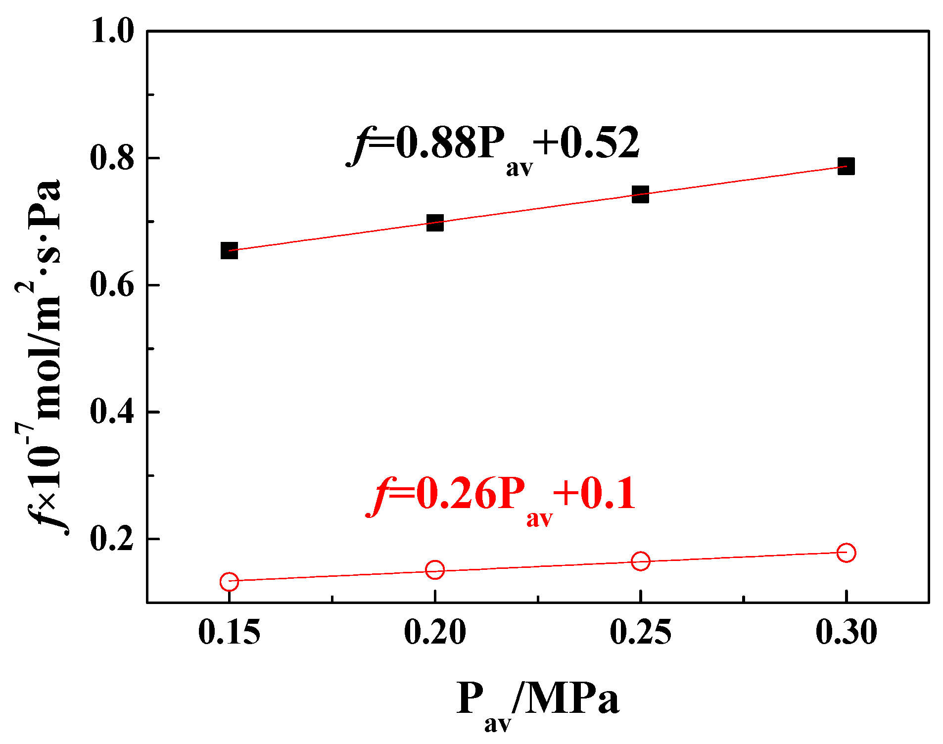
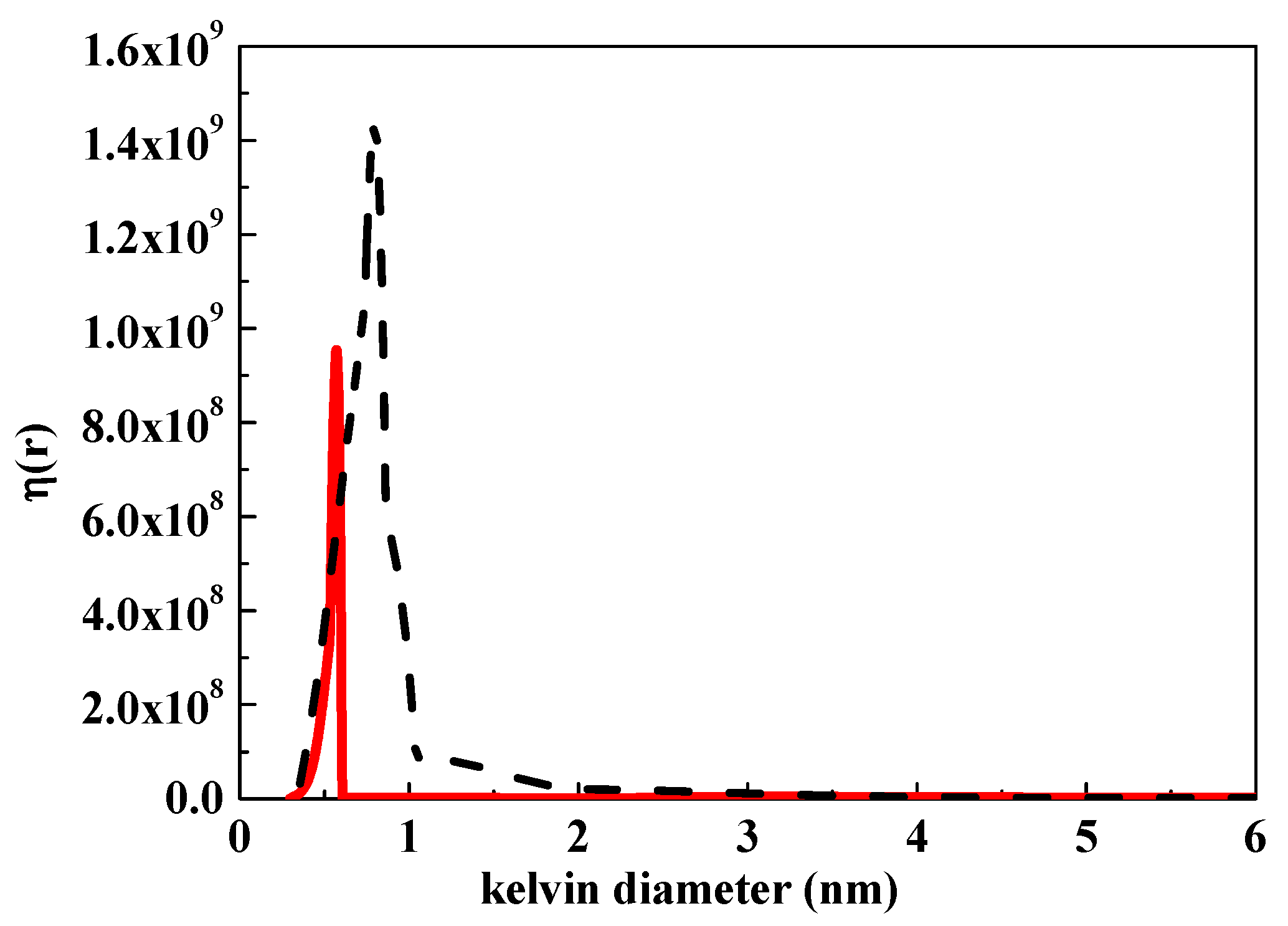
These results suggest that the crystallization over 6 days or 3 periods favored the formation of the continuous TS-1 membrane. To check the membrane quality, He permeance was first tested. The permeance was defined as f = F/L = Q/S(Ph − Pl), where f is the permeance (mol·s−1·Pa−1·m−2), F is the permeability (mol·m·s−1·Pa−1·m−2), L is the membrane thickness (m), Q is the molar gas flow rate (mol·s−1), S is the membrane area (m2), and Ph and Pl are the upstream and downstream pressure (Pa), respectively. The value for the as-synthesized second-TS-1 membrane was measured as 5 × 10⁻⁸ mol·s−1·Pa−1·m−2, which indicates a defective feature. However, an undetectable He permeance (< 10−10 mol·s−1·Pa−1·m−2) was observed for the period-TS-1 membrane, suggesting it is defect-free. It is believed that the TS-1 membranes still held distinguish He gas permeance properties after being activated by the Pd/SiO2 catalytic cracking method [18,30]. The He permeance is plotted as a function of varying average pressure and the following dusty gas model is used to fit the data: f = α + β·Pav, where the permeability coefficients α and β are attributed to Knudsen and viscous flow in the zeolite membrane, respectively. The obtained α and β values were compatible with the evaluated pore size. Generally, the zeolite pore (< 1 nm) contributes to the Knudsen diffusion, while the nonzeolite pores (> 1 nm) caused by the defects result in the viscous flow. The low viscous flow coefficient (0.26) was derived after linear fitting (Figure 7) based on the dusty gas model [35,36,41,42], indicating negligible viscous flow for the period-TS-1 membranes. This suggests a low defect-free structure in the period-TS-1 membrane. The higher viscous flow coefficient value of 0.88 may indicate a certain number of defects in the second-TS-1 membranes. The difference between period-TS-1 and second-TS-1 membranes was also confirmed by a permporometry measurement of the pore size distribution for the activated zeolite membrane. The period-TS-1 membrane displayed a mono pore size of 0.5–0.6 nm, which was the same as its zeolite pore size (0.5–0.6 nm). A wide pore size distribution of 0.4–2 nm was observed on the second-TS-1 membrane (Figure 8). These pores, except those measuring 0.5–0.6 nm, were regarded as defects (pinholes or cracks) [43], and resulted in higher Knudsen diffusion permeance (0.52×10⁻⁷ mol·s-1·Pa-1·m-2) than that of the period-TS-1 membrane. These results are consistent with the above SEM findings. As discussed in the former section, the reduction of defects (the nonzeolite pore) is related to the upper surface layer, with which the possible pinholes in the bottom layer can be covered and eliminated. The monolayer structure of the second-TS-1 membrane, prepared by the continuous heteroepitaxial growth, may not have “eliminated” this effect, thus resulting in defective membranes [13,22,36].
3.3. Elemental Composition and Hydrophobicity
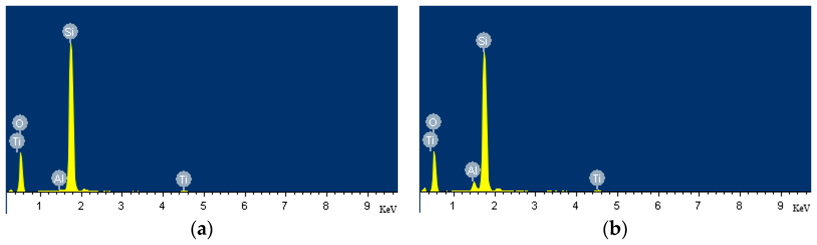
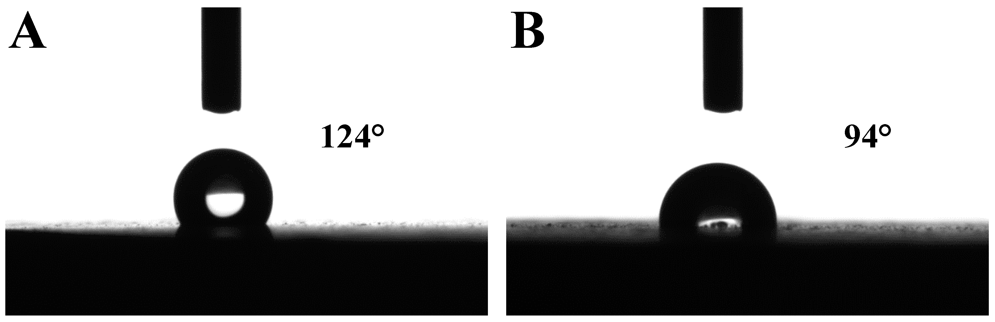
Another function of the bottom layer is to suppress the release of Al from α-Al2O3 base substrate. The mole ratio of Al/Ti/Si for the period-TS-1 membrane, obtained by a surface EDX analysis (Figure 9), was determined to be 1.01:2.45:100, while that of the second-TS-1 membrane was 6.09:1.42:100. The lower Al and lower Ti contents of the period-TS-1 compared to second-TS-1 membrane indicates the inhibition of Al release from the support by the bottom layer. The low Al content in the period-TS-1 membrane results in hydrophobic characteristics, as evidenced by the water contact angle of 124° (Figure 10A). A weak hydrophobic nature is noted for the second-TS-1 membrane, with a water contact angle of 94° (Figure 10B). This indicates the superiority of the bilayer structure for enhancing hydrophobicity.
3.4. Membrane Desalination Properties
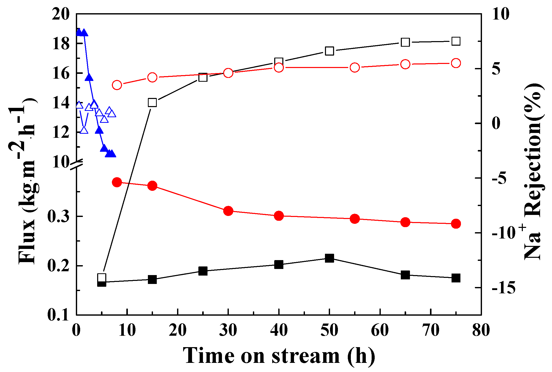
The desalination properties of the TS-1 membranes are shown in Figure 11. At a constant temperature of 298 K and pressure of 1.4 MPa, the period-TS-1 membrane displayed a flux of ca. 0.20 kg·m−2·h−1, which was less than that of the second-TS-1 (ca. 0.30 kg·m−2·h−1), which is consistent with the gas permeance test shown above. The higher water flux and gas permeance for the second-TS-1 is related to the defects in the relatively thin membrane, as shown by the foregoing SEM images and pore size analysis. The defect, revealed as being pinholes, generally generates pores with sizes >1.0 nm, and thus contributes to a certain percentage of the supernumerary flux. This behavior was also confirmed by a much higher flux (> 10.0 kg·m−2·h−1) observed in a reference period-TS-1 membrane activated by calcination, in which the crack defects exist [18,32]. This reference sample hereinafter is denoted as the defect-period-TS-1 membrane. These results, as well as the SEM, gas permeance, and pore size characterizations, prove the superior defect-free nature of the period-TS-1 membrane compared to the second-TS-1 membrane. The separation properties of different samples were investigated by measuring the separation factor (Na+ rejection ratio), as shown in Figure 11. Na+ rejection of only ca. 5% in RO mode was observed for the second-TS-1 membrane. This poor separation factor may be related to the weak hydrophobic properties of the second-TS-1 membrane, indicated by the water CA around 90°, which was due to the trace Al content in its structure, as confirmed by the EDX analysis. The period-TS-1 held a prior separation factor of ca. 7% after 40 h in the stream test, which may be ascribed to its defect-free structure. To confirm this assumption, the test over the defect-period-TS-1 membrane was performed. The defect-period-TS-1 membrane showed much poorer Na+ rejection (ca. 1%). The separation properties test results suggest the beneficial effect of the defect-free structure on improving the membrane separation factor, which is attributed to the bilayer TS-1 membrane prepared by the facile periodical secondary growth method. It remains necessary to improve the poor membrane separation properties. Based on the defect-free bilayer TS-1 membrane, we have developed a basic treatment to generate hierarchical TS-1 membranes to improve the membrane flux. Surface modification of the resulting hierarchical TS-1 membrane with triethoxyfluorosilane would enhance the separation factor. These results will follow soon.
4. Conclusions
A facile periodical secondary growth approach is provided to prepare a TS-1 zeolite membrane with a bilayer structure, consisting of bottom and upper surface layers. The bilayer structure was identified by SEM. The SEM, gas permeance, and pore size distribution analysis confirmed its defect-free structure. The release of Al from the support was inhibited by the existence of the bottom layer in the bilayer, which was indicated by EDX analysis. Water contact angle measurements illustrated the superior hydrophobic nature of the obtained bilayer membrane, which was attributed to the low Al content in the period-TS-1 membrane. The superior defect-free hydrophobic period-TS-1 membrane exhibited prior separation factors to the defective second-TS-1 membrane in a RO desalination test. This work demonstrates that periodical secondary growth can be an advanced approach for preparing bilayer zeolite membranes with excellent properties.
Author Contributions
Conceptualization, Q.Z.; Methodology, X.L.; Formal Analysis, X.L.; Investigation, Y.L.; Resources, X.L.; Data Curation, Y.L.; Writing—Original Draft Preparation, Q.Z. and Y.L.; Writing—Review & Editing, L.M.; Supervision, X.L.; Funding Acquisition, L.M.
Funding
This research was funded by National Natural Science Foundation of China (51602069), the Fundamental Research Funds for the Central Public Welfare Scientific Institution (K-JBYWF-2017- T07), Haikou City’s “Thirteenth Five-Year” Marine Economic Innovation, and the Development Demonstration City Project (HHCL201810).
Acknowledgments
The authors thank Pingping Zhang and Tianyi Wang for some help in the work.
Conflicts of Interest
The authors declare no conflict of interest.
References
- Lew, C.M.; Cai, R.; Yan, Y. Zeolite Thin Films: From Computer Chips to Space Stations. Acc. Chem. Res. 2010, 43, 210–219. [Google Scholar] [CrossRef] [PubMed]
- Varoon, K.; Zhang, X.; Elyassi, B.; Brewer, D.D.; Gettel, M.; Kumar, S.; Lee, J.A.; Maheshwari, S.; Mittal, A.; Sung, C.Y.; et al. Dispersible Exfoliated Zeolite Nanosheets and Their Application as a Selective Membrane. Science 2011, 334, 72–75. [Google Scholar] [CrossRef] [PubMed] [Green Version]
- Tsapatsis, M. Toward High-Throughput Zeolite Membranes. Science 2011, 334, 767–768. [Google Scholar] [CrossRef] [PubMed]
- Pham, T.C.T.; Kim, H.S.; Yoon, K.B. Growth of Uniformly Oriented Silica MFI and BEA Zeolite Films on Substrates. Science 2011, 334, 1533–1538. [Google Scholar] [CrossRef] [PubMed]
- Lai, Z.; Bonilla, G.; Diaz, I.; Nery, J.G.; Sujaoti, K.; Amat, M.A.; Kokkoli, E.; Terasaki, O.; Thompson, R.W.; Tsapatsis, M.; et al. Microstructural Optimization of A Zeolite Membrane for Organic Vapor Separation. Science 2003, 300, 456–460. [Google Scholar] [CrossRef] [PubMed]
- Choi, J.; Jeong, H.K.; Snyder, M.A.; Stoeger, J.A.; Masel, R.I.; Tsapatsis, M. Grain Boundary Defect Elimination in a Zeolite Membrane by Rapid Thermal Processing. Science 2009, 325, 590–593. [Google Scholar] [CrossRef]
- Zhou, M.; Korelskiy, D.; Ye, P.; Grahn, M.; Hedlund, J. A Uniformly Oriented MFI Membrane for Improved CO2 Separation. Angew. Chem. Int. Ed. 2014, 53, 3492–3495. [Google Scholar] [CrossRef]
- Wang, X.D.; Zhang, B.Q.; Liu, X.F.; Lin, J.Y.S. Synthesis of B-Oriented TS-1 Films on Chitosan-Modified α-Al2O3 Substrates. Adv. Mater. 2006, 18, 3261–3265. [Google Scholar] [CrossRef]
- Chen, X.; Chen, P.; Kita, H. Pervaporation through TS-1 Membrane. Microporous Mesoporous Mater. 2008, 115, 164–169. [Google Scholar] [CrossRef]
- Chen, P.; Chen, X.; Chen, X.; Kita, H. Preparation and Catalytic Activity of Titanium Silicalite-1 Zeolite Membrane with TPABr as Template. J. Membr. Sci. 2009, 330, 369–378. [Google Scholar] [CrossRef]
- Motuzas, J.; Mikutaviciute, R.; Gerardin, E.; Julbe, A. Controlled Growth of Thin and Uniform TS-1 Membranes by MW-Assisted Heating. Microporous Mesoporous Mater. 2010, 128, 136–143. [Google Scholar] [CrossRef]
- Wang, H.; Dong, X.; Lin, Y.S. Highly Stable Bilayer MFI Zeolite Membranes for High Temperature Hydrogen Separation. J. Membr. Sci. 2014, 450, 425–432. [Google Scholar] [CrossRef]
- Zhang, B.; Wang, C.; Lang, L.; Cui, R.; Liu, X. Selective Defect-Patching of Zeolite Membranes Using Chemical Liquid Deposition at Organic/Aqueous Interfaces. Adv. Funct. Mater. 2008, 18, 3434–3443. [Google Scholar] [CrossRef]
- Carreon, M.A.; Li, S.; Falconer, J.L.; Noble, R.D. Alumina-Supported SAPO-34 Membranes for CO2/CH4 Separation. J. Am. Chem. Soc. 2008, 130, 5412–5413. [Google Scholar] [CrossRef] [PubMed]
- Cho, C.H.; Oh, K.Y.; Kim, S.K.; Yeo, J.G.; Lee, Y.M. Improvement in Thermal Stability of NaA Zeolite Composite Membrane by Control of Intermediate Layer Structure. J. Membr. Sci. 2011, 366, 229–236. [Google Scholar] [CrossRef]
- Jeong, H.K.; Lai, Z.; Tsapatsis, M.; Hanson, J.C. Strain of MFI Crystals in Membranes: An In Situ Synchrotron X-ray Study. Microporous Mesoporous Mater. 2005, 84, 332–337. [Google Scholar] [CrossRef]
- Kim, E.; Choi, J.; Tsapatsis, M. On Defects in Highly a-Oriented MFI Membranes. Microporous Mesoporous Mater. 2013, 170, 1–8. [Google Scholar] [CrossRef]
- Liu, X.; Liu, Y.; Xu, L.; Zhang, B.; Ma, L. Spreading-Wetting Method for Highly Reproducible Tertiary Growth of Perfective Bilayer TS-1 Membranes. Appl. Surf. Sci. 2015, 343, 77–87. [Google Scholar] [CrossRef]
- Karanikolos, G.N.; Wydra, J.W.; Stoeger, J.A.; García, H.; Corma, A.; Tsapatsis, M. Continuous c-Oriented AlPO4-5 Films by Tertiary Growth. Chem. Mater. 2007, 19, 792–797. [Google Scholar] [CrossRef]
- Huang, A.; Liang, F.; Steinbach, F.; Gesing, T.M.; Caro, J. Neutral and Cation-Free LTA-Type Aluminophosphate (AlPO4) Molecular Sieve Membrane with High Hydrogen Permselectivity. J. Am. Chem. Soc. 2010, 132, 2140–2141. [Google Scholar] [CrossRef]
- Ng, E.-P.; Chateigner, D.; Bein, T.; Valtchev, V.; Mintova, S. Capturing Ultrasmall EMT Zeolite from Template-Free Systems. Science 2012, 335, 70–73. [Google Scholar] [CrossRef] [PubMed] [Green Version]
- Lupulescu, A.I.; Rimer, J.D. In Situ Imaging of Silicalite-1 Surface Growth Reveals the Mechanism of Crystallization. Science 2014, 344, 729–732. [Google Scholar] [CrossRef]
- Lang, L.; Liu, X.; Jiang, H.; Lin, J.Y.S.; Zhang, B. Direct Evidence of the Evolutionary Mechanism of Zeolite Monolayers on the Substrate Surface in a Hydrothermal Reaction. Langmuir 2010, 26, 5895–5900. [Google Scholar] [CrossRef] [PubMed]
- Li, S.; Li, Z.; Bozhilov, K.N.; Chen, Z.; Yan, Y. TEM Investigation of Formation Mechanism of Monocrystal-Thick b-Oriented Pure Silica Zeolite MFI Film. J. Am. Chem. Soc. 2004, 126, 10732–10737. [Google Scholar] [CrossRef] [PubMed]
- Li, Y.; Pera-Titus, M.; Xiong, G.; Yang, W.; Landrivon, E.; Miachon, S.; Dalmon, J.A. Nanocomposite MFI-Alumina Membranes via Pore-Plugging Synthesis: Genesis of the Zeolite Material. J. Membr. Sci. 2008, 325, 973–981. [Google Scholar] [CrossRef]
- Yan, Y.; Chaudhuri, S.R.; Sarkar, A. Synthesis of Oriented Zeolite Molecular Sieve Films with Controlled Morphologies. Chem. Mater. 1996, 8, 473–479. [Google Scholar] [CrossRef]
- Zhang, X.L.; Qiu, L.F.; Ding, M.Z.; Hu, N.; Zhang, F.; Zhou, R.F.; Chen, X.S.; Kita, H. Preparation of Zeolite T Membranes by a Two-Step Temperature Process for CO2 Separation. Ind. Eng. Chem. Res. 2013, 52, 16364–16374. [Google Scholar] [CrossRef]
- Fane, A.G.; Wang, R.; Hu, M.X. Synthetic Membranes for Water Purification: Status and Future. Angew. Chem. Int. Ed. 2015, 54, 3368–3386. [Google Scholar] [CrossRef]
- Zhu, B.; Hong, Z.; Milne, N.; Doherty, C.M.; Zou, L.; Lin, Y.S.; Hill, A.J.; Gu, X.; Duke, M. Desalination of Seawater Ion Complexes by MFI-Type Zeolite Membranes: Temperature and Long Term Stability. J. Membr. Sci. 2014, 453, 126–135. [Google Scholar] [CrossRef] [Green Version]
- Chen, S.; Liu, X.; Zhang, B. Preparation and Properties of Porous α-Al2O3 Based Ceramic Disk Substrates. J. Inorg. Mater. 2013, 28, 599–604. [Google Scholar] [CrossRef]
- Liu, X.; Ma, X.; Liu, Y.; Zhang, B. Preparation of Perfective TAPO-5 Membrane through Tertiary Growth with Amorphous Seed. J. Inorg. Mater. 2015, 30, 555–560. [Google Scholar] [CrossRef]
- Deng, X.; Wang, Y.; Shen, L.; Wu, H.; Liu, Y.; He, M. Low-Cost Synthesis of Titanium Silicalite-1 (TS-1) with Highly Catalytic Oxidation Performance through a Controlled Hydrolysis Process. Ind. Eng. Chem. Res. 2013, 52, 1190–1196. [Google Scholar] [CrossRef]
- Wang, X.; Zhang, P.; Liu, X.; Zhang, B. Fabrication and Characterization of TS-1 Films on α-Al2O3 Substrates Using TiCl3 as Titanium Source. Appl. Surf. Sci. 2007, 254, 544–547. [Google Scholar] [CrossRef]
- Liu, X.; Xu, L.; Zhang, B.; Liu, X. Template Removal from AFI Aluminophosphate Molecular Sieve by Pd/SiO2 Catalytic Hydrocracking at Mild Temperature. Microporous Mesoporous Mater. 2014, 193, 127–133. [Google Scholar] [CrossRef]
- Kanezashi, M.; O’Brien, J.; Lin, Y.S. Template-Free Synthesis of MFI-Type Zeolite Membranes: Permeation Characteristics and Thermal Stability Improvement of Membrane Structure. J. Membr. Sci. 2006, 286, 213–222. [Google Scholar] [CrossRef]
- Xiao, W.; Chen, Z.; Zhou, L.; Yang, J.; Lu, J.; Wang, J. A simple Seeding Method for MFI Zeolite Membrane Synthesis on Macroporous Support by Microwave Heating. Microporous Mesoporous Mater. 2011, 142, 154–160. [Google Scholar] [CrossRef]
- Wang, C.; Liu, X.; Cui, R.; Zhang, B. In Situ Evaluation of Defect Size distribution for Supported Zeolite Membranes. J. Membr. Sci. 2009, 330, 259–266. [Google Scholar] [CrossRef]
- Duke, M.C.; O’Brien-Abraham, J.; Milne, N.; Zhu, B.; Lin, J.Y.S.; Diniz da Costa, J.C. Seawater Desalination Performance of MFI Type Membranes Made by Secondary Growth. Sep. Purif. Technol. 2009, 68, 343–350. [Google Scholar] [CrossRef]
- Wang, C.; Liu, X.; Cui, R.; Zhang, B. Formation and Reparation of Defects in Zeolite Membranes. Prog. Chem. 2008, 20, 1860–1867. [Google Scholar]
- Lang, L.; Liu, X.; Zhang, B. Synthesis and Characterization of (h0h)-Oriented Silicalite-1 Films on α-Al2O3 Substrates. Appl. Surf. Sci. 2008, 254, 2353–2358. [Google Scholar] [CrossRef]
- Weyd, M.; Richter, H.; Puhlfürß, P.; Voigt, I.; Hamel, C.; Seidel-Morgenstern, A. Transport of Binary Water–Ethanol Mixtures through a Multilayer Hydrophobic Zeolite Membrane. J. Membr. Sci. 2008, 307, 239–248. [Google Scholar] [CrossRef]
- Das, S.K. General Dusty Gas Model for Porous Media with a Specified Pore Size Distribution. Chem. Eng. Sci. 2019, 203, 293–301. [Google Scholar] [CrossRef]
- Ma, X.; Wang, H.; Wang, H.; Brien-Abraham, J.O.; Lin, Y.S. Pore Structure Characterization of Supported Polycrystalline Zeolite Membranes by Positron Annihilation Spectroscopy. J. Membr. Sci. 2015, 477, 41–48. [Google Scholar] [CrossRef] [Green Version]
Figure 1.
Preparation routes of the secondary growth (route A), tertiary growth (route B), and periodical secondary growth method (route C).
Figure 1.
Preparation routes of the secondary growth (route A), tertiary growth (route B), and periodical secondary growth method (route C).

Figure 2.
Schematic diagram of the RO system.

Figure 3.
XRD patterns of the (A) period-TS-1 and (B) second-TS-1 membranes with varied crystallization times (2–6 days, with 1–3 periods).
Figure 3.
XRD patterns of the (A) period-TS-1 and (B) second-TS-1 membranes with varied crystallization times (2–6 days, with 1–3 periods).

Figure 4.
Top and cross-section view SEM images of the second-TS-1 membrane synthesized with varied crystallization times: (A) 2 days, (B) 4 days, (C–F) 6 days; blue circles mark the bare support, black circles mark the cracks, red circles mark the pinholes, while the black dashed lines mark the membrane interface.


Figure 5.
Top and cross-section view images of the period-TS-1 membrane synthesized with varying crystallization periods: (A) 1 period, (B) 2 periods (C–F), 3 periods; blue circles mark the bare support, blue dashed lines mark the cracks, black dashed lines mark the membrane interface.
Figure 5.
Top and cross-section view images of the period-TS-1 membrane synthesized with varying crystallization periods: (A) 1 period, (B) 2 periods (C–F), 3 periods; blue circles mark the bare support, blue dashed lines mark the cracks, black dashed lines mark the membrane interface.

Figure 6.
ESI-MS spectra of the synthesis gel during the crystallization process for the second-TS-1 (A) and period-TS-1 membranes (B). Scheme of the growth modes of the secondary growth (C) and the periodical secondary growth (D) methods.
Figure 6.
ESI-MS spectra of the synthesis gel during the crystallization process for the second-TS-1 (A) and period-TS-1 membranes (B). Scheme of the growth modes of the secondary growth (C) and the periodical secondary growth (D) methods.

Figure 7.
He permeance of the period-TS-1 (○) and second-TS-1 (■) membranes.

Figure 8.
Pore size distribution of the period-TS-1 (solid line) and second-TS-1 (dash line) membranes.
Figure 8.
Pore size distribution of the period-TS-1 (solid line) and second-TS-1 (dash line) membranes.

Figure 9.
EDX spectra of the period-TS-1 (a) and second-TS-1 (b) membranes.

Figure 10.
Water contact angle of the period-TS-1 (A) and second-TS-1 (B) membranes.

Figure 11.
Flux (solid symbol) and Na+ rejection (open symbol) in RO mode for the period-TS-1 (■□), defect-period-TS-1 (▲△), and second-TS-1 membranes (●○).
Figure 11.
Flux (solid symbol) and Na+ rejection (open symbol) in RO mode for the period-TS-1 (■□), defect-period-TS-1 (▲△), and second-TS-1 membranes (●○).


Table 1.
Features of the secondary growth (second-TS-1), periodical secondary growth (period-TS-1), and tertiary growth.
Table 1.
Features of the secondary growth (second-TS-1), periodical secondary growth (period-TS-1), and tertiary growth.
| Methods | Route in Figure 1 | Crystallization Pattern | Synthesis Gel |
|---|---|---|---|
| Secondary growth | A | Continuous | original |
| Periodical secondary growth | B | Periodical crystallization | original |
| Tertiary growth | C | Periodical crystallization | refreshed |
© 2019 by the authors. Licensee MDPI, Basel, Switzerland. This article is an open access article distributed under the terms and conditions of the Creative Commons Attribution (CC BY) license (http://creativecommons.org/licenses/by/4.0/).
Share and Cite
MDPI and ACS Style
Zhang, Q.; Liu, Y.; Liu, X.; Ma, L. Facile Preparation of Bilayer Titanium Silicate (TS-1) Zeolite Membranes by Periodical Secondary Growth. Coatings 2019, 9, 850. https://doi.org/10.3390/coatings9120850
AMA Style
Zhang Q, Liu Y, Liu X, Ma L. Facile Preparation of Bilayer Titanium Silicate (TS-1) Zeolite Membranes by Periodical Secondary Growth. Coatings. 2019; 9(12):850. https://doi.org/10.3390/coatings9120850
Chicago/Turabian StyleZhang, Qi, Yong Liu, Xuguang Liu, and Laibo Ma. 2019. "Facile Preparation of Bilayer Titanium Silicate (TS-1) Zeolite Membranes by Periodical Secondary Growth" Coatings 9, no. 12: 850. https://doi.org/10.3390/coatings9120850
Note that from the first issue of 2016, this journal uses article numbers instead of page numbers. See further details here.