Article

Thin Film Fabrication and Characterization of Layered Rock Salt LiCoO2 on Quartz Glass Spray-Coated with an Aqueous Ammonia Solution Involving Metal Acetates

1
Applied Chemistry and Chemical Engineering Program, Graduate School, Kogakuin University, 2665-1 Nakano, Hachioji, Tokyo 192-0015, Japan
2
Department of Applied Physics, School of Advanced Engineering, Kogakuin University, 2665-1 Nakano, Hachioji, Tokyo 192-0015, Japan
*
Author to whom correspondence should be addressed.
Coatings 2019, 9(2), 97; https://doi.org/10.3390/coatings9020097
Submission received: 27 November 2018 / Revised: 22 January 2019 / Accepted: 31 January 2019 / Published: 5 February 2019

Abstract

:
A LiCoO2 thin film on a quartz glass substrate was fabricated by a wet process involving heat treatment of a precursor film spray-coated with an aqueous ammonia solution containing LiCH3COO and Co(CH3COO)2. The precursor film formed onto the substrate at 180 °C in air, and was heat treated at 500 °C in air for 0.5 h. The obtained film was spin-coated further with an ethanol-based precursor solution containing identical metal acetates, and heat treated at 500 °C in air for 0.5 h. The X-ray diffraction pattern of the resultant film showed only peaks assignable to the layered-rock-salt LiCoO2. Raman spectroscopy measurements revealed vibrational modes assignable to layered rock salt LiCoO2, with minor content of less than 5 mol% of spinel-type Co3O4. The field emission scanning electron microscopy images indicated that the resultant film was 0.21 μm thick, had no voids, and was a combination of small rounded grains measuring 18 nm in diameter and hexagonal grains larger than 0.2 μm in length. The Hall effect measurements indicated that the resultant thin film was a p-type semiconductor with electrical resistivity of 35(2) Ω·cm and a carrier concentration and carrier mobility of 8(2) × 1016 cm−3 and 2(1) cm2·V−1·s−1, respectively.

1. Introduction

Layered rock salt LiCoO2 (LCO) has been extensively studied and successfully applied as an Li intercalation compound in lithium-ion batteries (LIBs), due to its high specific energy-density and structural stability that promotes extended battery cyclability [1,2,3,4,5,6]. LIBs with electrodes that employ thin films of active materials, including LCO, are preferred over their bulk counterparts due to the much improved electronic and ionic conductivity, increased specific surface area, and ease of controlling the morphology. Additionally, the thin film electrodes are free from impurities such as binders and carbon fillers used in the fabrication of bulk electrodes.
Techniques such as magnetron sputtering and pulsed laser deposition (PLD) are capable of depositing high quality thin films of LCO [7,8]. However, they are associated with expensive and complicated experimental setups that require ultra-high vacuum systems. On the other hand, thin films of LCO have been fabricated via the sol-gel method [3,9,10,11] at high temperatures and prolonged annealing conditions, which are likely to lead to moderate lithium loss and compromise the electrochemical properties of the materials [3,12].
Recently, our group reported the fabrication of a novel thin film lithium-ion battery (LIB) that can be charged by light irradiation, thus functioning as a photovoltaic LIB (PV-LIB) [13]. The cathodic active material for this PV-LIB was a thin film of LCO deposited on fluorinated tin oxide (FTO) pre-coated glass substrate by the molecular precursor method (MPM). The MPM is an effective wet chemical process that was developed by the current authors for fabricating nanocrystalline thin films of metals and various metal oxides and phosphates [13,14,15,16,17,18,19,20]. The MPM is based on the design of metal complexes in coating solutions, offering many practical advantages, such as excellent stability, homogeneity, miscibility, and coatability. Very recently, our group fabricated a thin film of LCO on a (0001) oriented sapphire substrate by heat treating a spin-coated precursor film at 550 °C for 0.5 h in air, which is at least 300 °C lower than the annealing temperatures reported for the sol-gel method [21]. However, the LCO thin films were only successfully deposited on crystallized materials such as FTO and phase-oriented sapphire, because spinel-type Co3O4 (Co3O4) was preferentially formed on a quartz glass substrate.
Aqueous precursor solutions were successfully developed in our recent studies [22,23], and these solutions can be easily applied for the fabrication of thin films via spray-coating under ambient conditions. The studies involved the fabrication of a carbonate-containing apatite film deposited on a Ti substrate and a highly conductive and well-adhered thin film of copper on a quartz glass substrate. The spray-coating method has thus emerged as a coating technique of choice due to its relatively simple and inexpensive instrumentation setup and reduced material losses [24]. The method is also ideal to scale up for mass production.
The fabrication of LCO thin films on quartz glass substrate via a wet chemical process is quite limited, as mentioned in the case of MPM. In this study, we attempted to fabricate and characterize an LCO thin film on a quartz glass substrate by heat-treating a spray-coated precursor film using an aqueous precursor solution, and the results are presented here.

2. Materials and Methods

2.1. Materials

Lithium acetate dihydrate and 2-propanol were purchased from Kanto Chemical Co., Inc. (Tokyo, Japan). Cobalt(II) acetate tetrahydrate, butylamine, and 4A molecular sieves were purchased from Wako Pure Chemical Industries, Ltd. (Osaka, Japan). Powders of layered rock salt lithium cobalt (III) oxide (99.8%) and spinel-type cobalt (II, III) oxide (99.995%) as references of Raman spectra were purchased from Sigma-Aldrich Co. (St. Louis, MO, USA). Ethanol was purchased from Ueno Chemical Industries, Ltd. (Osaka, Japan), and was dried with 4A molecular sieves before use. Concentrated aqueous ammonia (NH4OH, 28 wt.%) was purchased from Taisei Chemical Co. Ltd. (Tokyo, Japan). Deionized water was purchased from Kyoei Co. Ltd. (Chiba, Japan). All chemicals were used without further purification. Quartz glass substrate with dimensions 100 × 100 × 1.6 mm3 (purchased from Akishima Glass Co., Ltd., Tokyo, Japan) was cut into 20 × 20 mm2 pieces and ultrasonically cleaned with a water–detergent mixture for 0.5 h, then rinsed several times with deionized water and finally with 2-propanol.

2.2. Preparation of Coating Solutions

Two coating solutions with different solvents were prepared as follows: the coating solution Saq was prepared by mixing lithium acetate dihydrate (0.12 g, 1.21 mmol) with cobalt(II) acetate tetrahydrate (0.30 g, 1.21 mmol) in 10 g of deionized water, followed by the addition of 28% NH4OH (1.65 g, 24.20 mmol NH3). The mixture was then stirred with a magnetic stirrer for 1 h at room temperature.
The coating solution SEtOH was prepared according to the procedure reported in [13], with a slight modification [21]: first, a lithium oxide precursor solution (SLi) was prepared by reacting 0.64 g (6.2 mmol) of lithium acetate dihydrate and 1.83 g (25.0 mmol) of butylamine in 10 g of ethanol by stirring for 1 h at room temperature. The concentration of Li+ ions was adjusted to 0.50 mmol·g−1, then 1.47 g of 4A molecular sieves was added to the solution. Second, the cobalt oxide precursor solution (SCo) was prepared by reacting 1.90 g (7.6 mmol) of cobalt(II) acetate tetrahydrate and 3.35 g (45.7 mmol) of butylamine in 10 g of ethanol by stirring for 1 h at room temperature. The concentration of Co2+ ions was adjusted to 0.50 mmol·g−1, then 3.63 g of 4A molecular sieves was added to the solution. Finally, the SEtOH coating solution was prepared by mixing 0.50 g each of SLi and SCo. The mixed solution was stirred at ambient temperature for 20 min, and 0.16 g of 4A molecular sieves was added.
All the solutions prepared above were used with no further modifications.

2.3. Thin Film Fabrication by Spray-Coating, Spin-Coating, and Heat Treating

The spray-coating onto a 20 × 20 mm2 quartz glass substrate preheated to 180 °C was performed separately using newly prepared Saq, with identical parameters to those used in our previous work [23]. Using 3.0 g of the solution, Saq was spray-coated onto the preheated substrate by spraying for 5 s at 20 s intervals to allow the temperature of the substrate to recover. During the spray-coating procedure, the temperature of the substrate was in the range of 180–150 °C. The obtained precursor film, denoted as Fas-sprayed, was then heat treated at 500 °C for 0.5 h in air. The resultant film is denoted as Fspray.
A precursor film of LiCoO2 was formed onto a 20 × 20 mm2 quartz glass substrate by spin-coating 100 μL of the SEtOH. The spin-coating was done at ambient temperature and pressure via a two-step process: the first step was carried out at 500 rpm for 5 s, and the second step at 2000 rpm for 30 s. The precursor film was then heat treated at 500 °C for 0.5 h in air. The resultant film is denoted as Fspin.
Another film was fabricated by spin-coating 100 μL of SEtOH onto the Fspray film. A two-step process identical to the one mentioned above was employed for the spin-coating. The spin-coated film that formed on top of the Fspray film was then heat treated at 500 °C for 0.5 h in air. The resultant film is denoted as Fss.

2.4. Measurements

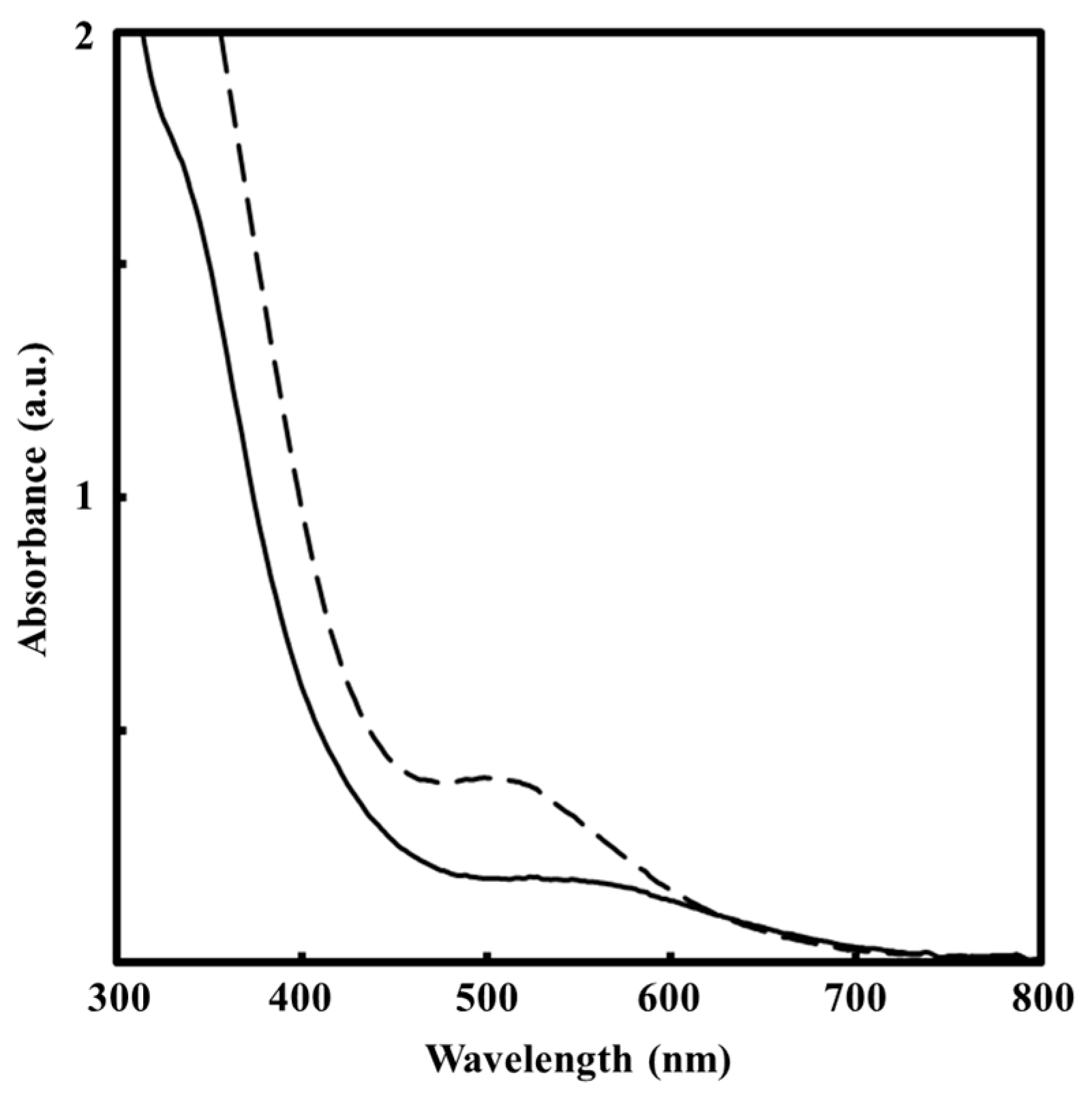
2.4.1. UV–Vis Absorption Spectra of Saq and SEtOH

The absorption spectra of two precursor solutions were measured in the range of 300 to 800 with a double beam mode, using a Hitachi U-2800 spectrophotometer (Hitachi, Tokyo, Japan). The final concentration of metal ions in the precursor solutions was adjusted to 4 μmol·g−1. Water and ethanol were used as the references for Saq and SEtOH, respectively.

2.4.2. Structural Characterization of the Thin Films

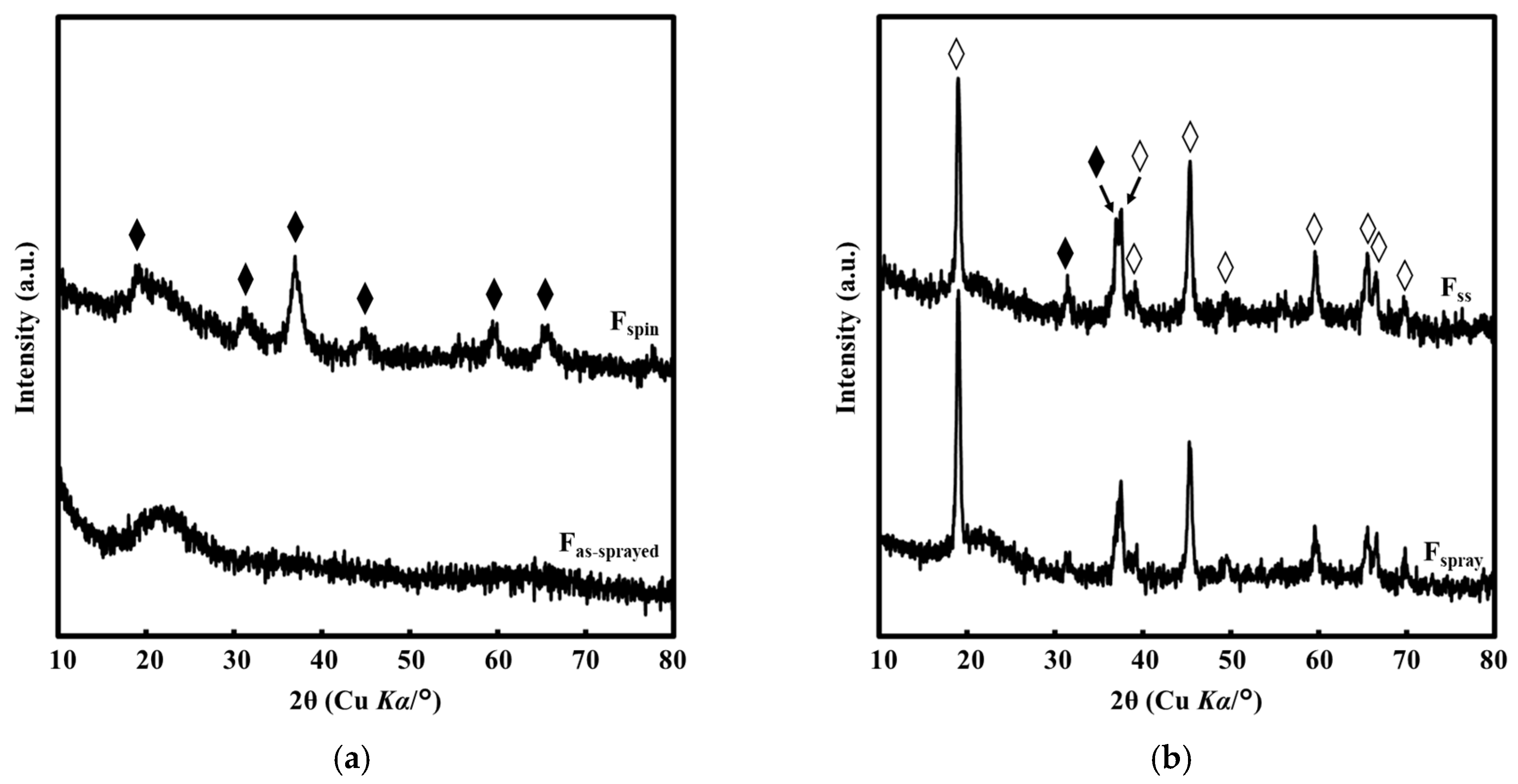
X-Ray Diffraction (XRD)
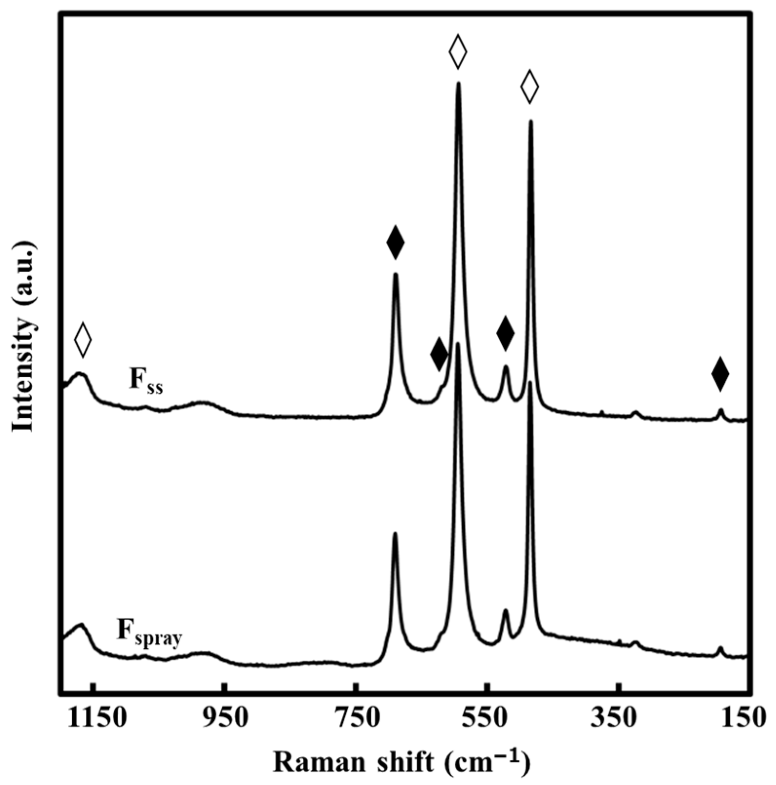
The crystal structures of all thin films were determined by means of XRD using a SmartLab X-ray diffractometer (Rigaku, Tokyo, Japan) with Cu Kα radiation source at a power of 45 kV and 200 mA. Parallel beam optics at an incidence angle 0.3° were used in the 2θ range of 10–80°, scanning at 0.05° step width and a speed of 5°·min−1.

Raman Spectroscopy

The Raman spectra of Fspray and Fss were measured at room temperature under dark conditions using the LaBRAM HR800 Raman microspectrometer (Horiba, Kyoto, Japan) with a charge coupled device (CCD) detector. An Nd:YAG laser (532 nm) was used as the excitation source, with an intensity of 10 mW and exposure time of 180 s. The spectra were measured in back-scattering geometry. The resolution was circa 1 cm−1 and the spot size of the laser light was 100 μm2. The content of Co3O4 in the Fspray and Fss films was determined using a calibration curve obtained from the peak area of the Raman spectrum for the mixture of pure LCO and Co3O4 crystal powders [21].

2.4.3. Surface Morphologies and Electrical Properties of Fspray and Fss

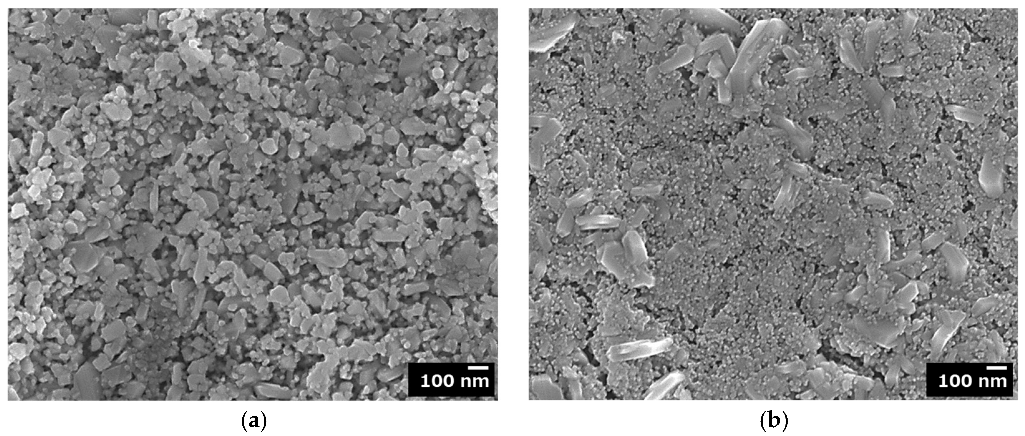
Field Emission Scanning Electron Microscopy (FE-SEM)

The surface morphologies of Fspray and Fss were observed by FE-SEM using a JSM-6701F (JEOL, Tokyo, Japan) at an accelerating voltage of 5 kV. The average grain sizes of the smallest observable grains on the FE-SEM image of Fspray and Fss were calculated from ten different grains, randomly selected on the FE-SEM image of the corresponding thin film.

Film Thickness and Hall Effect Measurements

The film thickness of Fspray and Fss was measured by a stylus profilometer (DEKTAK-3, Sloan Technology, Santa Barbara, CA, USA). Prior to coating, a portion of about 3 mm on the substrate edge was masked to leave an uncoated area. Thus, the thickness of Fspray and Fss was measured as the level difference between the uncoated part of the substrate and the thin film.
The electrical resistivity, carrier concentration, and carrier mobility of Fspray and Fss were measured at ambient temperature using an HL5500 Hall effect measurement system (Nanometrics, Milpitas, CA, USA) using a magnetic field of 0.517 T. The measurements were performed three times, and the average and standard deviation values were obtained.

3. Results

3.1. UV–Vis Absorption Spectra of Saq and SEtOH

The UV–Vis absorption spectra of the two precursor solutions are shown in Figure 1. The spectra of Saq and SEtOH show broad peaks at around 520 and 580 nm, respectively.

3.2. Structural Characterization of the Thin Films

3.2.1. XRD

The XRD patterns of all films obtained in the present study are shown in Figure 2. The XRD pattern of Fas-sprayed indicates that the film is amorphous (Figure 2a), because only a hollow band can be observed in the 2θ range of 15–35°. On the other hand, in the XRD pattern of Fspin, only peaks assignable to the (111), (220), (311), (400), (511), and (440) crystal phase of the Co3O4 appeared at 19.1°, 31.3°, 37.0°, 45.0°, 59.7°, and 65.3°, respectively (ICDD card No. 01-073-1701). Figure 2b shows the XRD patterns of Fspray and Fss. For both thin films, nine peaks at 19.0°, 37.4°, 39.3°, 45.2°, 49.5°, 59.6°, 65.6°, 66.6°, and 69.7° are assignable to the (003), (101), (012), (104), (015), (107), (018), (110), and (113) crystal phases of LCO, respectively (ICDD card No. 00-050-0653). In the identical patterns, the additional two peaks at 31.5° and 37.1° are assignable to the (220) and (311) crystal phases of the Co3O4, respectively (ICDD card No. 01-073-1701).

3.2.2. Raman Spectroscopy

The Raman spectra of Fspray and Fss are given in Figure 3. Two peaks at 485 and 595 cm−1 in both spectra are assignable to the LCO [3,25,26]. The additional broad peak at 1169 cm−1 is assignable to the overtone of the A1g mode of the LCO [27]. Four additional peaks assignable to the vibrational modes of Co3O4 are observed in both spectra at 194, 522, 619, and 690 cm−1 [28]. Using the calibration curve, the content of the Co3O4 phase in both thin films was determined to be less than 5 mol%.

3.3. Surface Morphologies and Electrical Properties of Fspray and Fss

The surface morphologies of Fspray and Fss are given in Figure 4. On the surface of Fspray, a plurality of uniformly distributed cylindrical grains up to circa 0.1 μm in size and smaller rounded grains with a minimum average grain size of 31 nm can be observed. The surface morphology of Fss reveals a combination of round grains with an average grain size of 18 nm, on top of extruding large and elongated grains circa 0.2 μm in length.
The thicknesses and electrical properties of Fspray and Fss are given in Table 1. The average values are given along with their corresponding standard deviations.

4. Discussion

4.1. Stable Aqueous Solution for LCO Thin Film Fabrication

Aqueous coating solutions containing lithium and cobalt acetates, nitrates, or hydroxides have been utilized in the preparation of gels [29] and LCO precipitates [30] in order to fabricate LCO thin films and powders. In those cases, the LCO phases were obtained after annealing at 550 °C for 10 h and 850 °C for 5 h, respectively. In the present study, an aqueous ammonia solution Saq containing both lithium and cobalt acetates was newly prepared and used to spray-coat onto a quartz glass preheated at 180 °C in air. The broad absorption peaks in the absorption spectra of Saq and SEtOH (Figure 1) are assignable to the d–d band of Co2+ complexes. The solution Saq was stable and could be easily used without forming any precipitate or clogging the nozzle of the airbrush. Additionally, the solution was suitable for coating a uniform precursor film onto a preheated quartz glass substrate with no powdery product. By heat treating the precursor film at 500 °C for 0.5 h, a thin film of LCO was easily obtained as the major product (Figure 2, Figure 3 and Figure 4a).
In addition, not only were the annealing conditions used in the present study lower in comparison to other studies available in the literature, but the LCO was easily fabricated on the quartz glass substrate. To the best of our knowledge, this is the first report on the fabrication of an LCO thin film on a quartz glass substrate by a wet chemical process.

4.2. Fabrication of LCO on Quartz Glass Substrate via Spray-Coating

It is generally suggested that the nature of the substrate is vital in determining the microstructure and surface morphology of the thin film deposited on the substrate [31]. For example, in the fabrication of LCO thin films by the sol-gel method, the annealing temperatures and heating times depend on the crystalline substrates, an Si substrate (800 °C, 0.5 h) or a (0001) oriented sapphire substrate (700 °C, 5 h) [9,10]. Very recently, it was clarified that an LCO thin film on a (0001) oriented sapphire substrate can be fabricated at a lower annealing temperature of 550 °C for 0.5 h via the MPM, in contrast to the sol-gel method [21]. The LCO formation at low annealing temperature in the MPM is attributable to the fast appearance of fine LCO crystals associated with the simultaneous nucleation of metal oxides and elimination of ligands during the heat treatment procedure [14,21], and is a vital benefit of the MPM over other wet chemical methods such as the sol-gel method.
It is important to note that in all of the previous studies employing wet chemical processes, crystalline substrates were used. In the present study, the LCO on a quartz glass substrate was fabricated by the spray-coating technique. It can be accepted that, during the spray-coating procedure with a preheated substrate in a temperature range of 150–180 °C, evaporation of the solvent in the vicinity of the hot substrate is accompanied by the formation of very fine, rigid, and concentrated precursors with the Li/Co ratio of LCO. The layer-by-layer accumulation of these LCO precursors continues during the subsequent spraying cycles, thus forming an amorphous precursor film on the quartz substrate. In fact, the Fas-sprayed film before the heat treatment at 500 °C showed no peak in its XRD pattern (Figure 2a). This accumulation process of the LCO precursor film by low-temperature spray-coating can prevent undesirable reactions between Li+ ion and the quartz glass substrate, because the precursor film spin-coated with SEtOH cannot be converted to the LCO film due to the reaction of Li+ ion with the quartz glass, leading to the formation of a film with Co3O4 crystal phase only, as shown by the XRD pattern of Fspin in Figure 2a.
The evaporation of solvent and deposition of fine and dry precursors make up the basic mechanism of the spray-deposition method [22,32]. In the case of molecular precursor solutions involving metal complexes, the accompanying elimination of ligands, ammonia in this case, plays an important role in forming amorphous precursor films of the desired compound, LCO, in the Li/Co ratio of 1. Therefore, heat treating at 500 °C for 0.5 h readily transforms the amorphous LCO phase into the LCO one, without a detectable presence of the low-temperature spinel-type LCO (Figure 3). In addition, the surface morphology of the resultant film (Figure 4a) shows grains formed on top of each other, with a minimum observable grain size of 31 nm. This is in agreement with the proposed formation of rigid and fine particles of amorphous LCO during the spray-coating procedure.

4.3. Versatility of MPM in Fabricating an Electrically Conductive Thin Film of LCO on a Quartz Glass Substrate

Generally, the electrical conductivity of LCO can be promoted by the diffusion of lithium ions. Although the results of the XRD and Raman measurements for the Fspray thin film reveal features attributable to the LCO, Hall effect measurements of this thin film were unsuccessful due to high electrical resistivity. This implies that the lithium ions in the matrix were immobile to ensure electrical conductivity, which was confirmed by the surface morphology of the thin film (Figure 4a) owing to the limited grain connection. The formation of LCO thin films on a crystalline substrate by annealing for a short duration at low annealing temperature was emphasized in our previous study [21]. In the present study, because a film of LCO had already formed on the quartz glass substrate during the heat treatment of the precursor film obtained via spray-coating, the heat treatment of a film spin-coated onto the Fspray film resulted in the nucleation of much smaller grains (18 nm) coexisting with the earlier formed grains, as observed from the surface morphology of the film (Figure 4b). As a result of improved grain connectivity, the lithium ions can diffuse easily within the matrix and the resultant thin film (Fss) is electrically conductive, with a carrier concentration and carrier mobility of 8(2) × 1016 cm−3 and 2(1) cm2·V−1·s−1, respectively. To confirm that the resultant electrical properties of the thin film Fss were a result of improved grain connectivity by the introduction of the smaller and well-connected grains, a thin film identical to Fspray was heat treated for a second time at 500 °C for 0.5 h. The twice heat-treated thin film was still not electrically conductive, and there was no significant change to the grain sizes as compared to the once heat treated Fspray. Although the Fss film consists of the Co3O4 phase (Figure 3), which may affect its electrical conductivity, the presence of an excess amount of Li+ ions in the matrix would lead to improved carrier mobility.
One of the many identified benefits of the MPM is the ability to prepare coating solutions ideal for various appropriate coating techniques. In the present study, it was clearly revealed how various coating techniques can be used in combination to successfully achieve fabrication of the desired functional thin film on a specific substrate.

5. Conclusions

The fabrication of a thin film of LCO on a quartz glass substrate was easily achieved at low temperature and with a short annealing duration. The spray-coating technique was useful in obtaining an intermediate thin film of LCO on the substrate after heat-treating the spray-coated precursor film at 500 °C for only 0.5 h. As a result, it was possible to form a thin film of LCO by spin-coating the precursor solution on top of the film obtained via spray-coating, and the Hall effect measurements of the resultant thin film were successful.
By combining the abovementioned processes, it was possible to control the formation of an LCO thin film on a quartz glass substrate. The present study serves as an indication that the spray-coating and spin-coating techniques can be effectively combined in the MPM to achieve the fabrication of desired functional thin films.

Author Contributions

Conceptualization, P.N.H., K.W., H.N. and M.S.; Methodology, P.N.H., K.W., H.N. and M.S.; Investigation, P.N.H., K.W.; Writing—Original Draft Preparation, P.N.H.; Writing—Review & Editing, P.N.H., H.N. and M.S.; Supervision, H.N. and M.S.

Funding

This work was funded by the Japan Society for the Promotion of Science (JSPS) KAKENHI Nos. 25410204 and 26810130. This work was also funded by the Japan Science and Technology Agency (JST) matching planner program No. 957483. This study was also financially supported by the international research project of Kogakuin University in collaboration with the National University of Singapore.

Conflicts of Interest

The authors declare no conflict of interest.

References

  1. Mizushima, K.; Jones, P.C.; Wiseman, P.J.; Goodenough, J.B. A new cathode material for batteries of high energy density. Mater. Res. Bull. 1980, 15, 783–789. [Google Scholar] [CrossRef]
  2. Nitta, N.; Wu, F.; Lee, J.T.; Yushin, G. Li-ion battery materials: Present and future. Mater. Today 2015, 18, 252–264. [Google Scholar] [CrossRef]
  3. Porthault, H.; Baddour-Hadjean, R.; Le Cras, F.; Bourbon, C.; Franger, S. Raman study of the spinel-to-layered phase transformation in sol-gel LiCoO2 cathode powders as a function of the post-annealing temperature. Vib. Spectrosc. 2012, 62, 152–158. [Google Scholar] [CrossRef]
  4. Mendiboure, A.; Delmas, C.; Hagenmuller, P. New layered structure obtained by electrochemical deintercalation of the metastable LiCoO2(O2) variety. Mater. Res. Bull. 1984, 19, 1383–1392. [Google Scholar] [CrossRef]
  5. Reimers, J.N.; Dahn, J.R. Electrochemical and in situ X-ray diffraction studies of lithium intercalation in LixCoO2. J. Electrochem. Soc. 1992, 139, 2091. [Google Scholar] [CrossRef]
  6. Bak, T.; Nowotny, J.; Rekas, M.; Sorrell, C.C.; Sugihara, S. Properties of the electrode material LixCoO2. Ionics (Kiel). 2000, 6, 92–106. [Google Scholar] [CrossRef]
  7. Trask, J.; Anapolsky, A.; Cardozo, B.; Januar, E.; Kumar, K.; Miller, M.; Brown, R.; Bhardwaj, R. Optimization of 10-μm, sputtered, LiCoO2 cathodes to enable higher energy density solid state batteries. J. Power Sources 2017, 350, 56–64. [Google Scholar] [CrossRef]
  8. Xia, H.; Lu, L.; Ceder, G. Li diffusion in LiCoO2 thin films prepared by pulsed laser deposition. J. Power Sources 2006, 159, 1422–1427. [Google Scholar] [CrossRef]
  9. Kushida, K.; Kuriyama, K. Sol–gel growth of LiCoO2 films on Si substrates by a spin-coating method. J. Cryst. Growth 2002, 237–239, 612–615. [Google Scholar] [CrossRef]
  10. Kwon, T.; Ohnishi, T.; Mitsuishi, K.; Ozawa, T.C.; Takada, K. Synthesis of LiCoO2 epitaxial thin films using a sol-gel method. J. Power Sources 2015, 274, 417–423. [Google Scholar] [CrossRef]
  11. Aziz, N.A.A.; Abdullah, T.K.; Mohamad, A.A. Synthesis of LiCoO2 prepared by sol–gel method. Procedia Chem. 2016, 19, 861–864. [Google Scholar] [CrossRef]
  12. Mizuno, Y.; Hosono, E.; Saito, T.; Okubo, M.; Nishio-Hamane, D.; Oh-Ishi, K.; Kudo, T.; Zhou, H. Electrospinning synthesis of wire-structured LiCoO2 for electrode materials of high-power li-ion batteries. J. Phys. Chem. C 2012, 116, 10774–10780. [Google Scholar] [CrossRef]
  13. Nagai, H.; Suzuki, T.; Takahashi, Y.; Sato, M. Photovoltaic lithium-ion battery fabricated by molecular precursor method. Funct. Mater. Lett. 2016, 9, 1650046. [Google Scholar] [CrossRef]
  14. Nagai, H.; Sato, M. Heat treatment in molecular precursor method for fabricating metal oxide thin films. In Heat Treatment—Conventional and Novel Applications; Czerwinski, F., Ed.; InTech: Rijeka, Croatia, 2012; pp. 297–322. [Google Scholar]
  15. Nagai, H.; Aoyama, S.; Hara, H. Photoluminescence and photoreactivity affected by oxygen defects in crystal-oriented rutile thin film fabricated by molecular precursor method. J. Mater. Sci. 2010, 45, 5704–5710. [Google Scholar] [CrossRef]
  16. Nagai, H.; Sato, M. Molecular precursor method for fabricating p-Type Cu2O and metallic Cu thin films. In Modern Technologies for Creating the Thin-film Systems and Coatings; Nikitenkov, N., Ed.; InTech: Rijeka, Croatia, 2017; pp. 3–20. [Google Scholar] [CrossRef]
  17. Nagai, H.; Mochizuki, C.; Hara, H.; Takano, I.; Sato, M. Enhanced UV-sensitivity of vis-responsive anatase thin films fabricated by using precursor solutions involving Ti complexes. Sol. Energy Mater. Sol. Cells 2008, 92, 1136–1144. [Google Scholar] [CrossRef]
  18. Likius, D.S.; Nagai, H.; Aoyama, S.; Mochizuki, C.; Hara, H.; Baba, N.; Sato, M. Percolation threshold for electrical resistivity of Ag-nanoparticle/titania composite thin films fabricated using molecular precursor method. J. Mater. Sci. 2012, 47, 3890–3899. [Google Scholar] [CrossRef]
  19. Nagai, H.; Mita, S.; Takano, I.; Honda, T.; Sato, M. Conductive and semi-transparent Cu thin film fabricated using molecular precursor solutions. Mater. Lett. 2015, 141, 235–237. [Google Scholar] [CrossRef]
  20. Nagai, H.; Suzuki, T.; Nakano, T.; Sato, M. Embedding of copper into submicrometer trenches in a silicon substrate using the molecular precursor solutions with copper. Mater. Lett. 2016, 182, 206–209. [Google Scholar] [CrossRef]
  21. Suzuki, T.; Nagai, H.; Lu, L.; Sato, M. Electrical properties of partially nitrided LiCoO2 thin films with an equivalent amount of Li and Co, involving small amounts of amorphous or crystallized Co3O4. Mater. Sci. Eng. B 2018, in press. [Google Scholar]
  22. Mochizuki, C.; Hara, H.; Takano, I.; Hayakawa, T.; Sato, M. Application of carbonated apatite coating on a Ti substrate by aqueous spray method. Mater. Sci. Eng. C 2013, 33, 951–958. [Google Scholar] [CrossRef]
  23. Hishimone, P.; Nagai, H.; Morita, M.; Sakamoto, T.; Sato, M. Highly-conductive and well-adhered Cu thin film fabricated on quartz glass by heat treatment of a precursor film obtained via spray-coating of an aqueous solution involving Cu(II) complexes. Coatings 2018, 8, 352. [Google Scholar] [CrossRef]
  24. Khim, D.; Baeg, K.; Yu, B.; Kang, S.; Kang, M. Spray-printed organic field-effect transistors and complementary inverters. J. Mater. Chem. C 2013, 1, 1500–1506. [Google Scholar] [CrossRef]
  25. Kosuril, Y.R.; Penki, T.R.; Nookala, M.M.; Morgen, P.; Gowravaram, M.R.; Rao Kosuri, Y.; Rao Penki, T.; Nookala, M.M.; Morgen, P.; Rao Gowravaram, M. Investigations on sputter deposited LiCoO2 thin films from powder target. Adv. Mater. Lett. 2013, 4, 615–620. [Google Scholar] [CrossRef]
  26. Inaba, M.; Todzuka, Y.; Yoshida, H.; Grincourt, Y.; Tasaka, A.; Tomida, Y.; Ogumi, Z. Raman spectra of LiCo1−yNiyO2. Chem. Lett. 1995, 24, 889–890. [Google Scholar] [CrossRef]
  27. Gross, T.; Hess, C. Raman diagnostics of LiCoO2 electrodes for lithium-ion batteries. J. Power Sources 2014, 256, 220–225. [Google Scholar] [CrossRef]
  28. Hadjiev, V.G.; Iliev, M.N.; Vergilov, I.V. The Raman spectra of Co3O4. J. Phys. C Solid State Phys. 1988, 21, L199–L201. [Google Scholar] [CrossRef]
  29. Peng, Z.; Wan, C.; Jiang, C. Synthesis by sol–gel process and characterization of LiCoO2 cathode materials. J. Power Sources 1998, 72, 215–220. [Google Scholar] [CrossRef]
  30. Liao, D.Q.; Xi, X.M. Study on the preparation of LiCoO2 by multiphase redox method. Powder Technol. 2014, 253, 146–151. [Google Scholar] [CrossRef]
  31. Lee, J.K.; Lee, S.J.; Baik, H.K.; Lee, H.Y.; Jang, S.W.; Lee, S.M. Substrate effect on the microstructure and electrochemical properties in the deposition of a thin film LiCoO2 electrode. Electrochem. Solid State Lett. 1999, 2, 512–515. [Google Scholar] [CrossRef]
  32. Hsu, H.-W.; Liu, C.-L. Spray-coating semiconducting conjugated polymers for organic thin film transistor applications. RSC Adv. 2014, 4, 30145–30149. [Google Scholar] [CrossRef]
Figure 1. Absorption spectra of Saq (dashed line) and SEtOH (solid line).
Coatings 09 00097 g001
Figure 2. (a) X-ray diffraction (XRD) patterns of Fas-sprayed and Fspin. (b) XRD patterns of Fspray and Fss. Peaks assignable to LCO and Co3O4 are denoted by ♢ and ♦, respectively.
Coatings 09 00097 g002
Figure 3. Raman spectra of Fspray and Fss. Peaks assignable to the vibration modes for LCO and Co3O4 are represented by ♢ and ♦, respectively.
Coatings 09 00097 g003
Figure 4. Field electron scanning electron microscope (FE-SEM) images showing surface morphologies of (a) Fspray and (b) Fss.
Coatings 09 00097 g004
Table 1. Thickness and electrical resistivity, carrier concentration, and carrier mobility of Fspray and Fss.
Thin FilmThickness
(nm)
Electrical Resistivity
(Ω·cm)
Carrier Concentration
(cm−3)
Carrier Mobility
(cm2·V−1·s−1)
Fspray120>3 × 10⁶
Fss21035(2)8(2) × 10162(1)
Standard deviations are given in parentheses (n = 3).

