Article

Nonuniform Distribution of Crystalline Phases and Grain Sizes in the Surface Layers of WC Ceramics Produced by Spark Plasma Sintering

by
Ksenia E. Smetanina
1,*,
Pavel V. Andreev
1,*,
Evgeny A. Lantsev
1,
Aleksey V. Nokhrin
1,
Artem A. Murashov
1,
Natalia V. Isaeva
1,2,
Yury V. Blagoveshchensky
2,
Maksim S. Boldin
1 and
Vladimir N. Chuvil’deev
1
1
Materials Science Department, Research Institute of Physics and Technology, Lobachevsky State University of Nizhny Novgorod, 603022 Nizhny Novgorod, Russia
2
Laboratory of Plasma Processes in Metallurgy and Metal Processing, A.A. Baykov Institute of Metallurgy and Materials Science, Russian Academy of Sciences, 119334 Moscow, Russia
*
Authors to whom correspondence should be addressed.
Coatings 2023, 13(6), 1051; https://doi.org/10.3390/coatings13061051
Submission received: 15 May 2023 / Revised: 1 June 2023 / Accepted: 5 June 2023 / Published: 6 June 2023
(This article belongs to the Special Issue Trends in Spark Plasma Sintering of Advanced Materials)

Abstract

:
The research results conducted on binderless tungsten carbide (WC) ceramics obtained by spark plasma sintering (SPS) of WC powders with different average particle sizes (95, 800, 3000 nm) are presented. Nonuniform distribution of crystalline phases and microstructure of the WC ceramics was studied using layer-by-layer X-ray diffraction (XRD) analysis and scanning electron microscopy (SEM). Surface layers of the WC-based ceramics are characterized by nonuniform distribution of W2C crystalline phase and grain sizes, including the appearance of abnormally large grains. Thickness of the nonuniform layer was at least 50 μm. The effect under study is associated with an intense carbon diffusion from graphite foil. On the one hand, this contributed to a decrease in the intensity of W2C phase particle formation, which is transformed into α-WC phase due to the carbon. On the other hand, it caused abnormal grain growth in the layer where the carbon diffused. The obtained value of the carbon diffusion depth (50 μm) exceeds the values known from the literature (up to 1 μm in the case of volume diffusion even at temperature of 2370 °C and exposure time of ~60 h). The use of boron nitride (BN) as a protective coating on graphite mold parts did not prevent the formation of nonuniform layer on the ceramic surface.

1. Introduction

Hard alloys based on tungsten carbide (WC) with the addition of cobalt (Co), iron (Fe), nickel (Ni) and other low-melting metal phases are used in mechanical engineering for the production of wire drawing dies, drill bits and other wear-resistant machine elements [1,2,3,4]. Tungsten carbide is characterized by high hardness and wear resistance, high melting point as well as chemical resistance to acids and alkalis [1,5]. The combination of these properties allows the use of WC-based ceramics at high temperatures and under heavy loads. However, binderless tungsten carbide has a low fracture toughness and bending strength [5]. New technologies for producing high-strength binderless WC ceramics attract researchers’ attention for this reason [5,6,7,8].
Spark plasma sintering (SPS) is one of the most promising FAST (field-assisted sintering technology) methods of manufacturing high-density fine-grained ceramics and hard alloys [3,4,5,9,10]. The technology consists of high-speed heating of conductive mold filled with initial powder or green body by passing millisecond current pulses (up to 5000 A) with simultaneous application of uniaxial load [9,11,12,13]. High speed of heating (up 2500 °C/min) is provided by the use of pulse mode. This approach makes it possible to reduce the sintering time and keep the grain size in ceramics close to the particle size of initial powder. The advantage of SPS is the ability to control and manage key technological parameters directly during the sintering process—the applied stress, the heating rate, the sintering temperature, the time of isothermal exposure, the cooling rate. This ensures effective control of microstructure parameters and performance properties of ceramics and hard alloys. Descriptions of the SPS features were considered in detail in previous studies [11,12,13]. The effectiveness of SPS technology use for sintering ceramics and hard alloys based on tungsten carbide was demonstrated in several studies [3,4,5,10].
The use of WC nanopowders for the production of ceramics and hard alloys provides additional opportunities to optimize their phase composition, microstructure parameters and improve mechanical properties. One of the most promising methods for producing WC nanopowders is the DC arc plasma chemical synthesis [14]. The method allows to obtain tungsten monocarbide (α-WC) powders with an average particle size of 30–80 nm. Previous studies reported that binderless ceramics obtained by SPS of plasma chemical nanopowders WC are characterized by high hardness (up to 30 GPa) and fracture toughness (4–5 MPa m1/2) [5]. WC—Co hard alloys made by sintering of plasma chemical nanopowders WC also had high hardness [15].
Recent studies suggest that ceramics and hard alloys produced by spark plasma sintering of WC nanopowders have nonuniform microstructure [15,16,17]. The method of layer-by-layer X-ray diffraction analysis (XRD) is the most effective way to study this issue [16,17]. The XRD information depth is about 5 μm at the CuKα wavelength (λ = 1.54 Å) due to the high absorption of X-ray radiation in phases containing tungsten. Sequential removal of layers will allow to carry out phase analysis of ceramics at different distances from the surface. The distribution of η-phase (Co3W3C) over the depth of WC + 10% wt. Co hard alloys was investigated using the technique of layer-by-layer XRD. It was found that there is no η-phase (Co3W3C) in the surface layer about 300–350 μm in thickness [17]. Similar results were obtained for binderless WC ceramics [16]. It is assumed that the surface layer heterogeneity of ceramics and hard alloys based on WC was due to the intense carbon diffusion from graphite foil and graphite mold used in spark plasma sintering [16,17]. The carbon contamination effect of the surface layers of ceramics during SPS was also described in several studies [12,18,19,20].
The carbon contamination is considered as a negative effect that affects many characteristics of different ceramics [12,19,20,21,22,23]. As a result of this effect, the optical properties of oxide ceramics can be reduced [20,21,22,23]. At the same time, carburization of the surface layers in ceramics and hard alloys based on WC can lead to a decrease in the content of undesirable phases and, as a result, contribute to an increase in hardness [17,24].
W–C system is characterized by the presence of a very narrow range of temperatures and concentrations corresponding to the area of stable existence of α-WC phase [25]. Even a slight deviation of the carbon content from the stoichiometric composition (6.13% wt.) leads to the appearance of undesirable W2C phase in WC ceramics or to the formation of η-phases (Co2W4C, Co3W3C, Co6W6C, Co3W9C4) in WC–Co hard alloys [5,15,17,25].
Adsorbed oxygen is present on the surface of WC powder particles [26]. Tungsten carbide nanopowders are characterized by increased oxygen concentration [26,27]. Oxygen reacts with carbon in carbide particles to form carbon dioxide, W2C phase and/or tungsten oxide in the process of heating WC powder [27]. The problem of decarbonization is partially solved by introducing a small amount of graphite into the raw WC powder [15,17,27]. Carbon is also introduced into tungsten powders containing oxygen as an impurity [28,29]. This decision avoids the formation of undesirable phases and leads to an increase in the mechanical properties of ceramics and hard alloys. However, excessive graphite content in the raw WC powder can lead to rapid grain growth and negatively affects the mechanical properties of WC-based materials [5,15,17,30,31]. The exact determination of the required graphite content is a difficult task. The oxygen concentration may increase during long-term storage of the powder or working with it in an environment containing oxygen.
The purpose of the work is a detailed study of the heterogeneity of the surface layers of the binderless tungsten carbide ceramics produced by spark plasma sintering.

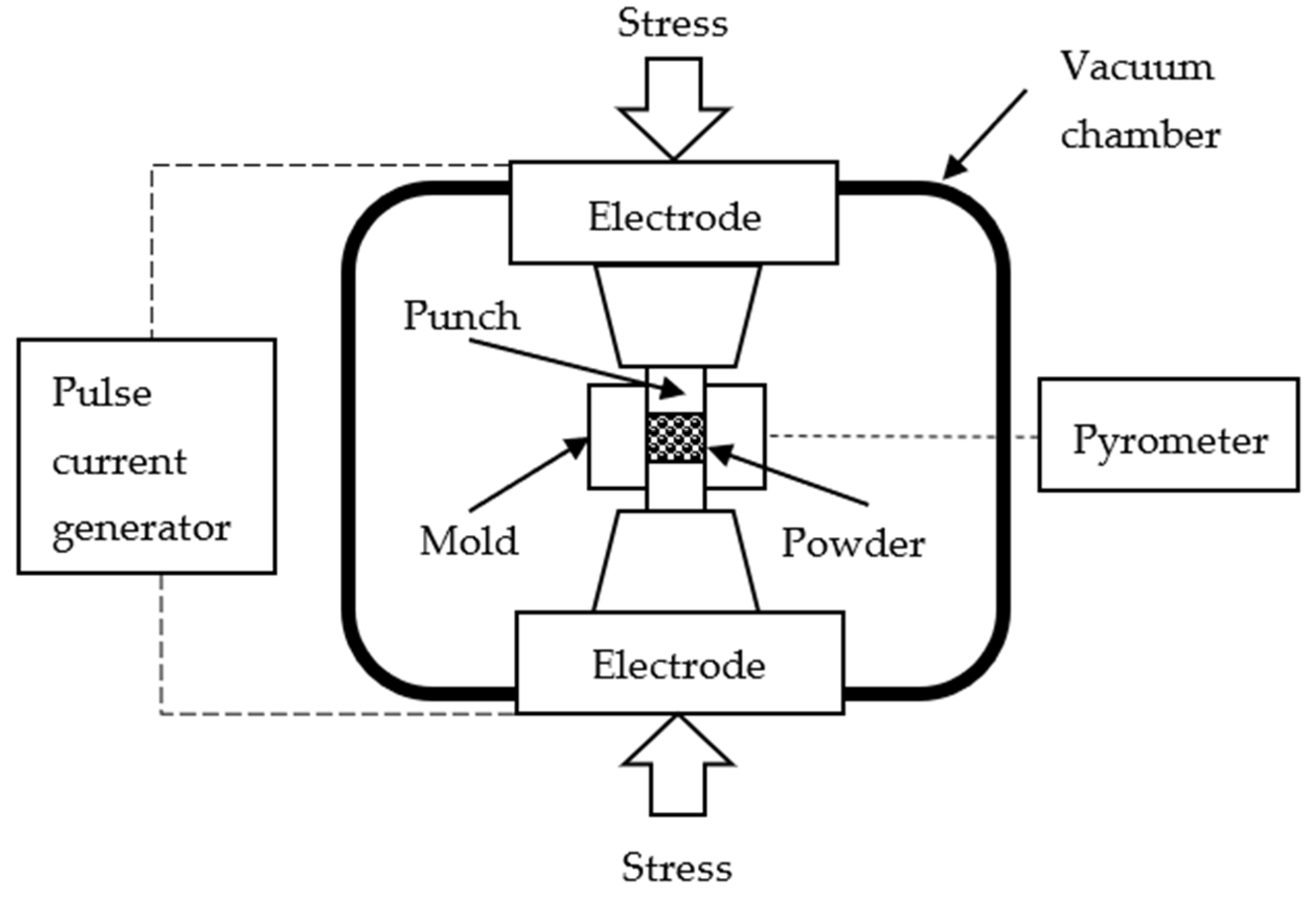
2. Materials and Methods

Three tungsten carbide (WC) powders with different average particle sizes were used as raw materials. Nanopowder #1 was prepared by DC arc plasma chemical synthesis [14]. Powders #2 and #3 were industrial micron powders produced by Kirovgrad Plant of Hard Alloys, JSC (Kirovgrad, Russia). Carbon and oxygen content in the raw powders was determined using an analyzer CS 400 (LECO, MI, USA). The average particle size of the powders was estimated by the formula: R0 = 6/ρthSBET, where ρth is the theoretical density of α–WC (15.68 g/m3), SBET is the specific surface area of the powder particles obtained by the BET method using TriStar 3000 analyzer (Micromeritics Instrument Corporation, GA, USA). The characteristics of the WC powders are presented in Table 1.
The concentration of oxygen in Nanopowder #1 was elevated. Carbon was added in the form of graphite (0.3% wt.) by the manufacturer to the composition of powder #1 to eliminate the negative effects of oxygen. Powders #2 and #3 also contained 0.05% wt. of graphite.
The powders were poured into a graphite mold with an inner diameter of 12.8 mm, an outer diameter of 30 mm and a height of 30 mm. The uniaxial stress (70 MPa) was applied to the mold using two graphite punches. The punch diameter was 12 mm and the height was 20 mm. Graphite foil with a thickness of 200 μm was used to reduce the clearance between the specimen and the inner surface of the mold. Two sheets of graphite foil were placed between the powder and the punch surface. Preliminary pressing of the powders in mold was carried out using a hydraulic press Sorokin (Sorokin, Moscow, Russia) at room temperature at a stress of 70 MPa.
Spark plasma sintering of the WC powders was conducted using Dr. Sinter model SPS-625 setup (SPS Syntex, Tokyo, Japan). Figure 1 shows schematic setup of SPS system.
Graphite mold was covered with graphite felt of 4 mm in thickness to ensure the homogeneity of the temperature field during sintering inside the mold. A hole with a diameter of 14 mm was cut into the graphite felt for the temperature control during SPS. The temperature was measured using an optical pyrometer IR-AHS2 (CHINO, Tokyo, Japan) focused on the height middle of the mold outer wall. The accuracy of temperature measurements was ±20 °C. SPS of the WC powders was carried out in a vacuum (about 6 Pa) under a uniaxial compressive stress of 70 MPa. The powders were heated at the rate of 50 °C/min until the end temperature of the effective shrinkage of the powders: 1410 °C (powder #1), 1530 °C (powder #2), 1625 °C (powder #3). There was no exposure at the sintering temperature. Free cooling was used to cool the specimens.
The comparison objects were WC ceramics produced by sintering in graphite molds with a protective coating of boron nitride (BN). Solution of BN was applied to the inner surfaces of the graphite parts (mold, punches, foil) that contact with the powder during SPS.
The dependencies of the effective powder shrinkage (Leff) on the heating temperature were recorded during sintering using a built-in dilatometer of Dr. Sinter model SPS-625. Experiments on heating an empty mold were carried out to account for the contribution of thermal expansion of the graphite mold (L0). The true shrinkage (L) was determined by the formula: L = LeffL0.
The initial heights of the ceramics did not exceed 6 mm. The specimen surface was sequentially ground with diamond discs and polished with diamond pastes. Grinding was carried out on the Secotom 10 machine (Struers, Copenhagen, Denmark). Polishing was performed on the AutoMet 250 machine (Buehler, Braunschweig, Germany). Eleven stages of the mechanical treatment of the specimen surface were carried out. Each stage consisted of grinding and polishing. The layer up to 50 µm in thickness (stages #1–7) and the layer at least 200 µm in thickness (stages #8–11) was removed from the specimen surface in each treatment stage. In total, the layer about 1100–1200 μm in thickness was removed from the surface of each specimen. The height control of the specimens was carried out using a micrometer 34480-25_z01 (ZUBR, Moscow, Russia) with an accuracy equal to 10 μm.
X-ray diffraction (XRD) studies of the powders and ceramics were carried out on the XRD-7000 diffractometer (Shimadzu, Kyoto, Japan) in CuKα radiation (λ = 1.54 Å). Scanning was performed in the Bragg–Brentano geometry in the range of angles 2θ = 30–80° with the step of 0.04° and the exposure of 2 s. XRD experiments were carried out after each stage of the specimen surface treatment (stages #1–11). The XRD experiment of stage #0 was conducted before the mechanical treatment of the specimen surface. The calculated penetration depth of CuKα radiation into the surface of WC specimens did not exceed 5 µm, which was much less than the thickness of the removed layer during the mechanical grinding (50–200 µm). Qualitative phase analysis was carried out using the PDF-2 database (ICDD, 2012): α-WC (PDF 00-051-0939), W2C (PDF 00-035-0776), W (PDF 00-004-0806), C (PDF 00-056-0159), WB (PDF 00-006-0541), BN (PDF 01-085-1068). Quantitative phase analysis was carried out by the reference ratio method using cif-files of the ICSD (2015): α-WC (ICSD 43380), W2C (ICSD 159904), W (ICSD 76151). The diffraction peak (101) at 2θ = 48.3° was chosen as the analytical peak of α-WC phase during the quantitative analysis. The analytical peaks of W2C and W phases were (101) at 2θ = 39.6° and (110) at 2θ = 40.3°, respectively.
The microstructure of the powders and ceramics was studied by scanning electron microscopy (SEM) on a microscope JSM-6490 (JEOL, Tokyo, Japan). The images of the powder microstructure were obtained in secondary electron imaging (SEI) mode, which is sensitive to the surface relief of the powder particles. The images of the ceramic microstructure were obtained in back-scattered electron contrast (BEC) mode, which is sensitive to contrast. After the sixth stage of the mechanical treatment of the surface and removal of the layer of 150 µm in thickness, the control specimens were cut in half, as shown in Figure 2a. The cross section was polished with diamond pastes. Figure 2b shows the areas under study. In particular, D area was located on the surface that was subjected to the mechanical treatment.
In total, 9 ceramic specimens were sintered and studied. Powders #2 and #3 were sintered twice to control the reproducibility of the measurement results.
Specimens produced from powders #1, #2, #3 are referred to as ceramics #1, #2, #3. Specimen labeling Ceramic 2-1 means that the specimen #1 produced from powder #2 is described. Specimen labeling Ceramic 2-1-BN means that the specimen #1 produced from powder #2 using a protective coating of boron nitride is described. Such labeling of the specimens was used to demonstrate the reproducibility of the results. The result reproducibility was evaluated based on a comparison of the specimens sintered under the same conditions.

3. Results

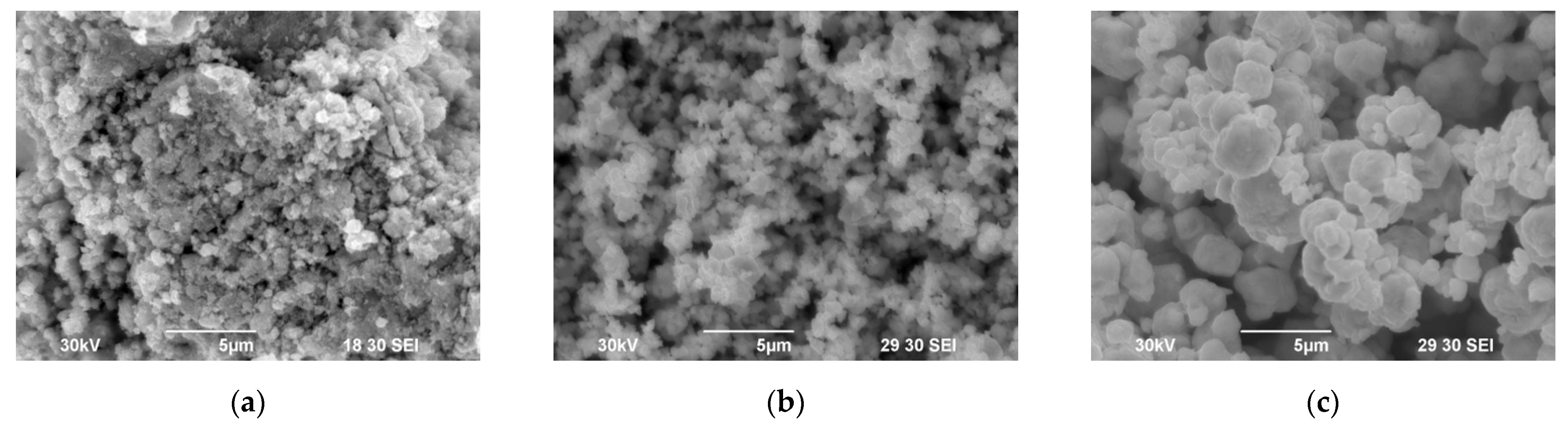
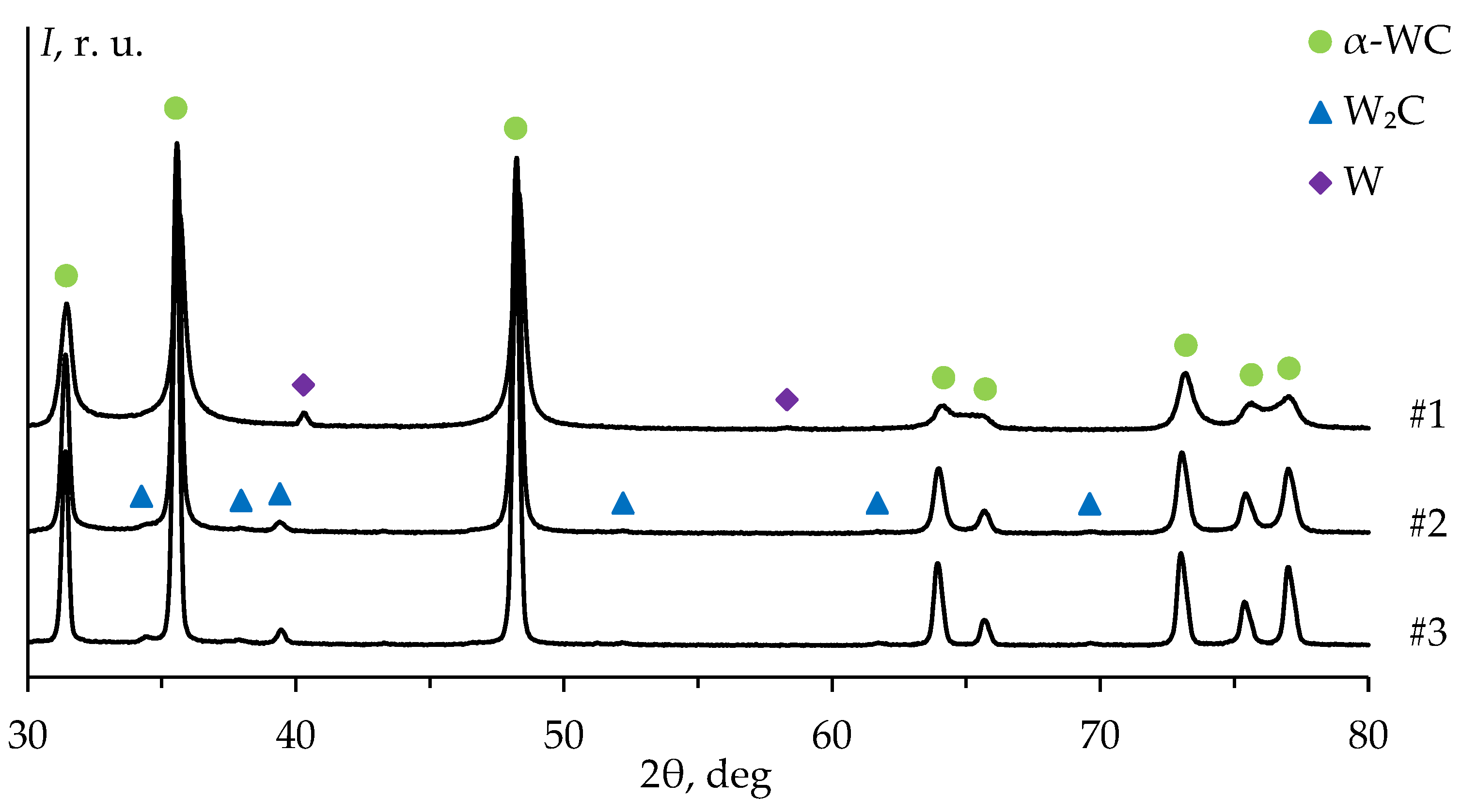
3.1. Characterization of the WC Powders

Figure 3 shows the results of the SEM studies of the WC initial powders. Agglomerates of individual nanoparticles were observed in powder #1 (Figure 3a). The size of the agglomerates did not exceed 10 μm. No agglomerates were found in powders #2 and #3 (Figure 3b,c). The average particle size of powders #2 and #3 was 1 μm and 3 μm, respectively. The specified values of the average particle size determined by the chord method were close to the average particle size according to Fischer, declared by the powder manufacturer (Table 1).
Figure 4 presents the results of the XRD studies of the WC powders. The diffraction peaks on the pattern of powder #1 corresponded to α-WC and α-W phases. The XRD peaks on the diffraction pattern of powder #1 were significantly broadened compared to the XRD peaks on the patterns of powders #2 and #3. The mass fraction of tungsten in plasma chemical nanopowder #1 was 2.6 ± 0.2% wt. (Table 1). The XRD peaks on the patterns of powders #2 and #3 corresponded to α-WC and W2C phases. The mass fraction of W2C in powders #2 and #3 were 1.4 ± 0.2 and 1.6 ± 0.2% wt., respectively (Table 1).

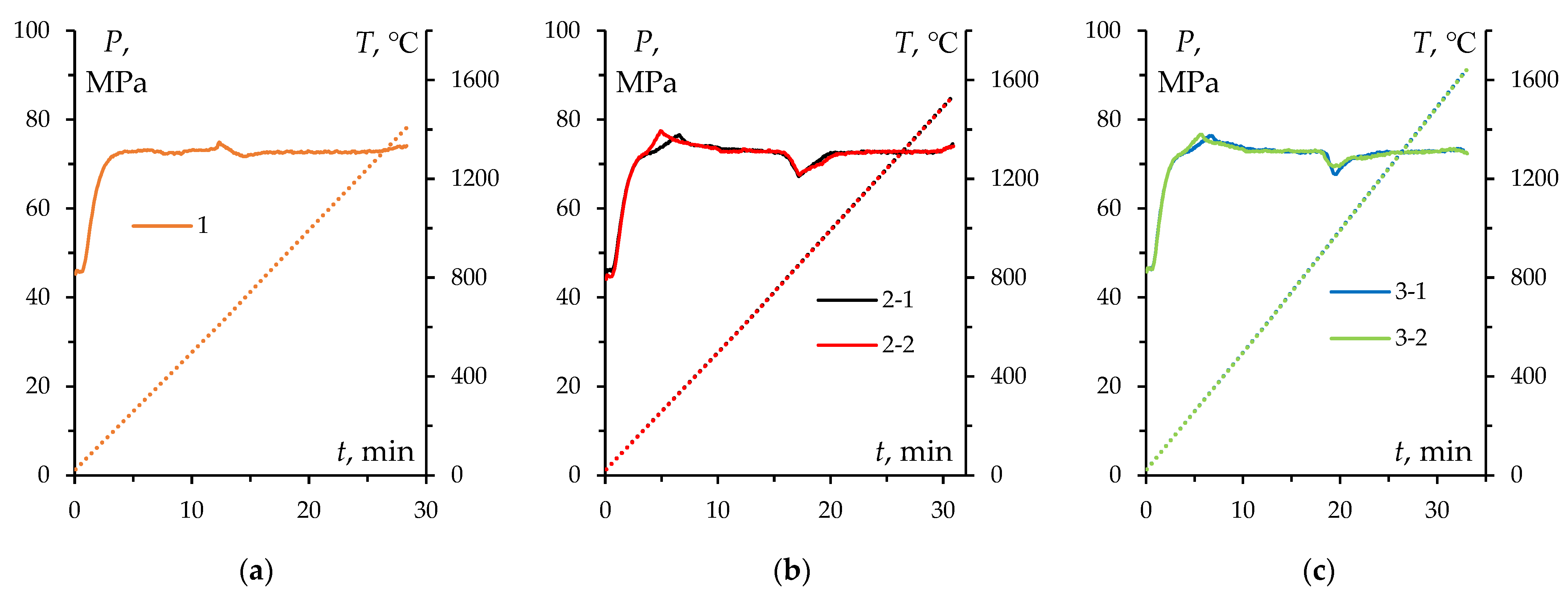
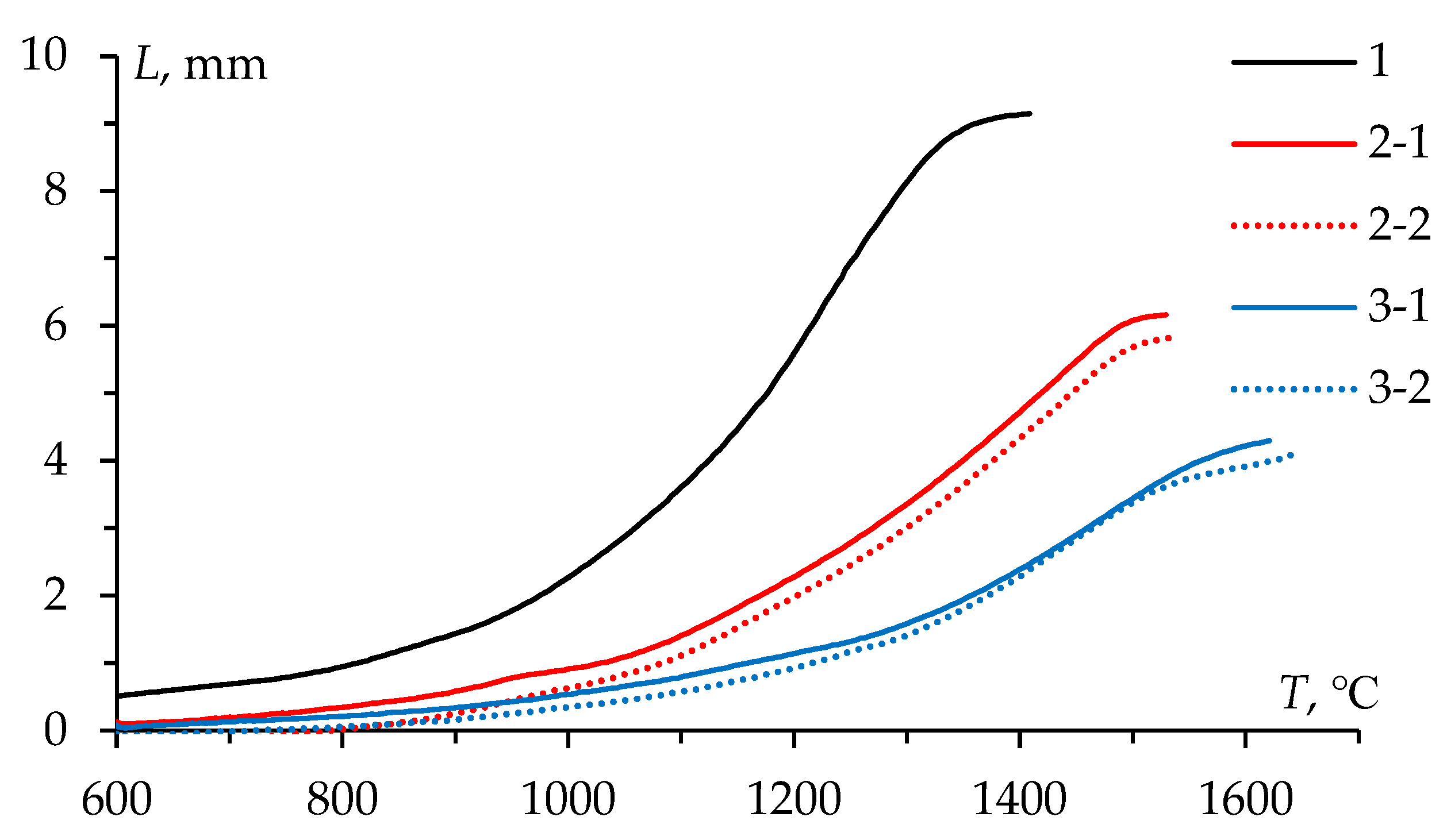
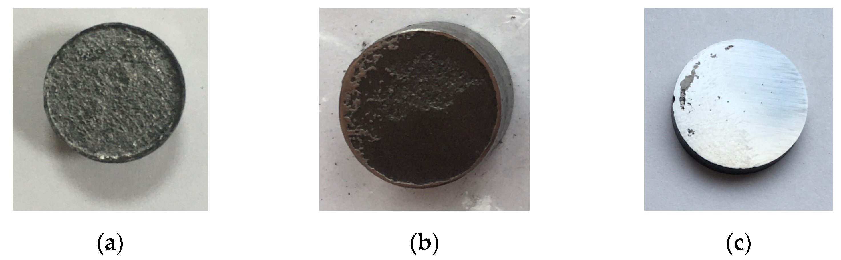
3.2. SPS of the WC Powders

Figure 5 shows graphical sintering diagrams of the ceramics sintered from powders #1-3 in the Process time (t)—Temperature (T)—Stress (P) coordinates. Stability and reproducibility of SPS process were ensured during the manufacture of specimens #2 and #3 (Figure 5b,c).
Figure 6 presents the temperature shrinkage curves L(T) of the WC powders. The L(T) curves had a conventional three-stage character for all powders: stage I—slight compaction at 600–1000 °C, stage II—intensive shrinkage at 1000–1400 °C, stage III—low shrinkage rate at above 1400 °C. The difference in the absolute shrinkage (Lmax) observed in Figure 6 was due to the difference in the bulk density of the powders under study. A previous investigation reported a detailed analysis of SPS process of these powders [15].
The effective density of ceramics #1, #2, #3 was determined by hydrostatic weighing: 99.2% (15.642 g/cm3), 96.2% (15.168 g/cm3), 96.0% (15.140 g/cm3), respectively [15]. The specimens had no visible macrodefects such as chips, cracks or large pores. The specimens were not destroyed during the grinding and polishing process.

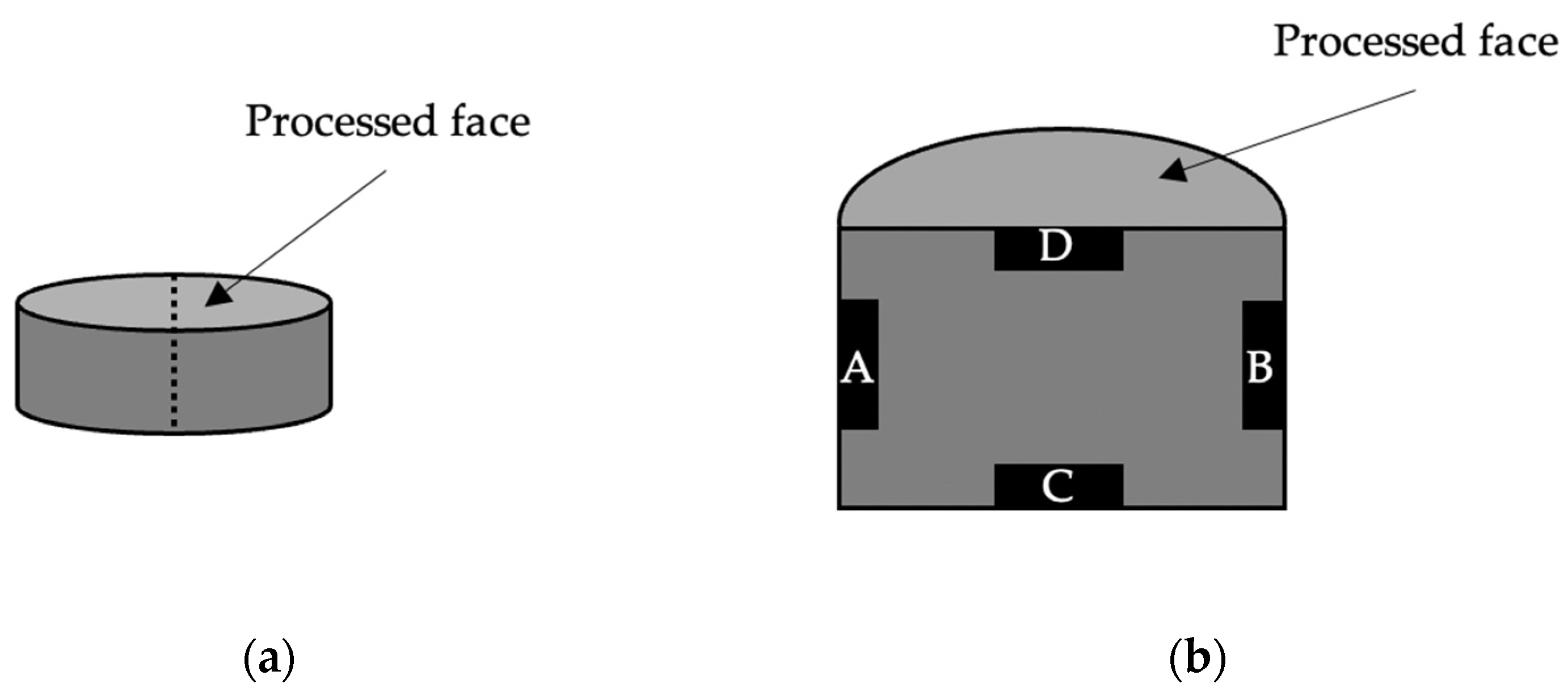
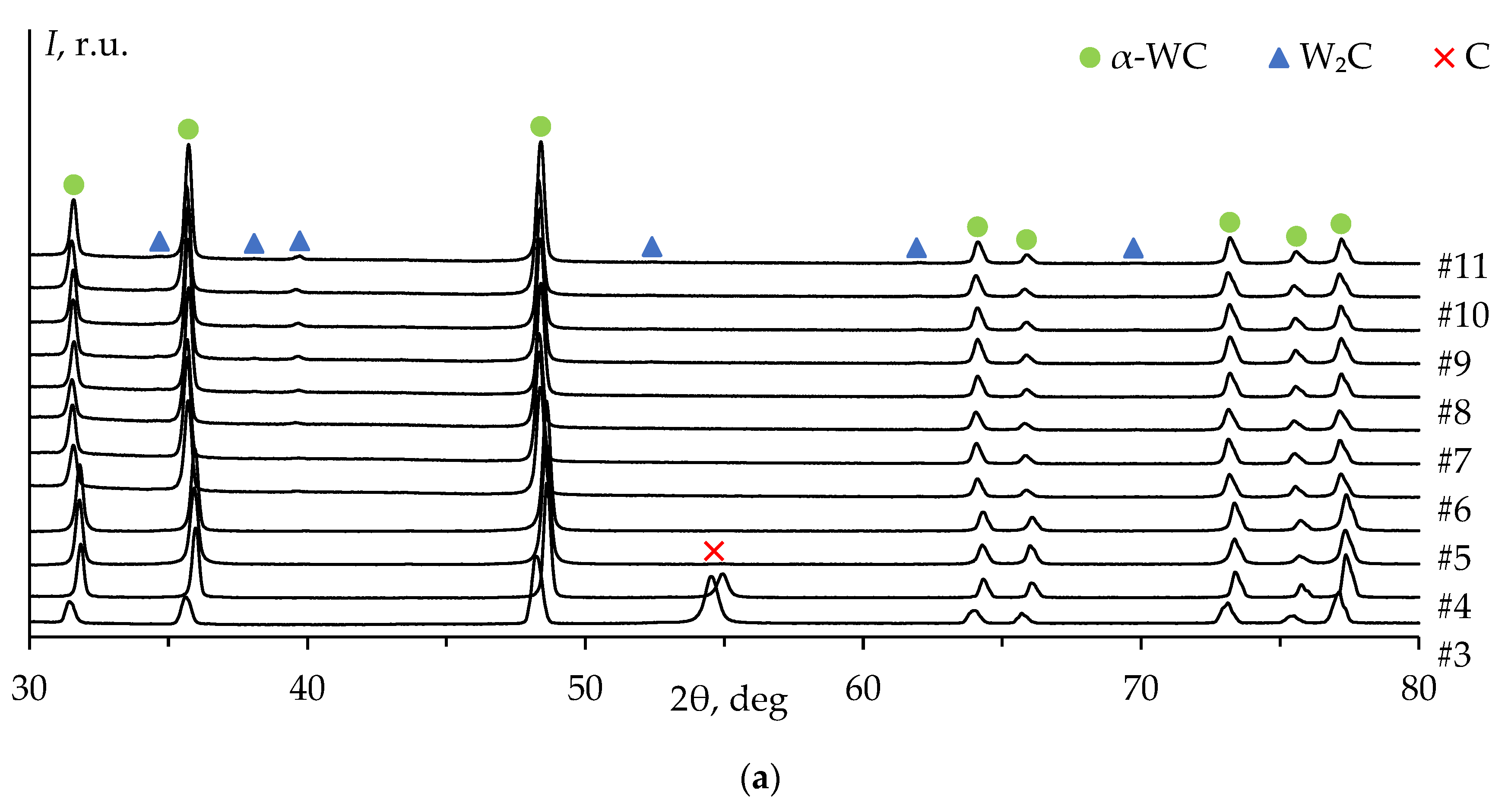
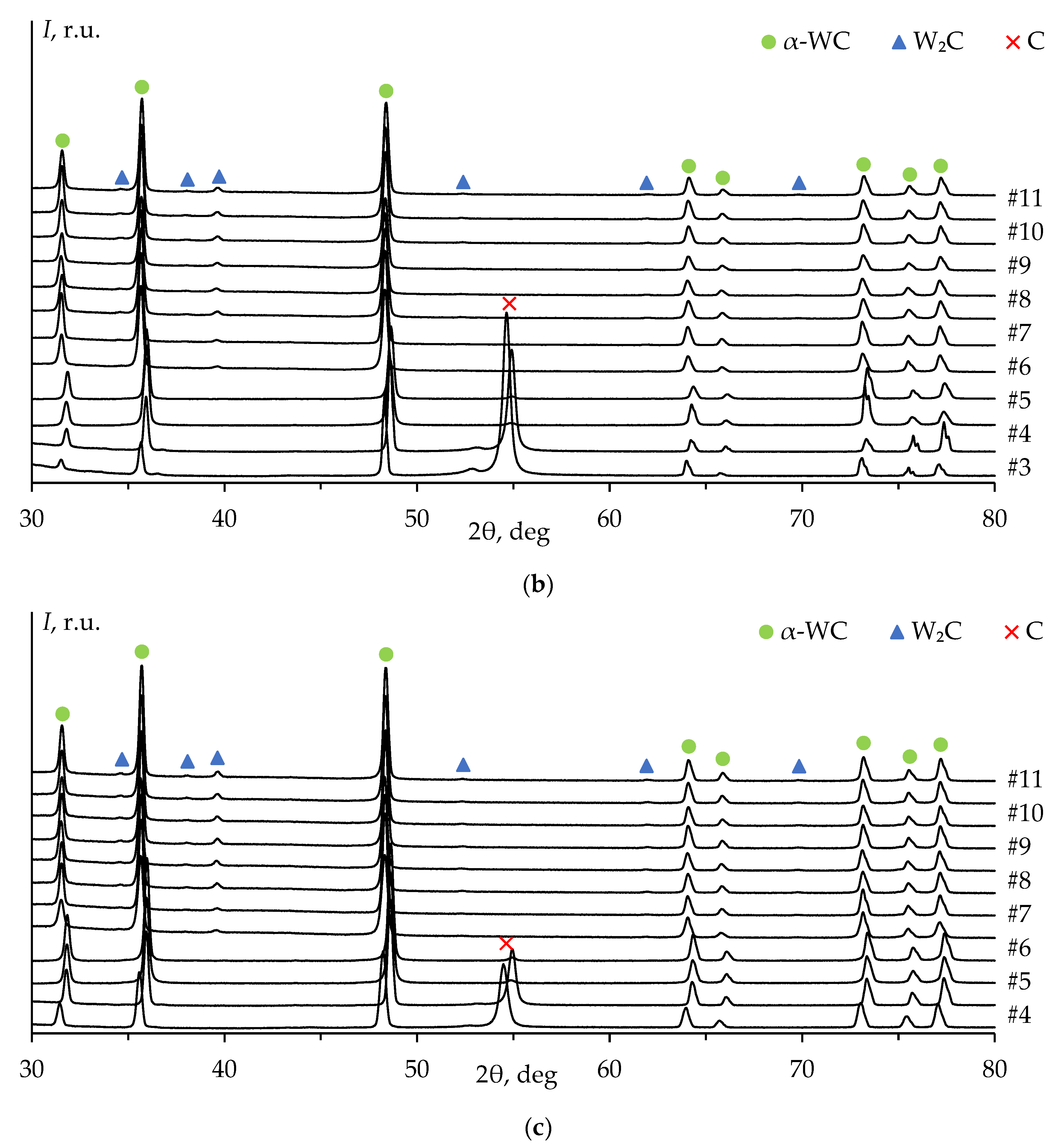
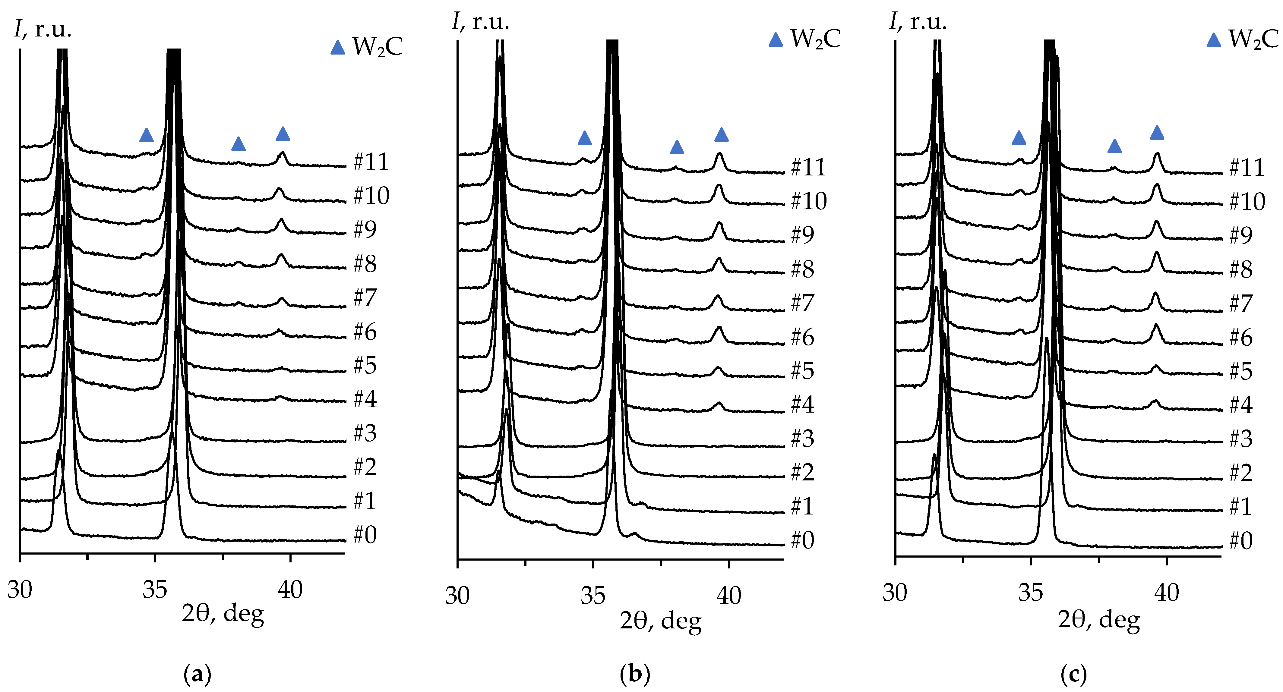
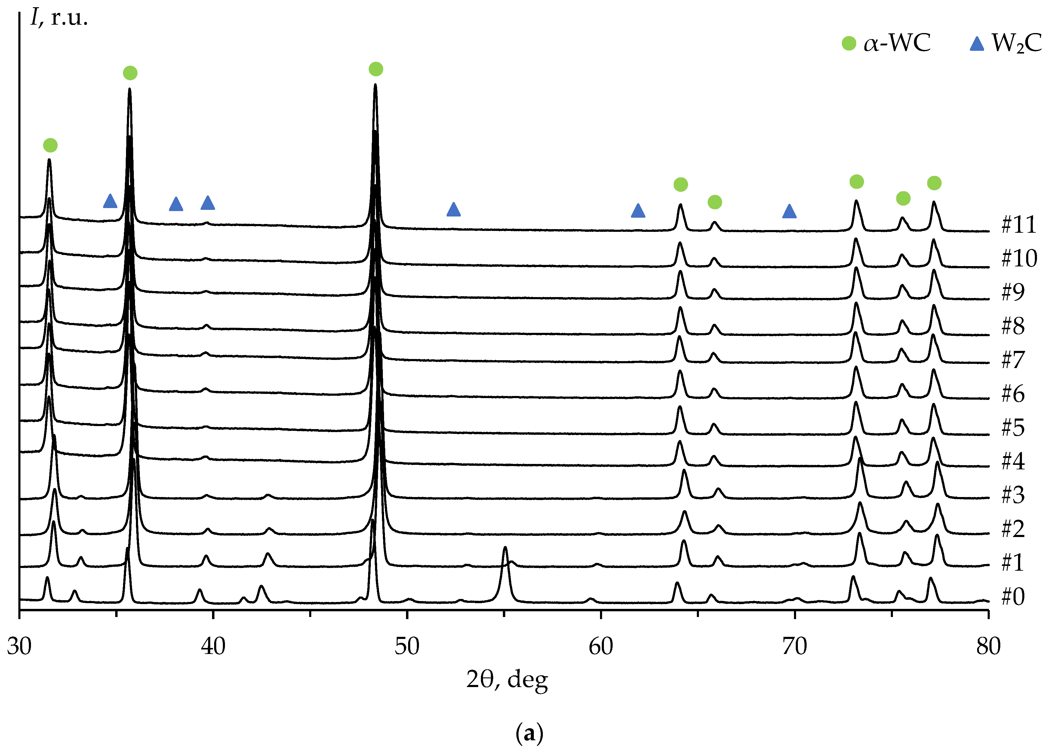
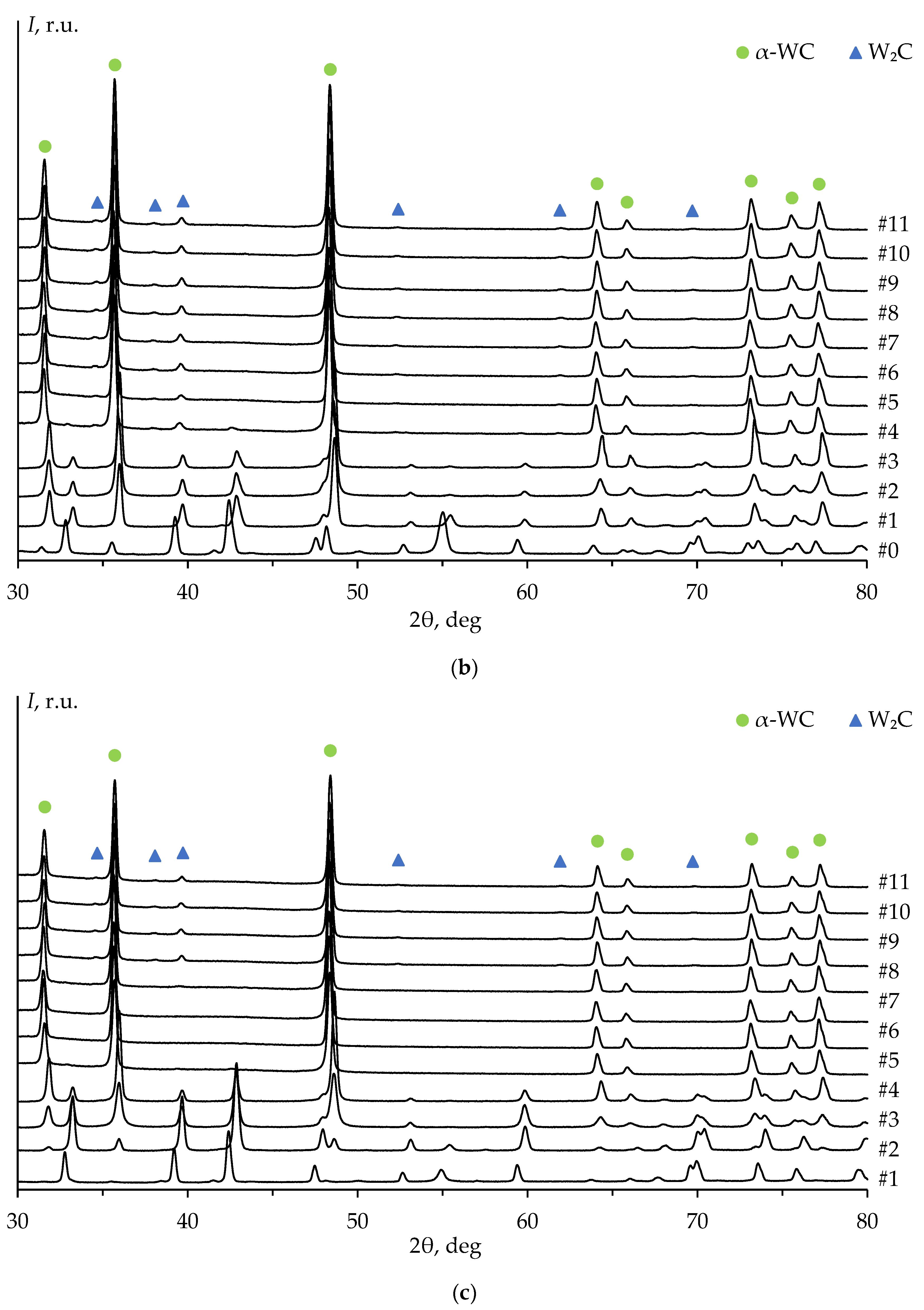
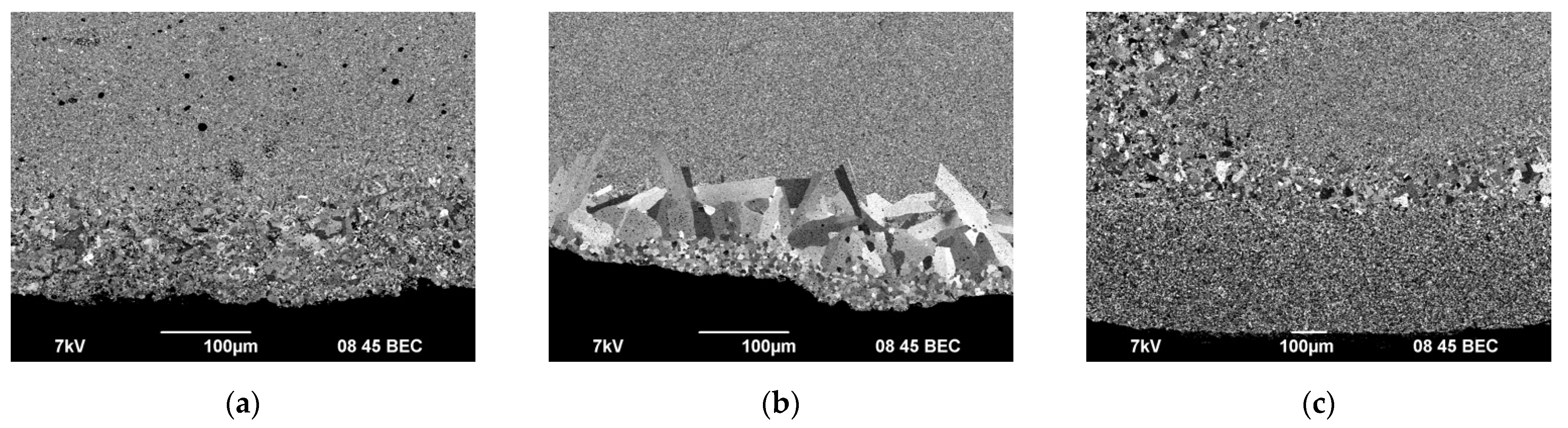
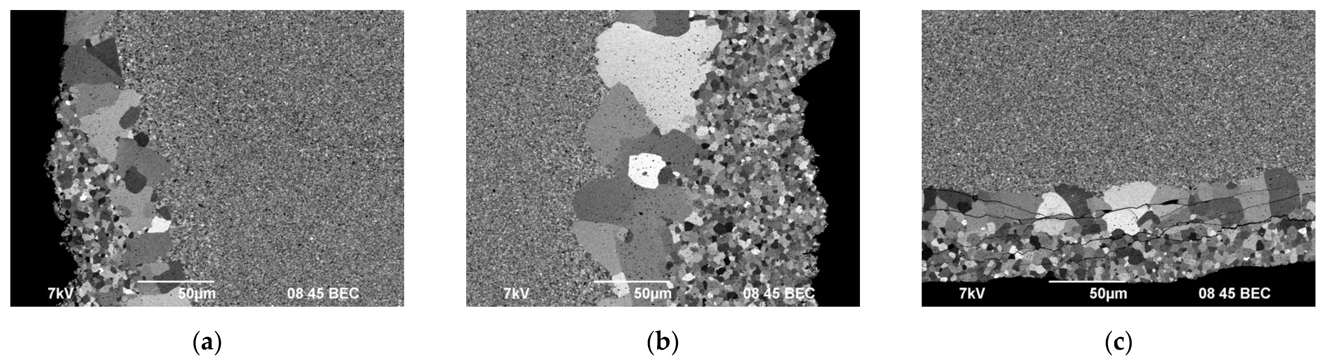
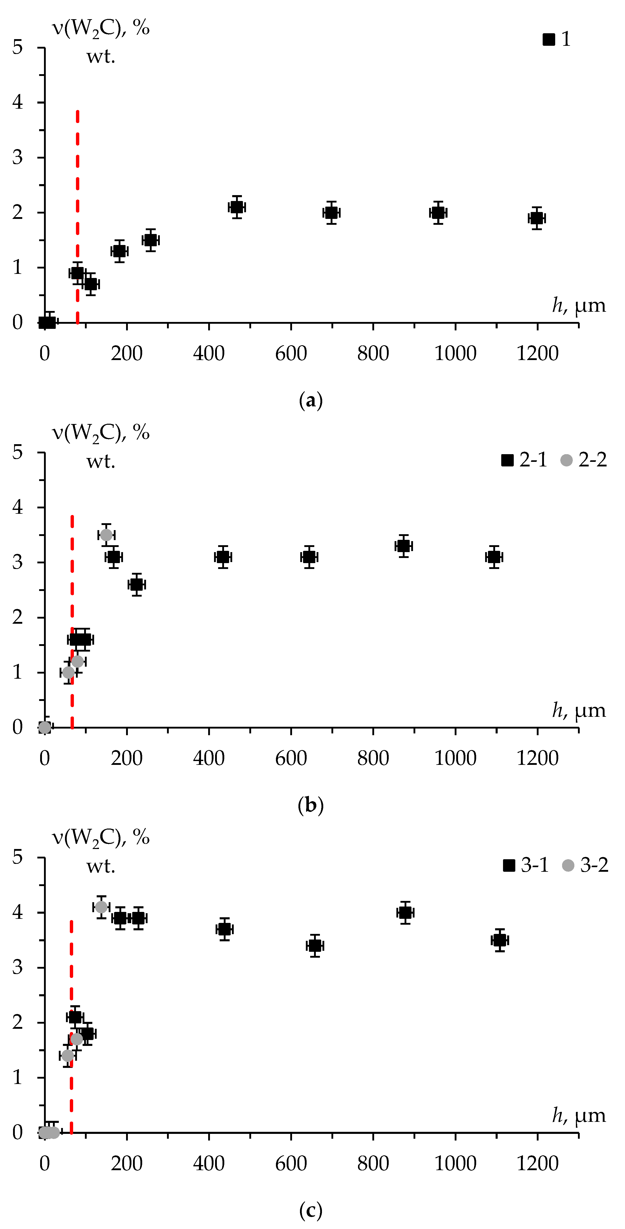
3.3. Layer-by-Layer Analysis of the WC Ceramics

Figure 7 shows images of ceramic #1 after different stages of the surface mechanical treatment. The characteristic appearance of the ceramics with untreated initial surface (stage #0) is presented in Figure 7a. Graphite foil residues were visible on the specimen surface. This layer was removed during the initial mechanical treatment of the specimens (stage #1, Figure 7b). The gray metallic color characteristic of binderless tungsten carbide appeared after the second stage of the mechanical treatment (stage #2, Figure 7c).
Figure 8 shows the XRD patterns of ceramics #1–3 after each stage of the mechanical treatment, including the diffraction pattern of the untreated surface (stage #0, Figure 7a). The XRD peaks on the untreated surface pattern correspond to the α-WC and graphite phases. The high-intensity XRD peak of graphite on the diffraction pattern at 2θ ≈ 54° was explained by the presence of graphite foil residues on the untreated surface of the specimens (Figure 7a). The graphite peak on the diffraction pattern was not observed after the second stage of the surface mechanical treatment of ceramic #1 (Figure 8a) and after the third stage of the treatment of ceramics #2 and #3 (Figure 8b,c).
The diffraction peaks corresponding to W2C phase were observed on the patterns starting from the fourth stage of the mechanical treatment. The intensity of W2C peaks increased with the total removed layer thickness (Figure 9a). These results were similar to those of ceramics 2 and 3 (Figure 9b,c).
Table 2 presents the results of the quantitative XRD of ceramics #1–3 after various stages of the surface mechanical treatment. It can be seen from the data in Table 2 that there was no difference (within the uncertainty) in the mass fraction of W2C phase for the ceramics #2 and #3 sintered under the same conditions.
Figure 10, Figure 11 and Figure 12 shows the results of the SEM studies of ceramics 1–3. Ceramics 2-2 and 3-2 were examined according to the scheme shown in Figure 2.
As can be seen in Figure 10, Figure 11 and Figure 12, the surface layers of the ceramics were characterized by nonuniform distribution of grain sizes, including the presence of abnormally large grains. Areas with non-uniform grain size distribution had a clear boundary. The thickness of the layers was 50–100 μm. The size of abnormally large grains reached 50 μm. Abnormally large grains can be observed at the very edge of the specimen cross section (Figure 11c), which came in contact with a graphite foil during sintering. Additionally, there was another thin layer with a clear boundary, containing grains whose size exceeded the average one in the main volume of the specimens by 2–3 times (most prominently in Figure 11a,b). Despite the difference in the sintering temperatures, there was no difference in the surface layer depth in ceramics #2 and #3. The grains in the surface layer of ceramic #1 (Figure 10) were mostly elongated. The average size of the abnormally large grains in ceramics 1 was much smaller than the one in ceramics 2 and 3.
A number of researchers reported about abnormal grain growth in tungsten carbide at Spark Plasma Sintering [5,30,31]. Abnormal grain growth is also often detected in the study of WC–Co hard alloys [15,17,32,33,34,35]. Researchers note that increased concentration of carbon in powder is one of the key factors contributing to the appearance of large grains in fine-grained materials based on WC [32,33,34,35].
Thus, the analysis of the presented experimental results showed that the binderless tungsten carbide specimens obtained by SPS method have nonuniform microstructure and phase composition. It was presumed that the heterogeneity was due to the carburization of the surface layers of tungsten carbide.

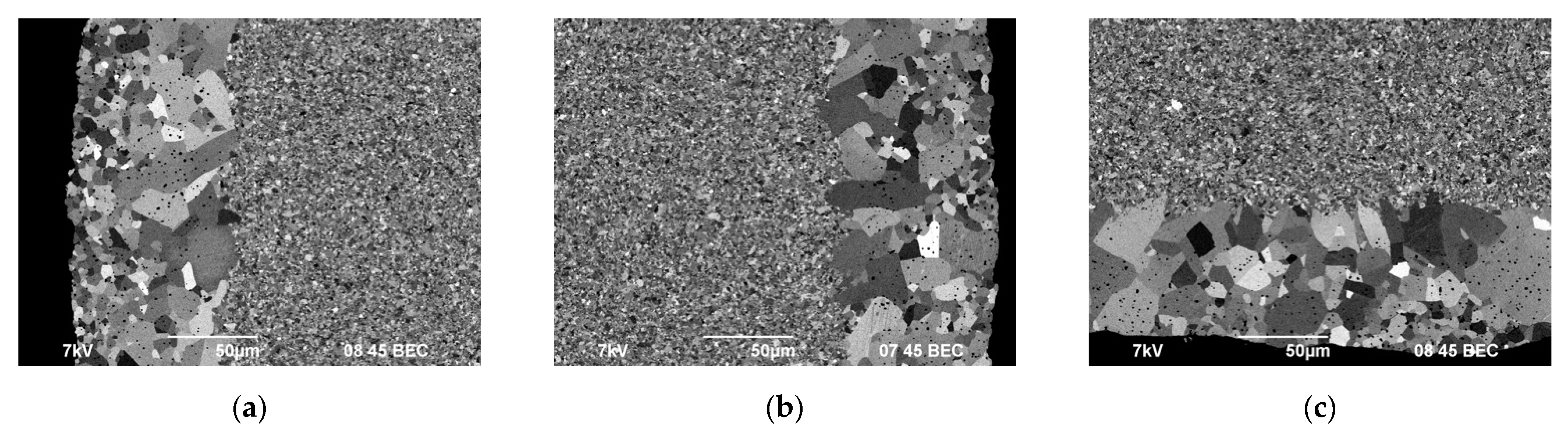
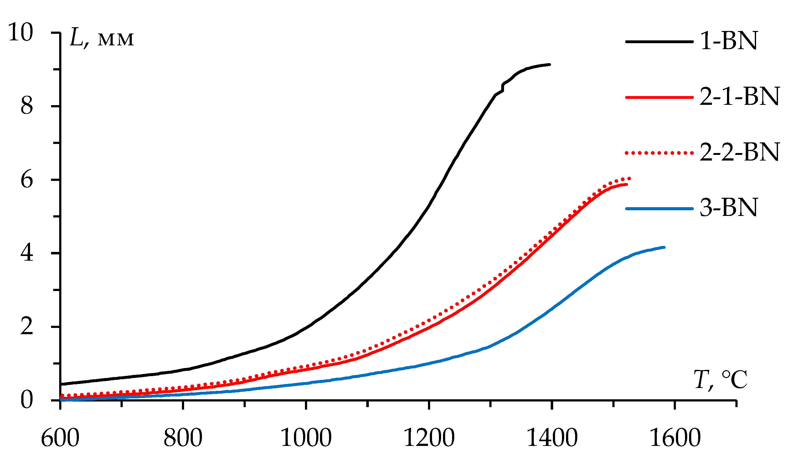
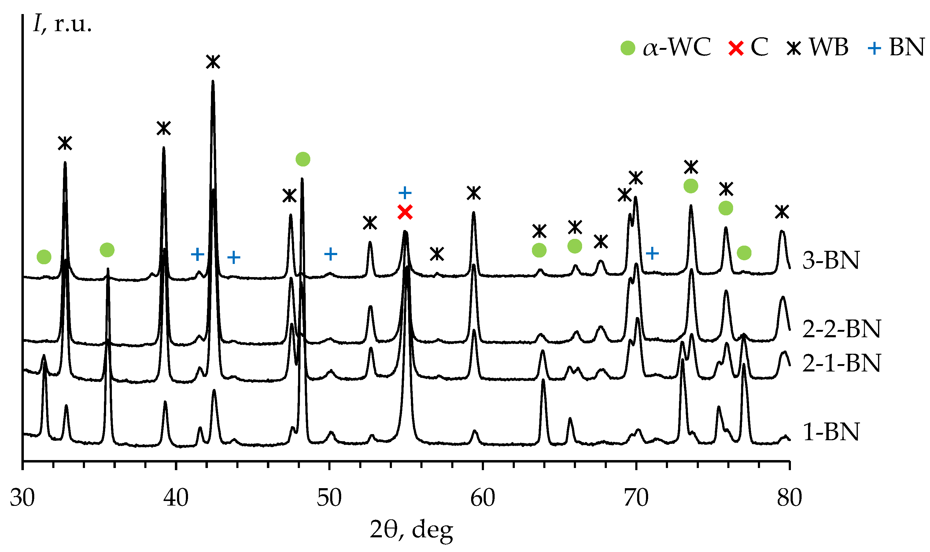
3.4. Influence of BN Coating on the Phase Composition and Microstructure of the WC Ceramics

To minimize the carburization effect of the surface layers, graphite molds with a protective coating of boron nitride on the inner surface were used. The protective coating was also applied to the graphite foil and to the punch surface. Figure 13 presents the temperature shrinkage curves L(T) of the WC powders sintered in the graphite molds with BN coating. A comparison of the curves L(T) shown in Figure 6 and Figure 13 revealed that there was no effect of BN coating on the character of the curves L(T).
Figure 14 presents the XRD patterns of the untreated surface (stage #0) of ceramics #1–3 sintered in the graphite molds with BN coating. The XRD peaks of α-WC phase, graphite, tungsten boride WB (ICDD PDF 00-035-0738), boron nitride BN (ICDD PDF 01-085-1068) were observed on the diffraction patterns of the specimens.
Traces of WB and BN phases were observed in all ceramics up to #3–4 stages of the surface mechanical treatment. At the same time, one of the most intense peaks of WB phase (at 2θ ≈ 39.2°) overlapped with the most intense peak of W2C phase. In this regard, there was no reliable evidence that W2C phase was present in the ceramics at stages #1–4 of the surface treatment. Full XRD patterns of the ceramics #1–3 sintered in the graphite molds with BN coating are presented in Figure 15.
Figure 16 shows the results of the SEM investigation of microstructure at the edge of the lower face of ceramics #1–3 sintered in the graphite molds with BN coating.
Figure 17 presents the results of the SEM investigation (according to the scheme in Figure 2) of ceramics #2 cross section.
Areas with non-uniform grain size distribution were observed on the ceramic surface sintered in the mold with BN coating (Figure 16 and Figure 17). The areas of non-uniform microstructure were found to have a clear boundary between the layers. The area thickness varied from 50 to 150 µm (Figure 17a,b). Cracks observed in the surface layer indicated a low fracture toughness of this layer (Figure 17c).

4. Discussion

To analyze the results presented, it was necessary to consider the nature of the phase transformations in tungsten carbide-based ceramics at sintering previously. It is a widely held view that W2C → α-WC phase change is possible only in the presence of excess carbon in accordance with the reaction [25,36]:
W2C + C → 2 α-WC.
As mentioned in the introduction to the paper, adsorbed oxygen is present on the surface of WC powder particles [26]. Oxygen reacts with carbon in WC carbide particles to form carbon dioxide (CO2) in the process of heating WC powder:
2 α-WC + O2 → W2C + CO2 (g).
This leads to a decrease in the carbon concentration in the carbide particles and the formation of W2C phase particles. This process is also known as decarbonization [27,37].
As was pointed out in the introduction, the existence of α-WC phase is a narrow carbon concentration range. The equilibrium carbon content in α-WC is 6.13% wt. Even a slight deviation of the carbon concentration from its equilibrium value leads to the formation of W2C particles [25,27,37].
Figure 18 shows the distribution of the mass fraction of W2C phase over the specimen depth in ceramics #1–3. It was taken into account that at the first stages of the treatment, the graphite foil residues were found on the specimen surface. In this regard, the depth reference point correction by the thickness of the layer containing graphite was made.
According to the results of the XRD studies, the layer with a thickness of at least 50 µm that did not contain W2C phase on the ceramic surface. According to the results of the SEM studies, abnormal grain growth processes were taking place in the surface layer. The phase composition of the specimens was a mixture of α-WC and W2C phases in deeper layers. There was no significant difference in the mass fraction of W2C phase at a depth of more than 200–300 µm.
As mentioned above, W2C → α-WC phase change was possible only in the presence of “free” carbon (Equation (1)). It seems possible that the detection depth of W2C phase corresponded to a rough estimation of the carbon diffusion depth into the ceramic surface. As can be seen from Figure 18, this value was at least 50 μm.
Due to the classical equation (solution of Fick’s law), the diffusion layer thickness increased with the square root of the sintering time:
x C = t D *
t—the sintering time, D*—the effective diffusion coefficient:
D * = D v + δ / d D b
Dv—the volume diffusion coefficient of carbon in WC, Db—the grain boundary diffusion coefficient of carbon in WC, δ—the grain boundary width (δ ≈ 5 × 10⁻¹⁰ m), d—the average grain size.
The diffusion coefficient temperature dependence may be written in the form:
D i = D 0 i e x p Q i / k T
D0i—the pre-exponential diffusion factor, Qi—the diffusion activation energy (in kTm, Tm = 3143 K—the melting point of α-WC phase), k—the Boltzmann constant.
It was demonstrated that the volume diffusion depth of carbon (14C) of fine-grained tungsten carbide did not exceed 0.5 µm at temperature of 2370 °C (the exposure time ~60 h) [38]. Table 1 presents the comparison of available literature data for the carbon diffusion activation energy and pre-exponential factor in tungsten carbide. The estimation of the carbon diffusion depth in WC according to the presented literature data was performed for powder 1: T1 = 1683 K, t1 = 28.2 min, d1 = 10−6 m.
The estimates of the carbon diffusion depth given in the paper (Figure 18) turned out to be significantly greater than the values calculated from the literature data (Table 3). Thus, it can be suggested that the effect of the abnormally deep carbon diffusion into tungsten carbide was observed in the spark plasma sintering process. The exact nature of this effect is not known.
It seems possible that there were three main factors contributing to a significant acceleration of the carbon diffusion process during sintering of tungsten carbide.
Firstly, it should be noted that SPS process of tungsten carbide is accompanied by plastic deformation of particles by the mechanism of power-law creep [48]. The strain can accelerate the carbon diffusion in the surface layers of ceramics based on tungsten carbide.
The second factor was the multistage process of W2C particle formation at sintering, which can lead to an increase in the error in determining the carbon diffusion depth. Two processes (decarbonization and carburization) occurred simultaneously during the sintering of WC-based ceramics. The decarbonization process led to an increase in the proportion of W2C, and the carburization process caused a decrease in the proportion of W2C. The rates of these processes may differ and have different activation energy values. As a result of the addition of the two processes, non-monotonic character of the estimated carbon diffusion depth from the temperature and time of SPS process can be obtained.
The third factor to be taken into account was nonuniform distribution of thermal and electric fields at SPS [11,49,50]. In particular, overheating of the specimen surface at increased heating rates may cause an increase in the carbon diffusion depth. However, it was difficult to expect a large difference in the temperatures of the central and surface layers during the sintering of tungsten carbide specimens. Therefore, it was assumed that the influence of this factor was insignificant.

5. Conclusions

The phase composition homogeneity of tungsten carbide specimens obtained by spark plasma sintering was investigated. This study showed that the phase composition and microstructure of the specimen surface layer significantly differed from the phase composition and microstructure of the central layer. The ceramic surface layers contained increased carbon concentration, which prevented the formation of W2C particles and caused intensive grain growth. There was no significant dependence of the carburized layer depth on the initial particle size and sintering temperature. According to the results of the X-ray diffraction studies, the carburized layer depth in the specimens was ~50 µm. The layer with a thickness of at least 50 µm with grains 10–50 times larger than the grain size in the main volume of the specimens was present near the surface. In the central layers of the ceramics, a uniform fine-grained microstructure and a homogeneous increased mass fraction of W2C compared to the raw powders were observed.
It seems possible that changes in the phase composition and abnormal grain growth in the surface layers of tungsten carbide ceramics were due to abnormally deep carbon diffusion during sintering. The excess carbon source can be the material of a graphite mold and graphite punches, as well as graphite foil, which was used to reduce the clearance between the specimen and the inner surface of the mold. The current study found that the boron nitride coating did not completely eliminate the carburization effect of the surface layers of tungsten carbide ceramics.

Author Contributions

Methodology, V.N.C. and A.V.N.; investigation, K.E.S., E.A.L., A.A.M., M.S.B., N.V.I. and Y.V.B.; data curation, K.E.S. and P.V.A.; writing—original draft preparation, K.E.S.; writing—review and editing, K.E.S., P.V.A. and A.V.N.; supervision, V.N.C.; project administration, P.V.A. All authors have read and agreed to the published version of the manuscript.

Funding

This research was funded by the Russian Science Foundation, grant number 22-73-10175.

Institutional Review Board Statement

Not applicable.

Informed Consent Statement

Not applicable.

Data Availability Statement

Data are contained within the article.

Conflicts of Interest

The authors declare no conflict of interest.

References

  1. Gille, G.; Szesny, B.; Dreyer, K.; van den Berg, H.; Schmidt, J.; Gestrich, T.; Leitner, G. Submicron and ultrafine grained hardmetals for microdrills and metal cutting inserts. Int. J. Refract. Met. Hard Mater. 2022, 20, 3–22. [Google Scholar] [CrossRef]
  2. Zak Fang, Z.; Wang, X.; Ryu, T.; Hwang, K.-S.; Sohn, H.Y. Synthesis, sintering, and mechanical properties of nanocrystalline cemented tungsten carbide—A review. Int. J. Refract. Met. Hard Mater. 2009, 27, 288–299. [Google Scholar] [CrossRef]
  3. Shichalin, O.O.; Buravlev, I.Y.; Portnyagin, A.S.; Dvornik, M.I.; Mikhailenko, E.A.; Golub, A.V.; Zakharenko, A.M.; Sukhorada, A.E.; Talskikh, K.Y.; Buravleva, A.A.; et al. SPS hard metal alloy WC-8Ni-8Fe fabrication based on mechanochemical synthetic tungsten carbide powder. J. Alloys Compd. 2020, 816, 152547. [Google Scholar] [CrossRef]
  4. Shichalin, O.O.; Buravlev, I.Y.; Papynov, E.K.; Golub, A.V.; Belov, A.A.; Buravleva, A.A.; Sakhnevich, V.N.; Dvornik, M.I.; Vlasova, N.M.; Gerasimenko, A.V.; et al. Comparative study of WC-based hard alloys fabrication via spark plasma sintering using Co, Fe, Ni, Cr, and Ti binders. Int. J. Refract. Met. Hard Mater. 2022, 102, 105725. [Google Scholar] [CrossRef]
  5. Sun, J.; Zhao, J.; Huang, Z.; Yan, K.; Shen, X.; Xing, J.; Gao, Y.; Jian, Y.; Yang, H.; Li, B. A Review on Binderless Tungsten Carbide: Development and Application. Nanomicro Lett. 2020, 12, 13. [Google Scholar] [CrossRef] [PubMed] [Green Version]
  6. Gubernat, A.; Rutkowski, P.; Grabowski, G.; Zientara, D. Hot pressing of tungsten carbide with and without sintering additives. Int. J. Refract. Met. Hard Mater. 2014, 43, 193–199. [Google Scholar] [CrossRef]
  7. Kim, H.-C.; Yoon, J.-K.; Doh, J.-M.; Ko, I.-Y.; Shon, I.-J. Rapid sintering process and mechanical properties of binderless ultra fine tungsten carbide. Mater. Sci. Eng. A 2006, 435–436, 717–724. [Google Scholar] [CrossRef]
  8. Kim, H.-C.; Shon, I.-J.; Garay, J.E.; Munir, Z.A. Consolidation and properties of binderless sub-micron tungsten carbide by field-activated sintering. Int. J. Refract. Met. Hard Mater. 2004, 22, 257–264. [Google Scholar] [CrossRef]
  9. Tokita, M. Progress of Spark Plasma Sintering (SPS) Method, Systems, Ceramics Applications an Industrialization. Ceramics 2021, 4, 160–198. [Google Scholar] [CrossRef]
  10. Buravlev, I.Y.; Shichalin, O.O.; Papynov, E.K.; Golub, A.V.; Gridasova, E.A.; Buravleva, A.A.; Yagofarov, V.Y.; Dvornik, M.I.; Fedorets, A.N.; Reva, V.P.; et al. WC-5TiC-10Co hard metal alloy fabrication via mechanochemical and SPS techniques. Int. J. Refract. Met. Hard Mater. 2021, 94, 105385. [Google Scholar] [CrossRef]
  11. Hu, Z.-Y.; Zhang, Z.-H.; Cheng, X.-W.; Wang, F.-C.; Zhang, Y.-F.; Li, S.-L. A review of multi-physical fields induced phenomena and effects in spark plasma sintering: Fundamentals and applications. Mater. Des. 2020, 191, 108662. [Google Scholar] [CrossRef]
  12. Olevsky, E.A.; Dudina, D.V. Field-Assisted Sintering: Science and Applications; Springer: Cham, Switzerland, 2018; p. 425. [Google Scholar] [CrossRef]
  13. Cavaliere, P. Spark Plasma Sintering of Materials; Springer: Cham, Switzerland, 2019; p. 781. [Google Scholar] [CrossRef]
  14. Isaeva, N.V.; Blagoveshchenskii, Y.V.; Blagoveshchenskaya, N.V.; Mel’nik, Y.I.; Samokhin, A.V.; Alekseev, N.V.; Astashov, A.G. Preparation of nanopowders of carbides and hard-alloy mixtures applying low-temperature plasma. Russ. J. Non-Ferr. Met. 2014, 55, 585–591. [Google Scholar] [CrossRef]
  15. Lantsev, E.A.; Malekhonova, N.V.; Nokhrin, A.V.; Chuvil’deev, V.N.; Boldin, M.S.; Andreev, P.V.; Smetanina, K.E.; Blagoveshchenskiy, Y.V.; Isaeva, N.V.; Murashov, A.A. Spark plasma sintering of fine-grained WC hard alloys with ultra-low cobalt content. J. Alloys Compd. 2021, 857, 157535. [Google Scholar] [CrossRef]
  16. Smetanina, K.E.; Andreev, P.V.; Lantsev, E.A.; Vostokov, M.M.; Malekhonova, N.V.; Murashov, A.A. Structural-phase features of WC-based ceramics obtained by the spark plasma sintering method. IOP Conf. Ser. Mater. Sci. Eng. 2021, 1014, 012053. [Google Scholar] [CrossRef]
  17. Lantcev, E.; Nokhrin, A.; Malekhonova, N.; Boldin, M.; Chuvil’deev, V.; Blagoveshchenskiy, Y.; Isaeva, N.; Andreev, P.; Smetanina, K.; Murashov, A. A Study of the Impact of Graphite on the Kinetics of SPS in Nano- and Submicron WC-10% Co Powder Compositions. Ceramics 2021, 4, 331–363. [Google Scholar] [CrossRef]
  18. Mouawad, B.; Soueidan, M.; Fabregue, D.; Buttay, C.; Bley, V.; Allard, B.; Morel, H. Full Densification of Molybdenum Powders Using Spark Plasma Sintering. Metall. Mater. Trans. A 2012, 43, 3402–3409. [Google Scholar] [CrossRef] [Green Version]
  19. Bokhonov, B.B.; Ukhina, A.V.; Dudina, D.V.; Anisimov, A.G.; Mali, V.I.; Batraev, I.S. Carbon uptake during Spark Plasma Sintering: Investigation through the analysis of the carbide «footprint» in a Ni–W alloy. RSC Adv. 2015, 5, 80228–80237. [Google Scholar] [CrossRef]
  20. Morita, K.; Kim, B.-N.; Yoshida, H.; Hiraga, K.; Sakka, Y. Distribution of carbon contamination in oxide ceramics occurring during spark-plasma-sintering (SPS) processing: II—Effect of SPS and loading temperatures. J. Eur. Ceram. Soc. 2018, 38, 2596–2604. [Google Scholar] [CrossRef]
  21. Morita, K.; Kim, B.-N.; Hiraga, K.; Yoshida, H. Fabrication of high-strength transparent MgAl2O4 spinel polycrystals by optimizing spark plasma sintering conditions. J. Mater. Res. 2009, 24, 2863–2872. [Google Scholar] [CrossRef]
  22. Wang, P.; Yang, M.; Zhang, S.; Tu, R.; Goto, T. Suppression of carbon contamination in SPSed CaF2 transparent ceramics by Mo foil. J. Eur. Ceram. Soc. 2017, 37, 4103–4107. [Google Scholar] [CrossRef]
  23. Yong, S.-M.; Choi, D.H.; Lee, K.; Ko, S.-Y.; Cheong, D.-I.; Park, Y.-J.; Go, S.-I. Study on carbon contamination and carboxylate group formation in Y2O3–MgO nanocomposites fabricated by spark plasma sintering. J. Eur. Ceram. Soc. 2020, 40, 847–851. [Google Scholar] [CrossRef]
  24. Li, H.; Khor, K.A.; Yu, L.G.; Cheang, P. Microstructure modifications and phase transformation in plasma-sprayed WC–Co coatings following post-spray spark plasma sintering. Surf. Coat. Technol. 2005, 194, 96–102. [Google Scholar] [CrossRef]
  25. Kurlov, A.S.; Gusev, A.I. Tungsten Carbides. Structure, Properties and Application in Hardmetals; Springer: Cham, Switzerland, 2013; p. 242. [Google Scholar] [CrossRef]
  26. Krasovskii, P.V.; Blagoveshchenskii, Y.V.; Grigorovich, K.V. Determination of oxygen in W-C-Co nanopowders. Inorg. Mater. 2008, 44, 954–959. [Google Scholar] [CrossRef]
  27. Kurlov, A.S.; Gusev, A.I. Vacuum annealing of nanocrystalline WC powders. Inorg. Mater. 2012, 48, 680–690. [Google Scholar] [CrossRef]
  28. Sestan, A.; Jenus, P.; Krmpotic, S.N.; Zavasnik, J.; Ceh, M. The role of tungsten phases formation during tungsten metal powder consolidation by FAST: Implications for high-temperature applications. Mater. Charact. 2018, 138, 308–314. [Google Scholar] [CrossRef]
  29. Sestan, A.; Zavasnik, J.; Krzmanc, M.M.; Kocen, M.; Jenus, P.; Novak, S.; Ceh, M.; Dehn, G. Tungsten carbide as a deoxidation agent for plasma-facing tungsten-based materials. J. Nucl. Mater. 2019, 524, 135–140. [Google Scholar] [CrossRef]
  30. Cha, S.I.; Hong, S.H. Microstructures of binderless tungsten carbides sintered by spark plasma sintering process. Mater. Sci. Eng. A 2003, 356, 381–389. [Google Scholar] [CrossRef]
  31. Poetschke, J.; Richter, V.; Gestrich, T.; Michaelis, A. Grain growth during sintering of tungsten carbide ceramics. Int. J. Refract. Met. Hard Mater. 2014, 43, 309–316. [Google Scholar] [CrossRef]
  32. Morton, C.W.; Wills, D.J.; Stjernberg, K. The temperature ranges for maximum effectiveness of grain growth inhibitors in WC–Co alloys. Int. J. Refract. Met. Hard Mater. 2005, 23, 287–293. [Google Scholar] [CrossRef]
  33. Li, T.; Li, Q.; Lu, L.; Fuh, J.Y.H.; Yu, P.C. Abnormal grain growth of WC with small amount of cobalt. Philos. Mag. 2007, 87, 5657–5671. [Google Scholar] [CrossRef]
  34. Yang, D.-Y.; Kang, S.-J.L. Suppression of abnormal grain growth in WC–Co via pre-sintering treatment. Int. J. Refract. Met. Hard Mater. 2009, 27, 90–94. [Google Scholar] [CrossRef]
  35. Yang, D.-Y.; Yoon, D.Y.; Kang, S.-J.L. Suppression of Abnormal Grain Growth in WC–Co via Two-Step Liquid Phase Sintering. J. Am. Ceram. Soc. 2011, 94, 1019–1024. [Google Scholar] [CrossRef]
  36. Reddy, K.M.; Rao, T.N.; Joardar, J. Stability of nanostructured W-C phases during carburization of WO3. Mater. Chem. Phys. 2011, 128, 121–126. [Google Scholar] [CrossRef]
  37. Yuan, J.; Zhan, Q.; Huang, J.; Ding, S.; Li, H. Decarburization mechanisms of WC–Co during thermal spraying: Insights from controlled carbon loss and microstructure characterization. Mater. Chem. Phys. 2013, 142, 165–171. [Google Scholar] [CrossRef]
  38. Buhsmer, C.; Crayton, P. Carbon self-diffusion in tungsten carbide. J. Mater. Sci. 1971, 6, 981–988. [Google Scholar] [CrossRef]
  39. McCarty, L.V.; Donelson, R.; Hehemann, R. A Diffusion Model for Tungsten Powder Carburization. Metall. Mater. Trans. A 1987, 18, 969–974. [Google Scholar] [CrossRef]
  40. Treheux, D.; Dubois, J.; Fantozzi, G. Bulk and grain boundary diffusion of 14C in tungsten hemicarbide. Ceram. Int. 1981, 7, 142–148. [Google Scholar] [CrossRef]
  41. Kharatyan, S.L.; Chatilyan, H.A.; Arakelyan, L.H. Kinetics of tungsten carbidization under non-isothermal conditions. Mater. Res. Bull. 2008, 43, 897–906. [Google Scholar] [CrossRef]
  42. Samsonov, G.V.; Vinitsky, I.M. Refractory Compounds; Metallurgizdat: Moscow, Russia, 1976; p. 560. (In Russian) [Google Scholar]
  43. Lassner, E.; Schubert, W. Tungsten: Properties, Chemistry, Technology of the Element, Alloys, and Chemical Compounds; Springer: New York, NY, USA, 1999; p. 422. [Google Scholar] [CrossRef]
  44. Fries, R.J.; Cummings, J.E.; Hoffman, C.G.; Daily, S.A. Carbide layer-growth rates on tungsten-molybdenum and tungsten-rhenium alloys. J. Nucl. Mater. 1971, 39, 35–48. [Google Scholar] [CrossRef]
  45. Andrews, M.R. Diffusion of Carbon through Tungsten and Tungsten Carbide. J. Phys. Chem. 1925, 29, 462–472. [Google Scholar] [CrossRef]
  46. Eremeev, V.S. Investigation of carbon diffusion from uranium monocarbide to molybdenum and tungsten. At. Energy 1968, 25, 489–493. (In Russian) [Google Scholar] [CrossRef]
  47. Samsonov, G.V.; Epic, A.P. Coatings Made of Refractory Compounds; Metallurgizdat: Moscow, Russia, 1964; p. 107. (In Russian) [Google Scholar]
  48. Lantsev, E.A.; Nokhrin, A.V.; Chuvil’deev, V.N.; Boldin, M.S.; Blagoveshchenskiy, Y.V.; Andreev, P.V.; Murashov, A.A.; Smetanina, K.E.; Isaeva, N.V.; Terentev, A.V. Study of high-temperature deformation features of ceramics of binderless tungsten carbide with various particle sizes. Inorg. Mater. Appl. Res. 2022, 13, 1324–1332. [Google Scholar] [CrossRef]
  49. Anselmi-Tamburini, U.; Gennari, S.; Garay, J.E.; Munir, Z.A. Fundamental investigations on the spark plasma sintering/synthesis process II. Modeling of current and temperature distributions. Mater. Sci. Eng. A 2005, 394, 139–148. [Google Scholar] [CrossRef]
  50. Molenat, G.; Durand, L.; Galy, J.; Couret, A. Temperature control in spark plasma sintering: An FEM approach. J. Metall. 2010, 2010, 145431. [Google Scholar] [CrossRef]
Figure 1. Basic spark plasma sintering system configuration. Scheme.
Coatings 13 01051 g001
Figure 2. Cutting scheme (a) and location of cross section areas under study (b) of the WC ceramics.
Coatings 13 01051 g002
Figure 3. SEM images of WC powder #1 (a), #2 (b), #3 (c).
Coatings 13 01051 g003
Figure 4. XRD patterns of WC powders #1–3. The pattern number corresponds to the powder number (Table 1).
Coatings 13 01051 g004
Figure 5. Sintering diagrams of ceramics #1 (a), #2 (b), #3 (c).
Coatings 13 01051 g005
Figure 6. Temperature shrinkage curves L(T) of WC powders 1–3.
Coatings 13 01051 g006
Figure 7. Appearance of ceramic #1 after various stages of the surface mechanical treatment: untreated initial surface—stage #0 (a), stage #1 (b), stage #2 (c). Graphite foil remains on the ceramic surface after sintering (a), which can only be removed by mechanical treatment.
Coatings 13 01051 g007
Figure 8. XRD patterns of ceramic 1 (a), 2 (b), 3 (c) after every stage of the surface treatment.
Coatings 13 01051 g008aCoatings 13 01051 g008b
Figure 9. Sections of the XRD patterns of ceramic #1 (a), #2 (b), #3 (c) after various stages of the surface treatment. The intensity of the W2C phase peaks increases with increasing thickness of the removed layer.
Coatings 13 01051 g009
Figure 10. Microstructure of ceramic #1. SEM.
Coatings 13 01051 g010
Figure 11. Microstructure of ceramic #2 cross section: area A (a), area B (b), area C (c). SEM. Abnormally large grains are observed at the edges of the sample. The edges came in contact with a graphite foil during sintering.
Coatings 13 01051 g011
Figure 12. Microstructure of ceramic #3 cross section: area A (a), area B (b), area C (c). SEM.
Coatings 13 01051 g012
Figure 13. Temperature shrinkage curves L(T) of WC powders #1–3 sintered in the graphite molds coated with BN.
Coatings 13 01051 g013
Figure 14. XRD patterns of the untreated initial surface (stage #0) of ceramics #1–3 sintered in the graphite molds coated with BN.
Coatings 13 01051 g014
Figure 15. XRD patterns of ceramic #1 (a), #2 (b), #3 (c) sintered in the graphite molds coated with BN.
Coatings 13 01051 g015aCoatings 13 01051 g015b
Figure 16. Microstructure of ceramic #1 (a), #2 (b), #3 (c). SEM.
Coatings 13 01051 g016
Figure 17. Microstructure of ceramic #2 cross section: area A (a), area B (b), area C (c). SEM.
Coatings 13 01051 g017
Figure 18. Dependence of W2C mass fraction on the distance from the ceramic surface #1 (a), #2 (b), #3 (c). The red vertical line indicates the distance from the surface where the W2C phase peaks were indicated on the XRD patterns.
Coatings 13 01051 g018
Table 1. The characteristics of the WC powders.
Powder123
Specific surface area, m2/g4.040.480.13
Average particle size, nm958003000
Oxygen content, % wt.0.40 ± 0.010.25 ± 0.010.12 ± 0.01
Carbon content, % wt.6.32 ± 0.016.14 ± 0.016.13 ± 0.01
Content of α-WC, % wt.97.4 ± 0.298.6 ± 0.298.4 ± 0.2
Content of W2C, % wt.-1.4 ± 0.21.6 ± 0.2
Content of W, % wt.2.6 ± 0.2--
Table 2. Results of the quantitative XRD analysis of WC ceramics 1–3 depending on the stage of the surface treatment.
StageContent of W2C, % wt.
Ceramic #1Ceramics #2Ceramics #3
Sample #1Sample #2-1Sample #2-2Sample #3-1Sample #3-2
#0–3-----
#40.9 ± 0.21.6 ± 0.21.0 ± 0.22.1 ± 0.21.4 ± 0.2
#50.7 ± 0.21.6 ± 0.21.2 ± 0.21.8 ± 0.21.7 ± 0.2
#61.3 ± 0.23.1 ± 0.23.5 ± 0.23.9 ± 0.24.1 ± 0.2
#71.5 ± 0.22.6 ± 0.2(*)3.9 ± 0.2(*)
#82.1 ± 0.23.1 ± 0.2 3.7 ± 0.2
#92.0 ± 0.23.1 ± 0.2 3.4 ± 0.2
#102.0 ± 0.23.3 ± 0.2 4.0 ± 0.2
#111.9 ± 0.23.1 ± 0.2 3.5 ± 0.2
(*) The surface treatment of the specimen has been completed. The specimen was cut in accordance with the scheme shown in Figure 2b to the SEM study.
Table 3. Carbon diffusion parameters in tungsten carbide.
PhaseMechanismD0, m2/sQ, kTmReferencesxC, μm
α-WCVolume1.9 × 10−1014.1[38]5
Grain boundary4.6 × 10−211.4
(*)10−89.3[39]1
W2CVolume1.8 × 10−314.6[40]2
Grain boundary1.8 × 10−811.0
(*)6.7 × 10−411.9[41]16
2 × 10−413.6[42]2
0.116.0[43,44,45]4
3020.0[46,47]2
(*) There is no clarification about the carbon diffusion mechanism in a number of studies [39,41,42,43,44,45,46,47]. In this regard, it is assumed that the effective diffusion coefficient is specified.
Disclaimer/Publisher’s Note: The statements, opinions and data contained in all publications are solely those of the individual author(s) and contributor(s) and not of MDPI and/or the editor(s). MDPI and/or the editor(s) disclaim responsibility for any injury to people or property resulting from any ideas, methods, instructions or products referred to in the content.

