
Electromagnetic Shielding of Composite Films Based on Graphite, Graphitized Carbon Black and Iron-Oxide

 ,
,  and
and
Abstract
:1. Introduction
2. Materials and Methods
- (a).
- The filler and the polymer were carefully weighed with a Kern ABJ 220-4NM scale.
- (b).
- The components were mixed in certain ratios (by weight) and thoroughly stirred until they became homogeneous so that they formed a composite.
- (c).
- The prepared suspension was employed to obtain coatings onto a horizontal surface, as a thin layer of a certain thickness. Cardboard sheets (40 cm × 40 cm) were used as a substrate.
- (d).
- The composition was finally dried at room temperature.
3. Results
3.1. Electrical Properties of Composites
3.2. Shielding Properties of Composites
4. Conclusions
Author Contributions
Funding
Institutional Review Board Statement
Informed Consent Statement
Data Availability Statement
Acknowledgments
Conflicts of Interest
References
- Pawar, S.P.; Biswas, S.; Kar, G.P.; Bose, S. High Frequency Millimetre Wave Absorbers Derived from Polymeric Nanocomposites. Polymer 2016, 84, 398–419. [Google Scholar] [CrossRef]
- Cekan, P.; Hovanec, M.; Sabo, J. Human factor in conversation between subordinates and managers. Nase More 2016, 63, 241–243. [Google Scholar] [CrossRef]
- Barnes, F.S.; Greenebaum, B. (Eds.) Biological and Medical Aspects of Electromagnetic Fields, 3rd ed.; CRC Press: Boca Raton, FL, USA, 2018. [Google Scholar]
- Krewski, D.; Byus, C.V.; Glickman, B.W.; Lotz, W.G.; Mandeville, R.; Salem, T.; Weaver, D.F. Recent advances in research on radiofrequency fields and health: 2001–2003. J. Toxicol. Environ. Health 2001, 4, 145–159. [Google Scholar] [CrossRef] [PubMed]
- Stilgoe, J. The (co-)production of public uncertainty: UK scientific advice on mobile phone health risks. Public Underst. Sci. 2007, 16, 45–61. [Google Scholar] [CrossRef]
- Hardell, L.; Mild, K.H.; Carlberg, M. Further aspects on cellular and cordless telephones and brain tumours. Int. J. Oncol. 2003, 22, 399–407. [Google Scholar] [CrossRef]
- Aerts, S.; Plets, D.; Verloock, L.; Martens, L.; Joseph, W. Assessment and comparison of total RF-EMF exposure in femtocell and macrocell base station scenarios. Radiat. Prot. Dosim. 2014, 162, 236–243. [Google Scholar] [CrossRef]
- Ott, H.W. Electromagnetic Compatibility Engineering; Wiley: New York, NY, USA, 2009. [Google Scholar]
- Wake, K.; Laakso, I.; Hirata, A.; Chakarothai, J.; Onishi, T.; Watanabe, S.; de Santis, V.; Feliziani, M.; Taki, M. Derivation of Coupling Factors for Different Wireless Power Transfer Systems: Inter- and Intralaboratory Comparison. IEEE Trans. Electromagn. Compat. 2016, 59, 677–685. [Google Scholar] [CrossRef]
- De Paulis, F.; Nisanci, M.H.; Orlandi, A.; Koledintseva, M.Y.; Drewniak, J.L. Design of Homogeneous and Composite Materials from Shielding Effectiveness Specifications. IEEE Trans. Electromagn. Compat. 2014, 56, 343–351. [Google Scholar] [CrossRef]
- Mirotznik, M.S.; Yarlagadda, S.; McCauley, R.; Pa, P. Broadband electromagnetic modeling of woven fabric composites. IEEE Trans. Microw. Theory Technol. 2012, 60, 158–169. [Google Scholar] [CrossRef]
- De Rosa, I.M.; Mancinelli, R.; Sarasini, F.; Sarto, M.S.; Tamburrano, A. Electromagnetic Design and Realization of Innovative Fiber-Reinforced Broad-Band Absorbing Screens. IEEE Trans. Electromagn. Compat. 2009, 51, 700–707. [Google Scholar] [CrossRef]
- Wang, X. Investigation of Electromagnetic Shielding Effectiveness of Nanostructural Carbon Black/ABS Composites. J. Electromagn. Anal. Appl. 2011, 3, 160–164. [Google Scholar] [CrossRef]
- Mikinka, E.; Siwak, M. Recent advances in electromagnetic interference shielding properties of carbon-fibre-reinforced polymer composites—A topical review. J. Mater. Sci. Mater. Electron. 2021, 32, 24585–24643. [Google Scholar] [CrossRef]
- Butenko, O.; Boychuk, V.; Savchenko, B.; Kotsyubynsky, V.; Khomenko, V.; Barsukov, V. Pure ultrafine magnetite from carbon steel wastes. Mater. Today Proc. 2019, 6, 270–278. [Google Scholar] [CrossRef]
- Ramadan, A.A.; Gould, R.D.; Ashhour, A. On the Van der Pauw method of resistivity measurements. Thin Solid Films 1994, 239, 272–275. [Google Scholar] [CrossRef]
- Kruželák, J.; Kvasničáková, A.; Hložeková, K.; Hudec, I. Progress in polymers and polymer composites used as efficient materials for EMI shielding. Nanoscale Adv. 2021, 3, 123–172. [Google Scholar] [CrossRef]
- Rahaman, M.; Chaki, T.K.; Khastgir, D.J. Development of high performance EMI shielding material from EVA, NBR, and their blends: Effect of carbon black structure. J. Mater. Sci. 2011, 46, 3989–3999. [Google Scholar] [CrossRef]
- Brigandi, P.J.; Cogen, J.M.; Pearson, R.A. Electrically conductive multiphase polymer blend carbon-based composites. Polym. Eng. Sci. 2014, 54, 1–16. [Google Scholar] [CrossRef]
- Tiwari, J.N.; Tiwari, R.N.; Kim, K.S. Zero-dimensional, one-dimensional, two-dimensional and three-dimensional nanostructured materials for advanced electrochemical energy devices. Prog. Mater. Sci. 2012, 57, 724–803. [Google Scholar] [CrossRef]
- Morari, C.; Balan, I. Methods for determining shielding effectiveness of materials. EEA 2015, 63, 126–136. [Google Scholar]
- Galehdar, A.; Rowe, W.; Ghorbani, K.; Callus, P.J.; John, S.; Wang, C.H. The effect of ply orientation on the performance of antennas in or on carbon fibre composites. Prog. Electromagn. Res. 2011, 116, 123–136. [Google Scholar] [CrossRef] [Green Version]
- Parmar, S.; Ray, B.; Date, K.; Datar, S. Modified graphene as a conducting ink for electromagnetic interference shielding. J. Phys. D Appl. Phys. 2019, 52, 375302. Available online: https://iopscience.iop.org/article/10.1088/1361-6463/ab2abb/pdf (accessed on 1 April 2022). [CrossRef]
- Li, L.; Yanjun, C.; Zhixia, Z.; Peng, T.; Haipeng, G.; Ping, L. Preparation of graphene/Fe3O4 composite varnish with excellent corrosion-resistant and electromagnetic shielding properties. Ceram. Int. 2020, 46, 22876–22882. [Google Scholar] [CrossRef]


| Conductive Additive | Mass Concentration | Specific Resistance (Ohm·cm) |
|---|---|---|
| Pure Black | 5% | 157.5 |
| Pure Black | 10% | 68.3 |
| Pure Black | 15% | 5.5 |
| Pure Black | 20% | 0.9 |
| CGP S-1 | 5% | 653.2 |
| CGP S-1 | 10% | 0.2 |
| CGP S-1 | 15% | 0.1 |
| CGP S-1 | 20% | 0.04 |
| CGP S-1/Pure Black | 3.33%/1.67% | 1314.1 |
| CGP S-1/Pure Black | 6.67%/3.33% | 36.6 |
| CGP S-1/Pure Black | 8%/4% | 3.9 |
| CGP S-1/Pure Black | 10%/5% | 2.0 |
| CGP S-1/Pure Black | 13.33%/6.67% | 0.3 |
| Sample ID | Concentrations of the Components (%) | Thickness (µm) | Specific Resistance (Ohm·cm) | ||
|---|---|---|---|---|---|
| CGP S-1 | Pure Black | Fe2O3 | |||
| 1 | 80 | - | - | 60 | 92 |
| 2 | - | 80 | - | 60 | 40 |
| 3 | 60 | 20 | - | 60 | 2.4 |
| 4 | 60 | 20 | - | 125 | 1.6 |
| 5 | 50 | 17 | 17 | 60 | 0.8 |
| 6 | 50 | 17 | 17 | 125 | 0.3 |
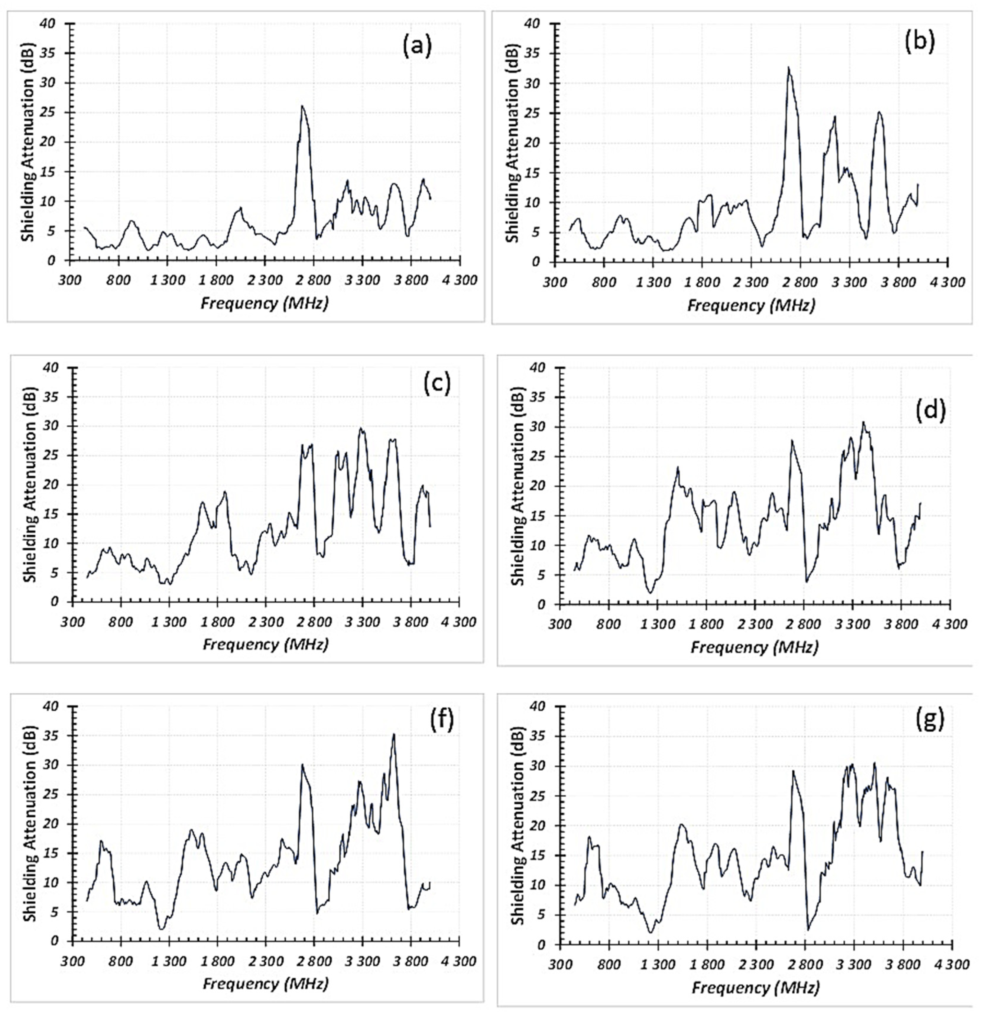
| Sample ID | Average Shielding Attenuation (SA), dB | SA maximum/ Corresponding Frequency (dB/GHz) | |||
|---|---|---|---|---|---|
| Frequency Range: 0.3–1.0 GHz | Frequency Range: 1.0–2.0 GHz | Frequency Range: 2.0–3.0 GHz | Frequency Range: 3.0–4.0 GHz | ||
| 1 | 4.1 | 3.7 | 7.8 | 9.8 | 26/2.70 |
| 2 | 4.9 | 6.0 | 10.1 | 14.1 | 32/2.69 |
| 3 | 6.6 | 9.7 | 13.2 | 18.6 | 30/3.30 |
| 4 | 8.4 | 13.2 | 14.3 | 18.5 | 32/3.40 |
| 5 | 9.1 | 11.6 | 13.7 | 17.8 | 35/3.7 |
| 6 | 9.8 | 11.6 | 13.5 | 21.3 | 31/3.3 (3.6) |
Publisher’s Note: MDPI stays neutral with regard to jurisdictional claims in published maps and institutional affiliations. |
© 2022 by the authors. Licensee MDPI, Basel, Switzerland. This article is an open access article distributed under the terms and conditions of the Creative Commons Attribution (CC BY) license (https://creativecommons.org/licenses/by/4.0/).
Share and Cite
Khomenko, V.; Butenko, O.; Chernysh, O.; Barsukov, V.; Suchea, M.P.; Koudoumas, E. Electromagnetic Shielding of Composite Films Based on Graphite, Graphitized Carbon Black and Iron-Oxide. Coatings 2022, 12, 665. https://doi.org/10.3390/coatings12050665
Khomenko V, Butenko O, Chernysh O, Barsukov V, Suchea MP, Koudoumas E. Electromagnetic Shielding of Composite Films Based on Graphite, Graphitized Carbon Black and Iron-Oxide. Coatings. 2022; 12(5):665. https://doi.org/10.3390/coatings12050665
Chicago/Turabian StyleKhomenko, Volodymyr, Oksana Butenko, Oksana Chernysh, Viacheslav Barsukov, Mirela Petruta Suchea, and Emmanouel Koudoumas. 2022. "Electromagnetic Shielding of Composite Films Based on Graphite, Graphitized Carbon Black and Iron-Oxide" Coatings 12, no. 5: 665. https://doi.org/10.3390/coatings12050665