Advantages of Yolk Shell Catalysts for the DRM: A Comparison of Ni/ZnO@SiO2 vs. Ni/CeO2 and Ni/Al2O3
by
 , ,
, ,
Cameron Alexander Hurd Price
1 ,
,
Emily Earles
1,
Laura Pastor-Pérez
1,2,
Jian Liu
1,* and
Tomas Ramirez Reina
1,* 1
Department of Chemical and Process Engineering, University of Surrey, Guildford GU2 7XH, UK
2
Laboratorio de Materiales Avanzados, Departamento de Química Inorgánica, Instituto Universitario de Materiales de Alicante, Universidad de Alicante, Apartado 99, E-03080 Alicante, Spain
*
Authors to whom correspondence should be addressed.
Chemistry 2019, 1(1), 3-16; https://doi.org/10.3390/chemistry1010003
Submission received: 9 November 2018
/
Revised: 5 December 2018
/
Accepted: 20 December 2018
/
Published: 28 December 2018
(This article belongs to the Special Issue CO2, a Carbon Source for Chemicals and Fuels)
Abstract
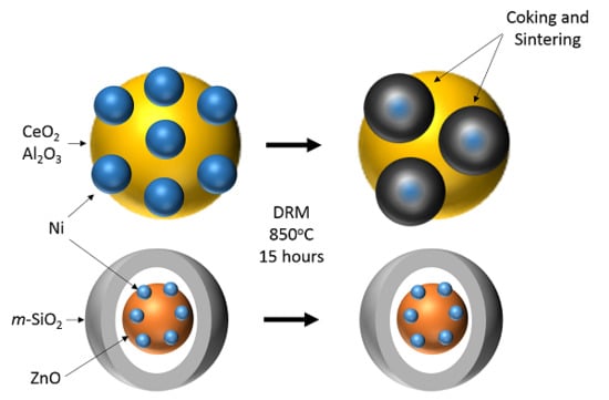
:Encapsulation of metal nanoparticles is a leading technique used to inhibit the main deactivation mechanisms in dry reforming of methane reaction (DRM): Carbon formation and Sintering. Ni catalysts (15%) supported on alumina (Al2O3) and ceria (CeO2) have shown they are no exception to this analysis. The alumina supported catalysts experienced graphitic carbonaceous deposits, whilst the ceria showed considerable sintering over 15 h of DRM reaction. The effect of encapsulation compared to that of the performance of uncoated catalysts for DRM reaction has been examined at different temperatures, before conducting longer stability tests. The encapsulation of Ni/ZnO cores in silica (SiO2) leads to advantageous conversion of both CO2 and CH4 at high temperatures compared to its uncoated alternatives. This work showcases the significance of the encapsulation process and its overall effects on the catalytic performance in chemical CO2 recycling via DRM.
1. Introduction
Reversing the present trend of growing greenhouse gas levels in the atmosphere and climate change is one of the significant scientific problems of the time. CH4 and CO2 are both recognized as major contributors to global climate change, therefore solutions that contribute to the reduction of both are essential in tackling this problem. Currently, carbon capture and storage (CCS) is the most established technology used in mitigating the CO2 concentrations in the atmosphere [1]. Although these processes are costly and provide no beneficial product.
Producing value added chemicals from CO2 and CH4 is an alternative economically viable process, which consumes and upgrades the gases via catalytic reactions [2]. Syngas is a desirable product which has the potential to be used in several industries as a chemical feedstock for commodity chemicals such as methanol and as a feedstock for Fischer Tropsch process [3,4].
Conversion to these higher value chemical products is achieved via the reforming of methane. For producing syngas, the primary used technique is steam reforming (SRM), which yields a product with a high stoichiometric H2/CO ratio of 3 [5].
This ratio constitutes a syngas product that is not always suitable for chemical synthesis, such as methanol production [6].
SRM:
ΔH298K = +206 kJ/mol ΔG298k = +142 kJ/mol
Due to the exothermic attributes of the steam reforming reaction, temperatures between 700–900 °C are mandatory in order to attain high conversions of both methane and H2O. However, along with the significant amount of steam required to maximize H2 [7], the main disadvantage is that unlike other reforming process, it only utilizes CH4 and not CO2.
Nevertheless, other reforming methods use CO2 in conjunction with CH4 to produce syngas:
BRM:
ΔH298K = +220 kJ/mol ΔG298k = +151 kJ/mol
ORM:
ΔH298K = +58 kJ/mol ΔG298k = −1 kJ/mol
Bi-reforming (BRM) yields syngas with a H2/CO value of 2, lower than that of SRM, producing a more advantageous composition for the Fischer Tropsch route. This value can also be tuned by adapting the initial steam to CO2 ratio [8].
Nonetheless, the BRM procedure still needs significant amounts of steam to provide the desirable ratio. The autothermic nature of this reaction highlights Oxy-CO2 Reforming (ORM) as the most desirable form of reforming in relation to kinetics [9]. This means that ORM benefits from superior energy efficiencies when likened to other reactions. However, significant safety concerns are associated with the reaction due to the presence of oxygen [5]; hence, this reforming technique will not be considered further in this work.
Alternatively, dry reforming of methane (DRM) that also uses CO2 with CH4 to generate syngas. It is a highly endothermic reaction favored at high temperature and low pressures [10], similar to that of SRM (Equation (1)). When compared to other reforming reactions it requires significant energy contribution, but has reduced operational costs [5].
DRM:
ΔH298K = +247 kJ/mol ΔG298k = +170 kJ/mol
Fischer Tropsch requires a ratio of around 2, yet DRM achieves a H2/CO ratio of approximately 1. Despite this, syngas with a reduced H2/CO ratio boosts the overall selectivity of long chain hydrocarbons [11]. In addition, the effluent of a DRM unit could be used to power a Solid Oxide Fuel Cell (SOFC) to obtain electricity from reformed greenhouse gases.
Thermodynamics of DRM are essential in determining the most suitable conditions to produce a desirable product yield. Conditions used typically allow side reactions to occur simultaneously with the fundamental reforming reaction: The reverse water gas shift (RWGS), Boudouard reaction and the C oxidation/reduction reactions (Equations (5)–(10)) can influence the overall performance of the catalyst and final product composition.
RWGS is the driving force of producing a H2/CO ratio of less than 1, as the simultaneous production of CO from this reaction causes an increase in relation to the consumption of H2 [12]. The presence of water vapor within the reaction environment as a result of the RWGS reaction then leads to the BRM reaction (Equation (2)) taking place in a cascade, which shifts the H2/CO product ratio to above 1, thus requiring carefully selective catalyst development to maintain the desired product ratio [13]. Carbon deposition (Equations (6)–(8)) is the foremost method of catalyst deactivation, with carbon accumulating across the exterior of the catalytic surface. This could be through many methods; obstruction of the metal active sites, the collapse of the catalyst support and the encapsulation of metal nanoparticles [14]. These reactions typically occur up to 700 °C, which is why typical reforming reactions are completed at higher temperature [10,15], although in DRM the decomposition of methane (Equation (7)) is the largest cause of coke deposition at temperatures above 700 °C [16]. Plausible catalysts should be impervious to carbon accumulation as a form of deactivation. This could be achieved by advancing catalysts that minimize the progression of CH4 decomposition or CO reduction, whilst enhancing the oxidation reactions (Equations (6)–(10)) [17].
The other major challenge in reforming is to avoid sintering of the supported metal nanoparticles as a second cause of catalyst deactivation; this agglomeration of particles forms larger metal surfaces, decreasing both the surface area and active sites [18]. Hence, inhibiting the deactivation methods and enhancing the lifetime of the catalysts are key features required in DRM catalysis.
Amongst the extensive assortment of catalysts reviewed in literature, active transition metals such as nickel and cobalt are frequently used due to their relatively high performance and small expense. The use of nickel presents a challenge, as it has a tendency for deactivation from coke formation at low temperatures, and sintering at high temperatures [19,20]. Despite this, however, the use of Ni catalytic formulations remains popular. Recently, the development of yolk shell/core shell materials is becoming prevalent owing to the benefits of a hierarchal morphology and numerous preparation methods [21,22]. The applications of these structures towards CO2 reforming is also emerging within the catalysis literature, with more recent works detailing Ni yolk shell [23] and core shell [24] catalysts for the DRM reaction, with some promising results. One such study concerning the use of a Ni/SiO2@CeO2 core shell material for dry reforming of biogas at 600 °C, found a 10% activity loss after 72 h on stream and a product ratio of approximately 0.5 maintained throughout [25]. Another study investigated an analogous material, 11 wt.% Ni/Ce@SiO2 in the yolk shell morphology, with a consistent ~100% conversion of CO2 at 750 °C for 40 h, although only at very low space velocities (WHSV = 6000 mL g−1h−1) [26].
Additionally, noble metals such as platinum and rhodium are known to have significant resistance to coking compared to nickel catalysts [27,28]. Their scarcity and cost makes them uneconomical for large scale applications [11].
The supporting material also helps determine the catalytic performance; Alumina is an effective support, with a large surface and positive impact on catalyst stability [29]. However, the acidity of the support promotes deactivation through coking and sintering [30]. Ceria (CeO2) is a popular support which is often employed alone or mixed. The redox nature of ceria supports promote the oxidation of carbon surface residue but also enhance the activation of CO2 on the support [31]. Recently, the stabilization of Ni in inorganic structures such as pyrochlore-perovskites has attracted attention, displaying promising improvements to catalytic lifespan in the DRM reaction [32].
Deactivation has also been inhibited through other methods; encapsulation of metal cores is one process which is deemed to enhance re-usability, activity and stability [21,33]. The shell prevents carbon accretion on the active metal nanoparticles by blocking a carbon build-up on the catalytic surface through the spatial confinement effect [34]. Sintering is also restricted, with the shell barrier removing the opportunity of agglomeration by separating individual active cores from one another. Shells are desirably porous and permeable, with core-shell catalysts in literature using SiO2 [26,35], TiO2 [36] and Al2O3 [37]. Issues have arisen due to nonhomogeneous dispersion of the metal nanoparticles. Yolk-shell catalysts are an exceptional improvement of the metal core-shell structure, with a characteristic void between the core and the shell which allows a configuration, offering a homogeneous reaction environment, while also creating a high surface area to volume ratio [21].
Under these premises, the intention of this work was to compare traditional materials such as Ni/Al2O3 and more advanced variations such as Ni/CeO2 to an encapsulated Ni–ZnO material for the use in DRM. This potential improvement aims to limit/inhibit deactivation mechanisms which are currently faced by Ni/Al2O3. An analysis of reaction conditions of dry reforming and the catalyst performances allows for beneficial discussion regarding key catalyst structure and composition to be used in further comprehensive research within DRM.
2. Experimental
2.1. Catalyst Preparation
Cerium support was synthesized through hydrolysis and precipitation, where Ce(NO3)3·6H2O (Sigma-Aldrich, St. Louis, MO, USA) was mixed with a solution of CH4N2O (Sigma-Aldrich) and H2O. The solution was mixed at 80 °C at atmospheric pressure for 24 h, with the resulting mixture being filtered under vacuum. The recovered solid was dried for 24 h at 80 °C and calcined at 400 °C for 4 h with a ramp of 5 °C min−1. The Alumina support used was γ-Alumina powder (Sasol, Johannesburg, South Africa).
The catalysts in this research were developed via wet impregnation, where the support material chosen was impregnated with calculated amounts of Ni(NO3)2·6H2O (Sigma-Aldrich). This was completed by dilution with acetone which was evaporated at reduced pressure in a rotary evaporator. Recovered solid was dried overnight at 80 °C and calcined at 400 °C for 4 h with a ramp of 5 °C min−1. The Ni content in all comparison catalysts was calculated to be 15%.
To begin the preparation of our yolk shell catalyst, ZIF-8 was synthesised from Zn(NO3)2·6H2O (Sigma-Aldrich) and 2-methylimidazole (Fischer Scientific, Hampton, NH, USA). This ZIF-8, once purified and dried, was added to an aqueous solution of 0.1 M Ni(CH3COO)2·4H2O (Sigma-Aldrich) and stirred for 12 h. The resulting blue solid was then centrifuged and dried.
The encapsulation of the Ni/ZIF-8 was achieved via forming a solution which could be compared to micro-emulsion techniques. The solution was first created by dissolving CTAB (Sigma-Aldrich) in water and ethanol, with a further addition of 25% ammonia solution and Ni/ZIF-8. TEOS (Sigma-Aldrich) was added to the solution and stirred for 24 h. The coated solid was heated for 24 h at 100 °C within a Teflon lined autoclave. The solids were separated from solution via centrifugation, dried at 100 °C overnight and calcined at 500 °C with a ramp of 2 °C min−1.
For clarity, all the catalysts will be denoted by their chemical composition throughout the report. Ni/Al2O3 denotes a catalyst comprised of 15 wt.% Ni dispersed on Al2O3; Ni/CeO2 denotes a catalyst also composed of 15 wt.% Ni dispersed on CeO2; and Ni-ZnO@SiO2 refers to the 8 wt.% Ni loaded ZnO catalyst encapsulated in SiO2.
2.2. Catalyst Characterisation
N2-adsorption-desorption measurements required for the characterization of the textural properties were taken in an AUTOSORB-6 station (QUANTACHROME INSTRUMENTS, Madrid, Spain) at 77 k. The catalyst samples, before the analysis, were degassed at 250 °C for 2 h in a vacuum.
Textural properties were calculated with the Brunauer–Emmett–Teller (BET) equation being applied to the results attained from the analysis to calculate surface area, whilst the Barett–Joyner– Halenda (BHJ) method determined the pore-size distributions of the catalyst.
X-ray diffraction (XRD) analysis was completed to establish the crystalline structure of the catalyst and was performed on fresh and spent catalysts by an X’Pert Pro PAN analytical instrument. The 2θ angle was increased by 0.05°, with a 450 time per step over a range of 10–90°. Diffraction patterns were then recorded at 40 mA and 45 kV, using Cu Kα radiation (λ = 0.154 nm).
Raman spectroscopy was undertaken on a Renishawin Via Raman microscope equipped with a 532 nm green laser, a 10 s exposure time at 10% laser power and operating WiRE® version 4.2. Scanning electron microscope (SEM) imagery was conducted using a JEOL 7100F equipped with an Energy Dispersive X-ray Spectroscope (EDS) analyzer (Oxford Link, Oxford, UK). Catalyst samples were coated with a thin layer of carbon and positioned on a slide coated in colloidal graphite paint.
2.3. Catalytic Activity
The temperature screening of catalysts for DRM was conducted in a tubular quartz reactor (6 mm ID) at atmospheric pressure. The catalysts were supported on a layer of quartz wool acting as a bed. Volume contents of CO2, CH4, CO and H2 were analyzed using an online gas chromatography (GC) system (HP 6890 Series). All catalysts were reduced pre-reaction in the reactor by flowing 100 mL min−1 of 10% H2/N2 for 1 h at a pre-set temperature of 800 °C. Temperature screening reactions were conducted using a temperature range of 550–850 °C, with a constant reactant flow throughout the reaction of 100 mL min−1 with a constant reactant ratio of CH4/CO2/N2:1/1/2. A consistent Weight Hourly Space Velocity (WHSV) of 30,000 mL gcat−1 h−1 was attained by using 100 mg of catalyst. The catalyst was at each temperature for 1 h with 4 GC injections at each.
Stability investigations were performed in a larger tubular quartz reactor (10 mm ID) within a heater and again at atmospheric pressure. Gas products were again monitored, although by a different an on-line gas analyzer (ABB AO2020, ABB Ltd., Zurich, Switzerland), equipped with both IR and TCD detectors. All catalysts were reduced pre-reaction via the same method as temperature screening. Stability reactions were operated at 850 °C with a consistent reactant flow of 100 mL min−1 with the same ratio as previously mentioned of CH4/CO2/N2:1/1/2, maintaining a WHSV of 30,000 mL gcat−1 h−1.
Conversion (Xi) of reactants and yields (Yi) of products were calculated via the Equations (11)–(14):
All initial concentrations for reactants were established via analyzing a bypass stream for an hour until consistent values for the reactants were determined.
The apparent reaction rates of the reactants over each catalyst were calculated using Equations (15) and (16), using the calculated molar values respective to each catalyst and its Nickel content. The results of these calculations can be found in Table 2.
3. Results and Discussion
3.1. Textural Properties
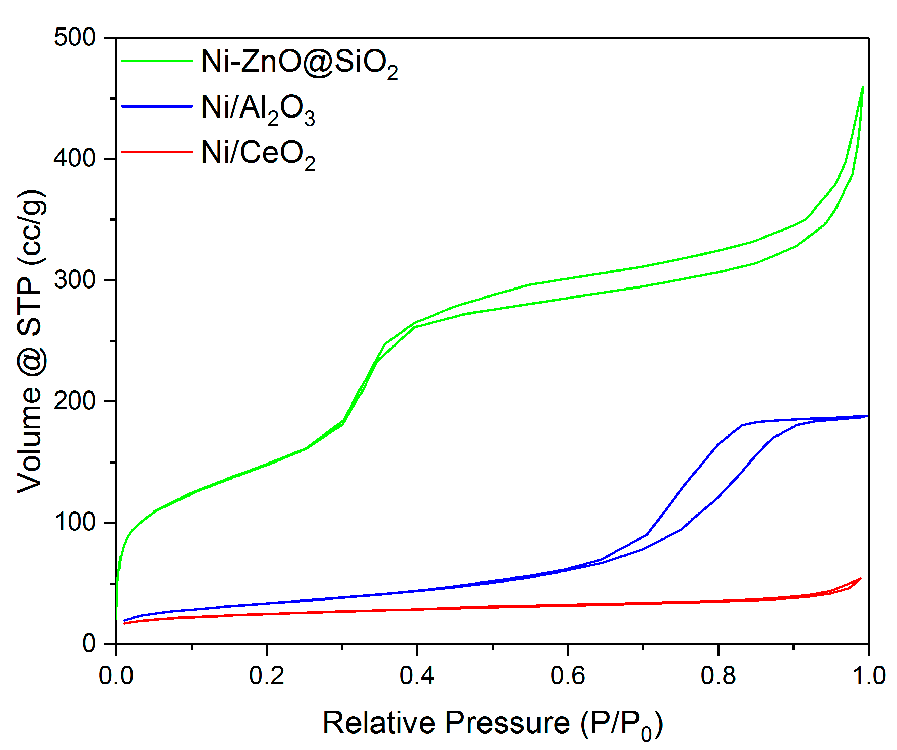
The N2 adsorption isotherms created for Ni/Al2O3 corresponds to that of a Type IV isotherms. This is characteristic for materials that develop mesopores. This is further supported via the pore diameter data calculated via the BJH method and shown in Table 1. All of the materials in this study feature pores greater than 2 nm, with values between 2–50 nm being considered as mesoporous. Ni/CeO2 displays a low volume type 2 isotherm, typical of materials with non-porous or macroporous materials. However, owing to the H3 hysteresis loop and the BJH data, this is in fact indicative of mesopores. The isotherm for Ni–ZnO@SiO2 (Figure 1) corresponds to that of a Type VI isotherm, which is characteristic of stepped multilayer adsorption, with the H3 hysteresis loop indicating slit shaped mesopores created by the overlapping and stacking of the Yolk shell particles, indicated by the H3 type hysteresis loop.
Further results have been determined from adsorption data via both the BET and BJH method are shown in Table 1. Surface area data obtained emphasizes that the introduction of a cerium support significantly reduces both the surface area and pore volume, compared to that of the benchmark support of alumina. The data established for Ni/CeO2 is in accordance with former experiments in literature, where it was found the addition of CeO2 significantly decreased the surface area of the catalyst, with the reduction dependent upon the amount of CeO2 [27]. Furthermore, reduction in pore volume suggests that nickel could be partially blocking the pores.
Overall, the reduction of the textural properties for Ni/CeO2 when compared to Ni/Al2O3 could significantly hinder the catalytic performance. However, the encapsulated Ni/ZnO provides a notable advantage when compared to non-encapsulated materials. This is apparent from the considerable increase in surface area and pore volume for Ni–ZnO@SiO2.
3.2. XRD
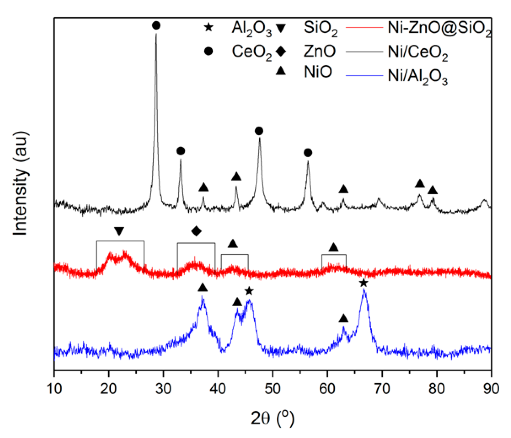
The XRD profiles of the catalytic materials used within this work clearly show the presence of NiO; peaks at 2θ values of 43° and 63° corresponding to NiO (2 0 0) and (2 2 0) planes. The Ceria supported catalyst exhibited further NiO peaks at 2θ values of 38°, 76° and 79° equivalent to NiO (1 1 1), (3 1 1) and (2 2 2), respectively (JCPDS No. 04-0850).
The alumina supported catalyst, excepting those mentioned above, shows a lack of NiO peaks. One explanation for this could be that the Ni was effectively distributed during impregnation, subsequently producing Ni particles of a size smaller than the restriction from the XRD equipment (typically smaller than 4 nm). The presence of a Ni-alumina spinel (NiAl2O4) cannot fully disregarded. Indeed, the development of this phase is hard to differentiate from the γ-Al2O3 as the diffraction lines overlap [38]. Crystalline peaks coinciding with the gamma phase planes (3 1 1) and (4 0 0) of alumina can be seen on Figure 2 at values 37°, 45° and 67° respectively (JCPDS No. 29-63). Ni/Ceria exhibit peaks at the typical diffraction lines of the cubic fluorite structured CeO2 at values 28°, 33°, 48° and 56°, corresponding to (1 1 1), (2 0 0), (2 2 0) and (3 1 1) (JCPDS No. 34-0394) [39].
The effects of the silica encapsulation can be seen in Figure 2, with the previously discussed NiO peaks at 43° and 63° being broad rather than sharp peaks that represent the (2 0 0) and (2 2 0) planes, as discussed previously. The interference of the shell is a major contributing factor to this peak broadening, especially considering that XRD is not an overly penetrating form of analysis. Another contributing factor the peak shape is that the Ni is well dispersed over the ZnO support.
3.3. SEM Analysis
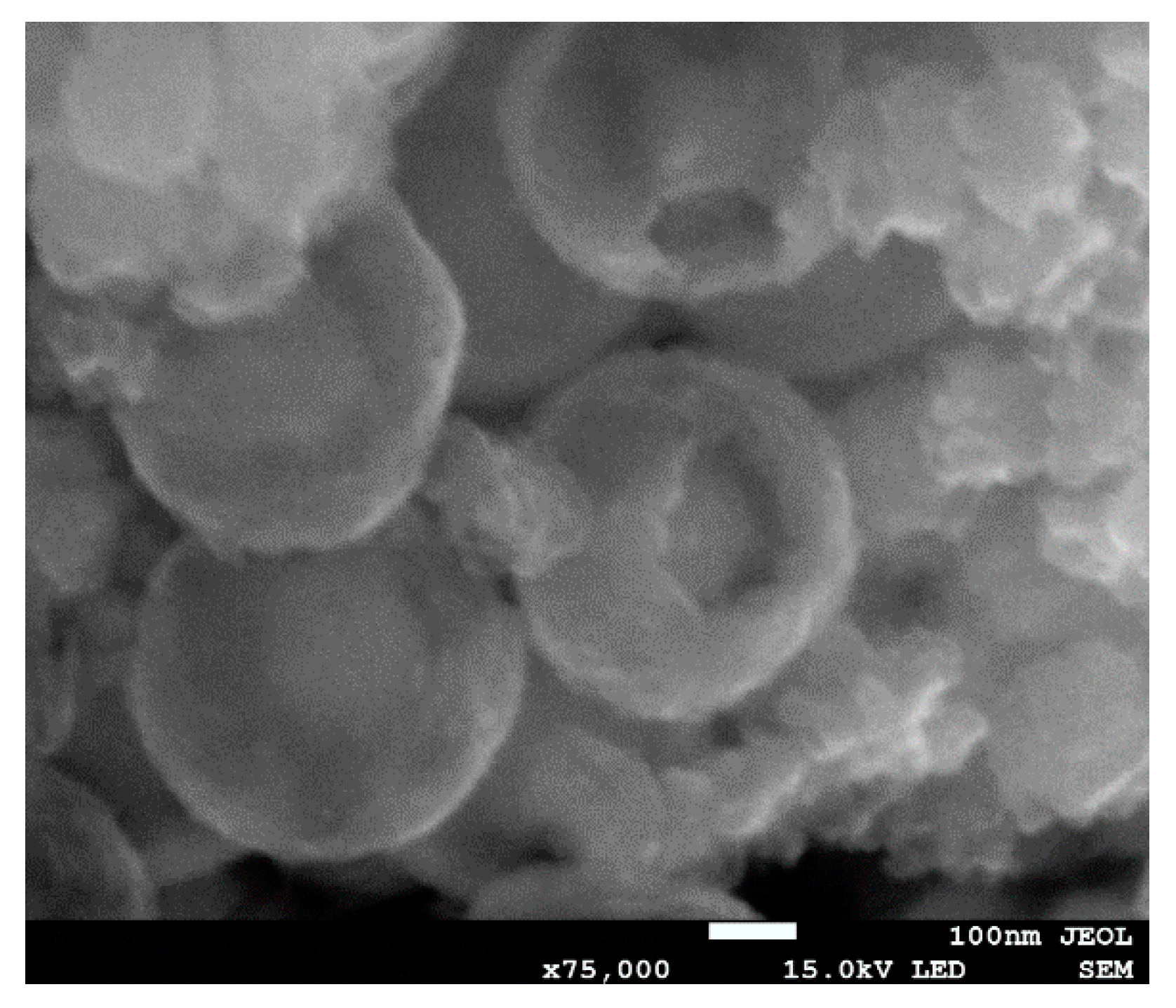
The clear evidence of successful encapsulation of the Ni/ZnO cores can be seen in Figure 3. The image depicts clearly, cores within larger silica shells with an approximate core size of 150 nm. This value is clearly larger than indicated by the XRD of this material, though this can be explained by limited agglomeration within the shell of the much smaller particles.
3.4. Catalytic Activity
The catalytic activity of all catalysts investigated within this report are compared to equilibrium values for the DRM produced from ChemStations’ ChemCad software package over the range of temperatures investigated within this work. The Soave–Redlich–Kwong equation of state was used in a Gibbs reactor with inlet material flows identical to those used for experimentation. Furthermore, all data points were found to be within ±0.5% error for the conversion data, as previously reported elsewhere [30].
3.5. Temperature Screening
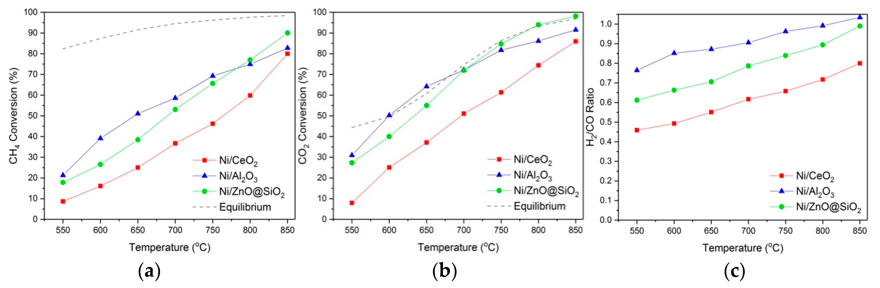
Given the endothermic nature of DRM, conversions of both CH4 and CO2 are evidently enhanced with an increase in reaction temperature as presented in Figure 4. Initially high CO2 conversions were observed for all catalysts compared to CH4, due to simultaneous occurrence of side reactions such as the RWGS (Equation (5)) and SRM (Equation (1)). Both the Ni–ZnO@SiO2 and Ni/Al2O3 performed significantly well throughout the temperature range with a steady conversion increase with temperature. Notably, both of these materials displayed multiple points of conversion above the equilibrium maximum, which is indicative of side reactions such as the RWGS reaction [40] occurring throughout the reaction. At higher temperatures however (T > 700 °C), the conversion of both CH4 and CO2 exhibited by the Ni/Al2O3 material fell beneath that shown by the Yolk-shell material.
Ni/CeO2, however, shows comparatively less catalytic activity throughout the entire temperature range. It is understood that for ceria supported catalysts, the initial conversion is primarily from the reactants’ disassociation on active metal particles. Yet, with increasing temperature the oxygen mobility from the ceria is enhanced with the lattice oxygen atoms being involved with CH4 conversion. This can be seen with a slower uptake of CH4 conversion between 550–650 °C when compared to Ni/Al2O3. Surface area could also be restricting the overall conversion performance, as highlighted in a previous section, the ceria supported catalyst has a surface area remarkably smaller than Ni/Al2O3 that presents superior conversion. This is one of the main weakness of using ceria as a support, with some studies using high surface area (HSA) ceria, for example CeO2–Al2O3 that combines the high surface area of alumina with the redox properties of CeO2 [27], as an alternative [41]. The ratio of H2/CO yield increases with growing reaction temperature for all catalysts, approaching 1 at higher temperatures which is the limit imposed by the nature of the reaction.
Notably, Ni/CeO2 has a lower ratio throughout the temperature range. Previously, the use of CeO2 has been demonstrated to catalyze the RWGS reaction which can be seen with the high CO2 conversion from these supported catalysts and the reduced H2/CO ratio [42].
The encapsulated catalyst Ni–ZnO@SiO2 performed significantly well at high temperature with conversions close to that of equilibrium for CH4 and reaching equilibrium for CO2 conversion. This shows the Yolk-shell material to be highly active within the DRM and unlike the Ni/Al2O3, shows no sign of deactivation as we will discuss in the next section. However, levels of conversion such as those demonstrated by our yolk shell material are not unheard of in supported metallic nanoparticles. The key improvement therefore, is the materials’ stability.
3.6. Stability Test
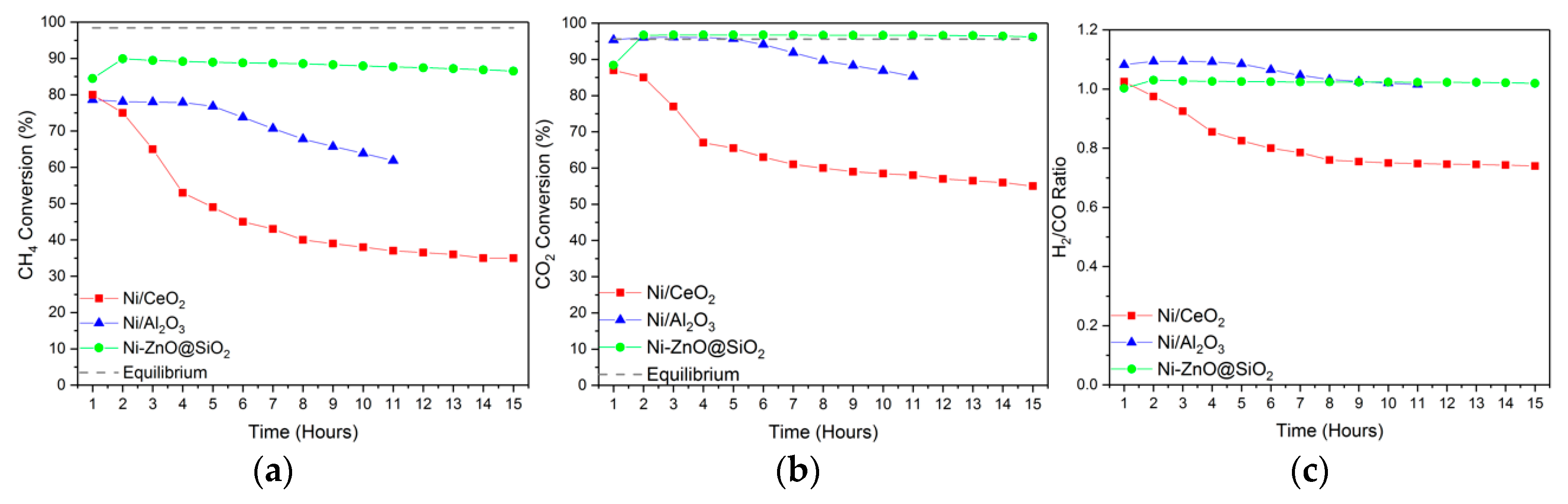
All synthesized samples endured DRM reaction at 850 °C for 15 h of continuous operation. We have selected this temperature despite its proximity to equilibrium conversion aiming to emulate industrial reforming units which typically run in the high temperature range (i.e., 850–1000 °C), where it is considered that reasonable levels of conversion can be attained with minimal detrimental effects to the catalyst through coking [41,43,44]. At this temperature, the possibility of deactivation via coking is significantly reduced compared to lower temperatures in good agreement with the reaction thermodynamics [31].
As displayed in Figure 5, Ni/Al2O3 and Ni–ZnO@SiO2 exhibit comparable levels of CO2 conversion for the first 5 h and while CH4 conversion was different, it remained comparable. The Ni/Al2O3 material then began to deactivate sharply until the experiment was terminated after 11 h, in good agreement with previous studies that shown that the acidic alumina support deactivates due to carbon deposition and sintering, which provides the reasoning for the research on the addition of promoters and additives [45,46].
In comparison, the ceria supported catalyst witnessed significant deactivation until finally beginning a plateau towards the culmination of the reaction.
Where the encapsulated material is concerned, it clearly benefits from its protective morphology; showing stable, high levels of conversion for both CH4 and CO2 for the duration of the experiment. These results evidence the superior behavior of the yolk-shell materials in terms of stability for the reforming of CO2/CH4 mixtures.
3.7. Post Reaction Analysis
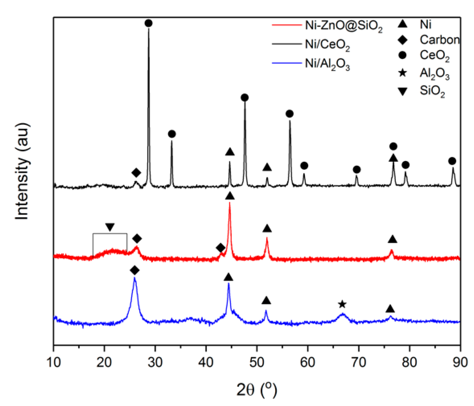
Following the recovery of the materials, XRD characterization determined the presence of carbon, which appeared as a peak at 26° on all samples and a second peak at 42° on the Ni/ZnO@SiO2 material that is indicative of the development of graphitic carbon (JCPDS No. 75-1621) (Figure 6) [47], as XRD analysis is unable to detect amorphous carbon. The development of this crystalline carbon agrees with previous research for alumina supported catalysts, where it found to be the conclusive deactivation mechanism [30,48] and is thought to be also caused by the decomposition of methane, especially considering our reaction temperature.
Due to this evidence, the rapid onset deactivation of the two conventional structured materials was reconciled to be directly caused by a cyclical action of sintering and carbon formation; it is well documented that the creation of larger Ni particles, in this case due to sintering, promotes the deposition of carbon.
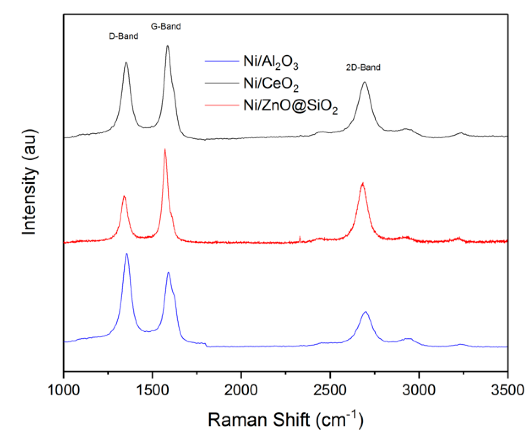
To further support the evidence found in the XRD results of the post reaction samples, Raman spectroscopy was undertaken to determine the nature of the coke deposits; the results of which can be seen in Figure 7. Clearly each spectra details the presence of the D, G and 2D bands that are expected for carbon at 1355, 1590 and 2700 cm−1, respectively [49,50]. The ID/IG ratios of each material were calculated to be 1.25, 0.83 and 0.54 for Ni/Al2O3, Ni/CeO2 and Ni/ZnO@SiO2 respectively. These ratios are significant as they indicate the nature of the formed carbon as a result of the catalysts application towards the DRM, with the D band corresponding to graphitic defects and is generated from the A1g phonon and the G band corresponds to the sp2 character of C–C bonding within graphitic lattices and is generated by the E2g phonon [30]. The coke formed on the Ni/Al2O3 catalyst is very different when compared to the other two catalysts, as can be seen by the ID/IG ratios, as it suggests the coke contains more defects within the graphitic deposit, as the ratio is greater than 1. However, the coke formed on the Ni/CeO2 and Ni/ZnO@SiO2 samples suggests a more pristine graphitic form of carbon deposit. The presence and size of the 2D band displayed by all three samples suggests layered graphitic sheets, which is further supported by the IG/I2D ratios of 1.58, 2.12 and 1.54 for Ni/CeO2, Ni/Al2O3 and Ni/ZnO@SiO2, respectively, which is indicative of multiple graphitic layers [51].
Following the analysis of the temperature screening data, apparent reaction rates were calculated aiming towards a more accurate comparison in terms of specific activity per mole of Ni. The results of these calculations can be found in Table 2.
From these results we can point out that Ni–ZnO@SiO2 maintains a significantly higher apparent rate of reaction across the three temperature intervals shown in Table 2, for both CO2 and CH4. This is significant as the Ni/ZnO@SiO2 material contained the least Ni content yet is shown to convert significantly more material per second. Furthermore, as the reaction rate for CO2 conversion always exceeds the rate of CH4 conversion for all three samples, it suggests that both the RWGS and SRM/BRM reactions were also favored under the conditions used for testing, which is supported by the >1 H2:CO ratio displayed by all catalysts during the initial stage of stability testing. Interestingly, the Ni/CeO2 material also displayed high apparent rates of reaction for both CH4 and CO2 (>650 °C), despite having the worst reactant conversions and life span during catalytic testing, which could be the effects of the well documented redox properties of CeO2 enabling these relatively high rates of reaction.
4. Conclusions
This work serves to demonstrate the advantages of Ni/ZnO@SiO2 Yolk shell particles over two traditional catalytic materials: Ni/CeO2 and Ni/Al2O3. All catalysts were successfully synthesized, characterized and applied within the DRM reaction for temperature screening and stability testing.
Despite the high surface area displayed by Al2O3 and the well documented redox properties of CeO2 towards preventing deactivation [52] while promoting CO2 activation, the incorporation of 15 wt.% Ni with these two supports in this work proved detrimental for the catalysts, with both materials demonstrating significant deactivation during the stability test as well as significantly lower reactant conversions and lower surface area of the catalyst when compared to the 8 wt.% Ni yolk shell material.
Following the stability tests, it is clear that the use of a protective porous shell enhances the effective lifespan of catalytic materials, while still promoting favorable conversion of both CO2 and CH4, with our yolk shell material demonstrating a lifespan far superior to the traditional Ni/Al2O3 and Ni/CeO2. These high levels of reactant conversion that were observed highlights the capability of encapsulated materials as DRM catalysts.
Overall, this work details that the benefits of encapsulating a catalytic core are not limited to significant increases to physical properties such as surface area, but extend to considerable improvements to reaction kinetics as well. The morphological variance explored in this work also found the Ni/ZnO@SiO2 to be a high-performance catalyst that displays a considerable increase in long term efficacy and high levels of reactant conversion. This therefore paves the way for further research and development of other catalysts or potential encapsulation techniques to address the challenge of global CO2 emissions via efficient catalytic processes.
Author Contributions
The experimental work and initial drafting was undertaken by both C.A.H.P. and E.E., with subsequent drafts being produced by the former author. Manuscript revisions, experimental and characterisational advice and undertaking was performed by L.P.-P., J.L. and T.R.R., with the latter author being lead supervisor for this work.
Acknowledgments
Financial and supervisory support for this work was provided by the Department of Chemical and Process Engineering at the University of Surrey, the Royal Society (Grant number RSGR1180353) and by the Australian Research Council (ARC) through Linkage Project program (LP150101158). This work was also partially sponsored by the CO2Chem through the EPSRC grant EP/P026435/1. LPP acknowledge Comunitat Valenciana for her APOSTD2017 fellowship. Sasol is kindly acknowledged for providing the alumina support.
Conflicts of Interest
The authors declare no conflict of interest.
References
- Pires, J.C.M.; Martins, F.G.; Alvim-Ferraz, M.C.M.; Simões, M. Recent developments on carbon capture and storage: An overview. Chem. Eng. Res. Des. 2011, 89, 1446–1460. [Google Scholar] [CrossRef]
- European Commission. SETIS Magazine, 2016; 52.
- Dry, M.E. The Fischer-Tropsch process: 1950–2000. Catal. Today 2002, 71, 227–241. [Google Scholar] [CrossRef]
- Ganesh, I. Conversion of carbon dioxide into methanol—A potential liquid fuel: Fundamental challenges and opportunities (a review). Renew. Sustain. Energy Rev. 2014, 31, 221–257. [Google Scholar] [CrossRef]
- Kumar, N.; Shojaee, M.; Spivey, J.J. Catalytic bi-reforming of methane: From greenhouse gases to syngas. Curr. Opin. Chem. Eng. 2015, 9, 8–15. [Google Scholar] [CrossRef]
- Gronchi, P.; Centola, P.; Del Rosso, R. Dry reforming of CH4 with Ni and Rh metal catalysts supported on SiO2 and La2O3. Appl. Catal. A Gen. 1997, 152, 83–92. [Google Scholar] [CrossRef]
- Farsi, A.; Mansouri, S.S. Influence of nanocatalyst on oxidative coupling, steam and dry reforming of methane: A short review. Arab. J. Chem. 2016, 9, S28–S34. [Google Scholar] [CrossRef] [Green Version]
- Santos, B.A.V.; Loureiro, J.M.; Ribeiro, A.M.; Rodrigues, A.E.; Cunha, A.F. Methanol production by bi-reforming. Can. J. Chem. Eng. 2015, 93, 510–526. [Google Scholar] [CrossRef]
- Choudhary, V.R.; Mondal, K.C.; Choudhary, T. V Oxy-CO2 Reforming of Methane to Syngas over CoOx/MgO/SA-5205 catalyst. Fuel 2006, 20, 2–5. [Google Scholar] [CrossRef]
- Arora, S.; Prasad, R. An overview on dry reforming of methane: Strategies to reduce carbonaceous deactivation of catalysts. RSC Adv. 2016, 6, 108668–108688. [Google Scholar] [CrossRef]
- Kaydouh, M.N.; El Hassan, N.; Davidson, A.; Casale, S.; El Zakhem, H.; Massiani, P. Effect of the order of Ni and Ce addition in SBA-15 on the activity in dry reforming of methane. C. R. Chim. 2015, 18, 293–301. [Google Scholar] [CrossRef]
- Nikoo, M.K.; Amin, N.A.S. Thermodynamic analysis of carbon dioxide reforming of methane in view of solid carbon formation. Fuel Process. Technol. 2011, 92, 678–691. [Google Scholar] [CrossRef] [Green Version]
- Behrens, M.; Armbrüster, M. Catalysis for Alternative Energy Generation—Methanol Steam Reforming. In Catalysis for Alternative Energy Generation; Springer: New York, NY, USA, 2012; pp. 175–235. ISBN 978-1-4614-0343-2. [Google Scholar]
- Rostrup-Nielsen, J.R. Industrial relevance of coking. Catal. Today 1997, 37, 225–232. [Google Scholar] [CrossRef]
- Guharoy, U.; Le Saché, E.; Cai, Q.; Reina, T.R.; Gu, S. Understanding the role of Ni-Sn interaction to design highly effective CO2 conversion catalysts for dry reforming of methane. J. CO2 Util. 2018, 27, 1–10. [Google Scholar] [CrossRef]
- Seo, H. Recent Scientific Progress on Developing Supported Ni Catalysts for Dry (CO2) Reforming of Methane. Catalysts 2018, 8, 110. [Google Scholar] [CrossRef]
- Charisiou, N.D.; Siakavelas, G.; Papageridis, K.N.; Baklavaridis, A.; Tzounis, L.; Avraam, D.G.; Goula, M.A. Syngas production via the biogas dry reforming reaction over nickel supported on modified with CeO2 and/or La2O3 alumina catalysts. J. Nat. Gas Sci. Eng. 2016, 31, 164–183. [Google Scholar] [CrossRef]
- Sehested, J.; Gelten, J.A.P.; Helveg, S. Sintering of nickel catalysts: Effects of time, atmosphere, temperature, nickel-carrier interactions, and dopants. Appl. Catal. A Gen. 2006, 309, 237–246. [Google Scholar] [CrossRef]
- Alotaibi, R.; Alenazey, F.; Alotaibi, F.; Wei, N.; Al-Fatesh, A.; Fakeeha, A. Ni catalysts with different promoters supported on zeolite for dry reforming of methane. Appl. Petrochem. Res. 2015, 5, 329–337. [Google Scholar] [CrossRef] [Green Version]
- Valentini, A.; Carreño, N.L.V.; Probst, L.F.D.; Lisboa-Filho, P.N.; Schreiner, W.H.; Leite, E.R.; Longo, E. Role of vanadium in Ni:Al2O3 catalysts for carbon dioxide reforming of methane. Appl. Catal. A Gen. 2003, 255, 211–220. [Google Scholar] [CrossRef]
- Wang, M.; Boyjoo, Y.; Pan, J.; Wang, S.; Liu, J. Advanced yolk-shell nanoparticles as nanoreactors for energy conversion. Cuihua Xuebao/Chin. J. Catal. 2017, 38, 970–990. [Google Scholar] [CrossRef]
- Li, Z.; Li, M.; Bian, Z.; Kathiraser, Y.; Kawi, S. Design of highly stable and selective core/yolk-shell nanocatalysts-review. Appl. Catal. B Environ. 2016, 188, 324–341. [Google Scholar] [CrossRef]
- Yang, W.; Liu, H.; Li, Y.; Zhang, J.; Wu, H.; He, D. Properties of yolk-shell structured Ni@SiO2 nanocatalyst and its catalytic performance in carbon dioxide reforming of methane to syngas. Catal. Today 2016, 259, 438–445. [Google Scholar] [CrossRef]
- Wang, F.; Xu, L.; Shi, W. Syngas production from CO2 reforming with methane over core-shell Ni@SiO2 catalysts. J. CO2 Util. 2016, 16, 318–327. [Google Scholar] [CrossRef]
- Das, S.; Ashok, J.; Bian, Z.; Dewangan, N.; Wai, M.H.; Du, Y.; Borgna, A.; Hidajat, K.; Kawi, S. Silica–Ceria sandwiched Ni core–shell catalyst for low temperature dry reforming of biogas: Coke resistance and mechanistic insights. Appl. Catal. B Environ. 2018, 230, 220–236. [Google Scholar] [CrossRef]
- Zhao, X.; Li, H.; Zhang, J.; Shi, L.; Zhang, D. Design and synthesis of NiCe@m-SiO2 yolk-shell framework catalysts with improved coke- and sintering-resistance in dry reforming of methane. Int. J. Hydrogen Energy 2016, 41, 2447–2456. [Google Scholar] [CrossRef]
- Damyanova, S.; Bueno, J.M.C. Effect of CeO2 loading on the surface and catalytic behaviors of CeO2-Al2O3-supported Pt catalysts. Appl. Catal. A Gen. 2003, 253, 135–150. [Google Scholar] [CrossRef]
- Verykios, X.E. Mechanistic aspects of the reaction of CO2 reforming of methane over Rh/Al2O3 catalyst. Appl. Catal. A Gen. 2003, 255, 101–111. [Google Scholar] [CrossRef]
- Pines, H.; Haag, W.O. Alumina: Catalyst and Support. I. Alumina, Its Intrinsic Acidity and Catalytic Activity. J. Am. Chem. Soc. 1960, 82, 2471–2483. [Google Scholar] [CrossRef]
- Stroud, T.; Smith, T.J.; Le Saché, E.; Santos, J.L.; Centeno, M.A.; Arellano-Garcia, H.; Odriozola, J.A.; Reina, T.R. Chemical CO2 recycling via dry and bi reforming of methane using Ni-Sn/Al2O3 and Ni-Sn/CeO2-Al2O3 catalysts. Appl. Catal. B Environ. 2018, 224, 125–135. [Google Scholar] [CrossRef]
- Djinović, P.; Batista, J.; Pintar, A. Efficient catalytic abatement of greenhouse gases: Methane reforming with CO2 using a novel and thermally stable Rh-CeO2 catalyst. Int. J. Hydrogen Energy 2012, 37, 2699–2707. [Google Scholar] [CrossRef]
- Le Saché, E.; Pastor-Pérez, L.; Watson, D.; Sepúlveda-Escribano, A.; Reina, T.R. Ni stabilised on inorganic complex structures: Superior catalysts for chemical CO2 recycling via dry reforming of methane. Appl. Catal. B Environ. 2018, 236, 458–465. [Google Scholar] [CrossRef]
- Liu, J.; Qiao, S.Z.; Chen, J.S.; Lou, X.W.; Xing, X.; Lu, G.Q. Yolk/shell nanoparticles: New platforms for nanoreactors, drug delivery and lithium-ion batteries. Chem. Commun. 2011, 47, 12578. [Google Scholar] [CrossRef] [PubMed]
- Ding, C.; Ai, G.; Zhang, K.; Yuan, Q.; Han, Y.; Ma, X.; Wang, J.; Liu, S. Coking resistant Ni/ZrO2@SiO2 catalyst for the partial oxidation of methane to synthesis gas. Int. J. Hydrogen Energy 2015, 40, 6835–6843. [Google Scholar] [CrossRef]
- Zhang, J.; Li, F. Coke-resistant Ni at SiO2 catalyst for dry reforming of methane. Appl. Catal. B Environ. 2015, 176–177, 513–521. [Google Scholar] [CrossRef]
- Kim, D.H.; Kim, S.Y.; Han, S.W.; Cho, Y.K.; Jeong, M.G.; Park, E.J.; Kim, Y.D. The catalytic stability of TiO2-shell/Ni-core catalysts for CO2 reforming of CH4. Appl. Catal. A Gen. 2015, 495, 184–191. [Google Scholar] [CrossRef]
- Baktash, E.; Littlewood, P.; Schomäcker, R.; Thomas, A.; Stair, P.C. Alumina coated nickel nanoparticles as a highly active catalyst for dry reforming of methane. Appl. Catal. B Environ. 2015, 179, 122–127. [Google Scholar] [CrossRef]
- Luisetto, I.; Tuti, S.; Battocchio, C.; Lo Mastro, S.; Sodo, A. Ni/CeO2-Al2O3 catalysts for the dry reforming of methane: The effect of CeAlO3 content and nickel crystallite size on catalytic activity and coke resistance. Appl. Catal. A Gen. 2015, 500, 12–22. [Google Scholar] [CrossRef]
- Ay, H.; Üner, D. Dry reforming of methane over CeO2 supported Ni, Co and Ni-Co catalysts. Appl. Catal. B Environ. 2015, 179, 128–138. [Google Scholar] [CrossRef]
- Daza, Y.A.; Kent, R.A.; Yung, M.M.; Kuhn, J.N. Carbon dioxide conversion by reverse water-gas shift chemical looping on perovskite-type oxides. Ind. Eng. Chem. Res. 2014, 53, 5828–5837. [Google Scholar] [CrossRef]
- Laosiripojana, N.; Assabumrungrat, S. Catalytic dry reforming of methane over high surface area ceria. Appl. Catal. B Environ. 2005, 60, 107–116. [Google Scholar] [CrossRef]
- Kovacevic, M.; Mojet, B.L.; Van Ommen, J.G.; Lefferts, L. Effects of Morphology of Cerium Oxide Catalysts for Reverse Water Gas Shift Reaction. Catal. Lett. 2016, 146, 770–777. [Google Scholar] [CrossRef] [Green Version]
- Abdullah, B.; Abd Ghani, N.A.; Vo, D.V.N. Recent advances in dry reforming of methane over Ni-based catalysts. J. Clean. Prod. 2017, 162, 170–185. [Google Scholar] [CrossRef]
- De Falco, M.; Iaquaniello, G.; Centi, G. CO2: A valuable source of carbon. Green Energy Technol. 2013, 137, 194. [Google Scholar] [CrossRef]
- Bereketidou, O.A.; Goula, M.A. Biogas reforming for syngas production over nickel supported on ceria-alumina catalysts. Catal. Today 2012, 195, 93–100. [Google Scholar] [CrossRef]
- Hou, Z.; Yokota, O.; Tanaka, T.; Yashima, T. Characterization of Ca-promoted Ni/α-Al2O3 catalyst for CH4 reforming with CO2. Appl. Catal. A Gen. 2003, 253, 381–387. [Google Scholar] [CrossRef]
- Wolfbeisser, A.; Sophiphun, O.; Bernardi, J.; Wittayakun, J.; Föttinger, K.; Rupprechter, G. Methane dry reforming over ceria-zirconia supported Ni catalysts. Catal. Today 2016, 277, 234–245. [Google Scholar] [CrossRef]
- Seok, S.H.; Sun, H.C.; Park, E.D.; Sung, H.H.; Jae, S.L. Mn-promoted Ni/Al2O3 catalysts for stable carbon dioxide reforming of methane. J. Catal. 2002, 209, 6–15. [Google Scholar] [CrossRef]
- Bokobza, L.; Bruneel, J.L.; Couzi, M. Raman spectroscopy as a tool for the analysis of carbon-based materials (highly oriented pyrolitic graphite, multilayer graphene and multiwall carbon nanotubes) and of some of their elastomeric composites. Vib. Spectrosc. 2014, 74, 57–63. [Google Scholar] [CrossRef]
- Childres, I.; Jauregui, L.A.; Park, W.; Cao, H.; Chena, Y.P. Raman Spectroscopy of Graphene and Related Materials. Front. Mol. Spectrosc. 2009, 553–595. [Google Scholar] [CrossRef]
- Lehman, J.H.; Terrones, M.; Mansfield, E.; Hurst, K.E.; Meunier, V. Evaluating the characteristics of multiwall carbon nanotubes. Carbon N. Y. 2011, 49, 2581–2602. [Google Scholar] [CrossRef]
- Price, C.; Pastor-Pérez, L.; le Saché, E.; Sepúlveda-Escribano, A.; Reina, T.R. Highly active Cu-ZnO catalysts for the WGS reaction at medium–high space velocities: Effect of the support composition. Int. J. Hydrogen Energy 2017, 42, 10747–10751. [Google Scholar] [CrossRef] [Green Version]
Figure 1.
N2 adsorption isotherm for the Ni–ZnO@SiO2.

Figure 2.
XRD patterns for all catalysts, pre-activation.

Figure 3.
SEM image of the Ni–ZnO@SiO2 confirming the morphology of the encapsulated material.

Figure 4.
DRM Temperature screening results for (a) CH4 and (b) CO2 conversion and (c) the product ratio for all samples between 550–850 °C, WHSV = 30 L gcat−1 h−1 and a reactant ratio CH4:CO2 = 1:1.
Figure 4.
DRM Temperature screening results for (a) CH4 and (b) CO2 conversion and (c) the product ratio for all samples between 550–850 °C, WHSV = 30 L gcat−1 h−1 and a reactant ratio CH4:CO2 = 1:1.

Figure 5.
A 15 h stability test results concerning (a) CH4 and (b) CO2 conversion and (c) product ratio for all samples within the DRM reaction at 850 °C, WHSV = 30 L gcat−1 h−1 and a reactant ratio CH4:CO2 = 1:1.
Figure 5.
A 15 h stability test results concerning (a) CH4 and (b) CO2 conversion and (c) product ratio for all samples within the DRM reaction at 850 °C, WHSV = 30 L gcat−1 h−1 and a reactant ratio CH4:CO2 = 1:1.

Figure 6.
Comparative XRD analysis of all samples post reaction.

Figure 7.
Raman spectra obtained for all post-reaction samples.


Table 1.
Textural characteristics established for all catalysts investigated, as calculated by BET and BJH analysis.
Table 1.
Textural characteristics established for all catalysts investigated, as calculated by BET and BJH analysis.
| Sample | SBET (m2g−1) | Vpore (cm3g−1) | DPore (nm) |
|---|---|---|---|
| Ni/Al2O3 | 158 | 0.40 | 6.8 |
| Ni/CeO2 | 81 | 0.06 | 3.3 |
| Ni–ZnO@SiO2 | 700 | 0.55 | 2.6 |
Table 2.
Apparent reaction rates (R) of the catalysts tested within this study.
| Sample | R550 CH4 (molconv.s−1/moleNi) | R650 CH4 (molconv.s−1/moleNi) | R800 CH4 (molconv.s−1/moleNi) | R550 CO2 (molconv.s−1/moleNi) | R650 CO2 (molconv.s−1/moleNi) | R800 CO2 (molconv.s−1/moleNi) |
|---|---|---|---|---|---|---|
| Ni–ZnO@SiO2 | 1.09 | 2.24 | 4.56 | 1.64 | 3.18 | 5.55 |
| Ni/CeO2 | 0.42 | 1.21 | 2.89 | 0.42 | 1.99 | 3.98 |
| Ni/Al2O3 | 0.84 | 1.03 | 1.33 | 1.22 | 1.43 | 1.78 |
© 2018 by the authors. Licensee MDPI, Basel, Switzerland. This article is an open access article distributed under the terms and conditions of the Creative Commons Attribution (CC BY) license (http://creativecommons.org/licenses/by/4.0/).
Share and Cite
MDPI and ACS Style
Price, C.A.H.; Earles, E.; Pastor-Pérez, L.; Liu, J.; Reina, T.R. Advantages of Yolk Shell Catalysts for the DRM: A Comparison of Ni/ZnO@SiO2 vs. Ni/CeO2 and Ni/Al2O3. Chemistry 2019, 1, 3-16. https://doi.org/10.3390/chemistry1010003
AMA Style
Price CAH, Earles E, Pastor-Pérez L, Liu J, Reina TR. Advantages of Yolk Shell Catalysts for the DRM: A Comparison of Ni/ZnO@SiO2 vs. Ni/CeO2 and Ni/Al2O3. Chemistry. 2019; 1(1):3-16. https://doi.org/10.3390/chemistry1010003
Chicago/Turabian StylePrice, Cameron Alexander Hurd, Emily Earles, Laura Pastor-Pérez, Jian Liu, and Tomas Ramirez Reina. 2019. "Advantages of Yolk Shell Catalysts for the DRM: A Comparison of Ni/ZnO@SiO2 vs. Ni/CeO2 and Ni/Al2O3" Chemistry 1, no. 1: 3-16. https://doi.org/10.3390/chemistry1010003