
Process Intensification Strategies for Power-to-X Technologies


1
Fraunhofer Institute for Solar Energy Systems ISE, Heidenhofstraße 2, 79110 Freiburg im Breisgau, Germany
2
Institute for Chemical Engineering, Ulm University, Albert-Einstein-Allee 11, 89081 Ulm, Germany
*
Author to whom correspondence should be addressed.
ChemEngineering 2022, 6(1), 13; https://doi.org/10.3390/chemengineering6010013
Submission received: 9 December 2021
/
Revised: 5 January 2022
/
Accepted: 24 January 2022
/
Published: 2 February 2022
(This article belongs to the Special Issue Process Intensification for Chemical Engineering and Processing)
Abstract
:Sector coupling remains a crucial measure to achieve climate change mitigation targets. Hydrogen and Power-to-X (PtX) products are recognized as major levers to allow the boosting of renewable energy capacities and the consequent use of green electrons in different sectors. In this work, the challenges presented by the PtX processes are addressed and different process intensification (PI) strategies and their potential to overcome these challenges are reviewed for ammonia (NH3), dimethyl ether (DME) and oxymethylene dimethyl ethers (OME) as three exemplary, major PtX products. PI approaches in this context offer on the one hand the maximum utilization of valuable renewable feedstock and on the other hand simpler production processes. For the three discussed processes a compelling strategy for efficient and ultimately maintenance-free chemical synthesis is presented by integrating unit operations to overcome thermodynamic limitations, and in best cases eliminate the recycle loops. The proposed intensification processes offer a significant reduction of energy consumption and provide an interesting perspective for the future development of PtX technologies.

1. Introduction
Code red for humanity was addressed in the recent intergovernmental panel for climate change IPCC report published in summer 2021 [1]. The emerging issue of climate change enforces the drastic reduction of greenhouse gas emissions. Electrification by boosting of renewable energy capacities to supply all energy demanding economic sectors is necessary to reach the defined climate change mitigation targets [2]. The production of green hydrogen (H2) using renewable energy and the subsequent synthesis of chemicals in Power-to-X (PtX) processes was identified as an important pillar for sector coupling and for the transformation towards a sustainable energy system [3]. PtX is defined as the integration of renewable energy beyond direct electrification into the energy, mobility, industry and private sectors via H2 based renewable energy carriers [4]. The production and import of renewable energy from locations with a high potential will be a crucial element of the future energy system and will inevitably require a suitable energy carrier. All long-distance and heavy duty transportation will rely to a large extent on dense liquid fuels in the future [5]. Regarding the German energy market, the annual demand for energy in the form of PtX molecules is estimated to range from 75 up to 500 TWh by 2050 [5,6]. Possible products of PtX processes vary from synthetic fuels such as E-diesel or E-kerosene, to common bulk chemicals like methanol (MeOH) and ammonia (NH3), and further to highly processed chemicals and oxygenated fuels like dimethyl ethers (DME) or oxymethylene dimethyl ethers (OME).
1.1. Boundary Conditions for PtX Processes
One of the main challenges of renewable energy-based processes is the geographically dependent potential and temporal fluctuation of renewable resources and consequently fluctuating electricity production. Green H2 production based on these fluctuating green electrons is technologically possible via water electrolysis, which is subsequently used as the feedstock for synthetic fuels, chemicals and energy carrier production. Since steady-state operation is the common strategy in conventional large-scale chemical or refinery processes, new operational strategies are needed. Available strategies are either the storage of H2 under elevated pressure or cryogenic conditions or alternatively, to operate the downstream process dynamically, a major emerging challenge for these industries. However, H2 storage remains energy intensive and expensive. For instance, the cost for storage can reach up to a 25% share of the net production cost (NPC) of H2 production in small and medium size systems [7]. Furthermore, proposed large scale H2 storage technologies such as salt caverns, are scarce and not necessarily available at locations rich in renewable resources [8]. In the light of the previous discussion, the latter strategy of dynamic PtX process operation can minimize and ultimately avoid H2 storage allowing for significant NPC reduction. A dynamic process in the context of this work refers to the possibility to control the process conditions and plant utilization based on the availability of renewable energy. However, the dynamic operation of reactors, compressors and other unit operations exhibit challenges that require investigation and further development. For the example of heterogeneously catalyzed exothermic reactions performed in fixed-bed reactors some of these major challenges are:
- (a)
- the thermal instability and transient hot spot formation,
- (b)
- the possibly enhanced catalyst deactivation and degradation due to thermal cycling and load changes,
- (c)
- and the transient changes in product quality or composition and possible undesired side product formation.
Locations with high potential for renewable energy production are often located in remote areas without connection to the infrastructure available at industrialized areas or even offshore. The realization of chemical processes at remote locations without grid connection presents several additional challenges, such as:
- (a)
- no compensation of fluctuating electricity using grid electricity,
- (b)
- the elaborative production of utilities onsite using renewable resources,
- (c)
- the high costs of operation and maintenance,
- (d)
- and the limited available area for construction.
Moreover, from an economic point of view, the usage of green H2 emphasizes the need for highest material and energy efficiency of PtX processes. This was supported by recent studies investigating the production of different PtX products which revealed that green H2 production costs represented more than 60% of the NPC of various PtX products [9].
1.2. Objectives of This Work
In this work, the arising challenges for PtX processes are addressed for three important PtX products namely: NH3, DME and OME. Process intensification (PI) strategies suitable for these heterogeneously catalyzed thermochemical processes are introduced. Moreover, the state-of-the-art is briefly discussed followed by the introduction of the most promising examples for improving the respective process via PI based on recent literature. The potential of PI methods for combining heterogeneously catalyzed reactions and the subsequent separation processes aiming to shift the thermodynamic equilibrium towards the desired products is identified and discussed. Emphasis is placed on quantification of the improvements obtained by PI, to evaluate the potential of respective measures.
1.3. Background and Process Intensification Approaches
Since the term “Process Intensification” is not defined consistently and the variety of PI approaches remains wide, a short definition and the understanding of PI in the present work is provided as follows. The motivation for the development of PI technologies is described as “doing more with less” by Jenck et al. [10], comprehensively leading to an increased process efficiency as the overall goal of PI approaches. Stankiewicz et al., define PI as “any chemical engineering development that leads to a substantially smaller, cleaner, and more energy efficient technology”, which result in a “cheaper and sustainable” technology [11]. According to Ramshaw et al., PI is a strategy for making “dramatic reductions in the size of a chemical plant to reach a given production objective” [12]. Van Annalandt et al., investigated into PI for PtX products and concluded that the application of PI to the energy sector can result in a dramatic decrease in the production of waste, including greenhouse gas emissions [13].
For a better overview, the categorization of PI approaches into (a) process-intensifying equipment and (b) process-intensifying methods was proposed in the literature [14]. The process-intensifying methods describe novel process concepts, such as hybrid separations or the usage of alternative energy forms or sources [15]. As chemical reactions and the chemical reactor represent the centerpiece of most chemical processes, PI methods often focus on this process unit [16]. Most importantly for the scope of this work, the integration of several unit operations into multifunctional reactors provides a promising approach of the process intensifying methods. Multifunctional reactors combine the reaction with another unit operation that would conventionally take place in a separate process apparatus. For instance, the removal of a reaction product or by-product in the reactor can decrease kinetic or thermodynamic limitations and accordingly enhance the reaction regarding selectivity and conversion. Due to the increasing conversion, recycle streams and required equipment can be avoided, which consequently allows for a reduction in the number of process units by the integration of multiple process units within the multifunctional chemical reactor [16]. Additionally, a lower demand in utilities can offer an important benefit of a highly intensified process.
2. Process Intensification for Power-to-Ammonia Processes
2.1. Background
NH3 is one of the most produced chemicals globally, with a production rate of 150 Mt/a in 2019. In addition to the current importance of NH3 as a base chemical, its usage as a chemical energy storage molecule in the Power-to-Ammonia (PtA) process is discussed extensively in the scientific literature and in recent political scenarios [17]. This is due to the fact, that compared to pure H2, NH3 exhibits a high volumetric energy density and lower costs for storage in the liquid phase under comparatively mild conditions [18]. Thereby, either a low-temperature storage at −33 °C under ambient pressure or a pressurized storage at around 16 bar under ambient temperature is possible [19]. NH3 is synthesized from N2 and H2 according to the stoichiometric Equation (1), whereby the synthesis conditions are defined by the reversible, exothermic nature of the reaction. With respect to the raw materials, NH3 can indirectly be produced from air and water by using atmospheric N2 from air and green H2 produced via water electrolysis in a PtX scenario. Compared to other PtX processes, the PtA process does not require a carbon source, providing the NH3 production with a unique flexibility in various locations [20].
Furthermore, NH3 can be used flexibly as a CO2 free fuel in fuel cells [21] or combustion engines [22], as a H2 carrier [23] or as a base chemical (i.e., in fertilizer production). State-of-the-art NH3 production is based on fossil H2 produced from natural gas via steam reforming. In this process large amounts of CO2 are emitted. Consequently, the global scale of NH3 production based on a fossil feedstock constitutes almost 2% of global CO2 emissions and the decarbonization of the conventional Haber–Bosch process provides an immense potential for reduction of CO2 emissions [24].
2.2. Conventional Haber-Bosch Process
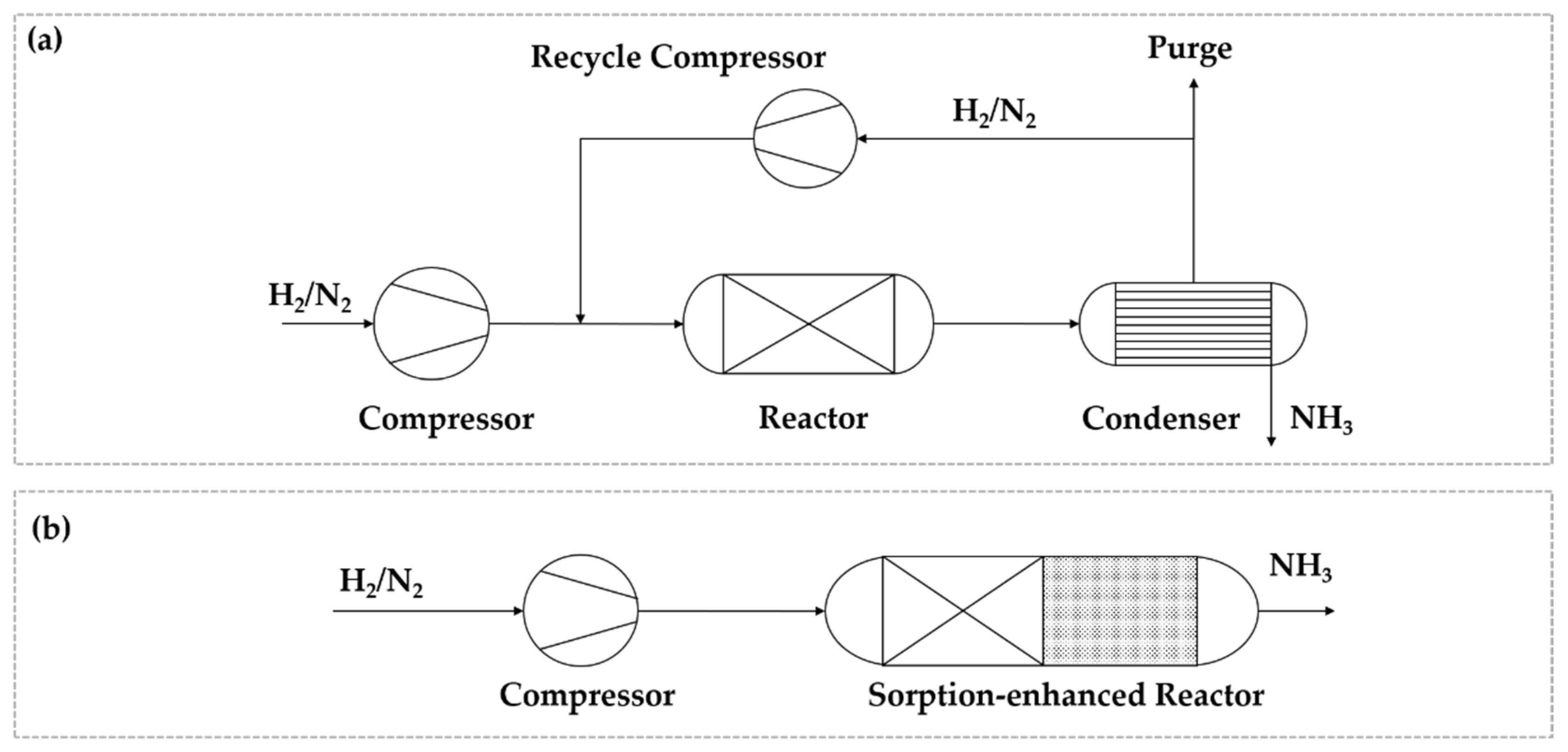
NH3 synthesis is performed based on the Haber–Bosch process developed in the beginning of the 20th century. The main process units comprise the compressors for synthesis and recycle gas, the NH3 reactor and the condensation unit to remove NH3 from non-converted reactant gases as shown in Figure 1a. The process is characterized by its harsh temperature and pressure conditions required for synthesis at pressures between 100–300 bar and temperatures above 450 °C. Reaction conditions are defined by the commonly used multi-promoted, magnetite-based iron catalysts [25]. To reach sufficient kinetic activity high temperatures are needed. In consequence, the synthesis pressures need to be increased, to shift the chemical equilibrium towards NH3 formation [26]. Due to the advantages of these catalysts, such as low costs and high structural stability under harsh reaction conditions, industrial relevance for other catalytic materials is low [27]. Increasing the production scale and a high degree of energy integration led to a drastic reduction of energy demand of modern Haber–Bosch processes. Recent world-scale plants produce NH3 from natural gas as the H2 source with a specific energy demand of around 28 GJ per ton of NH3 and an overall process energy efficiency of up to 70% [28].
2.3. Power-to-Ammonia
The term PtA is used for NH3 synthesis processes based on renewable energy, whereby the reactant H2 is produced via water electrolysis, while N2 is provided via air separation technologies. The production of NH3 from renewable H2 was successfully demonstrated on a pilot-scale [29]. An overview of existing and planned demonstration plants was given by Ayvali and co-workers [30]. The ongoing research into PtA technology can be categorized mainly into two pathways [31]. The first pathway describes the implementation of the conventional Haber–Bosch process loop into a process based on renewable H2 feedstock. This concept is mainly discussed for the world-scale production of NH3 and the reutilization of existing production plants with H2 derived from renewable sources. The second pathway is research-driven and focuses on non-conventional and enhanced production technologies. The focus is on overcoming the described challenges of PtX processes to increase the process efficiency for decentralized NH3 production units. In this context considered PI methods and their potential are described in the following sections.
2.4. Process Intensification Methods
The heterogeneously catalyzed reaction is the centerpiece of the synthesis process and defines the operation conditions for further unit operations. Therefore, the investigation towards highly active catalysts was part of the research and development in the course of the century of industrial NH3 synthesis. This led to a high number of different active, promoter and support materials, which were investigated. Ruthenium-based catalysts were identified as a promising material for NH3 synthesis under milder reaction conditions due to their high catalytic activity [32]. Recent studies showed that the synthesis of NH3 at pressures below 10 bar and at temperatures between 300 and 400 °C was feasible [33,34], which provided a decrease in energy demand (i.e., for synthesis gas compression). Furthermore, a fast response and a high stability towards the thermal cycling was demonstrated [35]. This is necessary for dynamically operated NH3 reactors for renewable feedstock conversion in remote locations. Accordingly, the usage of Ru-based catalysts and the associated shift towards mild reaction conditions is expected to be an important contribution for the aimed PI.
If NH3 is synthesized at a lower pressure, the operating conditions for the separation of NH3 changes. Since the partial pressure of NH3 in the product gas decreases due to lower NH3 equilibrium concentration and the lower total pressure, lower temperatures for condensation are necessary. Therefore, the energy demand for separation via condensation in low-pressure processes increases, while separation efficiency decreases [36]. Importantly, the complete separation of NH3 is crucial for the process energy efficiency, as NH3 remaining in the recycle stream leads to a decrease in the formation rate due to unfavorable equilibrium constraints [37]. To overcome this challenge, the replacement of condensation with adsorptive or absorptive NH3 separation for low pressure processes was discussed as a promising option in various publications [38,39,40,41,42,43,44,45,46,47]. These techniques, which can be carried out at elevated temperatures, provide a selective separation of NH3 and can reach a low residual NH3 concentration in the recycle stream (<1%) [31]. Furthermore, the energy demand for the latter separation approach is rather low.
Various materials for the sorption of NH3 are available, whereby the research focuses on zeolitic materials [40] and metal halide salts [48]. The main challenge arises from the fact that ad-/absorbed NH3 needs to be released in an additional pressure or temperature swing process (PSA/TSA). The full release of the adsorbed NH3 and the stability of the adsorbent under the periodic operation remain undergoing research topics for sorptive NH3 separation [44]. A further promising PI method is the process integration of the reactor and a sorption-based separation process into a single multifunctional reactor, as described in Figure 1b. The in situ removal of the reaction product shifts the equilibrium towards the product site and mitigates the thermodynamic limitation of the synthesis even at a low pressure. Moreover, the sorptive in situ removal replaces the inefficient condensation of NH3 at a low pressure. First approaches for the realization of a multifunctional reactor using a Ru-based catalyst for NH3 synthesis and metal halide salts for separation were published recently [41].
The potential of the PI strategies discussed above are compared quantitatively with respect to the specific energy demand per ton of liquid NH3 produced as published in the recent literature ([31,37,49]). Figure 2 shows the energy demands for synthesis and recycle gas compression, as well as for cooling in the condenser. A conventional Haber–Bosch process is compared with a low-pressure synthesis process, a process with sorptive separation and a process with in situ separation.
As discussed above, more active catalysts allow for lower operation pressure. The comparison therefore illustrates the effect of novel catalysts in conventional process concepts. For conventional processes operating at 300 bar, the specific energy demand is mainly caused by the compression of the synthesis gas and amounts to around 6 GJ/t [37]. The reduction of the pressure to 100 bar leads to a decrease in overall energy demand [50]. At mild pressures of 20 bar the energy demand surprisingly increases drastically, mainly driven by the energy intensive condensation of the produced NH3 at lower temperatures compared to conventional processes [49]. Replacing the condensation with an adsorptive separation downstream the NH3 synthesis reactor allows for a significant decrease in energy demand at the low synthesis pressure of 20 bar [31,51]. For the integrated process with in situ NH3 separation, a further reduction of energy demand down to around 3 GJ/t can be expected according to Smith et al. [49], including the energy demand for desorption via a temperature swing process and the liquefaction of desorbed ammonia. This integrated process clearly outperforms the conventional one. The main reason is the shift in equilibrium constraints provided by the high catalyst activity at low temperatures combined with the in situ removal of the reaction product NH3. Thereby, a higher conversion at mild synthesis conditions is achieved, which reduces or even avoids the recycle of unreacted N2 and H2 and consequently the energy demand for compression and separation. Additionally, the plant size and number of apparatuses decreases, which paves the way for less complex production plants. Importantly, the loss of reactant gases via purging is avoided, if the recycle of unreacted compounds is obsolete.
It must be pointed out that the concept of in situ removal requires low operation temperatures in order to facilitate the NH3 ad-/absorption and hence, highly active catalysts are a prerequisite for this strategy. Further research, however, is required prior to the implementation of the intensified process concept. Besides the selection of sufficiently stable and selective sorbent materials for NH3 removal, the reactor and process concept need to be developed considering the reaction and the subsequent adsorption and desorption steps. Regarding the reactor design, the spatial arrangement of catalyst and sorbent needs to be explored. With respect to the process concept the operation mode needs to be developed, which enables a stable reactor operation and product composition considering the inherently dynamic ad- and desorption steps.
Interestingly, the described PI method of in situ removal combines three strategies. The utilization of highly active catalysts, the replacement of the separation technology, and the integration of two unit operations into one single apparatus, in order to fully exploit the potential of PI. Considering the stated challenges of PtX and the potential of PI, several benefits of the described process approach are identified: The quantitative comparison of the specific energy demand exhibits an increase in energy efficiency, which represents one goal of the PI measures [11]. Regarding the production scale, the presented PI methods offer a promising perspective. As the presented energy consumption for the conventional process was evaluated for large scale production of ca. 330 t/d and reported to decrease at smaller scales [31], the in situ PI approach is yet considered for small production capacities. The desired reduction of plant size and increased flexibility of the resulting process concept can only be discussed qualitatively in the current analysis. Yet, the discussed reduction of reactor pressure and temperature contribute positively towards the realization of the desired dynamic reactor operation. Together with employing more active catalysts, these synthesis conditions and simplification measures remain important PI outcomes that can yield a feasible process under dynamic conditions.
3. Process Intensification for Power-to-DME Processes
3.1. Background
To date DME is produced at large scale with a total world production capacity of approximately 5 Mt/a. The major application is the replacement and blending of Liquefied Petroleum Gas (LPG), mainly in China [52]. Furthermore, DME is used as a propellant, solvent and intermediate for subsequent syntheses of important end products [53]. Moreover, DME is under investigation as a diesel substitute [53]. The conventional DME production route refers to the so-called indirect two-step route presented in Figure 3a. In the first step, MeOH is produced from synthesis gas—a mixture of H2, CO and CO2—which can be produced based on fossil or renewable feedstock. The crude MeOH—a MeOH/water mixture—is subsequently separated from unreacted syngas by flash separation. The unreacted syngas is recycled, while the crude MeOH is purified by means of distillation, to remove water and low-boiling components formed in the MeOH synthesis [54]. For the following DME synthesis step, the purified MeOH is evaporated, pre-heated and fed into a fixed-bed reactor equipped with a solid acid catalyst. DME is formed by dehydration of MeOH in a heterogeneously catalyzed gas-phase reaction at temperatures between 220–360 °C and pressures up to 20 bar according to the stoichiometric Equation (2) [53,55].
The most widely used catalyst for MeOH dehydration is γ-Al2O3 due to its low cost, high selectivity, high specific surface area and good mechanical and thermal stability [56]. The conversion per pass is typically around 70–85%, which is already in the vicinity of chemical equilibrium. As the activity of alumina is strongly affected by water, purified MeOH needs to be used as feedstock with low amounts of residual water. The reaction product consists mainly of unreacted MeOH, DME and water, which are separated conventionally by two-step distillation. Water is removed in a first distillation column, while the remaining MeOH-DME mixture is fed to a second distillation column, where pure DME is obtained as distillate and MeOH as bottom product. The unreacted MeOH is recycled to the DME synthesis reactor [53].
3.2. Process Intensification Methods
One major drawback of the conventional DME production process is an incomplete conversion, resulting in the necessity of an energy-intensive purification process and a recycle stream. Consequently, many PI methods focus on strategies to shift the thermodynamic equilibrium in the reaction through removal of the byproduct water. Whereby it can be distinguished between sorption-based, membrane-based and distillation-based (reactive distillation) in situ water-removal.
In the sorption-based PI method, water is removed in situ by selective adsorption on adsorbent particles (i.e., zeolites) mixed with the catalyst particles [57]. While this concept allows a simple reactor design, the inherent transient adsorption and desorption processes require cyclic operation of multiple reactors in parallel to achieve a continuous synthesis [58].
The membrane-based PI method in contrast leads to a compact integrated reaction and separation unit while allowing a continuous operation by a permanent water-flux through the membrane [59]. In practice, however, the multi-objective demands for the membrane remain hard to fulfill. On the one hand, the membrane must be highly selective towards the permeation of water but shall not be permeable for MeOH. On the other hand, the membrane must be resistant to high pressure differences. For that purpose, hydrophilic zeolite membranes represent promising materials, but the fabrication process, the scalability and stability are limiting factors for commercialization [60].
The reactive distillation (RD) approach is a PI method based on the combination of reaction and distillation within a single apparatus, with the aim of simplification for the continuous DME production process without the need for expensive or sensitive materials and components. It is the PI method of focus in this work and discussed in further detail in the following section.
3.3. DME Synthesis by Reactive Distillation
The MeOH dehydration to DME presents a suitable reaction for RD due to three main reasons:
- (a)
- the reaction is limited by chemical equilibrium,
- (b)
- the reaction is exothermic, which allows the utilization of the reaction enthalpy to reduce the reboiler heat demand,
- (c)
- and the components MeOH, DME and water exhibit a high relative volatility, thus allowing a good thermal separation capability.
In the RD approach illustrated in Figure 3b, the crude MeOH in liquid state is fed to the RD column at the top of the reactive section and flows downwards. Contrary to the conventional DME synthesis, MeOH is dehydrated in the liquid phase, catalyzed by a solid acidic catalyst, which is fixed in a structured catalytic packing inside the reaction section of the column. The formed DME exhibits a higher vapor pressure than MeOH and rises upwards as vapor. Since water is less volatile than MeOH, it consequently concentrates in the bottom section of the column. Thereby, both products are separated from each other, which favors product formation from a thermodynamic perspective. By adjusting the design parameters of the RD unit, full conversion of MeOH can be achieved and hence the only product streams are a pure DME distillate at the top and pure water at the bottom. This RD process can significantly simplify the conventional reaction-separation-recycle sequence as depicted in Figure 3.
The simplified process design can be accompanied by an increased complexity regarding the control and instrumentation of the column. However, the main challenge for DME synthesis via RD is that a countercurrent flow of a liquid and a gas phase is inherent, which renders the reaction conditions as contrary to the conventional gas phase synthesis. For this reason, the reaction temperature is limited by the evaporation temperature at the desired column pressure and therefore, considerably lower than the conventional synthesis reaction temperature in fixed bed reactor. Thus, the rate of the liquid-phase reaction is relatively low, which leads to larger amounts or significantly more active catalysts required for the desired productivity. Furthermore, full conversion of the MeOH feed is necessary to fully exploit the RD potential. Consequently, the catalyst performance represents the key parameter for the required RD column size. Since conventional catalysts, such as γ-Al2O3 and zeolites, exhibit a very low activity under the RD operational conditions, suitable catalysts are required. Acidic ion exchange resins (IER) are among the most promising candidates. Current literature investigations are limited to the application of Amberlyst 35, which dictates a temperature limit of 150 °C, corresponding to a column pressure of roughly 11 bar [61,62,63]. Catalysts providing a higher thermal stability present a major opportunity for a significantly higher reaction rate according to the Arrhenius law. However, higher reaction temperatures require higher column pressures, resulting in higher investment costs, as well. Additionally, the reflux ratio of the column bears a strong influence on the required amount of catalyst This interplay between catalyst selection and process design holds large potential for process optimization of the RD process and is the key for tuning this PI approach towards two possible PI targets: On the one hand, the process can be optimized towards a minimal plant size, which in return means sacrificing some energy efficiency potential. On the other hand, the process can be optimized towards maximum energy efficiency -an important prerequisite in PtX process context-, resulting in a non-optimized plant footprint.
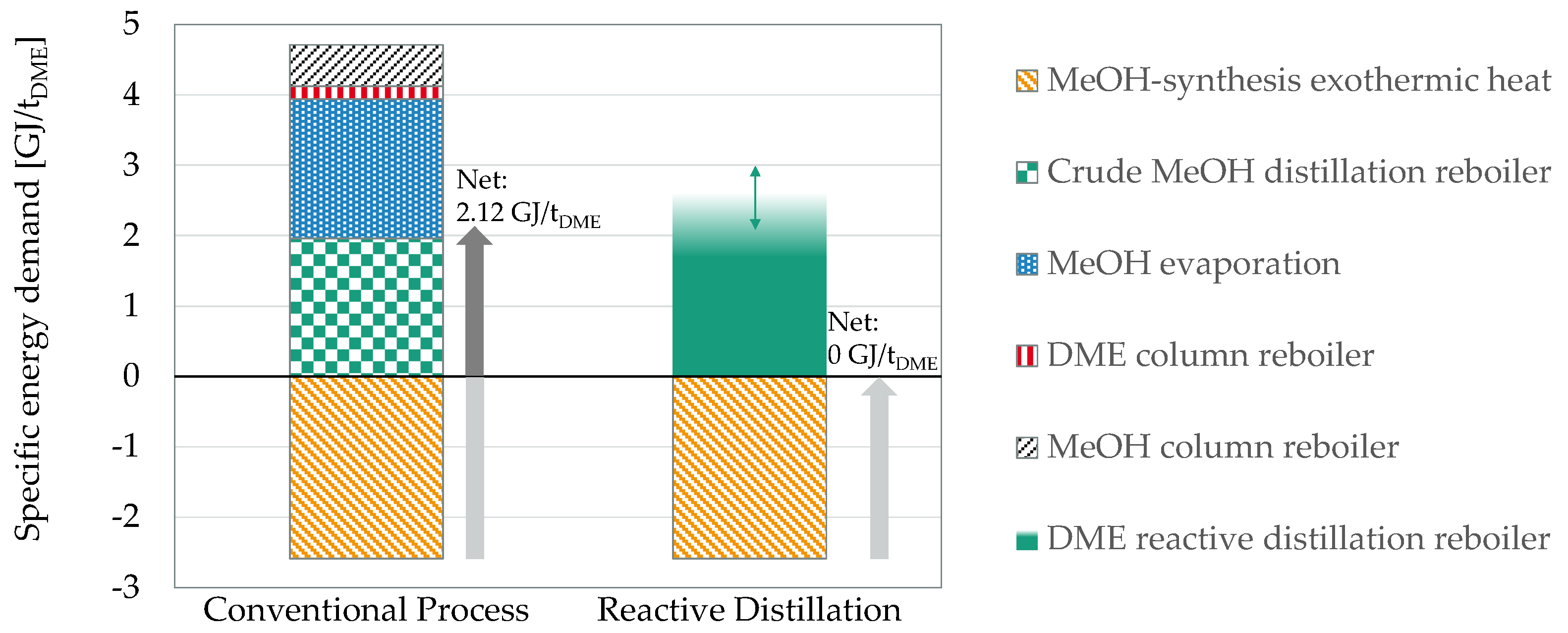
Figure 4 compares the specific energy demand per ton DME of the process intensification approach based on RD with the conventional process. In both process routes, the residual heat from the exothermic MeOH synthesis is accounted for as a negative energy demand. The diagram illustrates that the thermal energy demand for MeOH distillation and evaporation as well as both distillation columns amount to more than 4.7 GJ/t for the conventional DME process. Considering integration of the reaction enthalpy of the MeOH synthesis 2.12 GJ/t is still required to be supplied from external sources. The RD approach, in contrast, allows omission of most of the required energy demands since the respective unit operations are not required for the process. Hence, the RD reboiler remains the only major heat consuming equipment. As mentioned above, the absolute energy demand depends on the complex interplay between catalyst selection and sizing of the column and is adjustable over a wide range. Overall, even a net-zero energy demand process could be realized based on the RD approach.
This comparison illustrates how the presented PI approach comprises multiple intensification techniques, all of which fall within the category of “process-intensifying methods”. Firstly, the shift from gas- to liquid-phase reaction eliminates the necessity of the energy-intensive evaporation of the feed, resulting in energy savings and a process simplification. Besides, the implementation of the RD concept represents a process integration of three unit operations into one multifunctional reactor:
- (a)
- the feedstock purification (crude MeOH distillation),
- (b)
- the DME synthesis reactor and
- (c)
- the product separation.
This exceptionally high degree of intensification is possible since water is the by-product of both the DME synthesis and the methanol synthesis. Hence, both reaction steps benefit from the in situ water removal in the RD approach at the same time. In practice, the integration of the feedstock purification (crude MeOH distillation) represents a major advantage, as this process-step remains the main energy consumer in the conventional process consuming a share of more than 40% of the overall energy demand of DME production starting from crude MeOH. Furthermore, the in situ removal of the product allows the complete conversion of the feedstock and consequently avoids recycle streams including corresponding equipment, which remains common in multifunctional reactors. This achievement is of great importance regarding a self-sufficient operation in remote areas with high PtX potential as explained in the introduction.
Overall, the intensified process shows a lower utilities demand and a significantly simplified process layout compared to the conventional process, and thus illustrates how multiple process-intensifying methods can be combined to yield a better process.
4. Process Intensification for Power-to-OME Processes
4.1. Background
In comparison to NH3 and DME, the current global production capacity of OME is relatively small and is mainly in China. Due to the chemical and physical properties coupled with the non-toxic, environmentally benign, and favorable combustible behavior, OME can be used in a wide range of applications. It was investigated as a selective polymer solvent [64], for CO2 absorption [65], and as a fuel in fuel cells [66,67,68,69,70]. OMEn (chemical formula CH3O(CH2O)nCH3) with the chain length (OME3–5) particularly is intensively investigated for the combustion application as a diesel blend or substitute. This is due to significantly low soot formation upon combustion, while allowing significant reduction of NOx emissions [64,65,66,67,68,69,70,71,72,73,74,75].
OME≥2 () is synthesized in the liquid phase at 50–100 °C in presence of a solid acid catalyst (e.g., IER). Applying MeOH as the methyl capping group supplier and a formaldehyde (FA, chemical formula CH2O) source, OME≥1 () and H2O are formed, following Equation (3). Using methylal (OME1, ) or DME instead of MeOH, no H2O is formed as by-product, as shown in Equation (4). Formalin and para-FA (pFA, chemical formula HO(CH2O)nH with ) can be used as the FA source, but already contains H2O whose presence leads to the formation of several side-products. As an alternative FA source, trioxane (TRI, chemical formula (CH2O)3) or anhydrous FA (FAan) can be applied as water-free FA sources. Thereby, TRI is converted to FA in presence of an acid catalyst following Equation (5) [76,77].
OMEn can be produced following an aqueous route under presence of H2O or an anhydrous route, depending on the choice of feedstock [77]. Typical for the anhydrous route is the synthesis from OME1 and TRI, which exhibits the benefit of a simple product purification due to the absence of H2O within the synthesis product, but requires expensive feedstock [77]. An alternative concept is the aqueous route, which is based on MeOH and concentrated formalin, which is a significantly less expensive feedstock, but requires a complex product purification due to the presence of H2O within the synthesis mixture. The purification of the highly non-ideal and reactive product mixture is cumbersome, due to several azeotropes, complex vapor-liquid-liquid equilibria (VLLE), challenges regarding FA solidification and the separation of H2O from the process. H2O management remains a key hurdle for the realization of a scalable OME3–5 production. Research and development focused in the last decades on various H2O separation strategies, such as extraction [78,79,80,81,82,83,84,85], adsorption [76,86], or membranes [87]. The long-term stability of the materials applied for the previous concepts, as well as the efficiency and the scalability of these approaches are crucial for their application and remain under investigation.
Besides the H2O separation, the synthesis towards OME is less selective for the aqueous route, due to the formation of many side-products which reflects upon the process energy efficiency [88]. H2O is not only formed during the synthesis but enters the process with the FA source formalin. This is a result of the state-of-the-art aqueous FA (FAaq) production processes, which are based on the partial oxidation of MeOH with air (Equation (6)) and dehydrogenation of MeOH (Equation (7)). Silver is used as a catalyst in the BASF process and iron-molybdenum based catalysts are used in the Formox process [89].
4.2. Power-to-OME
OME production is based on MeOH, which can be produced from renewable feedstock such as green H2 and CO2 [54,90]. While a large-scale production of MeOH based on renewable feedstock has already been implemented [91], only a paucity of information remains available regarding OME production plants. In China, OME plants are reported to be in operation or under construction with production capacities of 10–400 kt/a but are mostly based on fossil feedstock. However, no information is available regarding the product quality, reproducibility and long-term production capacities [92,93]. The bottleneck for the technology deployment for OME production remains the implementation and demonstration of a simple, efficient and scalable product purification process.
4.3. Process Intensification Methods
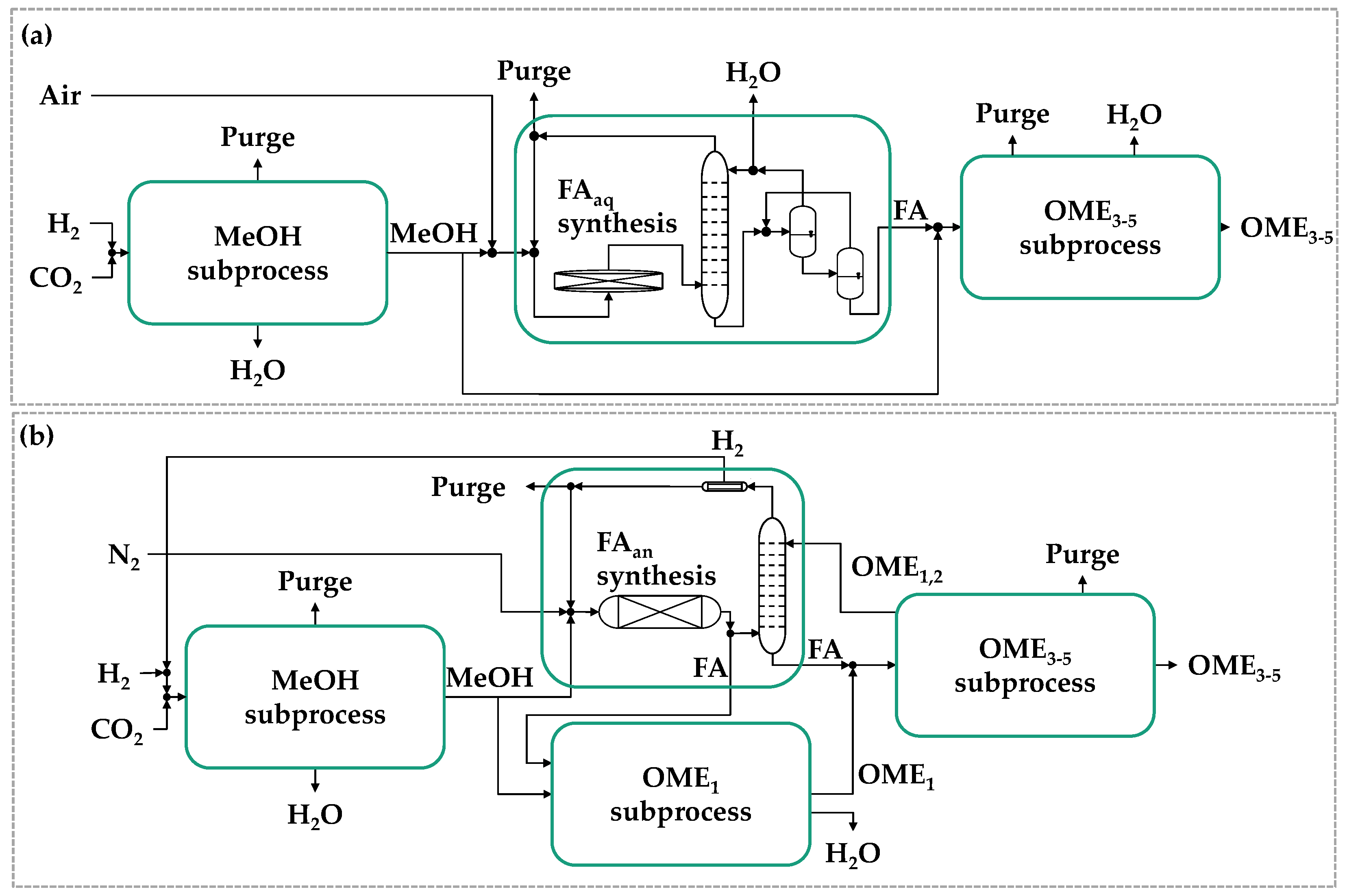
To circumvent the separation of H2O from the process, different process modifications were proposed adopting methyl capping group suppliers (e.g., DME or OME1) and using TRI or pFA as FA sources [92,94,95]. This leads to two main Power-to-OME process concepts based on green H2 and captured CO2 which are depicted in Figure 5. While Figure 5a is based on formalin as FA source, Figure 5b represents the concept using anhydrous FA (FAan) instead. From methanol and FAan OME1 is produced to be reacted further with FAan for higher OME synthesis. Therefore, no H2O is formed within the OME synthesis in this route [90].
While the solid pFA presents a cheaper feedstock than TRI, it still contains about 1–10 wt.% H2O [89], which requires removal from the process. The alternative FAan feedstock can be synthesized via endothermic dehydrogenation of MeOH at temperatures > 650 °C following Equation (7) and avoids H2O formation, while H2 is formed as valuable side product [96,97,98]. The implementation of the FAan synthesis into the OME process chain starting from the production of MeOH (Figure 5b) contains two main benefits. Firstly, the provision of FA without any additional H2O and without the energy intensive production of TRI, as discussed above. The second benefit addresses the potential for reutilizing the valuable side product H2. Downstream to the separation of FAan from the gaseous product stream, H2 can be separated and used for the production of MeOH, as seen in (Figure 5b). Therefore, instead of oxidizing this valuable H2 to H2O following the state-of-the-art FAaq synthesis (Equation (6)), the reutilization of H2 following the FAan synthesis (Equation (7)) lowers the amount of H2 required to produce the target end product OME3–5. This reflects significantly on the operational costs, especially considering the context of PtX processes using green H2 [90].
The FAan synthesis was investigated and experimentally tested over a broad range of catalyst materials by several research groups, but was not yet demonstrated in long-term experiments or in an industrially relevant environment [96,97,98]. Besides the catalyst stability as a key challenge to realize the FAan synthesis, a suitable reactor design considering the endothermic reaction at a high temperature and the strongly reducing H2 environment remains challenging.
Moreover, a complete conversion of MeOH is required and a high selectivity to FA is desired to circumvent the H2O separation management for the OME product purification. Sauer et al., [97] achieved a complete conversion of MeOH with a selectivity to FA of 70% and the formation of CO as a side product using an electrically heated tube wall reactor with a catalyst coated inner wall. High MeOH conversion and FA selectivity require challenging reaction conditions: For high selectivity, in particular, very short residence times in the heated reaction zone and on the catalyst surface, as well as rapid quenching of the product stream to 100–150 °C is required to avoid dissociation reactions towards CO. The temperature should not fall below 100 °C to avoid potential solidification of gaseous monomeric FA [97]. Ouda et al., [98] developed an electrically heated annular counter current reactor (ACCR) for the FAan synthesis achieving a rather high FA selectivity of 90% at low MeOH conversions of 40%.
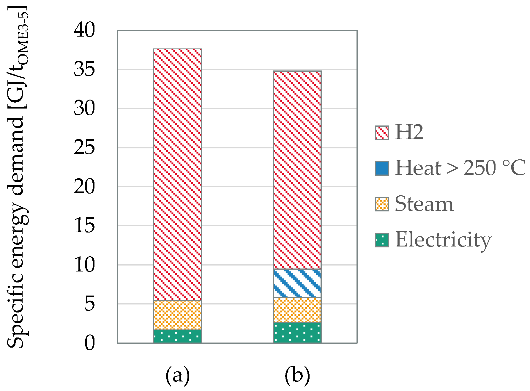
The potential of the choice of the FA source - being either concentrated formalin or FAan - is compared with respect to the specific energy demand, the carbon footprint and the specific wastewater formation based on the results of Mantei et al. [90]. Figure 6 compares the specific energy demand per ton OME3–5 produced depending on the FA source, achieved after heat integration between all subprocesses. The overall energy demand is distinguished in electricity, steam and heat (above 250 °C), while the H2 required in the processes is also accounted for as an energy demand based on the lower heating value. The process based on concentrated formalin requires less electricity, steam and heat than its counterpart based on FAan. The FAan based process, in contrast, requires high amounts of heat, due to the endothermic reaction at >650 °C. However, FAan exhibits a slightly lower overall energy demand, due to 20% less H2 required as a feedstock. Hence, both processes are rather comparable exhibiting energetic efficiencies in the order of 50–54%.
Besides the energy demand, the reduction of greenhouse gas emissions represents an important motivation for implementing PI approaches [13]. In terms of carbon footprint the OME3–5 production using FAan clearly outperforms the formalin-based process, since the heat required for the endothermic reaction is provided directly via renewable electricity [90]. Comparing the specific amount of wastewater produced for the production of OME3–5 the FAan based process (1 kg/kg) outperforms its counterpart using formalin (1.3 kg/kg), as well. Furthermore, the wastewater produced in the formalin route still contains about 10–15 wt.% of FA, which complicates its treatment. Therefore, the OME3–5 production via FAan combines a slightly higher energetic efficiency with a more sustainable production of OME3–5, which remains within the confines of the main goals of PI methods in the PtX context.
With innovation and developments towards electrically driven selective FAan synthesis reactor, the intensified process shows a significant potential towards simpler, compacter, more energy efficient, and importantly a low carbon footprint overall OME value chain.
5. Summary and Conclusions
In this work, the potential of PI methods for the development of efficient, competitive, compact and low-maintenance thermochemical processes was identified and discussed supported by examples for the three PtX-products namely: NH3, DME and OME. A brief description of the-state-of-the-art processes and PI approaches was provided. In the case of NH3, advanced ruthenium catalysts allowed lower operating temperatures, thus paving the way for adsorption as a new separation technology, which can be integrated into a multifunctional reactor with in situ removal of NH3. Consequently, the specific energy demand for the integrated reactor presented as per ton of NH3 could be almost halved in comparison to the conventional Haber–Bosch process. In the case of DME synthesis, ion exchange resin catalysts allow a reduction of the reaction temperature below the boiling temperature of methanol, thus allowing the shift from gas- to liquid-phase synthesis, which in turn enables the implementation of an RD process. A quasi-net-zero energy demand process could be achieved in a single unit operation replacing three unit operations when the integration between MeOH synthesis and DME–RD is properly realized. For PI of the OME synthesis process, the FAan synthesis based on methanol dehydrogenation in electrically heated reactors was implemented instead of the state-of-the-art FAaq synthesis. Furthermore, OME1 was used as a methyl capping group supplier in place of MeOH which together circumvents the challenge of the cumbersome H2O separation within the conventional OME production process. Another benefit observed was the separation and recycling of the valuable by-product H2 of the FAan synthesis. This approach led to 20% less H2 feedstock required per ton of OME3–5 in comparison to the conventional aqueous process. Additionally, approximately 23% less wastewater was produced based on the FAan synthesis.
Considering the described challenges of PtX processes, the PI measures presented offer several promising solutions. Primarily, process integration measures allow for significantly simplified processes, consequently leading to reduced component numbers and reduced maintenance efforts. Moreover, the potential elimination of recycle loops due to equilibrium shift of the reaction towards products reduces the complex interactions in a dynamic operation. Besides, simpler and smaller recycle loops can reduce maintenance efforts of the circulating equipment i.e., compressors. Additionally, the PI methods offer the potential to reduce the energy demand of the previously discussed processes against the conventional ones. All the PI approaches extended and discussed are research endeavors which remain under development in our work group illustrating the relevance of PI approaches in PtX processes.
Author Contributions
Introduction, Summary and Power-to-Ammonia, T.C.; Power-to-DME, M.S.; Power-to-OME, F.M.; writing—review and editing, O.S. and R.G.; scientific supervision, O.S.; project administration, O.S. All authors have read and agreed to the published version of the manuscript.
Funding
This research received no external funding.
Institutional Review Board Statement
Not applicable.
Informed Consent Statement
Not applicable.
Data Availability Statement
Analyzed data available in the original sources. See citations.
Acknowledgments
Deutsche Bundesstiftung Umwelt (DBU) is gratefully acknowledged for funding of the work of Thomas Cholewa (20020/671), Franz Mantei (20018/541) and Malte Semmel (20020/662).
Conflicts of Interest
The authors declare no conflict of interest.
References
- IPCC, 2. Summary for Policymakers. In Climate Change 2021: The Physical Science Basis. Contribution of Working Group I to the Sixth Assessment Report of the Intergovernmental Panel on Climate Change: The Physical Science Basis; Cambridge University Press: Cambridge, UK, 2021; in press. [Google Scholar]
- Rogelj, J.; Shindell, D.; Jiang, K.; Fifita, S.; Forster, P.; Ginzburg, V.; Handa, C.; Kheshgi, H.; Kobayashi, S.; Kriegler, E.; et al. Mitigation pathways compatible with 1.5 °C in the context of sustainable development. In Global Warming of 1.5 °C; Intergovernmental Panel on Climate Change: Geneva, Switzerland, 2018; pp. 93–174. [Google Scholar]
- International Renewable Energy Agency. Green Hydrogen: A Guide to Policy Making. 2020. Available online: https://www.irena.org/-/media/Files/IRENA/Agency/Publication/2020/Nov/IRENA_Green_hydrogen_policy_2020.pdf (accessed on 8 December 2021).
- Hank, C.; Sternberg, A.; Köppel, N.; Holst, M.; Smolinka, T.; Schaadt, A.; Hebling, C.; Henning, H.-M. Energy efficiency and economic assessment of imported energy carriers based on renewable electricity. Sustain. Energy Fuels 2020, 4, 2256–2273. [Google Scholar] [CrossRef]
- International Energy Agency. World Energy Outlook 2020, Outlook for Energy Demand. Available online: https://www.iea.org/reports/world-energy-outlook-2020/outlook-for-energy-demand (accessed on 3 August 2021).
- Sterchele, P.; Brandes, J.; Heilig, J.; Wrede, D.; Kost, C.; Schlegl, T.; Bett, A.; Henning, H.-M. Wege zu Einem Klimaneutralen Energiesystem: Die Deutsche Energiewende im Kontext Gesellschaftlicher Verhaltensweisen 2020; Fraunhofer-Institut für Solare Energiesysteme ISE: Freiburg im Breisgau, Germany, 2020. [Google Scholar]
- Nanba, T. Hydrogen Storage and Utilization by Using Carrier Compounds for effective usage of renewable energy. In Proceedings of the World Hydrogen Technologies Convention, Tokyo, Japan, 3 June 2019. [Google Scholar]
- Nazir, H.; Muthuswamy, N.; Louis, C.; Jose, S.; Prakash, J.; Buan, M.E.; Flox, C.; Chavan, S.; Shi, X.; Kauranen, P.; et al. Is the H2 economy realizable in the foreseeable future? Part II: H2 storage, transportation, and distribution. Int. J. Hydrog. Energy 2020, 45, 20693–20708. [Google Scholar] [CrossRef]
- Schemme, S.; Breuer, J.L.; Köller, M.; Meschede, S.; Walman, F.; Samsun, R.C.; Peters, R.; Stolten, D. H2-based synthetic fuels: A techno-economic comparison of alcohol, ether and hydrocarbon production. Int. J. Hydrog. Energy 2020, 45, 5395–5414. [Google Scholar] [CrossRef]
- Jenck, J.F.; Agterberg, F.; Droescher, M. Products and processes for a sustainable chemical industry: A review of achievements and prospects. Green Chem. 2004, 6, 544–556. [Google Scholar] [CrossRef]
- Stankiewicz, A.I.; Moulijn, J.A. Process intensification: Transforming chemical engineering. Chem. Eng. Prog. 2000, 96, 22–34. [Google Scholar]
- Ramshaw, C. Process Intensification and Green Chemistry. Green Chem. 1999, 1, G15–G17. [Google Scholar] [CrossRef]
- Gallucci, F.; van Sint Annaland, M. (Eds.) Process Intensification for Sustainable Energy Conversion; Wiley: Chichester, UK, 2015; ISBN 978-1-118-44935-6. [Google Scholar]
- Hüther, A.; Geißelmann, A.; Hahn, H. Prozessintensivierung—Eine strategische Option für die chemische Industrie. Chem. Ing. Tech. 2005, 77, 1829–1837. [Google Scholar] [CrossRef]
- Sitter, S.; Chen, Q.; Grossmann, I.E. An overview of process intensification methods. Curr. Opin. Chem. Eng. 2019, 25, 87–94. [Google Scholar] [CrossRef]
- Agar, D.W.; Ruppel, W. Multifunktionale Reaktoren für die heterogene Katalyse. Chem. Ing. Tech. 1988, 60, 731–741. [Google Scholar] [CrossRef]
- Bundesministerium für Wirtschaft und Energie (BMWi) (2020): Die Nationale Wasserstoffstrategie. Hg. v. Bundesministerium für Wirtschaft und Energie (BMWi). Berlin. Available online: https://www.bmwi.de/Redaktion/DE/Publikationen/Energie/die-nationale-wasserstoffstrategie.html (accessed on 8 December 2021).
- Yasmina, B.; Andras, P.; Anish, P.; van Chritian, E.S. Power to Ammonia: Rethinking the Role of Ammonia—From a Value Product to a Flexible Energy Carrier (FlexNH3); Hanzehogeschool Groningen: Groningen, The Netherlands, 2016; p. 100. [Google Scholar]
- Appl, M. Ammonia: 2. Production Processes. In Ullmann’s Encyclopedia of Industrial Chemistry; Wiley-VCH, Ed.; Wiley-VCH Verlag GmbH & Co. KGaA: Weinheim, Germany, 2012; ISBN 9783527306732. [Google Scholar]
- Nayak-Luke, R.; Bañares-Alcántara, R.; Wilkinson, I. “Green” Ammonia: Impact of Renewable Energy Intermittency on Plant Sizing and Levelized Cost of Ammonia. Ind. Eng. Chem. Res. 2018, 57, 14607–14616. [Google Scholar] [CrossRef] [Green Version]
- Afif, A.; Radenahmad, N.; Cheok, Q.; Shams, S.; Kim, J.H.; Azad, A.K. Ammonia-fed fuel cells: A comprehensive review. Renew. Sustain. Energy Rev. 2016, 60, 822–835. [Google Scholar] [CrossRef]
- Klüssmann, J.; Ekknund, L.; Ivarsson, A.; Schramm, J. Ammonia Application in IC Engines. 2020. Available online: https://iea-amf.org/app/webroot/files/file/other%20publications/Ammonia%20Application%20in%20IC%20Engines.pdf (accessed on 8 December 2021).
- Christensen, C.H.; Johannessen, T.; Sørensen, R.Z.; Nørskov, J.K. Towards an ammonia-mediated hydrogen economy? Catal. Today 2006, 111, 140–144. [Google Scholar] [CrossRef]
- Brown, T. Ammonia Production Causes 1% of Total Global GHG Emissions. Available online: https://ammoniaindustry.com/ammonia-production-causes-1-percent-of-total-global-ghg-emissions/ (accessed on 19 November 2019).
- Schlögl, R. Katalytische Ammoniaksynthese—Eine “unendliche Geschichte”? Angew. Chem. 2003, 115, 2050–2055. [Google Scholar] [CrossRef]
- Twigg, M.V.; Spencer, M.S.; Jennings, J.R. Catalytic Ammonia Synthesis; Springer: Boston, MA, USA, 1991; ISBN 978-1-4757-9594-3. [Google Scholar]
- Liu, H. Ammonia synthesis catalyst 100 years: Practice, enlightenment and challenge. Chin. J. Catal. 2014, 35, 1619–1640. [Google Scholar] [CrossRef]
- Schlögl, R. Catalytic Synthesis of Ammonia—A “Never-Ending Story”? Angew. Chem. Int. Ed. 2003, 42, 2004–2008. [Google Scholar] [CrossRef]
- Fujimura, Y.; Kai, M.; Fujimoto, T.; Fujimoto, S.; Atsumi, R.; Nishi, M.; Mochizuki, T.; Nanba, T. Demonstration and optimization of Green Ammonia Production Operation Responding to Fluctuating Hydrogen Production from Renewable Energy. In Proceedings of the AIChE Annual Meeting, Orlando, FL, USA, 10–15 November 2019. [Google Scholar]
- Ayvalı, T.; Tsang, S.C.E.; Van Vrijaldenhoven, T. The Position of Ammonia in Decarbonising Maritime Industry: An Overview and Perspectives: Part I: Technological advantages and the momentum towards ammonia-propelled shipping. Johns. Matthey Technol. Rev. 2021, 65, 275–290. [Google Scholar] [CrossRef]
- Rouwenhorst, K.H.R.; Krzywda, P.M.; Benes, N.E.; Mul, G.; Lefferts, L. Ammonia, 4. Green Ammonia Production. In Ullmann’s Encyclopedia of Industrial Chemistry; Wiley-VCH, Ed.; Wiley-VCH Verlag GmbH & Co. KGaA: Weinheim, Germany, 2012; pp. 1–20. ISBN 9783527306732. [Google Scholar]
- Aika, K.; Hori, H.; Ozaki, A. Activation of nitrogen by alkali metal promoted transition metal I. Ammonia synthesis over ruthenium promoted by alkali metal. J. Catal. 1972, 27, 424–431. [Google Scholar] [CrossRef]
- Nishi, M.; Chen, S.-Y.; Takagi, H. A Mesoporous Carbon-Supported and Cs-promoted Ru Catalyst with Enhanced Activity and Stability for Sustainable Ammonia Synthesis. ChemCatChem 2018, 10, 3411–3414. [Google Scholar] [CrossRef]
- Nishi, M.; Chen, S.-Y.; Takagi, H. Mild Ammonia Synthesis over Ba-Promoted Ru/MPC Catalysts: Effects of the Ba/Ru Ratio and the Mesoporous Structure. Catalysts 2019, 9, 480. [Google Scholar] [CrossRef] [Green Version]
- Javaid, R.; Matsumoto, H.; Nanba, T. Influence of Reaction Conditions and Promoting Role of Ammonia Produced at Higher Temperature Conditions in Its Synthesis Process over Cs-Ru/MgO Catalyst. ChemistrySelect 2019, 4, 2218–2224. [Google Scholar] [CrossRef]
- Rouwenhorst, K.; Krzywda, P.M.; Benes, N.E.; Mul, G.; Lefferts, L. Ammonia Production Technologies. In Techno-Economic Challenges of Green Ammonia as an Energy Vector; Elsevier: Amsterdam, The Netherlands, 2021; pp. 41–83. ISBN 9780128205600. [Google Scholar]
- Liu, H. Ammonia Synthesis Catalysts: Innovation and Practice. World Scientific Pub. Co: Singapore; Hackensack, NJ, USA; Beijing, China, 2013; ISBN 978-981-4355-77-3. [Google Scholar]
- Nikačević, N.; Jovanović, M.; Petkovska, M. Enhanced ammonia synthesis in multifunctional reactor with in situ adsorption. Chem. Eng. Res. Des. 2011, 89, 398–404. [Google Scholar] [CrossRef]
- Liu, C.Y.; Aika, K.-I. Ammonia Adsorption on Ion Exchanged Y-zeolites as Ammonia Storage Material. J. Jpn. Pet. Inst. 2003, 46, 301–307. [Google Scholar] [CrossRef]
- Matito-Martos, I.; García-Reyes, J.; Martin-Calvo, A.; Dubbeldam, D.; Calero, S. Improving Ammonia Production Using Zeolites. J. Phys. Chem. 2019, 123, 18475–18481. [Google Scholar] [CrossRef]
- Smith, C.; Torrente-Murciano, L. Exceeding Single-Pass Equilibrium with Integrated Absorption Separation for Ammonia Synthesis Using Renewable Energy—Redefining the Haber-Bosch Loop. Adv. Energy Mater. 2021, 11, 2003845. [Google Scholar] [CrossRef]
- Smith, C.; McCormick, A.V.; Cussler, E.L. Optimizing the Conditions for Ammonia Production Using Absorption. ACS Sustain. Chem. Eng. 2019, 7, 4019–4029. [Google Scholar] [CrossRef]
- Malmali, M.; Wei, Y.; McCormick, A.; Cussler, E.L. Ammonia Synthesis at Reduced Pressure via Reactive Separation. Ind. Eng. Chem. Res. 2016, 55, 8922–8932. [Google Scholar] [CrossRef]
- Malmali, M.; Le, G.; Hendrickson, J.; Prince, J.; McCormick, A.V.; Cussler, E.L. Better Absorbents for Ammonia Separation. ACS Sustain. Chem. Eng. 2018, 6, 6536–6546. [Google Scholar] [CrossRef]
- Liu, C.Y.; Aika, K.-I. Ammonia Absorption into Alkaline Earth Metal Halide Mixtures as an Ammonia Storage Material. Ind. Eng. Chem. Res. 2004, 43, 7484–7491. [Google Scholar] [CrossRef]
- Klerke, A.; Christensen, C.H.; Nørskov, J.K.; Vegge, T. Ammonia for hydrogen storage: Challenges and opportunities. J. Mater. Chem. 2008, 18, 2304–2310. [Google Scholar] [CrossRef]
- Cussler, E.; McCormick, A.; Reese, M.; Malmali, M. Ammonia Synthesis at Low Pressure. J. Vis. Exp. 2017, 112, e55691. [Google Scholar] [CrossRef]
- Christensen, C.H.; Sørensen, R.Z.; Johannessen, T.; Quaade, U.J.; Honkala, K.; Elmøe, T.D.; Køhler, R.; Nørskov, J.K. Metal ammine complexes for hydrogen storage. J. Mater. Chem. 2005, 15, 4106–4108. [Google Scholar] [CrossRef]
- Smith, C.; Hill, A.K.; Torrente-Murciano, L. Current and future role of Haber–Bosch ammonia in a carbon-free energy landscape. Energy Environ. Sci. 2020, 13, 331–344. [Google Scholar] [CrossRef]
- Liu, H.; Han, W.; Huo, C.; Cen, Y. Development and application of wüstite-based ammonia synthesis catalysts. Catal. Today 2019, 355, 110–127. [Google Scholar] [CrossRef]
- Palys, M.J.; McCormick, A.; Cussler, E.L.; Daoutidis, P. Modeling and Optimal Design of Absorbent Enhanced Ammonia Synthesis. Processes 2018, 6, 91. [Google Scholar] [CrossRef] [Green Version]
- Fleisch, T.; Basu, A.; Sills, R. Introduction and advancement of a new clean global fuel: The status of DME developments in China and beyond. J. Nat. Gas Sci. Eng. 2012, 9, 94–107. [Google Scholar] [CrossRef]
- Semmel, M.; Ali, R.E.; Ouda, M.; Schaadt, A.; Sauer, J.; Hebling, C. Power-to-DME: A cornerstone towards a sustainable energy system. In Power to Fuel: How to Speed Up a Hydrogen Economy; Spazzafumo, G., Ed.; Elsevier: Amsterdam, The Netherlands, 2021; pp. 123–151. ISBN 9780128228135. [Google Scholar]
- Nestler, F.; Krüger, M.; Full, J.; Hadrich, M.J.; White, R.J.; Schaadt, A. Methanol Synthesis—Industrial Challenges within a Changing Raw Material Landscape. Chem. Ing. Tech. 2018, 90, 1409–1418. [Google Scholar] [CrossRef]
- Pontzen, F.; Liebner, W.; Gronemann, V.; Rothaemel, M.; Ahlers, B. CO2-based methanol and DME—Efficient technologies for industrial scale production. Catal. Today 2011, 171, 242–250. [Google Scholar] [CrossRef]
- Azizi, Z.; Rezaeimanesh, M.; Tohidian, T.; Rahimpour, M.R. Dimethyl ether: A review of technologies and production challenges. Chem. Eng. Process. Process Intensif. 2014, 82, 150–172. [Google Scholar] [CrossRef]
- Van Kampen, J.; Boon, J.; van Berkel, F.; Vente, J.; Annaland, M.V.S. Steam separation enhanced reactions: Review and outlook. Chem. Eng. J. 2019, 374, 1286–1303. [Google Scholar] [CrossRef]
- Van Kampen, J.; Boon, J.; Vente, J.; Annaland, M.V.S. Sorption enhanced dimethyl ether synthesis for high efficiency carbon conversion: Modelling and cycle design. J. CO2 Util. 2020, 37, 295–308. [Google Scholar] [CrossRef]
- Diban, N.; Urtiaga, A.M.; Ortiz, I.; Ereña, J.; Bilbao, J.; Aguayo, A.T. Influence of the membrane properties on the catalytic production of dimethyl ether with in situ water removal for the successful capture of co2. Chem. Eng. J. 2013, 234, 140–148. [Google Scholar] [CrossRef]
- Diban, N.; Aguayo, A.T.; Bilbao, J.; Urtiaga, A.; Ortiz, I. Membrane Reactors for in Situ Water Removal: A Review of Applications. Ind. Eng. Chem. Res. 2013, 52, 10342–10354. [Google Scholar] [CrossRef]
- Bîldea, C.S.; Győrgy, R.; Brunchi, C.C.; Kiss, A.A. Optimal design of intensified processes for DME synthesis. Comput. Chem. Eng. 2017, 105, 142–151. [Google Scholar] [CrossRef] [Green Version]
- Lei, Z.; Zou, Z.; Dai, C.; Li, Q.; Chen, B. Synthesis of dimethyl ether (DME) by catalytic distillation. Chem. Eng. Sci. 2011, 66, 3195–3203. [Google Scholar] [CrossRef]
- An, W.; Chuang, K.T.; Sanger, A.R. Dehydration of Methanol to Dimethyl Ether by Catalytic Distillation. Can. J. Chem. Eng. 2008, 82, 948–955. [Google Scholar] [CrossRef]
- Zhenova, A.; Pellis, A.; Milescu, R.A.; McElroy, C.R.; White, R.J.; Clark, J.H. Solvent Applications of Short-Chain Oxymethylene Dimethyl Ether Oligomers. ACS Sustain. Chem. Eng. 2019, 7, 14834–14840. [Google Scholar] [CrossRef]
- Schappals, M.; Breug-Nissen, T.; Langenbach, K.; Burger, J.; Hasse, H. Solubility of Carbon Dioxide in Poly (oxymethylene) Dimethyl Ethers. J. Chem. Eng. Data 2017, 62, 4027–4031. [Google Scholar] [CrossRef]
- Vigier, F.; Coutanceau, C.; Léger, J.; Dubois, J. Polyoxymethylenedimethylether (CH3O(CH2O)nCH3) oxidation on Pt and Pt/Ru supported catalysts. J. Power Sources 2008, 175, 82–90. [Google Scholar] [CrossRef]
- Devaux, D.; Yano, H.; Uchida, H.; Dubois, J.-L.; Watanabe, M. Electro-oxidation of hydrolysed poly-oxymethylene-dimethylether on PtRu supported catalysts. Electrochim. Acta 2011, 56, 1460–1465. [Google Scholar] [CrossRef]
- Baranton, S.; Uchida, H.; Tryk, D.A.; Dubois, J.L.; Watanabe, M. Hydrolyzed polyoxymethylenedimethylethers as liquid fuels for direct oxidation fuel cells. Electrochim. Acta 2013, 108, 350–355. [Google Scholar] [CrossRef]
- Kakinuma, K.; Kim, I.-T.; Senoo, Y.; Yano, H.; Watanabe, M.; Uchida, M. Electrochemical Oxidation of Hydrolyzed Poly Oxymethylene-dimethyl Ether by PtRu Catalysts on Nb-Doped SnO2−δ Supports for Direct Oxidation Fuel Cells. ACS Appl. Mater. Interfaces 2014, 6, 22138–22145. [Google Scholar] [CrossRef] [PubMed]
- Sakaida, S.; Sugiyama, M.; Nagayama, R.; Tanaka, K.; Konno, M. Potential of hydrolyzed oxymethylene dimethyl ether for the suppression of fuel crossover in polymer electrolyte fuel cells. Int. J. Hydrog. Energy 2021, 46, 10892–10902. [Google Scholar] [CrossRef]
- Wolfgang, M.; Jacob, E.; Härtl, M.; Wachtmeister, G. (Eds.) Synthetic Fuels—OME 1: A Potentially Sustainable. In Proceedings of the Wiener Motorensymposium, Vienna, Austria, 8–9 May 2014. Diesel Fuel. [Google Scholar]
- Härtl, M.; Gaukel, K.; Pélerin, D.; Wachtmeister, G. Oxymethylene Ether as Potentially CO2-neutral Fuel for Clean Diesel Engines Part 1: Engine Testing. MTZ Worldw. 2017, 78, 52–59. [Google Scholar] [CrossRef]
- Jacob, E.; Maus, W. Oxymethylene Ether as Potentially Carbon-neutral Fuel for Clean Diesel Engines Part 2: Compliance with the Sustainability Requirement. MTZ Worldw. 2017, 78, 52–57. [Google Scholar] [CrossRef]
- Münz, M.; Mokros, A.; Töpfer, D.; Beidl, C. OME—Assessment of Particle Emissions in Real Driving Conditions. MTZ Worldw. 2018, 79, 16–21. [Google Scholar] [CrossRef]
- Lumpp, B.; Rothe, D.; Pastötter, C.; Lämmermann, R.; Jacob, E. Oxymethylene Ethers as Diesel Fuel Additives of the Future. Mtz Worldw. 2011, 72, 34–38. [Google Scholar] [CrossRef]
- Schmitz, N.; Ströfer, E.; Burger, J.; Hasse, H. Conceptual Design of a Novel Process for the Production of Poly (oxymethylene) Dimethyl Ethers from Formaldehyde and Methanol. Ind. Eng. Chem. Res. 2017, 56, 11519–11530. [Google Scholar] [CrossRef]
- Burger, J. A novel process for the production of diesel fuel additives by hierarchical design. Ph.D. Thesis, University of Kaiserslautern, Kaiserslautern, Germany, 2012. [Google Scholar]
- Li, X.; Cao, J.; Nawaz, M.A.; Hu, Y.; Liu, D. Experimental and Correlated Liquid–Liquid Equilibrium Data for Ternary Systems (Water + Poly (oxymethylene) Dimethyl Ethers + Toluene) at T = 293.15 and 303.15 K and p = 101.3 kPa. J. Chem. Eng. Data 2019, 64, 5548–5557. [Google Scholar] [CrossRef]
- Li, X.; Tian, H.; Zhang, W.; Liu, D. Production Process for Diesel Fuel Components Polyoxymethylene Dimethyl Ethers from Methanol and Formaldehyde Solution. Int. J. Chem. Mol. Eng. 2018, 12, 536–541. [Google Scholar] [CrossRef]
- Wang, L.; Zhou, S.; Li, P.; Li, P.; Li, Q.; Yu, Y. Measurement and Thermodynamic Models for Ternary Liquid–Liquid Equilibrium Systems {Water + Polyoxymethylene Dimethyl Ethers + 4-Methyl-2-pentanol} at Different Temperatures. J. Chem. Eng. Data 2018, 63, 3074–3082. [Google Scholar] [CrossRef]
- Shi, M.; Yu, X.; He, G.; Li, Q. Liquid–Liquid equilibrium for the ternary systems water + DMM3 + (p-xylene, toluene, and n-heptane) at different temperatures. Can. J. Chem. Eng. 2017, 96, 968–977. [Google Scholar] [CrossRef]
- Shi, M.; He, G.; Gan, F.; Yu, X.; Li, Q. Extraction of Low Concentration Aqueous Solution of Methylal: Liquid–Liquid Equilibrium in Water + Methylal + (Cyclohexane and n-Heptane) Ternary Systems. J. Chem. Eng. Data 2017, 62, 2183–2190. [Google Scholar] [CrossRef]
- Zhuang, Z.; Zhang, J.; Liu, D. Liquid-Liquid equilibria for ternary systems polyoxymethylene dimethyl ethers + water + n-hexane. CIESC J. 2016, 67, 3545–3551. [Google Scholar] [CrossRef]
- Zhuang, Z.; Zhang, J.; Liu, X.; Liu, D. Liquid–Liquid equilibria for ternary systems polyoxymethylene dimethyl ethers + para-xylene + water. J. Chem. Thermodyn. 2016, 101, 190–198. [Google Scholar] [CrossRef] [Green Version]
- Oestreich, D.; Lautenschütz, L.; Arnold, U.; Sauer, J. Production of oxymethylene dimethyl ether (OME)-hydrocarbon fuel blends in a one-step synthesis/extraction procedure. Fuel 2018, 214, 39–44. [Google Scholar] [CrossRef]
- Ferre, A.; Burger, J. Coadsorption Equilibria on Molecular Sieves 3A and Densities of Liquid Mixtures Containing Formaldehyde, Methanol, and Water at 295.15 and 313.15 K. Ind. Eng. Chem. Res. 2021, 60, 15256–15263. [Google Scholar] [CrossRef]
- Schmitz, N.; Breitkreuz, C.F.; Ströfer, E.; Burger, J.; Hasse, H. Separation of water from mixtures containing formaldehyde, water, methanol, methylal, and poly(oxymethylene) dimethyl ethers by pervaporation. J. Membr. Sci. 2018, 564, 806–812. [Google Scholar] [CrossRef]
- Held, M.; Tönges, Y.; Pélerin, D.; Härtl, M.; Wachtmeister, G.; Burger, J. On the energetic efficiency of producing polyoxymethylene dimethyl ethers from CO2 using electrical energy. Energy Environ. Sci. 2019, 12, 1019–1034. [Google Scholar] [CrossRef]
- Ullmann’s Encyclopedia of Industrial Chemistry: Formaldehyde; Franz, A.W.; Kronemayer, H.; Pfeiffer, D.; Pilz, R.D.; Reuss, G.; Disteldorf, W.; Gamer, A.O.; Hilt, A. (Eds.) Wiley-VCH Verlag GmbH & Co. KG: Weinheim, Germany, 2016. [Google Scholar]
- Mantei, F.; Ali, R.E.; Baensch, C.; Voelker, S.; Haltenort, P.; Burger, J.; Dietrich, R.-U.; von der Assen, N.; Schaadt, A.; Sauer, J.; et al. Techno-economic assessment and carbon footprint of processes for the large-scale production of oxymethylene dimethyl ethers from carbon dioxide and hydrogen. Sustain. Energy Fuels 2021, 6, 528–549. [Google Scholar] [CrossRef]
- FReSMe Project—From Residual Steel Gases to Methanol. Available online: https://www.carbonrecycling.is/news-media/fresme-project-reaches-final-milestone-from-blast-furnace-waste-emissions-to-ferry-fuel (accessed on 8 December 2021).
- Hackbarth, K.; Haltenort, P.; Arnold, U.; Sauer, J. Recent Progress in the Production, Application and Evaluation of Oxymethylene Ethers. Chem. Ing. Tech. 2018, 90, 1520–1528. [Google Scholar] [CrossRef]
- Dolton Jiangsu Dolton Chemical Technology Co., Ltd. DMMn Plant. Available online: https://www.aldehydeepc.com/dmmn-plant-15609099648755723.html (accessed on 8 December 2021).
- Breitkreuz, C.F.; Schmitz, N.; Ströfer, E.; Burger, J.; Hasse, H. Design of a Production Process for Poly (oxymethylene) Dimethyl Ethers from Dimethyl Ether and Trioxane. Chem. Ing. Tech. 2018, 90, 1489–1496. [Google Scholar] [CrossRef]
- Haltenort, P.; Hackbarth, K.; Oestreich, D.; Lautenschütz, L.; Arnold, U.; Sauer, J. Heterogeneously catalyzed synthesis of oxymethylene dimethyl ethers (OME) from dimethyl ether and trioxane. Catal. Commun. 2018, 109, 80–84. [Google Scholar] [CrossRef]
- Su, S.; Zaza, D.-C.-I.P.; Renken, A. Catalytic dehydrogenation of methanol to water-free formaldehyde. Chem. Eng. Technol. 1994, 17, 34–40. [Google Scholar] [CrossRef]
- Sauer, I.J.; Emig, G. The catalyzed dehydrogenation of methanol to formaldehyde at high temperatures: New insights by modelling of transport phenomena and reaction. Chem. Eng. Technol. 1995, 18, 284–291. [Google Scholar] [CrossRef]
- Ouda, M.; Mantei, F.; Hesterwerth, K.; Eleonora Bargiacchi, E.; Klein, H.; White, R.J. A hybrid description and evaluation of oxymethylene dimethyl ethers synthesis based on the endothermic dehydrogenation of methanol. React. Chem. Eng. 2018, 3, 676–695. [Google Scholar] [CrossRef]
Figure 1.
Simplified process diagram for the conventional Haber–Bosch process (a) and an integrated reactor concept with in situ removal of NH3 in a sorptive process (b).
Figure 1.
Simplified process diagram for the conventional Haber–Bosch process (a) and an integrated reactor concept with in situ removal of NH3 in a sorptive process (b).

Figure 2.
Comparison of specific energy demand per ton liquid NH3 of the conventional synthesis process with novel low-pressure concepts using different separation strategies.
Figure 2.
Comparison of specific energy demand per ton liquid NH3 of the conventional synthesis process with novel low-pressure concepts using different separation strategies.

Figure 3.
Simplified process flowsheet for the conventional DME production process (a) and the PI approach by reactive distillation (b).
Figure 3.
Simplified process flowsheet for the conventional DME production process (a) and the PI approach by reactive distillation (b).

Figure 4.
Comparison of the specific energy demand per ton DME between the conventional DME process and the RD approach; own calculations based on [57,60].

Figure 5.
Process concepts for OME3–5 production from MeOH and concentrated formalin (a) and from MeOH and anhydrous FA (b).
Figure 5.
Process concepts for OME3–5 production from MeOH and concentrated formalin (a) and from MeOH and anhydrous FA (b).

Figure 6.
Comparison of the specific energy demand per ton OME3–5 between the process based on concentrated formalin (a) and on FAan (b).
Figure 6.
Comparison of the specific energy demand per ton OME3–5 between the process based on concentrated formalin (a) and on FAan (b).

Publisher’s Note: MDPI stays neutral with regard to jurisdictional claims in published maps and institutional affiliations. |
© 2022 by the authors. Licensee MDPI, Basel, Switzerland. This article is an open access article distributed under the terms and conditions of the Creative Commons Attribution (CC BY) license (https://creativecommons.org/licenses/by/4.0/).
Share and Cite
MDPI and ACS Style
Cholewa, T.; Semmel, M.; Mantei, F.; Güttel, R.; Salem, O. Process Intensification Strategies for Power-to-X Technologies. ChemEngineering 2022, 6, 13. https://doi.org/10.3390/chemengineering6010013
AMA Style
Cholewa T, Semmel M, Mantei F, Güttel R, Salem O. Process Intensification Strategies for Power-to-X Technologies. ChemEngineering. 2022; 6(1):13. https://doi.org/10.3390/chemengineering6010013
Chicago/Turabian StyleCholewa, Thomas, Malte Semmel, Franz Mantei, Robert Güttel, and Ouda Salem. 2022. "Process Intensification Strategies for Power-to-X Technologies" ChemEngineering 6, no. 1: 13. https://doi.org/10.3390/chemengineering6010013