Catalyst Performance in the HDPE Pyrolysis-Reforming under Reaction-Regeneration Cycles
by
 ,
,
Itsaso Barbarias
*, 
Maite Artetxe
,
Gartzen Lopez
,
Aitor Arregi
,
Laura Santamaria
,
Javier Bilbao
and
Martin Olazar
Chemical Engineering Department, Faculty of Science and Technology, University of the Basque Country, 644—E48080 Bilbao, Spain
*
Author to whom correspondence should be addressed.
Catalysts 2019, 9(5), 414; https://doi.org/10.3390/catal9050414
Submission received: 21 March 2019
/
Revised: 3 April 2019
/
Accepted: 22 April 2019
/
Published: 2 May 2019
(This article belongs to the Special Issue Hydrogen Production via Steam Reforming from Biomass and Waste Derivates)
Abstract
:The performance of a Ni commercial catalyst has been studied under reaction-regeneration cycles in a continuous process consisting of the flash pyrolysis (500 °C) of high-density polyethylene (HDPE) in a conical spouted bed reactor (CSBR), followed by catalytic steam reforming in-line (700 ºC) of the volatiles formed in a fluidized bed reactor. The catalyst is regenerated between reactions by coke combustion in situ in the reforming reactor, using a sequence of air concentrations and following a temperature ramp between 600 and 700 °C. Several analytical techniques (TPO, TEM, XRD, and TPR) have proven that the catalyst does not fully recover its initial activity by coke combustion due to the sintering of Ni0 active sites. This sintering process is steadily attenuated in the successive reaction-regeneration cycles and the catalyst approaches a steady state.
1. Introduction
Due to their versatility and resource efficiency, plastics are key materials in such strategic sectors as packaging, construction, and transportation. However, there is a long way to go to resolve the environmental issues associated with plastic waste management. The most suitable option for their management will be the one that exploits their full potential at the end of their first life. In this regard, significant progress was made from 2006–2016 in the methods for their recycling and energy recovery, reducing landfill by 43% and increasing recycling and energy recovery by 79% and 61%, respectively [1]. The literature proposes different processes for upgrading plastic wastes, with mechanical ones now being the ones most widely implemented. The development of valorization routes has to tackle the challenges posed by the features of this kind of residue. Accordingly, thermochemical processes are currently the best candidates for industrial implementation [2,3,4], with their interest being in the selective production of chemicals, monomers, and fuels. Recently, pyrolysis has received renewed attention, as it is the main chemical route for the production of the aforementioned products from plastic wastes [5]. Moreover, it is a highly versatile process allowing the treatment of different plastics [6,7] and other residual materials, such as biomass and tires [8,9,10]. From an environmental perspective, it has advantages compared to other treatment methods, such as the reduction of carbon monoxide and carbon dioxide emissions [11,12,13]. Considering all these factors, plastic waste seems to be a very promising pyrolysis feed for the production of valuable chemicals, fuels, and H2.
From a technological point of view, a suitable reactor design allowing continuous operation with waste plastics is essential, especially for full-scale applications. The operational problems caused by the low thermal conductivity and sticky nature of the fused plastic, i.e., particle agglomeration and subsequent defluidization, are the main challenges to overcome in any gas-solid contact. In order to avoid these problems, a conical spouted bed reactor (CSBR) was used in a previous study for conducting plastic pyrolysis, and the excellent results obtained proved that this type of bed performed well with fine and sticky solids, even with a wide size distribution and irregular texture [14,15]. In recent years, a new strategy based on two steps in-line is gaining interest for H2 production from plastics. A two-step process for plastic waste pyrolysis and in-line catalytic steam reforming of the volatile stream is a promising alternative for H2 production, given that it has great operational advantages and allows for obtaining high H2 productions [16,17,18,19]. This strategy ensures high catalyst efficiency for tar reduction, given that the operating conditions can be optimized in each reactor and the whole catalytic bed is available for reforming the volatile stream leaving the pyrolysis reactor. The pioneering unit developed by Czernik and French [20] consists of two fluidized bed reactors for the pyrolysis and in-line catalytic reforming of polypropylene (PP) in order to study the effect of operating conditions on H2 production. The research team headed by Prof. Williams has also studied the pyrolysis and in-line reforming of waste plastics, but in this case, they used two fixed bed reactors in-line. These authors reported the effect of operating conditions on H2 production when reforming PP [16], and also studied in detail Ni-based catalysts in order to increase H2 production and selectivity and their stability to minimize coke deposition [21,22]. The two-step process developed by Erkiaga et al. [23] for the pyrolysis-reforming of high-density polyethylene (HDPE) was based on a CSBR for the first step and a fixed bed reactor for the second one. Due to the operational problems caused by the high content of coke deposited in the fixed bed reactor, they had to replace it with a fluidized bed reactor, which allowed increasing H2 production up to 38.1 wt % [24]. This promising result encouraged our research group to study this process in detail [25,26,27].
The key for the industrial implementation of reforming processes involving new feeds lies in the proposal of catalysts with reduced cost, slow deactivation, and ease of regeneration. Ni-based catalysts are the most used in the steam reforming of oxygenated compounds and hydrocarbons due to their low cost compared to noble metals (Pd, Pt, Ru, and Rh) and effectiveness for H2 production [28,29,30]. However, coke deposition and metal sintering deactivate these catalysts, with their relative significance in the deactivation depending on the reaction conditions [31,32,33,34]. Regarding steam reforming of hydrocarbons, the relevant literature states that the main cause of Ni-based catalyst deactivation is coke deposition [35], with two types of coke being identified: (i) Ni encapsulating (amorphous) coke; and (ii) structured (filamentous) coke. The aromatic compounds derived from hydrocarbons are the main ones responsible for the formation of encapsulating coke (the main cause of catalyst deactivation), and CO and CH4 are responsible for the formation of structured coke (which evolves towards carbonaceous filaments) [36,37,38]. Previous works highlighted the significance of catalyst deactivation by coke deposition in the pyrolysis and in-line catalytic steam reforming of high-density polyethylene (HDPE), and, to a lower extent, the sintering undergone by Ni-based catalysts [39,40].
Knowledge acquired on Ni catalyst deactivation in previous works is essential in order to study the capability of the catalyst for use in successive reaction-regeneration cycles. Thus, the aim of this study is to delve into the regeneration by coke combustion of a commercial Ni-based catalyst used in the steam reforming of the volatiles obtained in the pyrolysis of HDPE. Successive reaction-regeneration cycles have been conducted, with catalyst samples deactivated, regenerated, and subsequently reduced in each cycle being characterized by several techniques in order to explain changes in activity. The characterization results acquired have been associated with different reaction indices monitored throughout the process.
2. Results and Discussion
2.1. Catalyst Activity Recovery
Figure 1 shows the results obtained for HDPE conversion (Figure 1a) and product yields (Figure 1b–g) at zero time on stream in five consecutive reaction-regeneration cycles. It should be noted that H2 yield is based on the maximum allowable by stoichiometry, but those of the other compounds are based on the amount of C in the feed. The reactions have been carried out at a relatively low space time (12.5 gcat min gHDPE−1, corresponding to 9.4 g of catalyst) to increase catalyst deactivation. The space time should not be lower in order to avoid operational problems related to the high content of non-converted waxes (C21+) under those conditions. It is remarkable that similar conversions are obtained throughout the cycles (Figure 1), i.e., there is only a slight decrease from the first (98.1%) to the fifth cycle (96.0%). Therefore, the regenerated catalyst does not recover completely its activity at zero time on stream, and so there is a slight phenomenon of irreversible deactivation.
In addition, these results reveal that the yields of the two main gaseous products (H2 and CO2 in Figure 1b,c respectively) decrease slightly in the successive cycles due to the lower activity of the catalyst for reforming. This trend is not observed in the first three cycles for CO yield, i.e., it remains at 28.5%, which is evidence that the lower activity of the catalyst also affects the extent of the Water Gas Shift (WGS) reaction. Besides, the yields of the secondary products, such as CH4 (Figure 1e), C2-C4 aliphatic hydrocarbons (Figure 1f) and non-converted C5+ hydrocarbons (Figure 1g) increase with the number of reaction-regeneration cycles, reaching a constant value, 0.7%, 5.2%, and 4.2% respectively. Therefore, these results are evidence that the activity of the fresh catalyst is not fully recovered with the combustion treatment of the coke, but the evolution of activity reaches a pseudo-equilibrium state in which the behavior of the catalyst is reproducible.
2.2. Evolution of Reaction Indices With Time on Stream
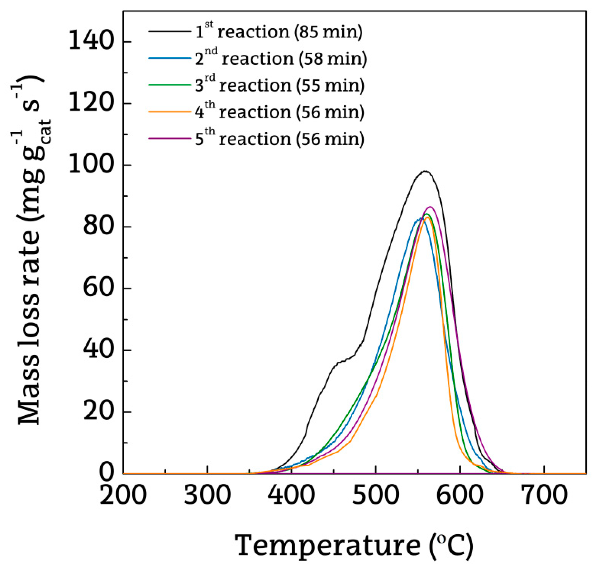
Figure 2 displays the evolution with time on stream of HDPE conversion (Figure 2a) and the yields of each product (Figure 2b), in the consecutive reaction-regeneration cycles. As observed, in the second reaction step (after the first reaction-regeneration cycle), the catalyst deactivation is faster than in the first one, with a faster decrease in conversion and H2 and CO2 yields with time on stream, and with a more pronounced increase in the yields of CH4, C2-C4 hydrocarbons and C5+ hydrocarbons. Thus, in the first reaction conversion decreases from 98% to 86% in 85 min time on stream, whereas in the second one it decreases from 98% to 87% in 58 min. The evolution of CO yield with time on stream is less pronounced than those of H2 and CO2 yields (Figure 2b), which is evidence that the catalyst deactivation affects more severely to the WGS reaction than to hydrocarbon reforming reactions. Thus, the evolutions of CO yields with time on stream during reaction-regeneration cycles do not differ much, with yields decreasing by 4.9% in the second cycle and by 4.7% in the last one. The increase in the catalyst deactivation rate in a reaction step subsequent to a reaction-regeneration cycle may be related to the expected irreversible deactivation of the catalyst, which progressively attenuates in the subsequent cycles. This effect may be attributed to two complementary causes: Firstly, to the greater coke formation capacity of Ni0 sites with larger particle size [41] and, secondly, to the higher concentration of hydrocarbons (coke precursors) [42,43] due to the decrease in the catalyst reforming activity. As observed in Figure 2b, due to the decrease in the activity of the catalyst for reforming, the yields of CH4, C2-C4, and non-converted C5+ hydrocarbons increase with time on stream. This trend is explained by the thermal cracking reactions of non-converted C5+ hydrocarbons to form CH4 and C2-C4 hydrocarbons, which take place in parallel with the reforming reactions; that is, the rate of reforming reactions decreases, and the formation of thermal cracking products is enhanced. It should be noted that the increase in the hydrocarbon yield in the first reaction cycle is linear for short times on stream, whereas it is exponential for long times on stream, which is evidence that an increase in the hydrocarbon yield has a significant influence on the higher catalyst deactivation rate. However, in the subsequent reactions, the evolution of hydrocarbons yield is exponential since the beginning of the reaction, which is evidence that the catalyst is deactivated at zero time on stream. This mechanism of deactivation enhanced by coke deposition due to the lower activity of the catalyst is also considered by Simson et al. [44] to explain that the deactivation by coke promotes an increase in the coke deposition rate.
Few catalyst deactivation studies focus on catalyst regeneration, particularly in fuel reforming processes. The aforementioned authors [44] investigated the regeneration of a Rh/Pt catalyst used in the steam reforming of ethanol/gasoline mixtures and concluded that after coke combustion the conversion at zero time on stream in the reaction steps is the same as with the fresh catalyst, but the deactivation rate increases as more reaction steps are carried out. Sanchez et al. [45] attribute the lower H2 selectivity of the catalyst after coke combustion to a small fraction of strongly adsorbed coke that may still remain on the catalyst surface. Montero et al. [46] also recovered a partial activity of the Ni-based catalyst used in the steam reforming of ethanol, suggesting the convenience of exploring reactivation methodologies for sintered Ni sites. In fact, there are other regeneration methods for coked catalysts, such as steam and CO2 treatments [47,48], but large amounts of CO are produced under these conditions. In order to compensate the irreversible deactivation, Zhao et al. [49] propose the impregnation of 1% Ni to the deactivated Ni/SiO2 catalysts instead of burning the coke. In the same way, Cheng et al. [50] concluded that new catalyst regeneration techniques including using diluents need to be developed.
The aforementioned results reveal a considerable effect of reaction-regeneration cycles on the stability of the catalyst, with no significant influence on gaseous product composition. As observed in Figure 3, the evolution of gaseous products concentration with time on stream remain almost constant in the successive cycles. Thus, H2 concentration at zero time on stream only decreases from 69.6% to 68.0% from the first to the fifth cycle. A similar trend is observed for CO2 concentration, decreasing 4.4% from the first to the last cycle, whereas CO concentration varies only 0.5%.
2.3. Deactivated Catalyst Characterization
The deactivated catalysts have been analyzed by TPO in order to study the content and nature of the coke deposited on the catalysts in the successive cycles. The TPO profiles for different cycles have been plotted in Figure 4. It should be noted that a sharp peak is observed at 550 °C in all the profiles, which is characteristic of the presence of structured coke [27,51]. Furthermore, a shoulder is also observed at low temperature (430 °C) in the profile corresponding to the first reaction cycle. The presence of two peaks is well-known in the TPO for Ni-based catalysts used in the steam reforming of CH4 [52,53], plastic pyrolysis volatiles [54,55] and oxygenates [56,57]. Coke formation and its evolution throughout reforming takes place via the contribution of the following steps: (i) Olefin polymerization to form encapsulating coke, which evolves to filamentous coke; (ii) dehydrogenation of CH4 to form filamentous coke; (iii) aromatic polycondensation to form highly structured coke; and (iv) Boudouard reaction to form filamentous coke [43,53]. Catalyst deactivation is attributed mainly to the blockage of Ni active sites by amorphous coke, whereas filamentous coke contributes to a lesser extent to deactivation because it has minor relation with Ni active sites and grows towards the outside of the catalyst particles [57]. Coke formation has also been reported as the main deactivating cause in the steam reforming of oxygenates [58,59].
It should be noted that the reaction time is different in each cycle, as the irreversible deactivation undergone by the catalyst during the first reaction hinders operation for longer times on stream in the subsequent cycles due to the low conversion obtained. In order to quantify the extent of coke deposition, the average coke deposition rate has been calculated as follow:
where Wcatalyst and Wcoke are the catalyst and coke masses, respectively, mHDPE the HDPE mass flow rate fed into the pyrolysis reactor and t the total reaction time in each run.
As observed in Table 1, the average coke deposition increases significantly from 1.6 mgcoke gHDPE−1 gcat−1 in the first reaction to 2.6 mgcoke gHDPE−1 gcat−1 in the third one, but in the subsequent reactions it increases only slightly. These results are consistent with the evolution of reaction indices with time on stream in the successive reaction-regeneration cycles observed in Figure 2, in which deactivation rate progressively attenuates.
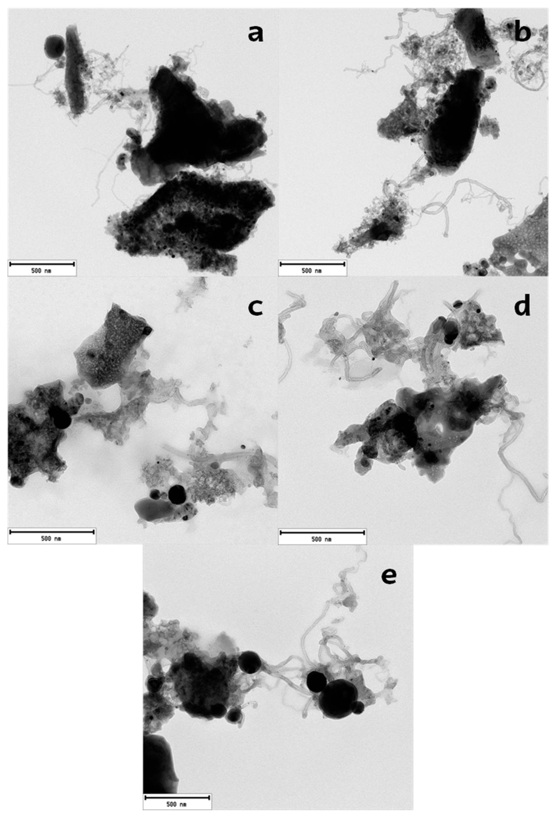
Figure 5 shows TEM images of the catalyst deactivated in different reaction-regeneration cycles. It should be noted that the coke deposited in all cycles has a structured configuration, with a significant presence of filamentous carbon, which explains the well-defined peaks observed in the TPO profiles (Figure 4). Several authors concluded that the presence of Ni metal particles and the interaction Ni-support was essential for the production of filamentous carbon [60,61]. In fact, previous studies showed that structured and filamentous coke are mainly formed in the reforming of polyolefin pyrolysis volatiles, whereas encapsulating coke is formed in the reforming of PET and PS pyrolysis volatiles [54].
2.4. Regenerated Catalyst Characterization
Studies of regeneration capability of reforming catalysts following reaction-regeneration cycles are essential for assessing the process potential. Accordingly, the characterization of the regenerated catalyst has been carried out by X-ray diffraction (XRD). Table 2 shows the Ni crystallite size determined for the catalyst at the different states, i.e., once it has been regenerated after each reaction step. These results have been calculated applying the equation by Debye-Scherred at 2θ = 52° corresponding to Ni0 (200) plane. As observed, the size increases as the number of reaction-regeneration cycles is increased. It is of note that these results are in good agreement with the Ni particle size evolution observed in TEM images (Figure 5). Furthermore, Ni sintering is evident in the first cycle and attenuates in the subsequent cycles. As aforementioned, Ni catalyst undergoes sintering in the steam reforming of HDPE pyrolysis volatiles at 700 °C [40]. However, the regeneration conditions may also be another cause of irreversible deactivation in this study due to the generation of “hot spots” on the catalyst surface by an increase in temperature above 700 °C when coke is oxidized, which causes catalyst sintering.
Ochoa et al. [40] concluded that deactivation of Ni catalyst in the steam reforming of HDPE pyrolysis volatiles steam reforming process is a consequence of structural and compositional changes of the catalyst, sintering of Ni particles, and deposition of coke, respectively. The complex mechanisms of catalyst deactivation bearing in mind the aforementioned issues involve the monitoring of encapsulating coke (main responsible for catalyst deactivation) towards filamentous coke, as well as Ni sintering. These authors calculated that Ni particles sinter at a rate of approximately 20 nm h−1. Other authors in the literature reveal that an increase in the Ni particle size favors coke deposition [62,63,64]. According to these authors’ statements, the deactivation rate is significant under severe operating conditions and reaction environments.
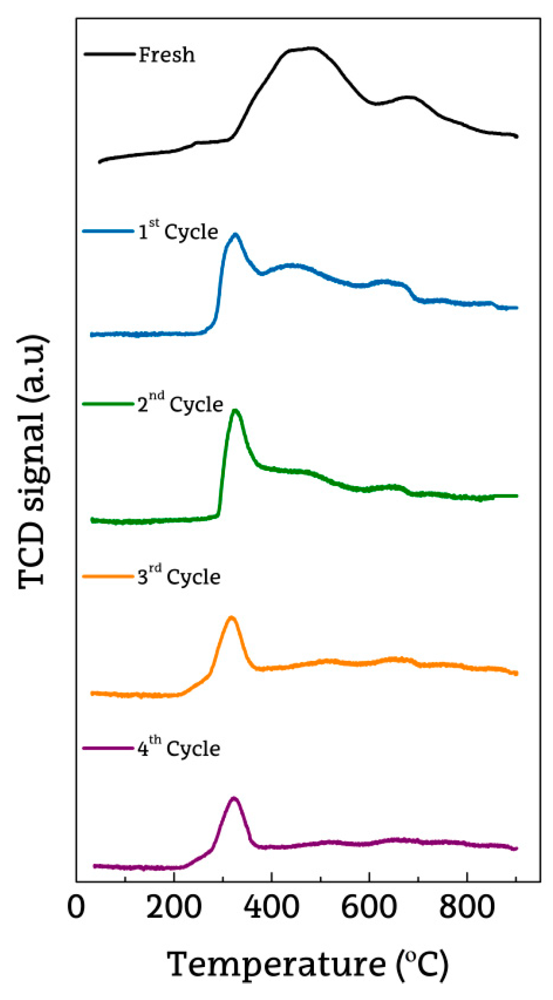
The sintering of Ni0 species in the catalyst has been confirmed by TPR analysis of the catalysts in different states (fresh and regenerated in the successive reaction-regeneration cycles) (Figure 6). In the TPR profile corresponding to the fresh catalyst, two peaks with different degrees of interaction with α-Al2O3 are observed; the main one at 550 °C associated with NiO reduction, and the second one at 700 °C related to Ni in the form of NiAl2O4 spinel [65,66]. After successive reaction-regeneration cycles, the peak at low-temperature shifts at a lower temperature, indicating a lower intensity of the metal-support interaction in the successive cycles. In addition, the NiAl2O4 spinel is not completely recovered with regeneration and gradually disappears in successive cycles. Figure 6 also reveals that the catalyst structure hardly changes subsequent to three reaction-regeneration cycles.
The aforementioned trend for the deterioration of the metal-support interaction, which is responsible for the sintering of Ni0 species in the catalyst during the reaction, is consistent with the results obtained in other catalyst characterization analyses (Figure 4 and Figure 5) and with those of catalyst activity recovery (Figure 1 and Figure 2). All results indicate that the catalyst approaches a pseudo-stable state with reproducible features and behavior in the reforming.
3. Materials and Methods
3.1. Materials and Analytical Techniques
High-density polyethylene (HDPE) was supplied by Dow Chemical, Spain, in the form of 4 mm virgin polymer chips. Polyolefins account for half of the plastics produced worldwide and are the major component in the municipal solid waste [1]. The properties of the HDPE provided have been reported elsewhere [24]. The commercial Ni catalyst was provided by Süd Chemie (G90LDP) and is made up of 14% NiO supported on aluminum oxide (Al2O3) doped with calcium. In order to use in the fluidized bed reactor, the catalyst was previously ground and sieved to 0.4–0.8 mm range. Prior to use in the reforming step, the catalyst was reduced at 710 °C under 10% H2 flow for 4 h. The complete reduction of the catalyst has been confirmed by XRD analysis of the fresh catalyst under these conditions. The physical properties of the catalyst, such as BET surface area (19 m2/g), pore volume (0.04 cm3/g) and average pore diameter (122 Å), were determined from N2 adsorption-desorption isotherms obtained in a Micromeritics ASAP 2010 analyzer (Norcross, GA, USA).
The catalysts at the different states (fresh, deactivated and regenerated) have been characterized based on several techniques and experimental procedures, as are: (i) Temperature programmed oxidation (TPO) in a Thermo Scientific TGA Q5000TA IR spectrometer (New Castle, DE, USA) to characterize the deactivated catalyst based on the properties of the coke deposited; (ii) transmission electron microscopy (TEM) images obtained using a Philips SuperTwin CM200 microscopy (Amsterdam, Netherlands), which allowed determining the morphology of the coke deposited on the deactivated catalysts; (iii) X-ray diffraction (XRD) of the fresh and regenerated catalysts using a Philips X’PERT PRO diffractometer (Amsterdam, Netherlands) to analyze the crystallite structure of the reduced catalyst and the average crystal size of Ni particles, which was calculated by Debye-Scherrer equation at 2θ = 52°, corresponding to Ni0 (200) plane; (iv) a temperature programmed reduction (TPR) in a Micromeritics Autochem 2920 analyzer (Norcross, GA, USA) in order to compare the reducibility of the fresh and regenerated catalysts and the nature of the metal phase.
3.2. Experimental Equipment and Conditions
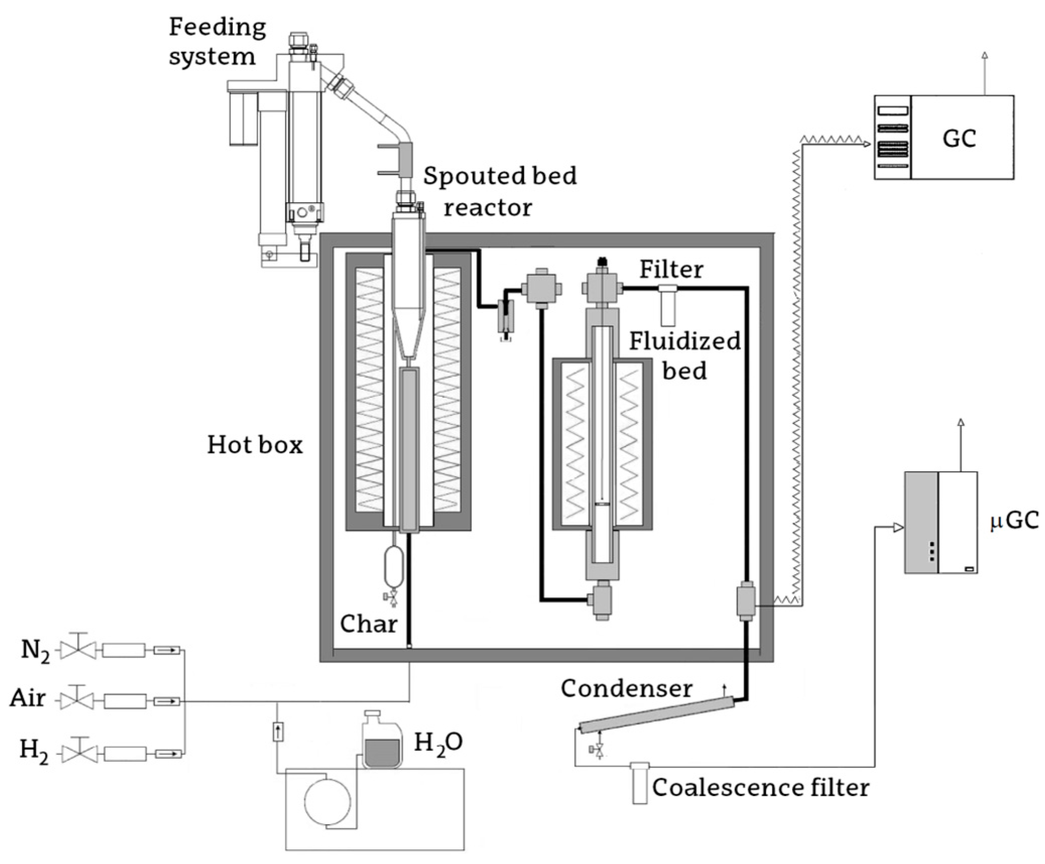
The pyrolysis-steam reforming of HDPE was carried out in a bench scale plant operating in a continuous regime, whose scheme is shown in Figure 7. The plant is made up of two reactors connected in-line, i.e., HDPE pyrolysis was carried out in a conical spouted bed reactor (CSBR) and the pyrolysis volatiles formed (gas and waxes) were transferred to a fluidized bed reactor for the steam reforming step. Suitable hydrodynamic conditions are required in both reactors because the same steam flow rate is used as both spouting and fluidizing agent. In order to ensure satisfactory spouting and fluidizing regimes in the first and second reactor, respectively, the particle sizes of the sand and catalyst were determined in previous studies [24,25].
Based on the previous experience acquired in the pyrolysis of HDPE in the CSBR, the following conditions were fixed [24]: 500 °C; mass of silica sand (particle diameter in the 0.3–0.355 mm range) 50 g; HDPE feeding rate, 0.75 g min−1; water flow rate, 3 mL min−1 (steam flow rate of 3.72 NL min−1), and steam/plastic ratio, 4 (S/C molar ratio of 3:1). The steam reforming of the pyrolysis volatiles in the fluidized reactor has been carried out under the following operating conditions: 700 °C and space time, 12.5 gcatalyst min gHDPE−1 (9.4 g of catalyst). It should be noted that the space time used in the reforming reaction is lower than that determined as optimum in previous studies, 16.7 gcatalyst min gHDPE−1 (12.5 g of catalyst), which was established in order to increase catalyst deactivation, and so it enables studying the regeneration of the catalyst. Once the catalyst has been deactivated, the reaction was stopped, a sample of the deactivated catalyst was taken for analysis, and the remaining amount was regenerated. It should be emphasized that the attrition of the catalyst was negligible under these conditions due to its good mechanical properties.
The product stream obtained by HDPE pyrolysis in a CSBR operating under the aforementioned conditions is mainly composed of waxes and diesel fraction, with an overall yield of 92 wt %, Table 3 [24]. Moreover, the composition of the stream remains constant, which is essential to study the subsequent reforming step, i.e., the effect operating conditions have on catalyst stability and its regenerability.
The regeneration between reactions was carried out by coke combustion in situ in the reforming reactor following temperature and air concentration ramps. Thus, regeneration was carried out for an initial period of 90 min at 600 °C by increasing O2 concentration (in N2) from 10 to 100 vol % in order to avoid sudden increases of temperature in the catalyst bed. Subsequently, the temperature was steadily increased to 700 °C in 60 min and kept at this value for another 60 min. Coke combustion was followed monitoring the concentration of CO2 at the reactor outlet, until full combustion of the coke was reached. At this point, another sample of the regenerated catalyst was taken for analysis.
Subsequent to the regeneration, the catalyst was reduced at the temperature determined by TPR. Based on the results obtained with the fresh catalyst, the catalyst reduction in the successive cycles was been carried out at 710 °C and a H2:N2 ratio of 10:90 vol. Once catalyst reduction had been finished, another sample of the reduced catalyst was been taken for analysis. This process was repeated for five consecutive reaction-regeneration cycles.
3.3. Reaction Indices
In order to evaluate G90LDP catalyst behavior, conversion and individual product yields were considered as reaction indices. HDPE conversion, XHDPE, has been defined as the ratio between the C units recovered in the gaseous product stream leaving the reforming reactor and those in the polymer fed into the pyrolysis reactor.
Similarly, the yields of C containing individual compounds in the gaseous product (CO2, CO, CH4, and C2-C4 hydrocarbons) have been calculated based on the HDPE fed into the pyrolysis reactor:
where, Fi, is the molar flow of each product i and FHDPE the molar flow of HDPE, both given in carbon units.
Regarding the hydrogen yield, it has been determined as the ratio between the molar flow of H2 produced (FH2) and the maximum molar flow of H2 allowable by stoichiometry (FH20), considering the stoichiometry of the Equation (5).
4. Conclusions
Nickel commercial catalyst is very active for hydrogen production from HDPE pyrolysis and the in-line steam reforming process, but it undergoes deactivation by coke deposition. The novelty of this process lies in the separation of pyrolysis and reforming steps, which provides high efficiency to the catalyst for the reforming of hydrocarbons, as there is no contact with fused plastic.
The deactivation of the Ni catalyst is mainly caused by coke deposition, whose precursors are the hydrocarbons in the reaction medium, especially C5+ ones (the main component in the feed into the reforming reactor). After coke combustion with air, the catalyst does not fully recover its activity, and its deactivation rate in the subsequent reaction is higher. By means of several analysis techniques, it has been determined that the irreversible deactivation of the catalyst used in successive reaction-regeneration cycles is due to the sintering of Ni species, with the consequent increase in their size. This phenomenon of sintering progressively attenuates in successive reaction-regeneration cycles and the catalyst approaches a pseudo-equilibrium state. In this state, the behavior of the catalyst is almost reproducible, which is very interesting for use of this commercial and low-cost catalyst for H2 production from plastic waste based on this two-step technology of pyrolysis and in-line reforming.
Author Contributions
Investigation, I.B., A.A. and L.S.; methodology, M.A. and G.L.; supervision, J.B. and M.O.
Funding
This research was funded by Ministry of Economy and Competitiveness of the Spanish Government (CTQ2016-75535-R (AEI/FEDER, UE) and CTQ2014-59574-JIN (AEI/FEDER, UE)), and the Basque Government (IT748-13).
Acknowledgments
I. Barbarias and A. Arregi thank the University of the Basque Country for their postgraduate grants (UPV/EHU 2016 and 2017, respectively).
Conflicts of Interest
The authors declare no conflict of interest. The funders had no role in the design of the study; in the collection, analyses, or interpretation of data; in the writing of the manuscript, or in the decision to publish the results.
References
- PlasticsEurope. Plastics-The Facts, 2017: An Analysis of European Plastics Production, Demand and Waste Data; PlasticsEurope: Brussels, Belgium, 2017. [Google Scholar]
- Al-Salem, S.M.; Lettieri, P.; Baeyens, J. Recycling and recovery routes of plastic solid waste (PSW): A review. Waste Manag. 2009, 29, 2625–2643. [Google Scholar] [CrossRef] [PubMed]
- Lopez, G.; Artetxe, M.; Amutio, M.; Bilbao, J.; Olazar, M. Thermochemical routes for the valorization of waste polyolefinic plastics to produce fuels and chemicals. A review. Renew. Sustain. Energy Rev. 2017, 73, 346–368. [Google Scholar] [CrossRef]
- Zhang, X.; Lei, H. Synthesis of high-density jet fuel from plastics via catalytically integral processes. RSC Adv. 2016, 6, 6154–6163. [Google Scholar] [CrossRef]
- Lopez, G.; Artetxe, M.; Amutio, M.; Alvarez, J.; Bilbao, J.; Olazar, M. Recent advances in the gasification of waste plastics. A critical overview. Renew. Sustain. Energy Rev. 2018, 82, 576–596. [Google Scholar] [CrossRef]
- Kumagai, S.; Yabuki, R.; Kameda, T.; Saito, Y.; Yoshioka, T. Simultaneous recovery of H2-Rich syngas and removal of HCN during pyrolytic recycling of polyurethane by Ni/Mg/Al catalysts. Chem. Eng. J. 2019, 361, 408–415. [Google Scholar] [CrossRef]
- Diaz-Silvarrey, L.S.; Zhang, K.; Phan, A.N. Monomer recovery through advanced pyrolysis of waste high density polyethylene (HDPE). Green Chem. 2018, 20, 1813–1823. [Google Scholar] [CrossRef]
- Lopez, G.; Olazar, M.; Amutio, M.; Aguado, R.; Bilbao, J. Influence of tire formulation on the products of continuous pyrolysis in a conical spouted bed reactor. Energy Fuels 2009, 23, 5423–5431. [Google Scholar] [CrossRef]
- Alvarez, J.; Hooshdaran, B.; Cortazar, M.; Amutio, M.; Lopez, G.; Freire, F.B.; Haghshenasfard, M.; Hosseini, S.H.; Olazar, M. Valorization of citrus wastes by fast pyrolysis in a conical spouted bed reactor. Fuel 2018, 224, 111–120. [Google Scholar] [CrossRef]
- Zhang, L.; Bao, Z.; Xia, S.; Lu, Q.; Walters, K.B. Catalytic pyrolysis of biomass and polymer wastes. Catalysts 2018, 8, 659. [Google Scholar] [CrossRef]
- Anuar Sharuddin, S.D.; Abnisa, F.; Wan Daud, W.M.A.; Aroua, M.K. A review on pyrolysis of plastic wastes. Energy Convers. Manag. 2016, 115, 308–326. [Google Scholar] [CrossRef]
- Al-Salem, S.M.; Antelava, A.; Constantinou, A.; Manos, G.; Dutta, A. A review on thermal and catalytic pyrolysis of plastic solid waste (PSW). J. Environ. Manag. 2017, 197, 177–198. [Google Scholar] [CrossRef] [Green Version]
- Santos, B.P.S.; Almeida, D.; Marques, M.d.F.V.; Henriques, C.A. Petrochemical feedstock from pyrolysis of waste polyethylene and polypropylene using different catalysts. Fuel 2018, 215, 515–521. [Google Scholar] [CrossRef]
- Olazar, M.; San José, M.J.; Aguayo, A.T.; Arandes, J.M.; Bilbao, J. Design factors of conical spouted beds and jet spouted beds. Ind. Eng. Chem. Res. 1993, 32, 1245–1250. [Google Scholar] [CrossRef]
- Elordi, G.; Olazar, M.; Aguado, R.; Lopez, G.; Arabiourrutia, M.; Bilbao, J. Catalytic pyrolysis of high density polyethylene in a conical spouted bed reactor. J. Anal. Appl. Pyrolysis 2007, 79, 450–455. [Google Scholar] [CrossRef]
- Wu, C.; Williams, P.T. Hydrogen production from the pyrolysis-gasification of polypropylene: Influence of steam flow rate, carrier gas flow rate and gasification temperature. Energy Fuels 2009, 23, 5055–5061. [Google Scholar] [CrossRef]
- Barbarias, I.; Lopez, G.; Artetxe, M.; Arregi, A.; Santamaria, L.; Bilbao, J.; Olazar, M. Pyrolysis and in-line catalytic steam reforming of polystyrene through a two-step reaction system. J. Anal. Appl. Pyrolysis 2016, 122, 502–510. [Google Scholar] [CrossRef]
- Arregi, A.; Amutio, M.; Lopez, G.; Artetxe, M.; Alvarez, J.; Bilbao, J.; Olazar, M. Hydrogen-rich gas production by continuous pyrolysis and in-line catalytic reforming of pine wood waste and HDPE mixtures. Energy Convers. Manag. 2017, 136, 192–201. [Google Scholar] [CrossRef]
- Miskolczi, N.; Sója, J.; Tulok, E. Thermo-catalytic two-step pyrolysis of real waste plastics from end of life vehicle. J. Anal. Appl. Pyrolysis 2017, 128, 1–12. [Google Scholar] [CrossRef]
- Czernik, S.; French, R.J. Production of hydrogen from plastics by pyrolysis and catalytic steam reform. Energy Fuels 2006, 20, 754–758. [Google Scholar] [CrossRef]
- Wu, C.; Williams, P.T. Ni/CeO2/ZSM-5 catalysts for the production of hydrogen from the pyrolysis–gasification of polypropylene. Int. J. Hydrogen Energy 2009, 34, 6242–6252. [Google Scholar] [CrossRef]
- Wu, C.; Williams, P.T. Hydrogen production by steam gasification of polypropylene with various nickel catalysts. Appl. Catal. B Environ. 2009, 87, 152–161. [Google Scholar] [CrossRef]
- Erkiaga, A.; Lopez, G.; Barbarias, I.; Artetxe, M.; Amutio, M.; Bilbao, J.; Olazar, M. HDPE pyrolysis-steam reforming in a tandem spouted bed-fixed bed reactor for H2 production. J. Anal. Appl. Pyrolysis 2015, 116, 34–41. [Google Scholar] [CrossRef]
- Barbarias, I.; Lopez, G.; Alvarez, J.; Artetxe, M.; Arregi, A.; Bilbao, J.; Olazar, M. A sequential process for hydrogen production based on continuous HDPE fast pyrolysis and in-line steam reforming. Chem. Eng. J. 2016, 296, 191–198. [Google Scholar] [CrossRef]
- Arregi, A.; Lopez, G.; Amutio, M.; Barbarias, I.; Bilbao, J.; Olazar, M. Hydrogen production from biomass by continuous fast pyrolysis and in-line steam reforming. RSC Adv. 2016, 6, 25975–25985. [Google Scholar] [CrossRef]
- Artetxe, M.; Lopez, G.; Amutio, M.; Barbarias, I.; Arregi, A.; Aguado, R.; Bilbao, J.; Olazar, M. Styrene recovery from polystyrene by flash pyrolysis in a conical spouted bed reactor. Waste Manag. 2015, 45, 126–133. [Google Scholar] [CrossRef] [PubMed]
- Barbarias, I.; Lopez, G.; Amutio, M.; Artetxe, M.; Alvarez, J.; Arregi, A.; Bilbao, J.; Olazar, M. Steam reforming of plastic pyrolysis model hydrocarbons and catalyst deactivation. Appl. Catal. A Gen. 2016, 527, 152–160. [Google Scholar] [CrossRef]
- Santamaria, L.; Lopez, G.; Arregi, A.; Amutio, M.; Artetxe, M.; Bilbao, J.; Olazar, M. Stability of different Ni supported catalysts in the in-line steam reforming of biomass fast pyrolysis volatiles. Appl. Catal. B Environ. 2019, 242, 109–120. [Google Scholar] [CrossRef]
- Yung, M.M.; Jablonski, W.S.; Magrini-Bair, K.A. Review of catalytic conditioning of biomass-derived syngas. Energy Fuels 2009, 23, 1874–1887. [Google Scholar] [CrossRef]
- Xie, H.; Yu, Q.; Yao, X.; Duan, W.; Zuo, Z.; Qin, Q. Hydrogen production via steam reforming of bio-oil model compounds over supported nickel catalysts. J. Energy Chem. 2015, 24, 299–308. [Google Scholar] [CrossRef]
- Fauteux-Lefebvre, C.; Abatzoglou, N.; Braidy, N.; Achouri, I.E. Diesel steam reforming with a nickel-alumina spinel catalyst for solid oxide fuel cell application. J. Power Sources 2011, 196, 7673–7680. [Google Scholar] [CrossRef]
- Morales-Cano, F.; Lundegaard, L.F.; Tiruvalam, R.R.; Falsig, H.; Skjøth-Rasmussen, M.S. Improving the sintering resistance of Ni/Al2O3 steam-reforming catalysts by promotion with noble metals. Appl. Catal. A Gen. 2015, 498, 117–125. [Google Scholar] [CrossRef]
- Bartholomew, C.H. Mechanisms of catalyst deactivation. Appl. Catal. A Gen. 2001, 212, 17–60. [Google Scholar] [CrossRef]
- Micheli, F.; Sciarra, M.; Courson, C.; Gallucci, K. Catalytic steam methane reforming enhanced by CO2 capture on CaO based bi-functional compounds. J. Energy Chem. 2017, 26, 1014–1025. [Google Scholar] [CrossRef]
- Rostrup-Nielsen, J.R. Catalytic steam reforming. Catal. Sci. Technol. 1984, 5, 1–117. [Google Scholar]
- Arandia, A.; Remiro, A.; García, V.; Castaño, P.; Bilbao, J.; Gayubo, A.G. Oxidative steam reforming of raw bio-oil over supported and bulk Ni catalysts for hydrogen production. Catalysts 2018, 8, 322. [Google Scholar] [CrossRef]
- Sperle, T.; Chen, D.; Lødeng, R.; Holmen, A. Pre-reforming of natural gas on a Ni catalyst. Criteria for carbon free operation. Appl. Catal. A Gen. 2005, 282, 195–204. [Google Scholar] [CrossRef]
- Sidjabat, O.; Trimm, D.L. Nickel-magnesia catalysts for the steam reforming of light hydrocarbons. Top. Catal. 2000, 11, 279–282. [Google Scholar] [CrossRef]
- Barbarias, I.; Artetxe, M.; Lopez, G.; Arregi, A.; Bilbao, J.; Olazar, M. Influence of the conditions for reforming HDPE pyrolysis volatiles on the catalyst deactivation by coke. Fuel Process. Technol. 2018, 171, 100–109. [Google Scholar] [CrossRef]
- Ochoa, A.; Barbarias, I.; Artetxe, M.; Gayubo, A.G.; Olazar, M.; Bilbao, J.; Castaño, P. Deactivation dynamics of a Ni supported catalyst during the steam reforming of volatiles from waste polyethylene pyrolysis. Appl. Catal. B Environ. 2017, 209, 554–565. [Google Scholar] [CrossRef]
- Christensen, K.O.; Chen, D.; Lødeng, R.; Holmen, A. Effect of supports and Ni crystal size on carbon formation and sintering during steam methane reforming. Appl. Catal. A Gen. 2006, 314, 9–22. [Google Scholar] [CrossRef]
- Angeli, S.D.; Pilitsis, F.G.; Lemonidou, A.A. Methane steam reforming at low temperature: Effect of light alkanes’ presence on coke formation. Catal. Today 2014, 242, 119–128. [Google Scholar] [CrossRef]
- Helveg, S.; Sehested, J.; Rostrup-Nielsen, J.R. Whisker carbon in perspective. Catal. Today 2011, 178, 42–46. [Google Scholar] [CrossRef]
- Simson, A.; Farrauto, R.; Castaldi, M. Steam reforming of ethanol/gasoline mixtures: Deactivation, regeneration and stable performance. Appl. Catal. B Environ. 2011, 106, 295–303. [Google Scholar] [CrossRef]
- Sanchez, E.A.; Comelli, R.A. Hydrogen by glycerol steam reforming on a nickel-alumina catalyst: Deactivation processes and regeneration. Int. J. Hydrogen Energy 2012, 37, 14740–14746. [Google Scholar] [CrossRef]
- Montero, C.; Remiro, A.; Arandia, A.; Benito, P.L.; Bilbao, J.; Gayubo, A.G. Reproducible performance of a Ni/La2O3–αAl2O3 catalyst in ethanol steam reforming under reaction–regeneration cycles. Fuel Process. Technol. 2016, 152, 215–222. [Google Scholar] [CrossRef]
- Zhang, Y.; Sun, G.; Gao, S.; Xu, G. Regeneration kinetics of spent FCC catalyst via coke gasification in a micro fluidized bed. Procedia Eng. 2015, 102, 1758–1765. [Google Scholar] [CrossRef]
- Bednarczuk, L.; Ramírez De La Piscina, P.; Homs, N. H2-production from CO2-assisted ethanol steam reforming: The regeneration of Ni-based catalysts. Int. J. Hydrogen Energy 2015, 40, 5256–5263. [Google Scholar] [CrossRef]
- Zhao, X.; Lu, G. Improving catalytic activity and stability by in-situ regeneration of Ni-based catalyst for hydrogen production from ethanol steam reforming via controlling of active species dispersion. Int. J. Hydrogen Energy 2016, 41, 13993–14002. [Google Scholar] [CrossRef]
- Cheng, S.; Wei, L.; Zhao, X.; Julson, J. Application, deactivation, and regeneration of heterogeneous catalysts in bio-oil upgrading. Catalysts 2016, 6, 83. [Google Scholar] [CrossRef]
- Acomb, J.C.; Wu, C.; Williams, P.T. Control of steam input to the pyrolysis-gasification of waste plastics for improved production of hydrogen or carbon nanotubes. Appl. Catal. B Environ. 2014, 147, 571–584. [Google Scholar] [CrossRef] [Green Version]
- Trimm, D.L. Coke formation and minimisation during steam reforming reactions. Catal. Today 1997, 37, 233–238. [Google Scholar] [CrossRef]
- Rostrup-Nielsen, J.; Trimm, D.L. Mechanisms of carbon formation on nickel-containing catalysts. J. Catal. 1977, 48, 155–165. [Google Scholar] [CrossRef]
- Barbarias, I.; Lopez, G.; Artetxe, M.; Arregi, A.; Bilbao, J.; Olazar, M. Valorisation of different waste plastics by pyrolysis and in-line catalytic steam reforming for hydrogen production. Energy Convers. Manag. 2018, 156, 575–584. [Google Scholar] [CrossRef]
- Wu, C.; Nahil, M.A.; Miskolczi, N.; Huang, J.; Williams, P.T. Processing real-world waste plastics by pyrolysis-reforming for hydrogen and high-value carbon nanotubes. Environ. Sci. Technol. 2014, 48, 819–826. [Google Scholar] [CrossRef] [PubMed]
- Arregi, A.; Lopez, G.; Amutio, M.; Artetxe, M.; Barbarias, I.; Bilbao, J.; Olazar, M. Role of operating conditions in the catalyst deactivation in the in-line steam reforming of volatiles from biomass fast pyrolysis. Fuel 2018, 216, 233–244. [Google Scholar] [CrossRef]
- Vicente, J.; Montero, C.; Ereña, J.; Azkoiti, M.J.; Bilbao, J.; Gayubo, A.G. Coke deactivation of Ni and Co catalysts in ethanol steam reforming at mild temperatures in a fluidized bed reactor. Int. J. Hydrogen Energy 2014, 39, 12586–12596. [Google Scholar] [CrossRef]
- Wang, A.; Lu, Y.; Yi, Z.; Ejaz, A.; Hu, K.; Zhang, L.; Yan, K. Selective production of γ-valerolactone and valeric acid in one-pot bifunctional metal catalysts. Chemistryselect 2018, 3, 1097–1101. [Google Scholar] [CrossRef]
- Yan, K.; Liu, Y.; Lu, Y.; Chai, J.; Sun, L. Catalytic application of layered double hydroxide-derived catalysts for the conversion of biomass-derived molecules. Catal. Sci. Technol. 2017, 7, 1622–1645. [Google Scholar] [CrossRef]
- Nahil, M.A.; Wu, C.; Williams, P.T. Influence of metal addition to Ni-based catalysts for the co-production of carbon nanotubes and hydrogen from the thermal processing of waste polypropylene. Fuel Process. Technol. 2015, 130, 46–53. [Google Scholar] [CrossRef] [Green Version]
- He, L.; Hu, S.; Jiang, L.; Liao, G.; Chen, X.; Han, H.; Xiao, L.; Ren, Q.; Wang, Y.; Su, S.; et al. Carbon nanotubes formation and its influence on steam reforming of toluene over Ni/Al2O3 catalysts: Roles of catalyst supports. Fuel Process. Technol. 2018, 176, 7–14. [Google Scholar] [CrossRef]
- Montero, C.; Ochoa, A.; Castaño, P.; Bilbao, J.; Gayubo, A.G. Monitoring Ni0 and coke evolution during the deactivation of a Ni/La2O3-αAl2O3 catalyst in ethanol steam reforming in a fluidized bed. J. Catal. 2015, 331, 181–192. [Google Scholar] [CrossRef]
- Serrano-Lotina, A.; Daza, L. Highly stable and active catalyst for hydrogen production from biogas. J. Power Sources 2013, 238, 81–86. [Google Scholar] [CrossRef]
- Fakeeha, A.H.; Barama, S.; Ibrahim, A.A.; Al-Otaibi, R.; Barama, A.; Abasaeed, A.E.; Al-Fatesh, A.S. In situ regeneration of alumina-supported Cobalt–iron catalysts for hydrogen production by catalytic methane decomposition. Catalysts 2018, 8, 567. [Google Scholar] [CrossRef]
- Rynkowski, J.M.; Paryjczak, T.; Lenik, M. On the nature of oxidic nickel phases in NiO/γ-Al2O3 catalysts. Appl. Catal. A Gen. 1993, 106, 73–82. [Google Scholar] [CrossRef]
- Seo, J.G.; Youn, M.H.; Park, S.; Song, I.K. Effect of calcination temperature of mesoporous alumina xerogel (AX) supports on hydrogen production by steam reforming of liquefied natural gas (LNG) over Ni/AX catalysts. Int. J. Hydrogen Energy 2008, 33, 7427–7434. [Google Scholar] [CrossRef]
Figure 1.
Evolution of conversion (a) and the yields of H2 (b), CO2 (c), CO (d), CH4 (e), C2-C4 hydrocarbon (f), and C5+ hydrocarbons (g) at zero time on stream in successive reaction-regeneration cycles.
Figure 1.
Evolution of conversion (a) and the yields of H2 (b), CO2 (c), CO (d), CH4 (e), C2-C4 hydrocarbon (f), and C5+ hydrocarbons (g) at zero time on stream in successive reaction-regeneration cycles.

Figure 2.
Evolution of high-density polyethylene (HDPE) conversion (a) and product yields (b) in the successive reaction-regeneration cycles with time on stream.
Figure 2.
Evolution of high-density polyethylene (HDPE) conversion (a) and product yields (b) in the successive reaction-regeneration cycles with time on stream.

Figure 3.
Evolution of the gaseous product composition with time on stream for five consecutive reaction-regeneration cycles.
Figure 3.
Evolution of the gaseous product composition with time on stream for five consecutive reaction-regeneration cycles.

Figure 4.
TPO profiles of the catalysts deactivated in the reaction steps in five consecutive reaction-regeneration cycles.
Figure 4.
TPO profiles of the catalysts deactivated in the reaction steps in five consecutive reaction-regeneration cycles.

Figure 5.
TEM images of the catalyst used in five consecutive reaction-regeneration cycles; (a) 1st cycle; (b) 2nd cycle; (c) 3rd cycle; (d) 4th cycle; (e) 5th cycle.
Figure 5.
TEM images of the catalyst used in five consecutive reaction-regeneration cycles; (a) 1st cycle; (b) 2nd cycle; (c) 3rd cycle; (d) 4th cycle; (e) 5th cycle.

Figure 6.
TPR profiles of the catalyst regenerated subsequent to four consecutive reaction cycles.

Figure 7.
Scheme of the pyrolysis-reforming bench scale unit.


Table 1.
Average coke deposition for five consecutive reaction-regeneration cycles.
| Cycles | |
|---|---|
| 1st (85 min) | 1.6 |
| 2nd (58 min) | 2.1 |
| 3rd (55 min) | 2.6 |
| 4th (56 min) | 2.7 |
| 5th (56 min) | 2.9 |
Table 2.
Evolution of Ni crystallite size of the catalyst regenerated in five consecutive reaction-regeneration cycles.
Table 2.
Evolution of Ni crystallite size of the catalyst regenerated in five consecutive reaction-regeneration cycles.
| Cycles | Crystallite Size, nm |
|---|---|
| 0 * | 25 |
| 1st | 62 |
| 2nd | 72 |
| 3rd | 81 |
| 4th | 80 |
* Fresh catalyst.
Table 3.
Mass composition (wt %) of volatiles from HDPE pyrolysis.
| Fraction | Compound | Yield (wt %) |
|---|---|---|
| Gas | 1.50 | |
| Alkanes | 0.4 | |
| Alkenes | 1.1 | |
| Oil | 31.5 | |
| C5-C11 | 5.9 | |
| C12-C20 | 25.6 | |
| Solid | 67.0 | |
| Light waxes (C21-C40) | 29.5 | |
| Heavy waxes (C40+) | 37.5 |
© 2019 by the authors. Licensee MDPI, Basel, Switzerland. This article is an open access article distributed under the terms and conditions of the Creative Commons Attribution (CC BY) license (http://creativecommons.org/licenses/by/4.0/).
Share and Cite
MDPI and ACS Style
Barbarias, I.; Artetxe, M.; Lopez, G.; Arregi, A.; Santamaria, L.; Bilbao, J.; Olazar, M. Catalyst Performance in the HDPE Pyrolysis-Reforming under Reaction-Regeneration Cycles. Catalysts 2019, 9, 414. https://doi.org/10.3390/catal9050414
AMA Style
Barbarias I, Artetxe M, Lopez G, Arregi A, Santamaria L, Bilbao J, Olazar M. Catalyst Performance in the HDPE Pyrolysis-Reforming under Reaction-Regeneration Cycles. Catalysts. 2019; 9(5):414. https://doi.org/10.3390/catal9050414
Chicago/Turabian StyleBarbarias, Itsaso, Maite Artetxe, Gartzen Lopez, Aitor Arregi, Laura Santamaria, Javier Bilbao, and Martin Olazar. 2019. "Catalyst Performance in the HDPE Pyrolysis-Reforming under Reaction-Regeneration Cycles" Catalysts 9, no. 5: 414. https://doi.org/10.3390/catal9050414
Note that from the first issue of 2016, this journal uses article numbers instead of page numbers. See further details here.