
Modeling of a Two-Bed Reactor for Low-Temperature Removal of Nitrogen Oxides in Nitric Acid Production
 ,
,
Abstract
:
1. Introduction
- -
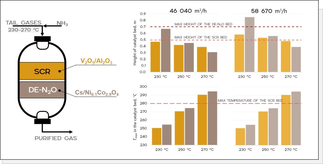
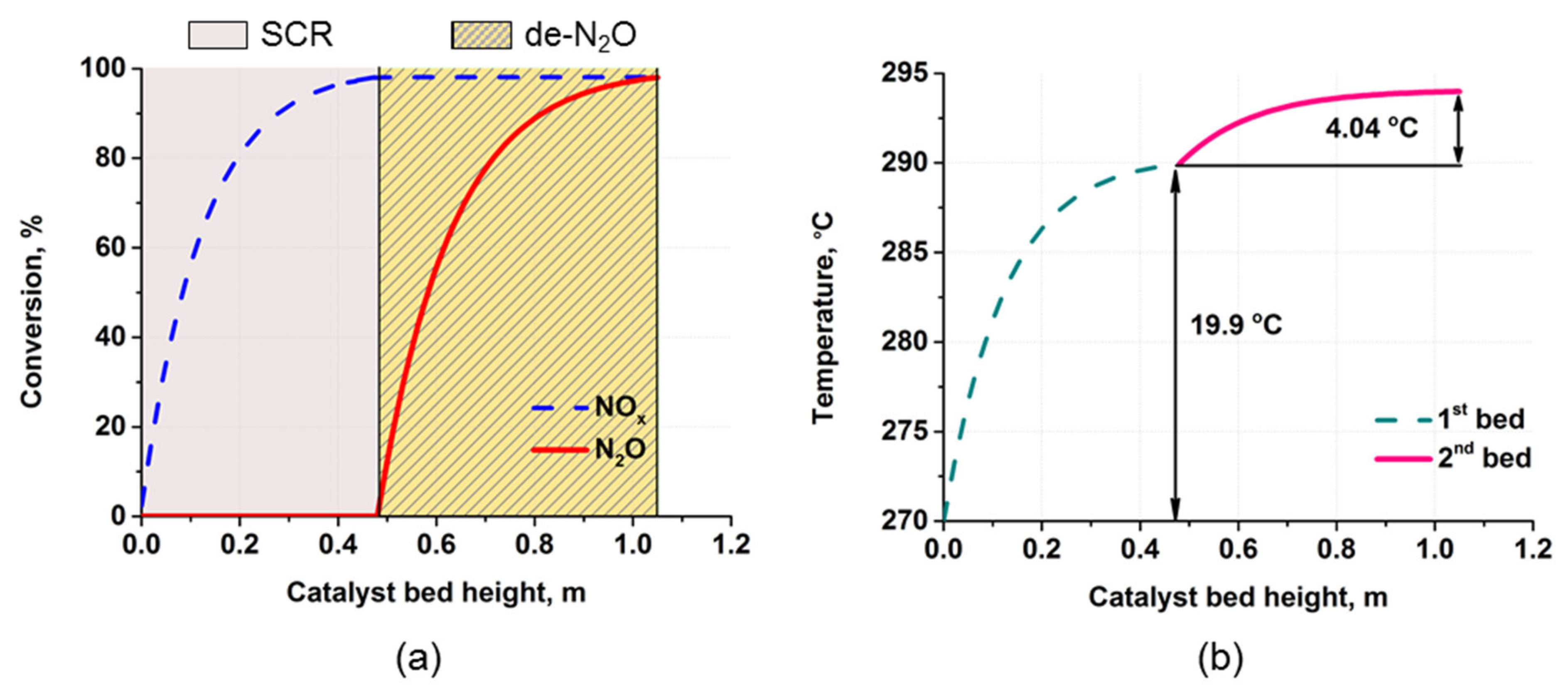
- The catalyst bed height should not exceed the maximum allowable space according to the UKL plant’s catalytic purification reactor design: 0.5 m for SCR and 0.7 m for de-N2O;
- -
- The maximum temperature in the SCR catalyst bed should not exceed 280 °C because the selectivity of vanadium–aluminum catalysts decreases at a higher temperature.
2. Results and Discussion
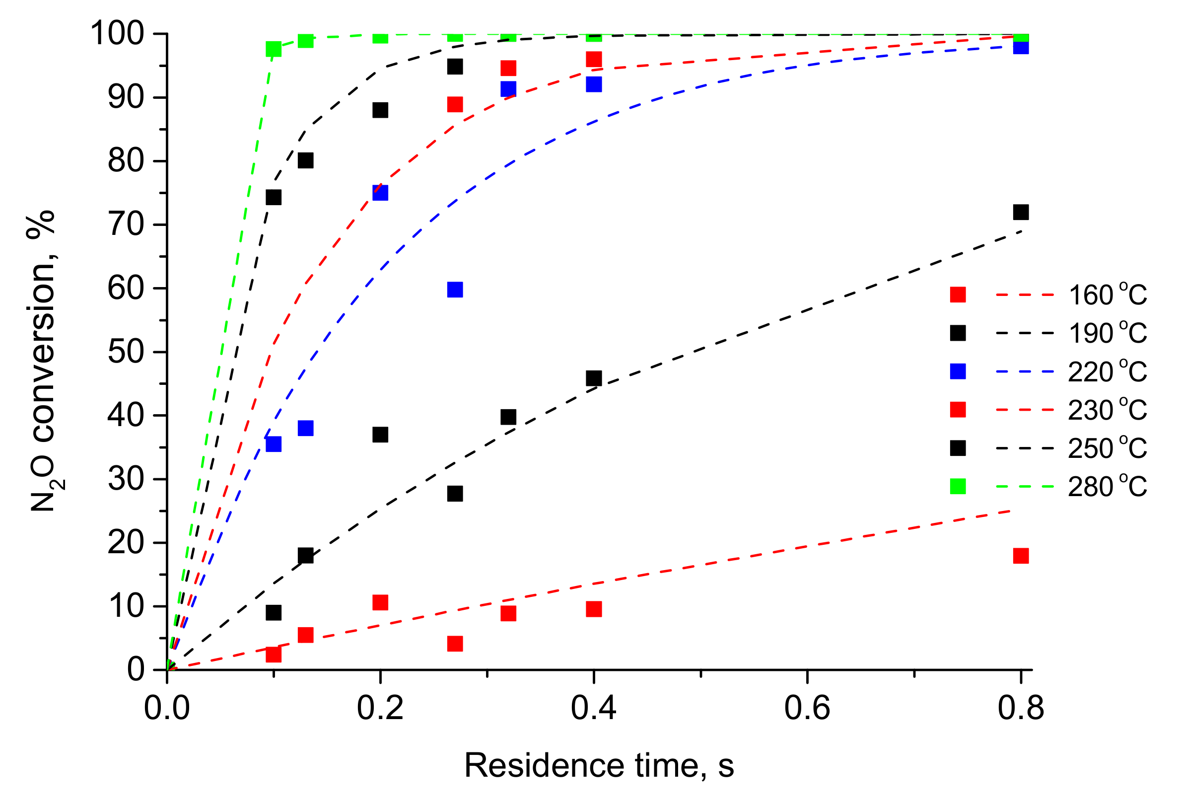
2.1. Kinetic Modeling
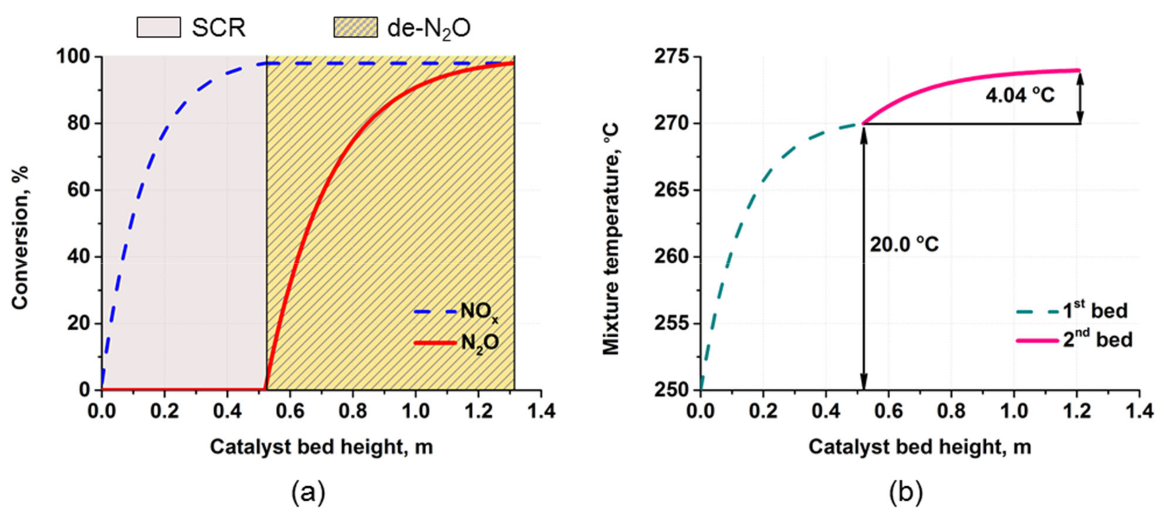
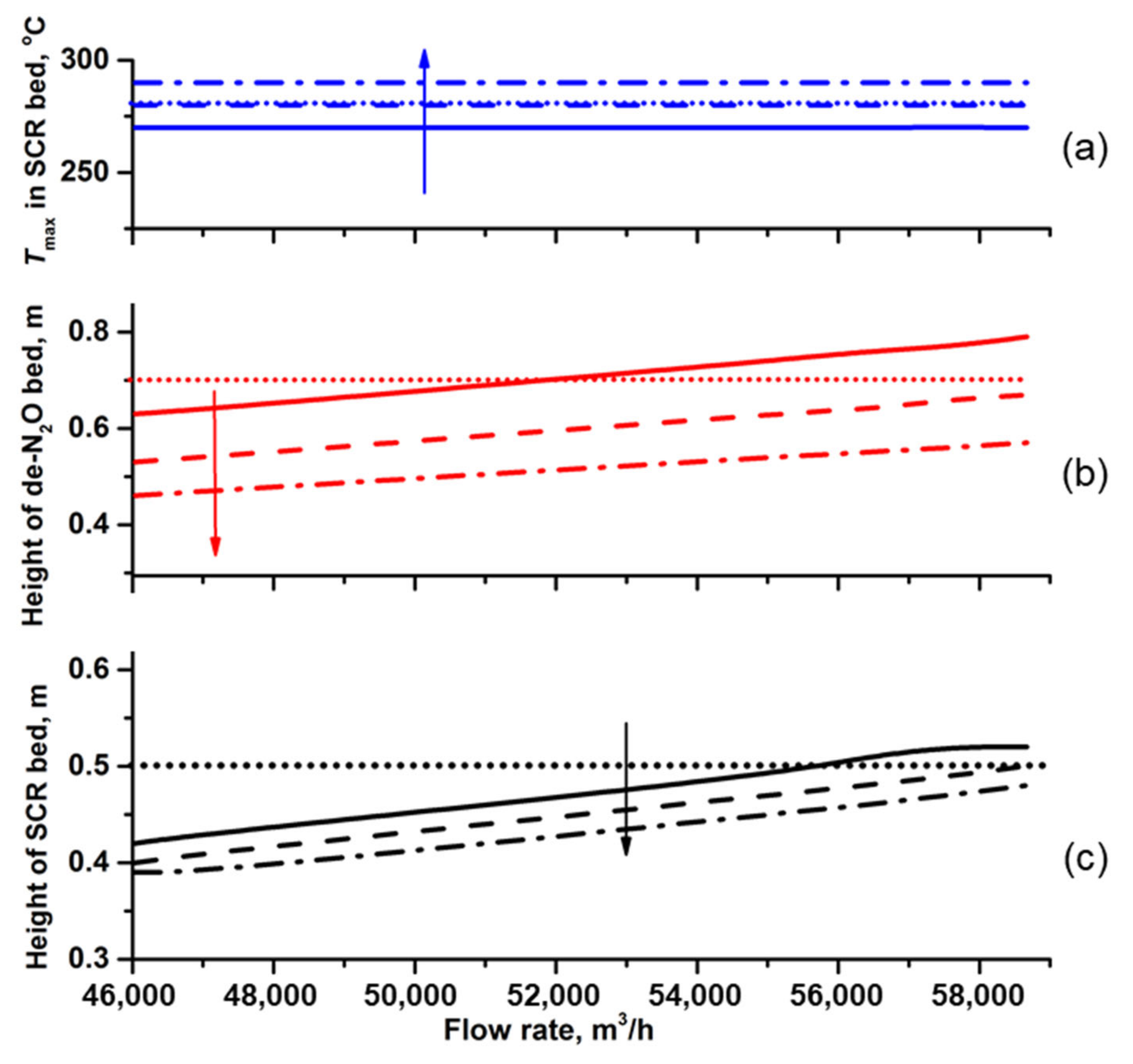
2.2. Process Modeling
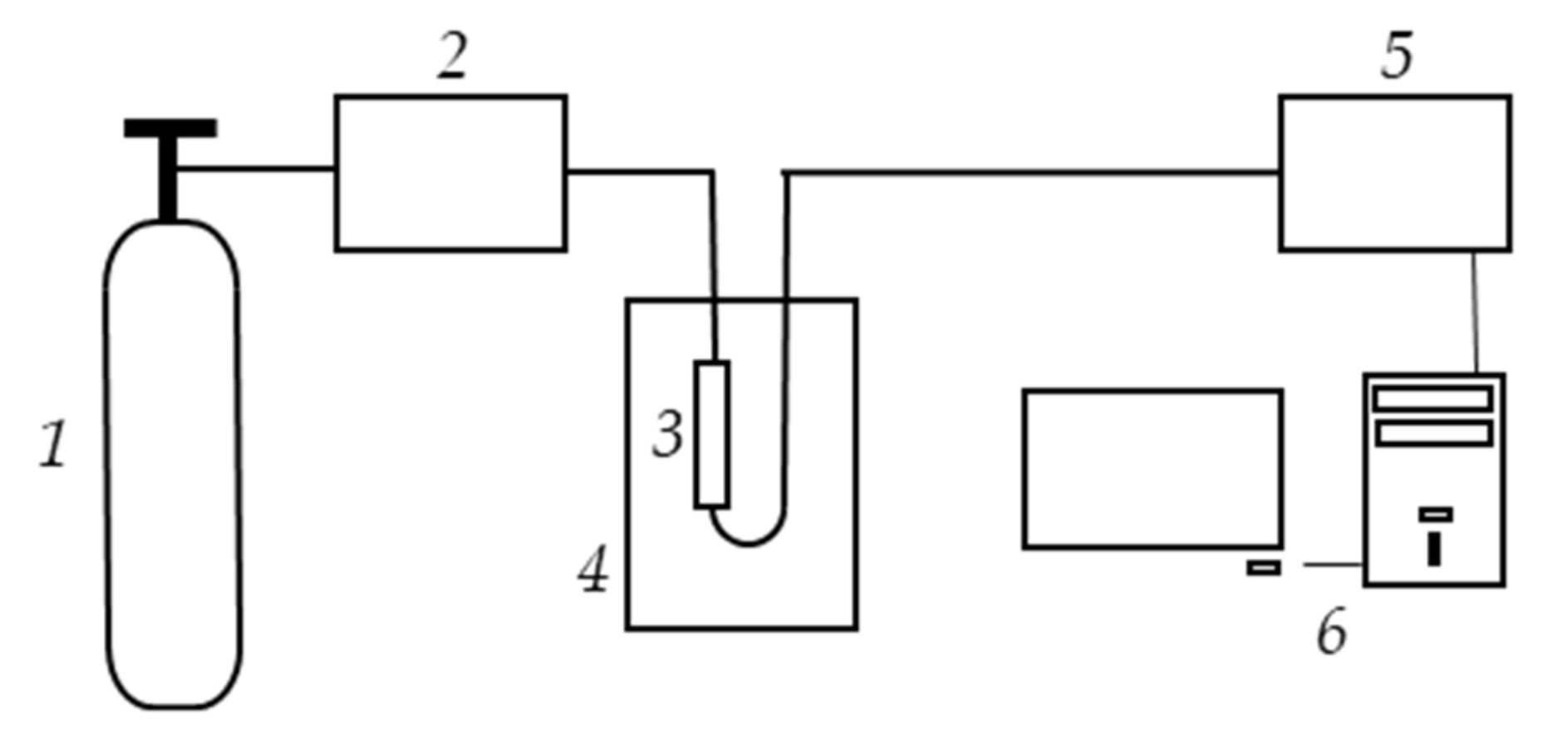
3. Experimental
4. Mathematical Model
4.1. Description of the Reaction System and Governing Equations of the Model
- -
- Convective heat and mass transfers in the gas phase;
- -
- Axial diffusion in the gas phase;
- -
- Axial heat transfer due to thermal conductivity in the solid phase;
- -
- Interphase heat and mass transfers;
- -
- Chemical reactions (SCR of NOx with ammonia in the first bed, N2O decomposition in the second bed);
- -
- Heat release as a result of exothermic reactions in the solid phase.
4.2. Governing Equations of the Model
4.3. Input Data for the Calculations
- -
- Inlet temperature (): 230–270 °C;
- -
- Gas flow rate (Q): 46,040–58,670 m3/h (STP), which corresponds to the linear velocity of 1.128–1.437 m/s.
- -
- Reactor diameter: 3.8 m;
- -
- Gas composition at the inlet to the first bed (vol.%): NOx—0.15, NH3—0.165, N2O—0.15, oxygen—5, water—2, and nitrogen—by balance;
- -
- Working pressure: 0.716 MPa.
- -
- -
- The maximum temperature in the SCR catalyst bed (Tmax) should not exceed 280 °C because the selectivity of aluminum–vanadium catalysts decreases at a higher temperature;
- -
- The emissions of NOx and N2O at the reactor outlet should be less than 50 ppm, which, at the preset inlet concentrations of nitrogen oxides, corresponds to a conversion rate of not less than 98%.
5. Conclusions
Author Contributions
Funding
Data Availability Statement
Conflicts of Interest
Nomenclatures
| B | Constant (0.0643); |
| CNOx(N2O) | Concentration of NOx (N2O), mol/m3; |
| cp | Gas heat capacity, J∙m−3∙K−1; |
| dp | Catalyst diameter, mm; |
| DK | Knudsen diffusion coefficient, m2/s; |
| D | Diffusion coefficient, m2/s; |
| Dm | Coefficient of molecular diffusion, m2/s; |
| Ea | Activation energy, J/mol; |
| G | Catalyst loading, kg; |
| (−∆Hj) | Enthalpy of j-th reaction, J/mol; |
| H | Catalyst bed height, m; |
| k0 | Pre-exponential factor, s−1; |
| k | Rate constant, s−1; |
| M | Molecular weight of N2O, g/mol; |
| P | Pressure, Pa; |
| P0 | Pressure at STP, Pa; |
| ∆P | Pressure drop, Pa; |
| Pe | Catalyst permeability; |
| Q | Volumetric flow rate, m3/h; |
| rp | Pore radius, m; |
| Ssp | Specific surface area, m−1; |
| T | Temperature, K; |
| T0 | Temperature at STP, K; |
| Tref | Reference temperature, K; |
| ΔTad | Adiabatic temperature, K; |
| u0 | Linear velocity at STP, m/s; |
| V | Catalyst volume, m3; |
| Vm | Molar volume at STP, m3/mol; |
| W | Rate of reaction, mol·m−3·s−1; |
| X | Conversion,%; |
| yi | Concentration of i-th component, mole fraction; |
| z | Axial coordinate, m. |
| Greek letters: | |
| α | Coefficient of heat exchange, W·m−2·K−1; |
| β | Coefficient of mass exchange, m/s; |
| γ | Bulk density, kg/m3; |
| ε | Porosity; |
| η | Effectiveness factor; |
| λ | Thermal conductivity, W·m−1·K−1; |
| μ | Dynamic viscosity, kg·m−1·s−1; |
| νi | Stoichiometric coefficients; |
| τ | Residence time, s; |
| ψ | Thiele modulus. |
| Subscripts: | |
| c | Catalyst; |
| g | Gas; |
| max | Maximum value. |
| Superscripts: | |
| e | Effective value; |
| in | Inlet; |
| out | Outlet. |
| Dimensionless groups: | |
| Nu | Nusselt number; |
| Pe | Peclet number; |
| Pr | Prandtl number; |
| Re | Reynolds number; |
| Rem | Modified Reynolds number; |
| Sc | Schmidt number; |
| Sh | Sherwood number. |
References
- Pérez-Ramirez, J.; Kapteijn, F.; Schöffel, K.; Moulijn, J.A. Formation and control of N2O in nitric acid production: Where do we stand today? Appl. Catal. 2003, 44, 117–151. [Google Scholar] [CrossRef]
- Boll, W. Prolonged campaign length of high pressure nitric acid plant by optimization of secondary catalyst design for N2O abatement. In Proceedings of the Int. Conf. & Exhib Nitrogen+Syngas 2017, London, UK, 27 February 2017. [Google Scholar]
- Groves, M.C.E.; Sasonow, A. Uhde EnviNOx® technology for NOX and N2O abatement: A contribution to reducing emissions from nitric acid plants. J. Integr. Environ. Sci. 2010, 7, 211–222. [Google Scholar] [CrossRef] [Green Version]
- EPA December 2010. Available and Emerging Technologies for Reducing Greenhouse Gas Emissions from Nitric Acid Production Industry. Available online: https://www.epa.gov/sites/production/files/2015-12/documents/nitricacid.pdf (accessed on 13 January 2023).
- Chumachenko, V.A.; Isupova, L.A.; Ivanova, Y.A.; Ovchinnikova, E.V.; Reshetnikov, S.I.; Noskov, A.S. Technologies for Simultaneous Low-Temperature Catalytic Removal of NOx and N2O from the Tail Gases of Nitric Acid Plants. Chem. Sustain. Dev. 2020, 28, 203–212. [Google Scholar] [CrossRef]
- Chumachenko, V.A.; Zenkovets, G.A.; Shutilov, A.A.; Kharitonov, A.S.; Pirutko, L.V.; Mokrinsky, V.V.; Noskov, A.S. Low-temperature abatement of nitrogen oxides (NOx, N2O) from the effluent gases in nitric acid production. In Proceedings of the XIX Int. Conf. on Chemical Reactors (CHEMREACTOR-19), Vienna, Austria, 5 September 2010. [Google Scholar]
- Zenkovets, G.A.; Shutilov, A.A.; Ivanova, G.G.; Slavinskaya., E.M.; Chumachenko, V.A.; Noskov, A.S. Catalyst, method of its preparation and method of purification of tail gases from nitrogen oxides. Patent RU 2647847 C1, 22 May 2017. [Google Scholar]
- Kladova, N.V.; Borisova, T.V.; Makarenko, M.G.; Chumachenko, V.A. Aluminum-vanadium catalyst for selective purification from nitrogen oxides with ammonia and method for its production. Patent RU 2167708 C1, 3 March 2000. [Google Scholar]
- Yu, H.; Wang, X. Apparent activation energies and reaction rates of N2O decomposition via different routes over Co3O. Catal. Commun. 2018, 106, 40–43. [Google Scholar] [CrossRef]
- Kapteijn, F.; Marban, G.; Rodriguez-Mirasol, J.; Moulijn, J.A. Kinetic Analysis of the Decomposition of Nitrous Oxide over ZSM-5 Catalysts. J. Catal. 1997, 167, 256–265. [Google Scholar] [CrossRef]
- Dandl, H.; Emig, G. Mechanistic approach for the kinetics of the decomposition of nitrous oxide over calcined hydrotalcites. Appl. Catal. A Gen. 1998, 168, 261–268. [Google Scholar] [CrossRef]
- Isupova, L.A.; Ivanova, Y.A. Removal of nitrous oxide in nitric acid production. Kinet. Catal. 2019, 60, 744–760. [Google Scholar] [CrossRef]
- Konsolakis, M. Recent advances on nitrous oxide (N2O) decomposition over non–noble metal oxide catalysts: Catalytic performance, mechanistic considerations and surface chemistry aspects. ACS Catal. 2015, 5, 1–87. [Google Scholar] [CrossRef]
- Yu, H.; Qi, X.; Du, X.; Pan, Y.; Feng, X.; Shan, W.; Xiong, Y. The preparation of 3.0F-Co3O4 catalyst with “Yardang Landform” structure and its performance for catalyzing N2O decomposition. Mol. Catal. 2023, 537, 112960. [Google Scholar] [CrossRef]
- Choi, S.; Nam, K.B.; Ha, H.P.; Kwon, D.W. Enhancement of Catalytic N2O Decomposition by Modulating Oxygen Vacancies over Cu/Ce1-XYX Catalysts. J. Ind. Eng. Chem. 2023; in press. [Google Scholar] [CrossRef]
- Qi, J.; Qi, X.; Pan, Y.; Cui, J.; Xiong, Y.; Shan, W.; Yu, H. Sm doped NiO catalysts with excellent H2O resistance for N2O decomposition under simulated nitric acid plant exhaust condition. Appl. Surf. Sci. 2023, 611, 155657. [Google Scholar] [CrossRef]
- Klegova, A.; Pacultova, K.; Kiska, T.; Peikertova, P.; Rokicinska, A.; Kustrowski, P.; Obalova, L. Washcoated open-cell foam cobalt spinel catalysts for N2O decomposition. Mol. Catal. 2022, 533, 112754. [Google Scholar] [CrossRef]
- Xiong, Y.; Zhao, Y.; Shan, W.; Feng, X.; Cui, J.; Lou, Z.; Shao, G.; Dong, M.; Yu, H. Potassium promoted Gd0.06Co catalysts for highly efficient catalytic N2O decomposition in presence of impurity gases at low temperature. Chemosphere 2022, 303, 135257. [Google Scholar] [CrossRef]
- Ma, Z.; Ren, Y.; Lu, Y.B.; Peter, P.G. Catalytic decomposition of N2O on ordered crystalline metal oxides. J. Nanosci. Nanotechnol 2013, 13, 5093–5103. [Google Scholar] [CrossRef]
- Hu, X.; Wang, Y.; Wu, R.; Zhao, Y. Graphitic carbon nitride-supported cobalt oxides as a potential catalyst for decomposition of N2O. Appl. Surf. Sci. 2021, 538, 148157. [Google Scholar] [CrossRef]
- Yan, L.; Ren, T.; Wang, X.; Ji, D.; Suo, J. Catalytic decomposition of N2O over MxCo1−xCo2O4 (M = Ni, Mg) spinel oxides. Appl. Catal. B Env. 2003, 45, 85–90. [Google Scholar] [CrossRef]
- Liu, Z.; He, F.; Ma, L.; Peng, S. Recent Advances in Catalytic Decomposition of N2O on Noble Metal and Metal Oxide. Catal. Catal. Surv. Asia 2016, 20, 121–132. [Google Scholar] [CrossRef]
- Zheng, L.; Li, H.-J.; Xu, X.-F. Catalytic decomposition of N2O over Mg-Co composite oxides hydrothermally prepared by using carbon sphere as template. J. Fuel Chem. Technol. 2018, 46, 569–577. [Google Scholar] [CrossRef]
- Zhang, H.-J.; Wang, J.; Xu, X.-F. Catalytic decomposition of N2O over NixCo1–xCoAlO4 spinel oxides prepared by sol-gel method. J. Fuel Chem. Technol. 2015, 43, 81–87. [Google Scholar] [CrossRef]
- Russo, N.; Fino, D.; Saracco, G.; Specchia, V. N2O catalytic decomposition over various spinel-type oxides. Catal. Today 2007, 119, 228–232. [Google Scholar] [CrossRef]
- Abu-Zied, B.M.; Soliman, S.A.; Abdellah, S.E. Pure and Ni-substituted Co3O4 spinel catalysts for direct N2O decomposition. Chin. J. Catal. 2014, 35, 1105–1112. [Google Scholar] [CrossRef]
- Krezhov, K.; Konstantinov, P. Cationic distributions in the binary oxide spinels MxCo3−xO4 (M = Mg,Cu,Zn,Ni). Phys. B Cond. Matter 1997, 234–236, 157–158. [Google Scholar] [CrossRef]
- Wójcik, S.; Grzybek, G.; Stelmachowski, P.; Sojka, Z.; Kotarba, A. Bulk, Surface and Interface Promotion of Co3O4 for the Low-Temperature N2O Decomposition Catalysis. Catalysts 2020, 10, 41. [Google Scholar] [CrossRef] [Green Version]
- Stelmachowski, P.; Maniak, G.; Kotarba, A.; Sojka, Z. Strong electronic promotion of Co3O4 towards N2O decomposition by surface alkali dopants. Catal. Commun. 2009, 10, 1062–1065. [Google Scholar] [CrossRef]
- Maniak, G.; Stelmachowski, P.; Kotarba, A.; Sojka, Z.; Rico-Pérez, V.; Bueno-López, A. Rationales for the selection of the best precursor for potassium doping of cobalt spinel based de-N2O catalyst. Appl. Catal. B Env. 2013, 136–137, 302–307. [Google Scholar] [CrossRef]
- Ivanova, Y.A.; Ivanov, D.A.; Chumachenko, V.A.; Isupova, L.S.; Noskov, A.S. One-reactor scheme for NO and N2O low-temperature abatement from tail gas in nitric acid production. In Proceedings of the XXII International Conference on Chemical Reactors (CHEMREACTOR-22), London, UK, 19 September 2016. [Google Scholar]
- Ivanova, Y.A.; Sutormina, E.F.; Isupova, L.A. Low-temperature decomposition of nitrous oxide in the presence of 1%Cs/MgxCo3–xO4 (x = 0–0.9) Oxides. Kinet. Catal. 2020, 61, 646–653. [Google Scholar] [CrossRef]
- Ivanova, Y.A.; Sutormina, E.F.; Isupova, L.A.; Rogov, V.A. Effect of the Composition of NixCo3–xO4 (x = 0–0.9) Oxides on Their Catalytic Activity in the Low-Temperature Reaction of N2O Decomposition. Kinet. Catal. 2018, 59, 357–362. [Google Scholar] [CrossRef]
- Obalová, L.; Jirátová, K.; Karásková, K.; Kovanda, F. Simulation of N2O abatement in waste gases by its decomposition over a K-promoted Co-Mn-Al mixed oxide catalyst. Chin. J. Catal. 2011, 32, 816–820. [Google Scholar] [CrossRef]
- Walter, S.; Malmberg, S.; Schmidt, B.; Liauw, M.A. Mass transfer limitations in microchannel reactors. Catal. Today 2005, 110, 15–25. [Google Scholar] [CrossRef]
- Rossetti, I. Continuous flow (micro-) reactors for heterogeneously catalyzed reactions: Main design and modelling issues. Catal. Today 2018, 308, 20–31. [Google Scholar] [CrossRef]
- Perez-Ramires, J.; Berger, R.J.; Mul, G.; Kapteijn, F.; Moulijn, J.A. The six-flow reactor technology. A review on fast catalyst screening and kinetic studies, Catal. Today 2000, 60, 93–109. [Google Scholar] [CrossRef]
- Aerov, M.E.; Todes, O.M.; Narinsky, D.A. Apparatuses with a Stationary Granular Beds, 1st ed.; Khimiya: Leningrad, Russia, 1979; pp. 1–176. [Google Scholar]
- Ovchinnikova, E.V.; Vernikovskaya, N.V.; Gribovskii, A.G.; Chumachenko, V.A. Multichannel microreactors for highly exothermic catalytic process: The influence of thermal conductivity of reactor material and of transport phenomena inside the channels on the process efficiency. Chem. Eng. J. 2021, 409, 128046. [Google Scholar] [CrossRef]
- Yagi, S.; Wakao, N. Heat and mass transfer from wall to fluid in packed beds. AIChE J. 1959, 5, 79–85. [Google Scholar] [CrossRef]
- Yagi, S.; Kunii, D.; Wakao, N. Studies on axial effective thermal transfer conductivities in packed beds. AIChE J. 1960, 6, 543–546. [Google Scholar] [CrossRef]
- Salmi, T.O.; Mikkola, J.-P.; Warna, J.P. Chemical Reaction Engineering and Reactor Technology, 1st ed.; CRC Press: Boca Raton, FL, USA, 2010; pp. 1–638. [Google Scholar]
- Bird, R.B.; Stewart, W.E.; Lightfoot, E.N. Transport Phenomena, 2nd ed.; John Wiley & Sons: New York, NY, USA, 2002; pp. 1–897. [Google Scholar]
- Ovchinnikova, E.V.; Chumachenko, V.A.; Piryutko, L.V.; Kharitonov, A.S.; Noskov, A.S. Neutralization of nitrous gases in the production of adipic acid: Technology of two-stage catalytic purification. Catal. Ind. 2009, 1, 76–84. [Google Scholar] [CrossRef]
- Pavlenko, N.I. Low-Temperature Catalytic Waste Gases Purification in the Production of Nitric Acid. Bachelor’s Thesis, NSTU, Novosibirsk, Russia, 2018. [Google Scholar]
- Klegovà, A.; Pacultovà, K.; Fridrichovà, D.; Volodarskaya, A.; Kovanda, F.; Jiratovà, K. Cobalt oxide catalysts on commercial supports for N2O decomposition. Chem. Eng. Technol. 2017, 40, 981–990. [Google Scholar] [CrossRef]
- Tian, P.; Yu, Z.; Yuan, Y. A smoothing Levenberg-Marquardt algorithm for linear weighted complementarity problem. AIMS Math. 2023, 8, 9862–9876. [Google Scholar] [CrossRef]
- Chen, L.; Ma, Y. A New Modified Levenberg–Marquardt Method for Systems of Nonlinear Equations. J. Math. 2023, 2023, 6043780. [Google Scholar] [CrossRef]
- Wei, S.; Li, C. Design and optimization of spiral heated tubular dimethyl ether (DME) steam reforming reactor. Int. J. Hydrog. Energy 2023, 48, 2231–2246. [Google Scholar] [CrossRef]
- Zazhigalov, S.; Elyshevb, A.; Zagoruiko, A. Catalytic reverse-flow oxidation process in reactors of various designs: Axial, side and tangential gas inlet. Chem. Eng. Res. Des. 2023, 191, 364–374. [Google Scholar] [CrossRef]
- Vernikovskaya, N.V.; Sheboltasov, A.G.; Ovchinnikova, E.V.; Gribovskiy, A.G.; Chumachenko, V.A. Experimental and theoretical investigation of the oxidation of methanol to formaldehyde in a microstructured slit-type catalytic reactor. Chem. Eng. J. 2023, 451, 138368. [Google Scholar] [CrossRef]


| The Purification Method | Temperature, °C | Catalyst | Process | Reactor | Technology Developed by |
|---|---|---|---|---|---|
| Non-selective catalytic reduction (reducing agents: H2, hydrocarbons) | 720–770 | Pd-containing | de-NOx de-N2O | NSCR | GIAP |
| Selective catalytic reduction (reducing agents: NH3) | 250–520 | MnO2, CuO, Fe2O3, Zeolite, V/Al | de-NOx | SCR | BASF BIC RAS |
| EnviNOx® | 350–520 | Zeolite | de-NOx de-N2O | EnviNOx | Uhde |
| Kinetic Parameters | Confidence (+/−) | ||
|---|---|---|---|
| k0, s−1 | Ea, J/mol | k0, s−1 | Ea, J/mol |
| 7.23·108 | 77,150 | 0.37·108 | 3360 |
| Bed | Q, m3/h (STP) | H, m | ΔP *, kPa | G, tons | |
|---|---|---|---|---|---|
| 250 | SCR | 46,040 | 0.42 | 3.01 | 4.29 |
| de-N2O | 0.63 | 6.87 | 6.43 | ||
| SCR | 47,038 | 0.43 | 3.20 | 4.39 | |
| DeN2O | 0.64 | 7.25 | 6.53 | ||
| 260 | SCR | 46,040 | 0.40 | 2.92 | 4.08 |
| de-N2O | 0.53 | 5.89 | 5.41 | ||
| SCR | 47,038 | 0.41 | 3.11 | 4.18 | |
| de-N2O | 0.54 | 6.23 | 5.51 | ||
| SCR | 55,035 | 0.47 | 4.78 | 4.80 | |
| de-N2O | 0.63 | 9.68 | 6.43 | ||
| SCR | 56,400 | 0.48 | 5.11 | 4.90 | |
| de-N2O | 0.64 | 10.27 | 6.53 | ||
| SCR | 57,600 | 0.49 | 5.43 | 5.00 | |
| de-N2O | 0.66 | 11.02 | 6.74 | ||
| SCR | 58,670 | 0.50 | 5.73 | 5.10 | |
| de-N2O | 0.67 | 11.57 | 6.84 |
| Balance Equation | Boundary Conditions |
|---|---|
| Mass balance | |
| Gas phase | |
Solid phase | |
| Energy balance | |
| Gas phase | |
| Solid phase | |
| Parameter | Equation | Refs. | |
|---|---|---|---|
| Heat and mass transfers in the gas and solid phases | |||
| Effective axial dispersion coefficient of the k-th substance in the gas phase | (12) | [38,39] | |
| Effective axial thermal conductivity coefficient in the solid phase | (13) | [38,40,41] | |
| Internal mass transfer | |||
| Knudsen diffusion coefficient | (14) | [42] | |
| Effective diffusion coefficient for the de-N2O catalyst Effectiveness factor for the de-N2O catalystObserved reaction rate of de-N2O | (15) | [42] | |
| (16) | |||
| (17) | |||
| External heat and mass transfers | |||
| Sherwood number | (18) | [38] | |
| Nusselt number | (19) | [38] | |
| Pressure drop and catalyst loading | |||
| Pressure drop along the bed | (20) | [38,43] | |
| Catalyst loading | (21) | ||
| Bed | Catalyst | Reaction | Kinetic Equation |
|---|---|---|---|
| SCR | V/Al, Cylinders, 5 × 15 mm | (−ΔHSCR) = 407 kJ/mol | |
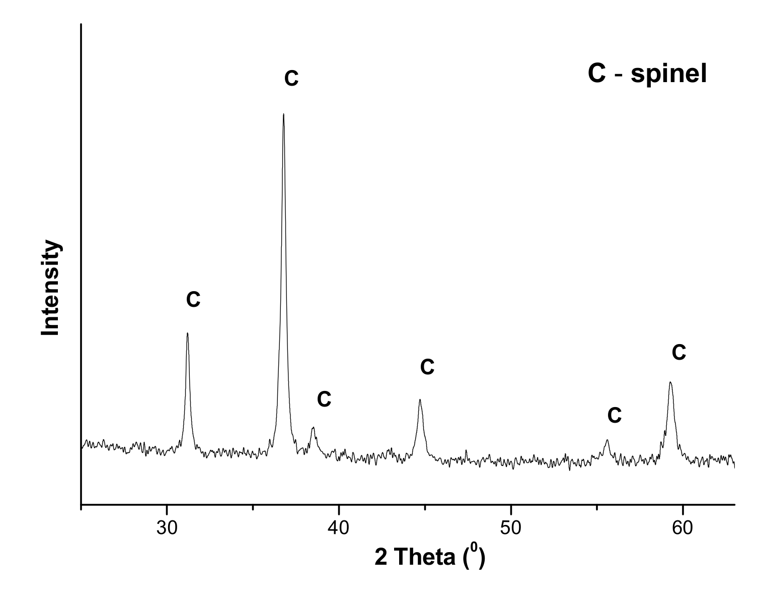
| de-N2O | Cs/Ni0.1Co2.9O4, Cylinders, 3 × 5.2 mm | (−ΔHN2O) = 81 kJ/mol |
Disclaimer/Publisher’s Note: The statements, opinions and data contained in all publications are solely those of the individual author(s) and contributor(s) and not of MDPI and/or the editor(s). MDPI and/or the editor(s) disclaim responsibility for any injury to people or property resulting from any ideas, methods, instructions or products referred to in the content. |
© 2023 by the authors. Licensee MDPI, Basel, Switzerland. This article is an open access article distributed under the terms and conditions of the Creative Commons Attribution (CC BY) license (https://creativecommons.org/licenses/by/4.0/).
Share and Cite
Vernikovskaya, N.; Ivanova, Y.; Sheboltasov, A.; Chumachenko, V.; Isupova, L. Modeling of a Two-Bed Reactor for Low-Temperature Removal of Nitrogen Oxides in Nitric Acid Production. Catalysts 2023, 13, 535. https://doi.org/10.3390/catal13030535
Vernikovskaya N, Ivanova Y, Sheboltasov A, Chumachenko V, Isupova L. Modeling of a Two-Bed Reactor for Low-Temperature Removal of Nitrogen Oxides in Nitric Acid Production. Catalysts. 2023; 13(3):535. https://doi.org/10.3390/catal13030535
Chicago/Turabian StyleVernikovskaya, Nadezhda, Yuliya Ivanova, Artem Sheboltasov, Victor Chumachenko, and Lyubov Isupova. 2023. "Modeling of a Two-Bed Reactor for Low-Temperature Removal of Nitrogen Oxides in Nitric Acid Production" Catalysts 13, no. 3: 535. https://doi.org/10.3390/catal13030535