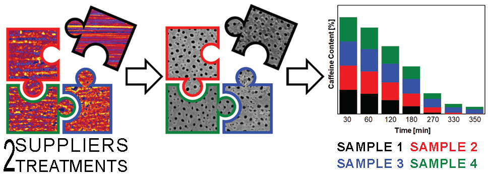
The Influence of a Surface Treatment of Metallic Titanium on the Photocatalytic Properties of TiO2 Nanotubes Grown by Anodic Oxidation


Abstract
:
1. Introduction
2. Results and Discussion
2.1. Characterization of the Titanium Metal Foils
2.2. Anodic Oxidation of the Titanium Foils
2.3. Morphology of the TiO2 Nanotube Arrays
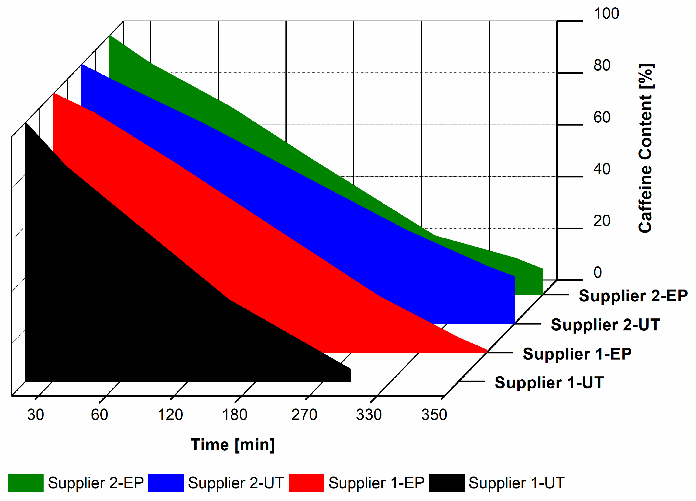
2.4. Photocatalytic Degradation of the Caffeine
3. Materials and Methods
3.1. Electropolishing of Titanium Foils
3.2. Microstructure and Chemical Composition of the Metal Surfaces
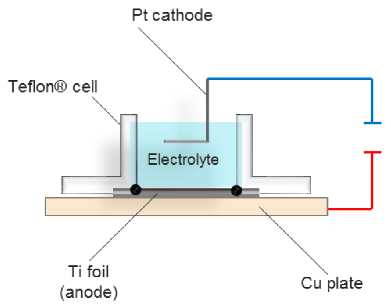
3.3. Anodic Oxidation of Titanium Foils
3.4. Characterization of the TiO2 Nanotube Array
3.5. Photocatalytic Degradation of the Caffeine
4. Conclusions
Supplementary Materials
Author Contributions
Funding
Acknowledgments
Conflicts of Interest
References
- Ibhadon, A.O.; Fitzpatrick, P. Heterogeneous photocatalysis: Recent advances and applications. Catalysts 2013, 3, 189–218. [Google Scholar] [CrossRef] [Green Version]
- Hoffmann, M.R.; Martin, S.T.; Choi, W.; Bahnemann, D.W. Environmental applications of semiconductor photocatalysis. Chem. Rev. 1995, 95, 69–96. [Google Scholar] [CrossRef]
- Kong, M.; Li, Y.; Chen, X.; Tian, T.; Fang, P.; Zheng, F.; Zhao, X. Tuning the relative concentration ratio of bulk defects to surface defects in TiO2 nanocrystals leads to high photocatalytic efficiency. J. Am. Chem. Soc. 2011, 133, 16414–16417. [Google Scholar] [CrossRef] [PubMed]
- Ge, M.; Li, Q.; Cao, C.; Huang, J.; Li, S.; Zhang, S.; Chen, Z.; Zhang, K.; Al-Deyab, S.S.; Lai, Y.; et al. One-dimensional TiO2 nanotube photocatalysts for solar water splitting. Adv. Sci. 2017, 4, 1–31. [Google Scholar] [CrossRef]
- Yu, J.; Low, J.; Xiao, W.; Zhou, P.; Jaroniec, M. Enhanced photocatalytic CO2-Reduction activity of anatase TiO2 by Coexposed {001} and {101} facets. J. Am. Chem. Soc. 2014, 136, 8839–8842. [Google Scholar] [CrossRef]
- Bai, S.; Wang, L.; Li, Z.; Xiong, Y. Facet-engineered surface and interface design of photocatalytic materials. Adv. Sci. 2017, 4, 1–26. [Google Scholar] [CrossRef]
- Roy, P.; Berger, S.; Schmuki, P. TiO2 nanotubes: Synthesis and applications. Angew. Chemi. Int. Ed. 2011, 50, 2904–2939. [Google Scholar] [CrossRef]
- Ou, H.H.; Lo, S.L. Review of titania nanotubes synthesized via the hydrothermal treatment: Fabrication, modification, and application. Sep. Purif. Technol. 2007, 58, 179–191. [Google Scholar] [CrossRef]
- Zhang, J.; Xiao, X.; Nan, J. Hydrothermal-hydrolysis synthesis and photocatalytic properties of nano-TiO2 with an adjustable crystalline structure. J. Hazard. Mater. 2010, 176, 617–622. [Google Scholar] [CrossRef]
- Gong, D.; Grimes, C.A.; Varghese, O.K.; Hu, W.; Singh, R.S.; Chen, Z.; Dickey, E.C. Titanium oxide nanotube arrays prepared by anodic oxidation. J. Mater. Res. 2001, 16, 3331–3334. [Google Scholar] [CrossRef] [Green Version]
- Maiyalagan, T.; Viswanathan, B.; Varadaraju, U.V. Fabrication and characterization of uniform TiO2 nanotube arrays by sol-gel template method. Bull. Mater. Sci. 2006, 29, 705–708. [Google Scholar]
- Zhou, X.; Liu, N.; Schmuki, P. Photocatalysis with TiO2 nanotubes: “Colorful” Reactivity and designing site-specific photocatalytic centers into TiO2 nanotubes. ACS. Catal. 2017, 7, 3210–3235. [Google Scholar] [CrossRef] [Green Version]
- Tao, J.; Zhao, J.; Tang, C.; Kang, Y.; Li, Y. Mechanism study of self-organized TiO2 nanotube arrays by anodization. New J. Chem. 2008, 32, 2164–2168. [Google Scholar] [CrossRef]
- Zhou, X.; Nguyen, N.T.; Özkan, S.; Schmuki, P. Anodic TiO2 nanotube layers: Why does self-organized growth occur—A mini review. Electrochem. Commun. 2014, 46, 157–162. [Google Scholar] [CrossRef] [Green Version]
- Kowalski, D.; Kim, D.; Schmuki, P. TiO2 nanotubes, nanochannels and mesosponge: Self-organized formation and applications. Nano Today 2013, 8, 235–264. [Google Scholar] [CrossRef]
- Boyjoo, Y.; Sun, H.; Liu, J.; Pareek, V.K.; Wang, S. A review on photocatalysis for air treatment: From catalyst development to reactor design. Chem. Eng. J. 2017, 310, 537–559. [Google Scholar] [CrossRef]
- Lu, K.; Tian, Z.; Geldmeier, J.A. Polishing effect on anodic titania nanotube formation. Electrochim. Acta 2011, 56, 6014–6020. [Google Scholar] [CrossRef]
- Hu, N.; Gao, N.; Starink, M.J. The influence of surface roughness and high pressure torsion on the growth of anodic titania nanotubes on pure titanium. Appl. Surf. Sci. 2016, 387, 1010–1020. [Google Scholar] [CrossRef] [Green Version]
- Sopha, H.; Jäger, A.; Knotek, P.; Tesař, K.; Jarosova, M.; Macak, J.M. Self-organized anodic TiO2 nanotube layers: Influence of the Ti substrate on nanotube growth and dimensions. Electrochim. Acta 2016, 190, 744–752. [Google Scholar] [CrossRef]
- Albu, S.P.; Schmuki, P. Influence of anodization parameters on the expansion factor of TiO2 nanotubes. Electrochim. Acta 2013, 91, 90–95. [Google Scholar] [CrossRef]
- Pouilleau, J.; Devilliers, D.; Garrido, F.; Durand-Vidal, S.; Mahé, E. Structure and composition of passive titanium oxide films. Mater. Sci. Eng. B 1997, 47, 235–243. [Google Scholar] [CrossRef]
- Asgari, V.; Noormohammadi, M.; Ramazani, A.; Kashi, M.A. A new approach to electropolishing of pure Ti foil in acidic solution at room temperature for the formation of ordered and long TiO2 nanotube arrays. Corros. Sci. 2018, 136, 38–46. [Google Scholar] [CrossRef]
- Lee, B.G.; Hong, S.Y.; Yoo, J.E.; Choi, J. Electropolishing for the formation of anodic nanotubular TiO2 with uniform length and density. Appl. Surf. Sci. 2011, 257, 7190–7194. [Google Scholar] [CrossRef]
- Macak, J.M.; Jarosova, M.; Jäger, A.; Sopha, H.; Klementová, M. Influence of the Ti microstructure on anodic self-organized TiO2 nanotube layers produced in ethylene glycol electrolytes. Appl. Surf. Sci. 2016, 371, 607–612. [Google Scholar] [CrossRef]
- Zou, J.P.; Wang, R.Z. Debonding phenomenon of TiO2 nanotube film. Trans. Nonferrous Met. Soc. China 2012, 22, 2691–2699. [Google Scholar] [CrossRef]
- Zou, J.P.; Wang, R.Z. Crack initiation, propagation and saturation of TiO2 nanotube film. Trans. Nonferrous Met. Soc. China 2012, 22, 627–633. [Google Scholar] [CrossRef]
- Baek, S.M.; Polyakov, A.V.; Moon, J.H.; Semenova, I.P.; Valiev, R.Z.; Kim, H.S. Effect of surface etching on the tensile behavior of coarse- and ultrafine-grained pure titanium. Mater. Sci. Eng. A 2017, 707, 337–343. [Google Scholar] [CrossRef]
- Jarosz, M.; Kapusta-Kołodziej, J.; Jaskuła, M.; Sulka, G.D. Effect of different polishing methods on anodic titanium dioxide formation. J. Nanomater. 2015, 1–10. [Google Scholar] [CrossRef] [Green Version]
- Konig, U.; Davepon, B. Microstructure of polycrystalline Ti and its microelectrochemical properties by means of electron-backscattering diffraction (EBSD). Electrochim. Acta 2001, 47, 149–160. [Google Scholar] [CrossRef]
- Moulder, J.F.; Stickle, W.F.; Sobol, P.E.; Bomben, K.D. Handbook of X-ray Photoelectron Spectroscopy; Chastain, J., Ed.; Physical Electronics (Perkin-Elmer Corporation): Eden Prairie, MN, USA, 1992; p. 261. [Google Scholar]
- Xie, Z.B.; Blackwood, D.J. Effects of anodization parameters on the formation of titania nanotubes in ethylene glycol. Electrochim. Acta 2010, 56, 905–912. [Google Scholar] [CrossRef]
- Perillo, P.M.; Rodriguez, D.F. Growth control of TiO2 nanotubes in different physical environments. Nanosci. Methods 2012, 1, 194–200. [Google Scholar] [CrossRef]
- Contri Campanelli, L.; Sergio Carvalho Pereira da Silva, P.; Camarinho Oliveira, N.T.; Bolfarini, C. Effect of the modification by titanium dioxide nanotubes with different structures on the fatigue response of Ti grade 2. Mater. Res. 2017, 20, 120–124. [Google Scholar] [CrossRef] [Green Version]
- Tavagnacco, L.; Schnupf, U.; Mason, P.E.; Saboungi, M.-L.; Cesàro, A.; Brady, J.W. Molecular dynamics simulation studies of caffeine aggregation in aqueous solution. J. Phys. Chem. B 2011, 115, 10957–10966. [Google Scholar] [CrossRef] [PubMed] [Green Version]
- Dalmázio, I.; Santos, L.S.; Lopes, R.P.; Eberlin, M.N.; Augusti, R. Advanced oxidation of caffeine in water: On-line and real-time monitoring by electrospray ionization mass spectrometry. Environ. Sci. Technol. 2005, 39, 5982–5988. [Google Scholar] [CrossRef]
- Telo, J.P.; Vieira, A.J.S.C. Mechanism of free radical oxidation of caffeine in aqueous solution. J. Chem. Soc. Perkin. Trans. 1997, 2, 1755–1757. [Google Scholar] [CrossRef]
- Krivec, M.; Žagar, K.; Suhadolnik, L.; Čeh, M.; Dražić, G. Highly efficient TiO2-based microreactor for photocatalytic applications. ACS. Appl. Mater. Interfaces 2013, 5, 9088–9094. [Google Scholar] [CrossRef]


| Untreated Samples | Electropolished Samples | |
|---|---|---|
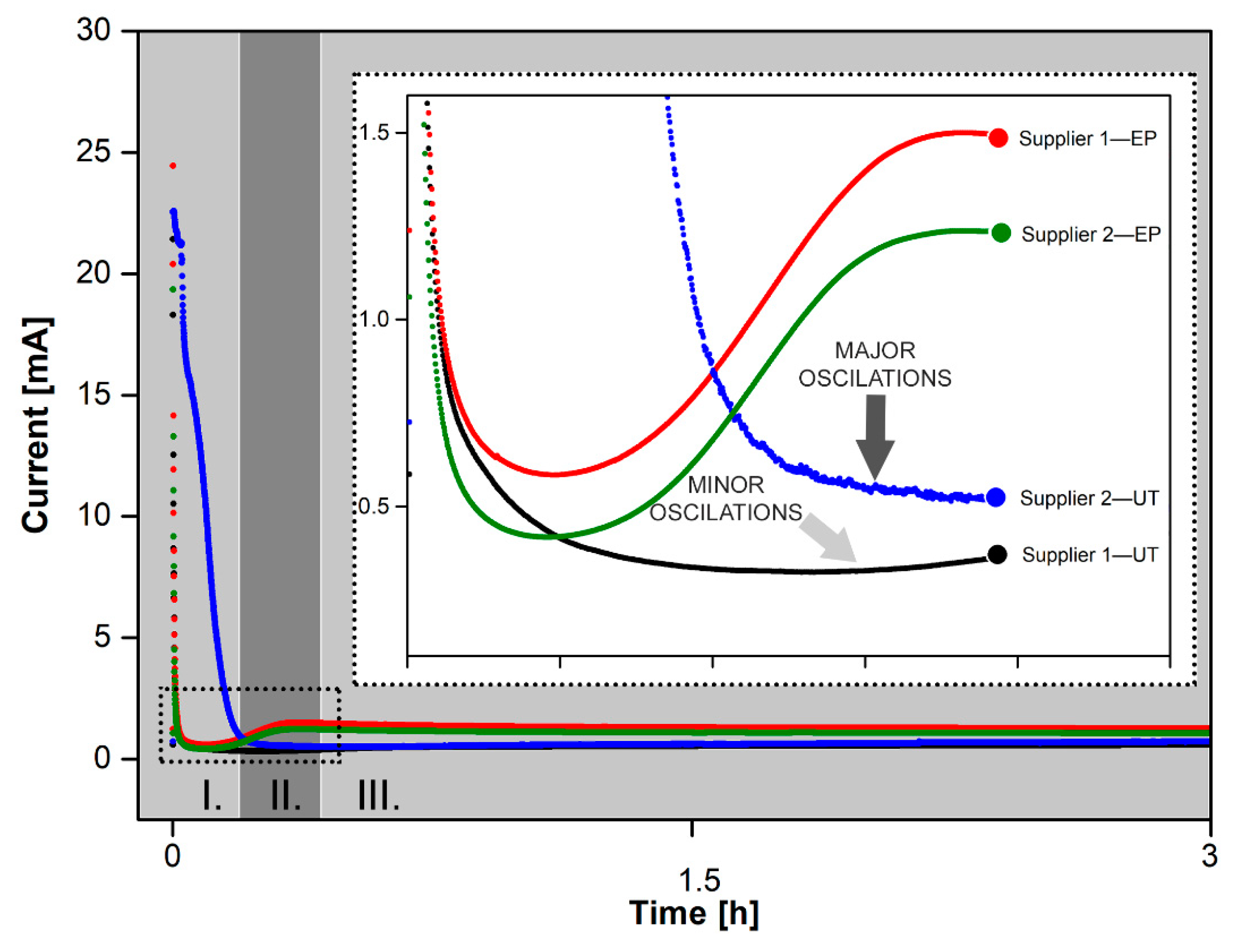
| Shape of the anodization curve |
| A typical 3-step anodization curve corresponding to the 3 phases of the nanotube’s formation process: compact oxide formation, initial porous structure formation, and nanotube growth. |
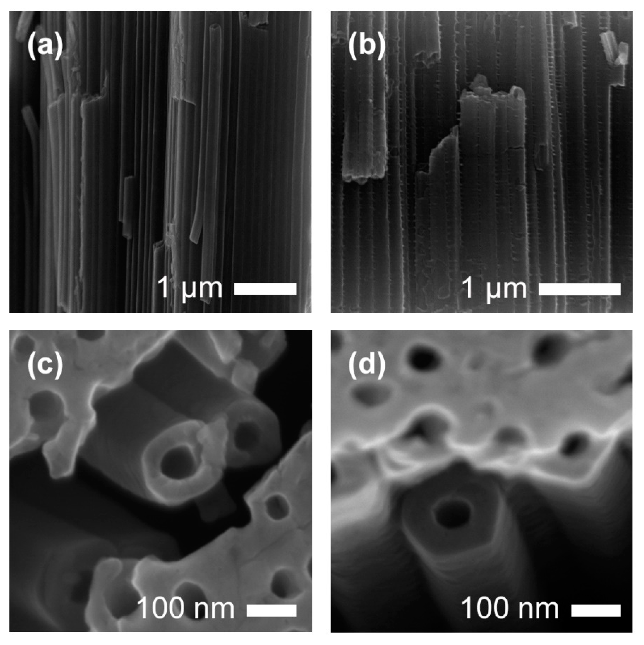
| Explanation: electropolishing decreased the thickness of the starting compact oxide layer, which resulted in the faster formation of etching pits and nanotubes and an increase of current for EP samples can be seen. In case of the untreated titanium foil from Supplier 2 larger undulations and the deep pits present on the titanium foil’s surface caused prolonged generation of the passive oxide layer and the formation of bubbles during the anodization which influenced the appearance of the anodized surface. The current oscillations are due to the repeated dissolution—formation of oxide layer. In contrast, the nanotubes that are grown on the electropolished titanium foil are round with smooth and thinner nanotube walls (Figure 5, Figures S4 and S5). | ||
| Steady-state current | Less than 1 mA. | More than 1 mA. |
| Explanation: a thicker oxide layer is formed at the beginning of the anodization of untreated samples with present impurities and surface defects. This thick oxide layer slows down the migration of the fluoride ions from the electrolyte, resulting in lower currents during the anodic oxidation. The smaller thickness of the compact oxide layer in EP samples caused a higher current density which promoted the growth of longer nanotubes. | ||
| Nanotubes’ shape | A hexagonal shape and ripples along the nanotube wall (Figure 5 and Figure S4). | Round with smooth and thinner nanotube walls (see Figure 5 and Figure S4). |
| Explanation: ripples across the nanotube wall are due to the small periodic current oscillations during anodization. | ||
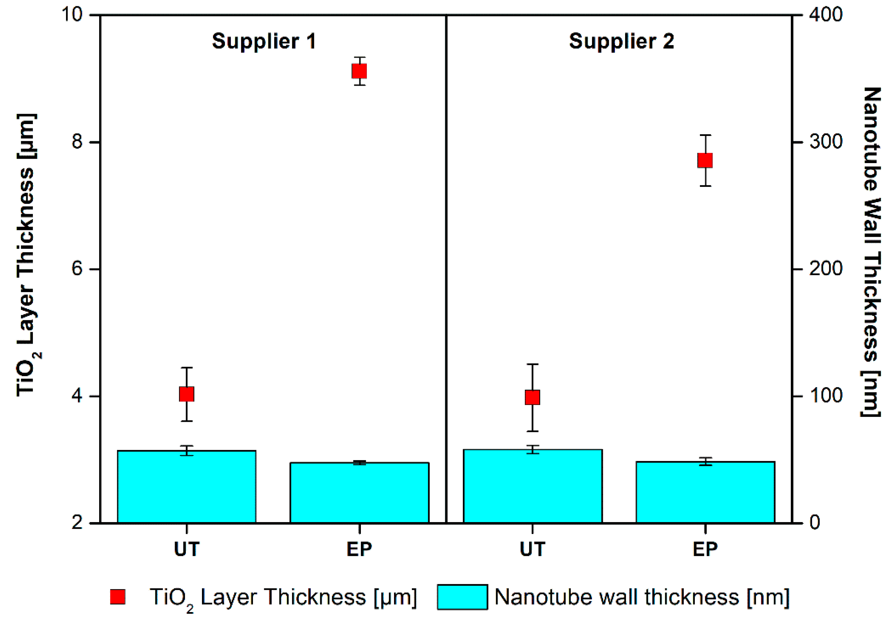
| Nanotubes’ length | Shorter (4 μm). | Longer (8 μm). |
| Explanation: the growth of longer nanotubes was promoted by higher current density in case of electropolished samples. In case of untreated samples, a thinner layer of nanotubes formed under the thicker layer of the upper oxide. | ||
| Supplier 1—UT | Supplier 1—EP | Supplier 2—UT | Supplier 2—EP | |
|---|---|---|---|---|
| Pore Density [%] | 9.7 ± 0.6 | 12.7 ± 3.7 | 5.8 ± 2.9 | 10.9 ± 0.8 |
| Cracked Area [%] | 1.8 ± 0.2 | 4.6 ± 1.6 | 1.0 ± 0.3 | 2.5 ± 0.5 |
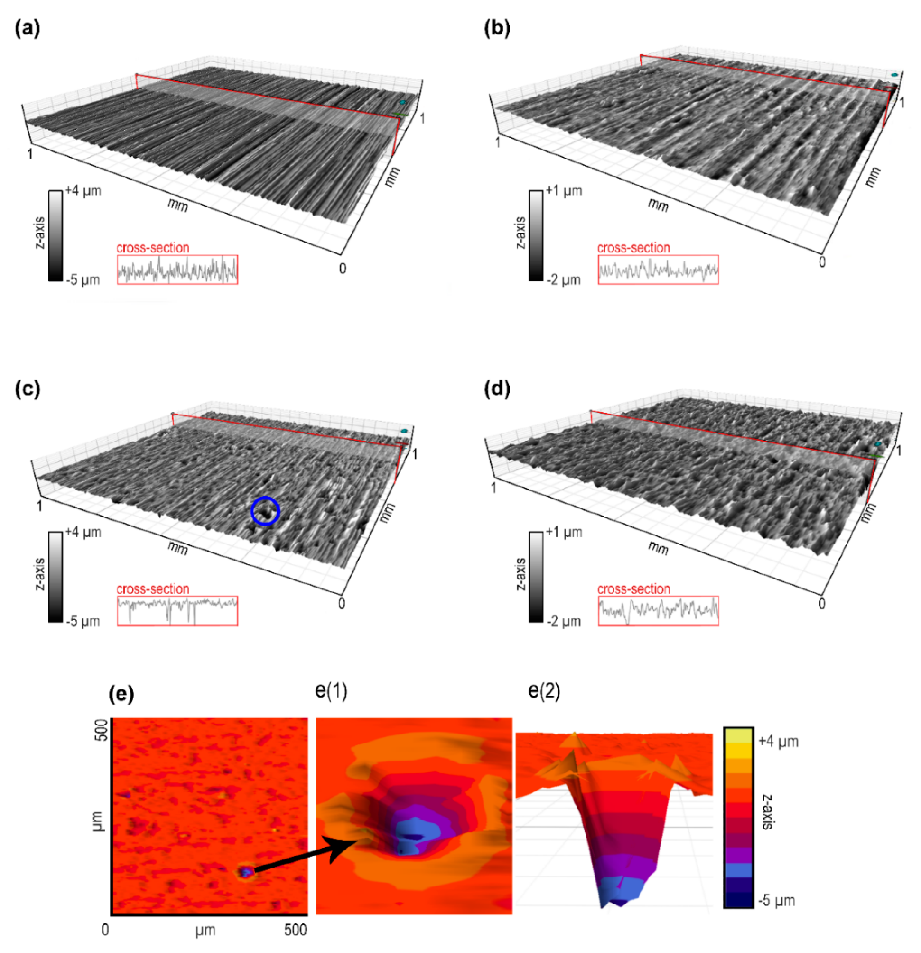
| Average roughness [µm] | 0.187 | 0.108 | 0.632 | 0.136 |
| [wt %] | Ti | Fe | C | N | H | O |
|---|---|---|---|---|---|---|
| Supplier 1 | 99.850 | 0.05 | 0.012 | 0.005 | 0.003 | 0.08 |
| Supplier 2 | 99.663 | 0.15 | 0.02 | 0.012 | 0.005 | 0.15 |
© 2020 by the authors. Licensee MDPI, Basel, Switzerland. This article is an open access article distributed under the terms and conditions of the Creative Commons Attribution (CC BY) license (http://creativecommons.org/licenses/by/4.0/).
Share and Cite
Marinko, Ž.; Suhadolnik, L.; Samardžija, Z.; Kovač, J.; Čeh, M. The Influence of a Surface Treatment of Metallic Titanium on the Photocatalytic Properties of TiO2 Nanotubes Grown by Anodic Oxidation. Catalysts 2020, 10, 803. https://doi.org/10.3390/catal10070803
Marinko Ž, Suhadolnik L, Samardžija Z, Kovač J, Čeh M. The Influence of a Surface Treatment of Metallic Titanium on the Photocatalytic Properties of TiO2 Nanotubes Grown by Anodic Oxidation. Catalysts. 2020; 10(7):803. https://doi.org/10.3390/catal10070803
Chicago/Turabian StyleMarinko, Živa, Luka Suhadolnik, Zoran Samardžija, Janez Kovač, and Miran Čeh. 2020. "The Influence of a Surface Treatment of Metallic Titanium on the Photocatalytic Properties of TiO2 Nanotubes Grown by Anodic Oxidation" Catalysts 10, no. 7: 803. https://doi.org/10.3390/catal10070803