
Microclimate of Air Cavities in Ventilated Roof and Façade Systems in Nordic Climates


Department of Civil and Environmental Engineering, Norwegian University of Science and Technology, 7491 Trondheim, Norway
*
Author to whom correspondence should be addressed.
Buildings 2022, 12(5), 683; https://doi.org/10.3390/buildings12050683
Submission received: 23 March 2022
/
Revised: 6 May 2022
/
Accepted: 16 May 2022
/
Published: 19 May 2022
(This article belongs to the Special Issue Assessment, Diagnosis and Service Life Prediction)
Abstract
:Accurate values for the climatic conditions in an air cavity, hereby called the microclimate, are crucial when calculating and simulating the performance of a ventilated roof and façade system. The climatic stress of its components and their mould and rot potential influence the long-term durability of the roof or façade. A scoping study is conducted to gain an overview on research and the scientific literature on the microclimate of air cavities in ventilated roofing and claddings in Nordic climates. From the body of the research literature, 21 scientific works were of particular interest, and their findings are summarized. The review shows that only a limited number of studies discuss the microclimate of air cavities. Roofs are discussed to a greater and more varied degree compared to façades and air cavities behind solar panels. However, the results cannot be compared and validated against each other to generally describe the microclimate of air cavities, as the surveyed papers approach the subject differently. This knowledge gap indicates that calculations and simulations can be performed without knowing whether the results represent reality. If the structure of ventilated roof and façade systems are only designed based on experience, it can be difficult to be proactive and adapt to future climate changes. Further studies are needed to determine the relation between the exterior climate and the air cavity microclimate, so that future climate predictions can be used to simulate the long-term performance of ventilated roof and façade systems.
1. Introduction
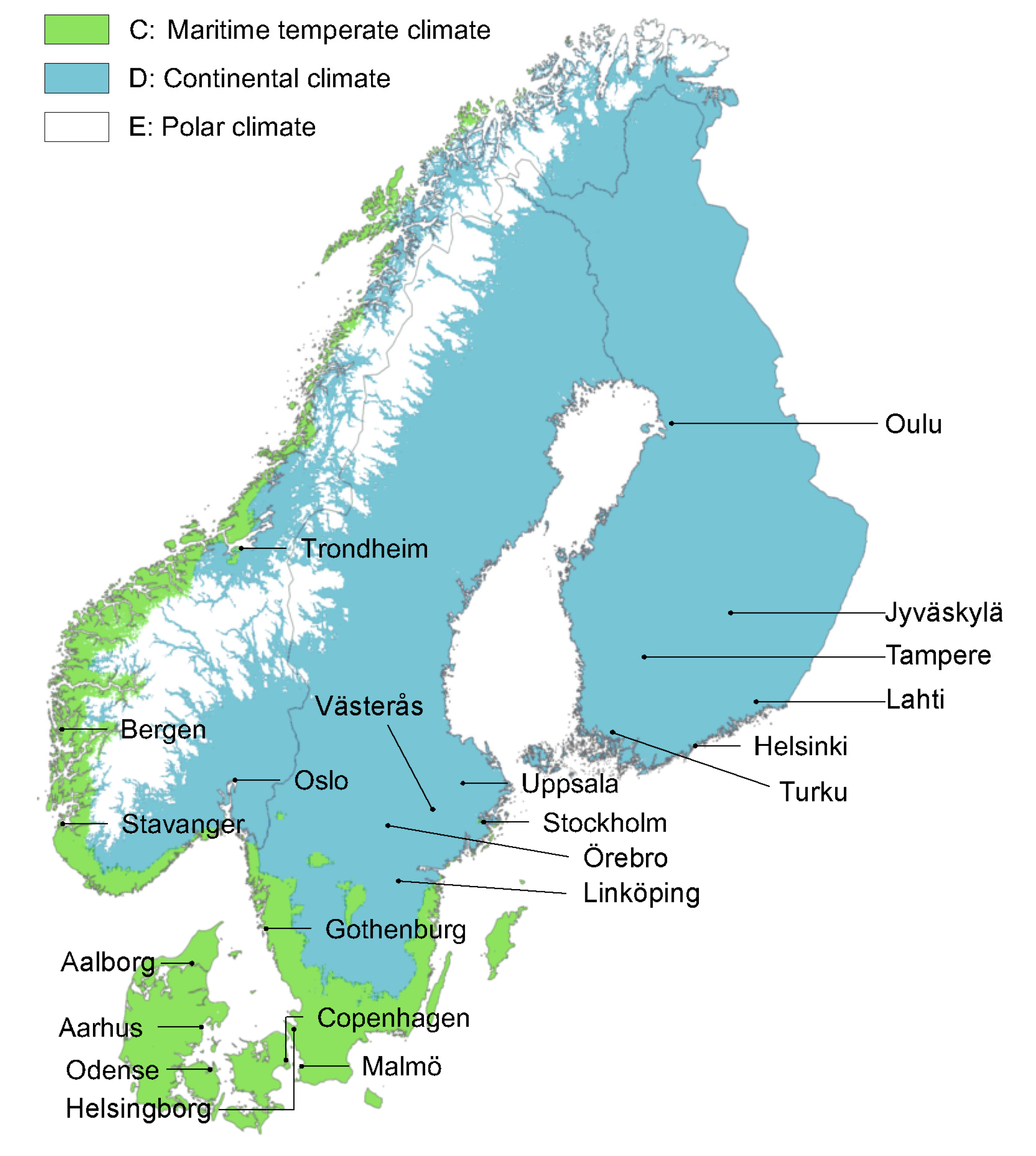
The climate screen of a building mainly consists of its outer walls and roof. Its primary function is to create a shelter against weather exposure. The type and severity of this exposure depends on the geographical location of the building and local conditions specific to its site. In a Nordic climate, the weather will involve strong winds, precipitation, snow loads, great temperature fluctuations, and freeze–thaw cycles [1]. The climate is expected to become more severe in coming years. The temperature and annual precipitation will increase, and extreme precipitation events will become more intense and more common [2]. Climate change of this type will affect material durability, due to an increase in conditions where wood materials will be at risk of deterioration due to biological growth [3]. Among other reasons, the reduction in the number and duration of frost periods is particularly unfortunate, as the growth of mould and fungi will be drastically impeded during and after a frost period [4,5]. The climate zones of the Nordic countries are illustrated in Figure 1.
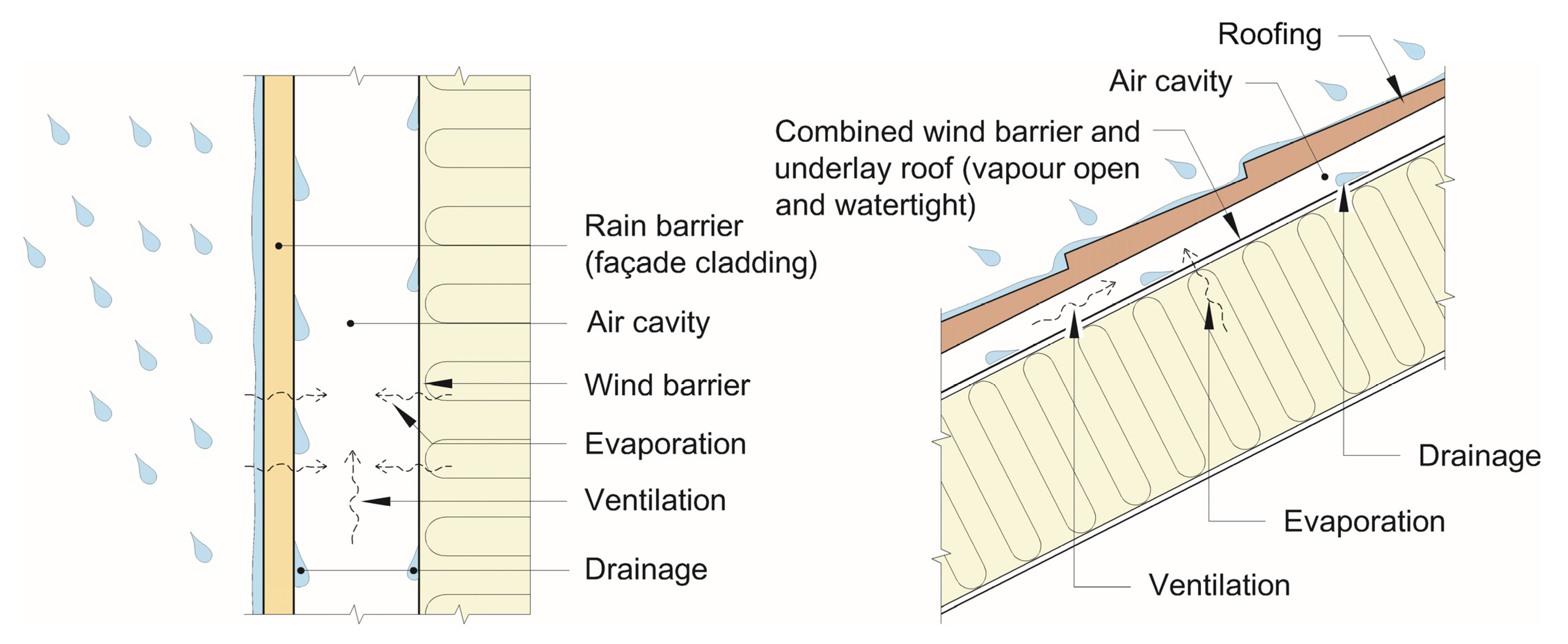
Specific climatic challenges in the Nordic climate include wind-driven rain, freeze–thaw cycles, strong winds, frost, low annual average temperatures, and snow loads, often in frequently varying combinations. Especially in coastal areas, the weather can change rapidly and vary greatly over short periods. To adapt to the varied Nordic climate, facades and sloped roofs are usually built according to a principle of two-stage weatherproofing (“totrinnstetning” in Norwegian) [7]. A universally accepted English translation of this term has not been identified, but the authors are aware that the terms “two-step” or “two-layer” weatherproofing have also been in use, as well as “two-stage tightening” or “two-stage sealing/seals”. The term “two-stage weatherproofing” is preferred in this article as multiple material layers may be involved in the assembly, and the terms “tightening” or “sealing” are direct, but erroneous, translations of the Norwegian term. A roof or façade built according to this principle consists of a rain screen (cladding) and a vapour-open wind barrier layer, separated by an air cavity for drainage and ventilation. The air cavity ensures that precipitation does not leak into the building envelope, and that any moisture in the building envelope is allowed to dry. Note that the air cavity is ventilated to the exterior climate to remove moisture, as opposed to systems such as Trombe walls that are ventilated to the building’s interior for purposes of indoor ventilation [8,9]. For roofs, the ventilated air cavity also prevents heat flows from the building interior from melting snow piled up on the roof tiles, reducing the risk of ice formation. The principle of two-stage weatherproofing is illustrated in Figure 2.
The principle of two-stage weatherproofing has been shown to create robust roofs and façades [7], but climate change might alter its performance. Norwegian statistics show that the share of process-induced building defects caused by precipitation have increased from 24% for the period 1993–2002 to 42% for the period 2017–2020 [12]. Insufficient ventilation and/or drainage of the air cavity is often the main reason why precipitation causes defects in a ventilated façade. Although flaws of the ventilation cavity are usually caused by errors in design or execution that deviate from good moisture safety practices, defects have also been reported in façades built in a way traditionally considered sound [13]. More humid weather with more precipitation and shorter frost periods causes reports of moisture damages hitherto unseen. Wooden battens rot while the cladding remains intact. In a new climate, existing knowledge of moisture-safe design seems to not apply anymore.
Being able to predict service life and making sound material choices for the building envelope is a central part of the building physical design of a building. Service life prediction is conducted using accelerated artificial ageing experiments [14], numerical simulations [15], and knowledge gathering [16,17]. Traditionally, assessments of durability are conducted using the exterior climate as an input parameter. Assessments of accelerated artificial ageing methods show that the determination of precise boundary conditions is a challenge even for façades with only single-stage weatherproofing [18]. Assessing the durability of materials exposed to the microclimate of the air cavity will likewise require in-depth understanding of the climatic boundary conditions. The microclimate of the air cavity will not necessarily correlate directly with the exterior climate [19]. The term “microclimate” is defined as a set of climatic conditions in a limited area, which may differ from those of the surrounding area [20]. New experiences and observed defects suggest a need for better knowledge of climatic conditions in the air cavity to accurately assess the durability of battens, wind barriers, and wind barrier tape. Relevant microclimate parameters for the air cavity may include temperature, relative humidity, air pressure, water intrusion, and air flow characteristics, and how these parameters all behave in relation to those of the exterior climate. This knowledge will be useful when selecting the methodology for accelerated artificial ageing and for numerical simulations of mould/rot risk throughout the lifetime of buildings in Nordic climates.
The purpose of this study is to map the current body of knowledge regarding the long-term microclimate of the air cavity in a roof or wall façade following the two-stage principle for weatherproofing. To address this general issue, the following research questions are investigated:
- To what degree are the climatic conditions of the air cavity of two-stage weatherproofed façades addressed in the research literature?
- Which climatic conditions can be expected in the air cavity of a two-stage weatherproofed façade?
- What are the most important knowledge gaps concerning the climatic conditions of air cavities?
To answer these research questions, a systematic review of the research literature was conducted, using different library databases. Note that there appears to be some disagreement on the nomenclature of the term “air cavity”, with many sources using the term “air gap” instead. This article consistently uses the term “air cavity”, even when reporting on literature using “air gap” in the original text, provided that the cavity in question is ventilated at the top and bottom (an “inlet” and “outlet” opening).
Some limitations to the study are acknowledged: A considerable portion of the literature originates from Norway. This is not unexpected, as the principle of two-stage weatherproofing originates from the Norwegian Building Research Institute (later incorporated into SINTEF) [21,22,23], where research and development of the principle continues today. Other northern European countries, as well as Canada and the United States, have also adopted the construction principle to various degrees. However, in Canada, the main function of the air cavity appears to be drainage, and air cavities are built considerably narrower than in Nordic countries—as narrow as 1 mm [24,25]. For this reason, research from North America was excluded from the main part of this study. Research on air cavities was also identified from Central Europe, but this was also excluded due to the climate being different from Nordic countries. The warmer Central European climate leads to different considerations to be taken when assessing durability and service life. Nevertheless, relevant studies from countries beyond the Nordics are discussed in brief at the end of the Results chapter.
2. Methodology
2.1. Scoping Studies
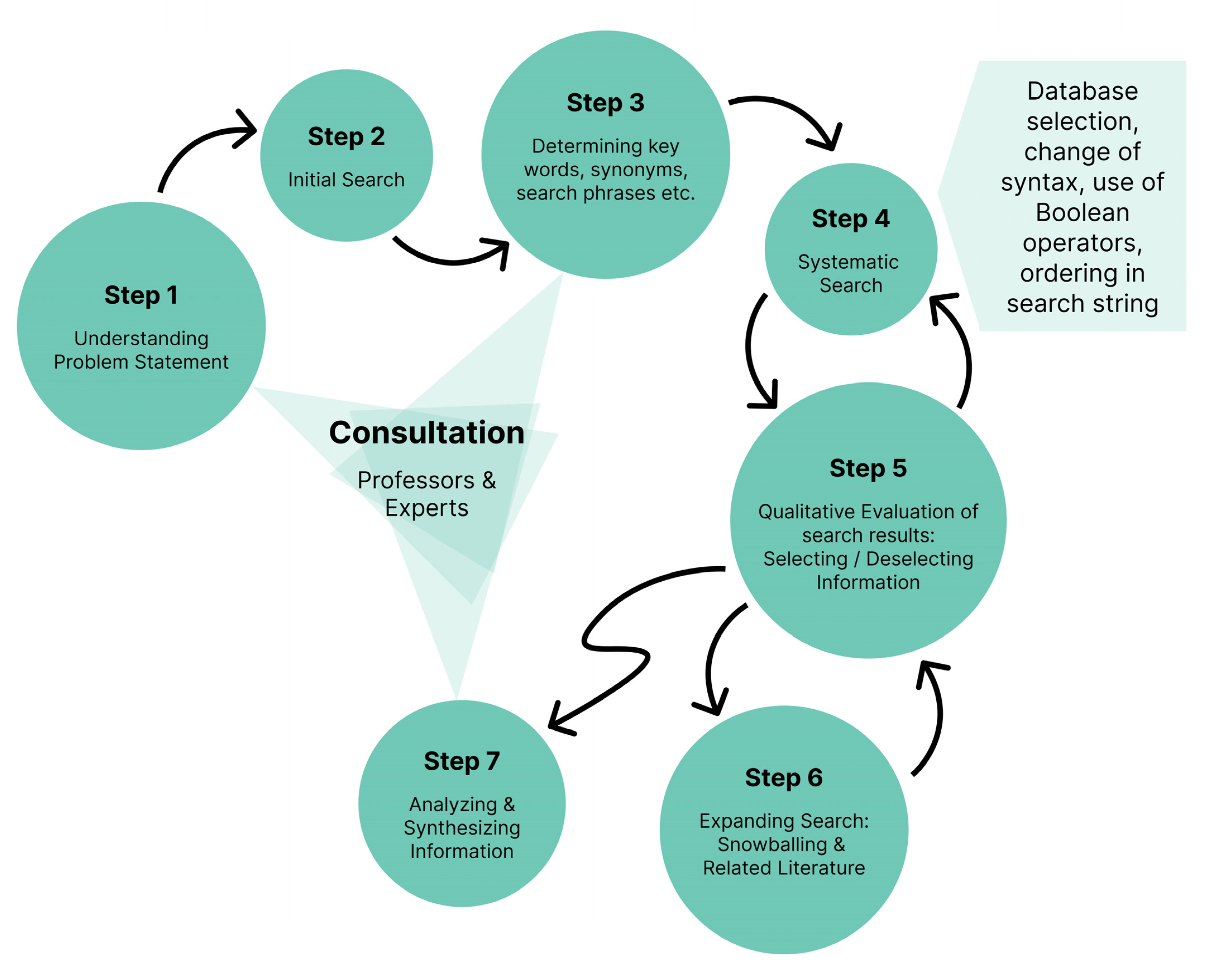
To investigate the current body of knowledge on the microclimate of air cavities, a scoping study was conducted. Scoping studies are used to rapidly map the key terms and concepts within a specific area of research. The framework developed by Arksey and O’Malley [26] was used to guide the literature search through the following five stages:
- Identifying the research questions;
- Identifying relevant studies;
- Study selection;
- Charting the data;
- Collating, summarizing, and reporting the results.
2.2. Literature Search Parameters
The search was conducted through the following literature databases: Scopus, ScienceDirect, Google Scholar, and Web of Science. For an overview of the search terms and search strings that were employed, see the Supplementary File to this article. Filters in the search databases were used to limit the results to scientific articles in English. To further ensure that results were relevant to Nordic climates, the selection of articles was limited to articles originating from Denmark, Finland, Iceland, Ireland, Norway, Sweden, and the United Kingdom. This selection was made to limit the relevance to a Nordic climate, with its associated climatic parameters such as the frequent combination of precipitation and wind, freeze–thaw cycles, frost, and low annual average temperatures, as opposed to cold climates in general which may include high-altitude locations in warmer countries or entirely polar climates.
After a list of relevant articles was found through the database search, citation chaining, or “snowballing” [29], was used to find further relevant studies that were not found in the database search. Search results (Step 5 in Figure 3) were reviewed by assessing the titles of each study. For articles that seemed relevant, abstracts were thoroughly read, and if they appeared to match the research questions, they were included for further assessment of relevance. The search procedure thus resulted in a list of 70 relevant articles, of which 54 were discarded from the final study, for one or more of the following reasons:
- The article did not discuss the microclimate of air cavities (e.g., [30]).
- A microclimate was discussed, but not in relation to a ventilated façade (e.g., [31]).
- The research design of the article did not contain an air cavity, instead focusing on the properties of materials such as insulation or the cladding itself (e.g., [32]).
- The article only considered masonry structures (e.g., [35]).
- Review articles of studies that chiefly contained studies from other climates or countries (e.g., [36]).
Since articles from Norwegian universities constituted a large part of the relevant literature, an additional search was conducted in the Norwegian library database to find M.Sc. theses or other reports that could possibly contain relevant information. This additional search identified five theses containing relevant works of research, primarily published in Norwegian.
3. Literature Review Results
3.1. General Overview of the Literature
The literature search identified 16 scientific articles and 5 M.Sc. theses that discuss the microclimate of ventilated façade and roof cavities specifically in a Nordic climate context. The review includes articles focusing on field studies, laboratory studies, computer simulations, and/or calculations. Of the 21 works of research, 6 focus on façades, 10 focus on sloped roofs, 3 concern roofs and/or façades with integrated photovoltaics, and 2 focus on both façades and roofs. A further 11 studies from outside the Nordic climate were selected to provide a brief overview of relevant research internationally, and to take in some perspectives that were not discussed by the Nordic articles. However, the limits to their applicability in a Nordic context must be noted.
The relevant research originated from Norway (Norwegian University of Science and Technology and SINTEF (formerly Selskapet for Industriell og Teknisk Forskning) in Trondheim), Sweden (Gävle University College, Kungliga Tekniska Högskulan in Stockholm, Lund University, and Chalmers University of Technology in Gothenburg), and Finland (Aalto University near Helsinki). Relevant studies were sought, but not found, from Denmark, Iceland, Ireland, and the United Kingdom, whose climates are similar.
Table 1 presents an overview of the individual studies identified in the literature review. Some studies resulted in (or contributed to) multiple publications, as shown in the “References” column. The investigated climate parameters of each study are also listed, as well as the duration of measurements (if applicable). Note that not all of the studies measured the parameters the same way or presented the measurements directly.
3.2. Façades
Falk and Sandin [38] described field studies measuring air velocities and temperatures in south-facing, vented, and ventilated façades using different batten configurations. The research period spanned 2400 h between the beginning of October and the middle of February. A single sensor was moved periodically between the three test specimens. The results were compared to a simulation model. The studies found an average absolute air velocity in the cavity of 0.195 m/s and an average driving force of 0.3–0.5 Pa. According to calculations, the air change rate for the cavity was 230-310 ACH (air change rate per hour). The maximum rate was 2–3 times higher than the average rate, primarily driven by thermal buoyancy. The results showed a clear correlation between average cavity temperature and flow characteristics, where the temperature increased if the flow resistance was increased.
A further study by Falk and Sandin [39] explored the connection between air cavity design, air change rate, and ventilation drying processes. Calculations and mathematical models were employed and compared to field studies from the previous article from Università di Napoli Federico II. The results showed that the model used to calculate ACH yielded values that agreed with field measurements. The calculations of drying rates showed that the evaporation of moisture to the air cavity varied greatly between the different air cavity designs, but the variations tended to even out over time. The measurements also showed that a favourable exterior climate and the colour of the façade cladding had a greater impact than the design of the air cavity, and that a cavity width of 40 mm yielded 20–25 times more drying potential than a cavity 5 mm wide.
A third study in this series [40] presented a method to predict ACH in an air cavity. Mathematical models were used alongside climate data and validated using field measurements from [38]. The results showed that the calculated ACH largely fit the measured values from the field studies, even reflecting hourly variations. The model still was shown to be slightly lacking for daytime conditions. Significant hourly deviations were observed during daytime hours, showing thermal buoyancy to be weak compared to wind pressures.
Uvsløkk [41] presented information on how wind affects the air pressure in an air cavity. Field experiments, laboratory experiments, and calculations were conducted. The results indicated that the geometry of the air cavity and the details near the cavity openings greatly affected the pressure gradients in the air cavity and that the calculation methods were less suitable for complex cavity geometries. The article concluded that for most locations in Norway, it will be sufficient to use a reference wind velocity of 10 m/s, 10 m above the ground, for calculations spanning the heating season.
Nore [42] sought to increase the scientific knowledge of the performance of wooden claddings through conducting field studies. Sensors were mounted on the inside and outside of the wooden cladding on a test building in Trondheim, measuring the exterior climate, the relative humidity in the air cavity, and the moisture content of the wooden cladding. Measurements ran across four years between 2004 and 2007. The measurements showed that the cladding’s hygrothermal response depended greatly on the orientation of the façade, largely due to different exposure to solar radiation, wind, and wind-driven rain. Further, the results showed that an air cavity was necessary, but that an air cavity opening of 23 mm did not significantly improve the drying potential of a west-facing façade compared to a smaller cavity opening of 4 mm. The surface treatment of the cladding affected the response to climate exposure, where untreated wood responded faster to variations compared to surface-treated wood, giving larger fluctuations in the moisture content of the cladding. Changes in the claddings’ moisture content were more correlated with variations in temperature, solar radiation, and wind speed than with variations in precipitation, wind-driven rain, and wind direction.
Nore et al. [43] studied the wind-driven air stream in a 23 mm air cavity in a ventilated cladding using RANS CFD simulation, a validation study, and a comparison to earlier studies. The validation study showed a margin of error of 25% for cavity air flows with a Reynold’s number (Re) between 1000 and 3500. Simulations with a Re outside these parameters showed an ACH/U10 between 120 and 250 for a high reference wind speed of 10 m/s perpendicular to the façade. The CFD results of cavity air speed and air change rate were compared to those of previous experimental studies, indicating agreement. Local pressure losses were calculated by comparing the results of separate and combined simulations. The pressure loss coefficient for wind perpendicular to the façade was between 4.5 (middle cavities) and 5.7 (edge cavities), and for wind angled at 22.5 degrees, it was between 4.9 and 7.1.
Viljanen et al. [44] evaluated the performance of the air cavity for a highly insulated façade by assessing mould growth potential as a performance criterium and investigating which factors affect this performance. Field studies were conducted on two externally insulated air cavities with a thermal resistance R = 0.18 and 1.57 m2K/W on the exterior side. Measured parameters included absolute humidity, solar radiation, mould growth potential, and the temperature and relative humidity in the air cavity and the exterior air. The results indicated that the average temperature in the winter season was 0–2 °C lower in the air cavity than in the exterior air, but the RH was typically 0–15% lower, depending on the type of wall. The computational analyses showed that the optimal air change rate was 4–40 h−1. Significant mould growth in the air cavity was only possible near the inlet area, where the temperature was the lowest and RH the highest. The analytical model identified that the most influential factors for the hygrothermal conditions in the air cavity were the interior and exterior R values, the ACH of the air cavity, and the vapour resistance of the layers close to the air cavity. Insulation on the exterior side of the air cavity improved the performance of the air cavity, but it was shown that reducing the size of the inlet can be beneficial. Exterior R values should not exceed R = 0.35–0.5 m2K/W to maintain solar-radiation-driven drying and to prevent mould growth during the summer season.
Overall, it may be seen that the research regarding the microclimate of façade air cavities primarily concerns air flows by buoyancy and responses to wind, while parameters such as moisture and temperature remain little studied. Viljanen’s work [44] is a welcome exception, but unfortunately, the measurements were conducted on an unconventional wall assembly that cannot be directly compared to the remainder of the studies.
3.3. Roofs
Gullbrekken et al. [45] presented calculations to determine pressure losses at the inlet (eave) opening and inside the air cavity, consisting of friction losses and passing of tile battens. The study consisted of a large-scale laboratory experiment and a numerical analysis using the COMSOL software. The results showed that the pressure loss coefficient of the airstream was greatly dependent on the shape of the tile battens (aligned perpendicular to the air flow through the air cavity). Tile battens with rounded edges were found to incur a pressure loss coefficient 40% lower than battens with right-angled edges. Additionally, the results indicated that a classic eave design gave a lower pressure loss coefficient than modern eave design. Installing a bug net at the openings of the air cavity doubled the pressure loss coefficient. The calculations as well as laboratory and field studies were further described in an M.Sc. thesis by Hansen [46]. Hansen noted that the air cavity width should be increased by increasing the height of the longitudinal battens rather than the cross battens, to reduce pressure losses of the cavity air flow. Another M.Sc. thesis that contributed to the results of [44] is that of Eggen and Røer [47], who built upon the study by Hansen. The two theses disagree slightly on whether it is more advantageous to ventilate the roof cavity through openings in the eaves or behind the roof gutter. The disagreement might be explained by the different placement of sensors in the two experiments.
Bunkholt et al. [48] investigated, through a laboratory study, how the air flow through a ventilated roof cavity is affected by temperature and air cavity design. Measurements indicated that the air cavity temperature and flow conditions were affected by the cavity width as well as the roof angle. The temperature decreased and air flow rate increased with higher roof angles and larger cavity widths. Increasing the cavity width only increased the air temperature up to a certain point. The optimal cavity width was found to be 48 mm. Increasing the cavity width from 23 mm to 70 mm reduced thermal buoyancy by two thirds. The results of the study were also presented in a Master thesis [49]. A result reported in the thesis is that thermal buoyancy caused a driving pressure equivalent to a wind speed of 0.4–2 m/s. Thermal buoyancy may thus be the primary driving force of the airflow through the air cavity large portions of the year in Norway.
Säwén et al. [50] presented an analytical model to predict the air flow due to buoyancy in a ventilated roof assembly. The developed Thermal Buoyancy Model was compared to a laboratory study and a numerical calculation by using all three methods to analyse the air flow and thermal conditions in an air cavity using the same test setup and the same Norwegian climate. Results from the laboratory experiment and the numerical simulations quantitatively showed that an increase in the heat loads or the roof inclination increased the air flow rate due to increased driving forces. Increasing the cavity width increased the air volume flow due to decreased air flow resistance. The analytical model underestimated the air volume flow by an average of 20% compared to the laboratory experiment, and overestimated by 3% compared to the numerical calculations, but the trends are similar.
Mundt-Pedersen and Harderup [52] investigated the suitability of a 1D hygrothermal calculation tool in the design phase to prevent and evaluate the risk of mould growth and moisture damage in ventilated roofs. Moisture and temperature sensors were mounted in different positions in the roofs of four residential buildings in Sweden, while similar roof structures were modelled in the WUFI simulation program. The sensors measured temperature and RH over a period of 12–33 consecutive months. Quantitative results from sensors and WUFI were compared to each other and to critical values for mould growth. The results indicated that WUFI can be used as a tool to predict the climatic conditions, but that multiple parameters will affect the results and need to be considered to reliably assess the mould growth potential.
In addition to their evaluations of façades as described in Section 3.3., Viljanen et al. [44] assessed the performance of a roof structure. Field measurements were conducted similarly to what was carried out for façades, insulating the exterior side of a roof air cavity with a thermal resistance value R = 0.13 and 2.13 m2K/W. Calculation analyses showed that the optimal air change rate for the setup was 20 h−1. Significant mould growth in the cavity was only possible near the inlet, where the temperature was lowest and the RH was highest. The analytical model identified the most influential parameters for the hygrothermal conditions in the cavity to be the internal and external R values, the ACH of the cavity airspace, and the vapour permeability of the vapour control layer. Insulating the exterior side of the air cavity was shown to increase the performance of the air cavity. Exterior R values should not exceed 0.7 m2K/W to maintain solar drying and to prevent mould growth in the summer season.
Gullbrekken et al. [53] described the risk of condensation on the interior side of the air cavity and mapped the relation between the air velocity in the cavity and the exterior wind speed. Field measurements were conducted in Norway using sensors to measure surface temperatures, the air temperature in the air cavity, and the air velocity in the cavity for three seasons: spring, summer, and autumn. The temperature below the roofing was shown to be lower than the exterior temperature 51%, 14%, and 56% of the time, respectively, for the three seasons. The measurements indicated a strong correlation between the wind speed and the air flow velocity in the air cavity. The hourly air exchange rate could be estimated as 11 h−1 for periods of low wind speed and 84 h−1 for periods of high wind speeds.
Bunkholt et al. [19] investigated the influence of exterior temperatures on the temperature in the air cavity, what condensation potential results from an air cavity temperature lower than the exterior temperature, and what the consequences of condensation risk can be. Field studies were conducted using sensors to measure surface temperatures, air temperature in the air cavity, and the air volume flow in the air cavity. Measurements were conducted over five periods in Norway between 2016 and 2018: one period each for spring, summer, and autumn, and two periods during winter. The results showed marked periods of air cavity temperatures being lower than the exterior air temperature and positive CPi (condensation potential) values for extended periods, especially during spring and autumn, and in winter periods without snow on the roof. This indicated that the materials in the roof absorbed moisture and regulated the air humidity in the air cavity. Large negative CPi values indicated drying of the roof structure.
Rønningen [54] conducted a field study on air cavities on research buildings in Trondheim, Norway. Solar radiation was measured to cause significantly higher temperatures in the air cavity (up to 35–40 degrees) than the outside air temperature. Near the top of the ventilated roof cavity of a sloped roof, temperatures were lower than outside temperatures 42% of the time, compared to 63% at the bottom. For a neighbouring building with a saddle roof, the numbers were 58% and 63% for the south and north side, respectively. Moisture measurements showed that the battens were able to dry quite quickly, going from a moisture level of 37 weight-% to 25% in 38 days.
Tianshu [51] conducted a numerical study of the air flow in air cavities for pitched wooden roofs using computational flow dynamics (CFD). It was found that increasing the width of a cavity from 23 to 48 mm greatly reduced the pressure gradient, friction coefficient, and total loss coefficient. A further increase to 140 mm yielded significantly lower impacts. The shape of the tile battens also greatly influenced the air flow, with a small rounding (r = 4 mm) of the edges reducing the loss coefficient by 20% compared to right-angled battens.
3.4. Building-Integrated Photovoltaics (BIPV)
Sandberg and Mosfegh [55] analysed the air flows and thermal transfer due to thermal buoyancy behind solar panels numerically and experimentally. Laboratory experiments were conducted in Sweden, where thermoelements on the exterior side of the air cavity simulated a solar heating flux of 20–300 W/m2. Numerical simulations were conducted with a uniform thermal flux varying between 20 and 500 W/m2. The results showed agreement between the laboratory experiments and the simulations and indicated that it is advantageous to use high-emissivity materials for surfaces in air cavities. The analysis revealed the importance of thermal radiation exchange for the heat transfer mechanisms between the air cavity walls. For a thermal flux at or above 200 W/m2, almost 30% of the heat was transferred to the otherwise unhated wall through radiation, and from there, it was transferred to the air through convection.
In a further study [56], the same authors investigated governing parameters for air flows generated by the heat transfer between solar panels and air cavities. A laboratory study was conducted, using the variables of inclination angle, the placement of solar panels, and the ratio between air cavity length and width. The results indicate that all the variables greatly influenced the air change ratio and the temperature of the air cavity. The velocity profile was uneven, and the highest airflow velocity did not necessarily occur on the heated side, which indicated a complex airflow pattern. The net effect would be an uneven cooling of the PV module, reducing its electricity generation. The temperature profile showed the highest temperature by the heated wall, the second highest temperature along the opposite wall of the air gap, and the lowest temperature in the middle of the air cavity. The temperature across the entire air gap decreased as the wall/roof angle increased.
In a final study [57], Sandberg and Mosfegh analytically derived expressions for the mass flow rate, air velocity, temperature increase, and location of neutral height (the point where the air pressure in the air cavity is equivalent to the ambient air pressure) in air cavities behind solar panels mounted on vertical façades. The calculations were compared to measured temperature values from previous studies [55,56]. The results indicated a good correlation between analytical expressions and experimental measurements for situations of constrained flow due to the small area of the inlet and/or the outlet compared to the cross-section area of the air cavity. With both ends at the size of the cross-section of the air gap, the agreement was 10–20% but increased at higher wall heights and cavity width ratios. Possible reasons for the discrepancy between the theory and measurements include difficulties with the laboratory measurements and the uncertainty in the many parameters required for a mathematical calculation. Sandberg and Mosfegh’s studies comprise the only identified work that concerns the microclimate behind photovoltaic façade elements, unfortunately making comparisons impossible.
3.5. Notable Studies from Outside Nordic Climates
Some studies were identified that directly address the concerns of the present review but that were not included in the main assessment (Table 1) for various reasons. For the sake of reporting the wider international perspective on the microclimate of ventilated air cavities, some notable studies are recounted in this section.
Bouchair [9] presented a theoretical framework for describing cavity airflows in relation to an interior and exterior climate, using the example of a wall built for solar-driven ventilation in an Algerian climate. While “Nordic” parameters such as frost or wind-driven rain were not considered, the equations described may be used to create numerical models of air behaviour in cavities.
In Vancouver, Canada, Tariku and Iffa [58] performed an experimental study assessing the hygrothermal performance of wood frame systems built with different concepts of air cavities (ventilated, vented, no cavity). The findings included that ventilated façades have a vastly higher air change rate; that temperatures behind the façade boards are lower in the wall without an air cavity during winter days; and that the ventilated cavity sees a higher moisture content in the upper section during the wet winter season. This article was not included in the main study as Canada fell outside the scope of Nordic climates; however, the similar temperature conditions of the study site imply that its conclusions can be relevant, nonetheless.
Also in Canada, John Straube and various co-authors [24,25,59,60] examined the role of air cavities in the drying and ventilation of façades. A cavity width as small as 1 mm was found to be enough to ensure drainage. The openings of air cavities were found to play a significant role in the drying potential, they should be as large and unobstructed as possible to ensure drying. Straube also documented that moisture retained in the cavity air and deposited on surfaces was very challenging to simulate in computer models, highlighting the need for field studies and laboratory measurements.
Defo et al. [61] assessed the moisture performance and durability of brick veneer walls in the face of climate change in Canada. The deposition of moisture by wind-driven rain was found to pose a moisture risk on Canada’s east coast, and it was found that an air cavity should be accompanied by other measures such as roof overhangs to reduce this risk.
Rahiminejad and Khovalyg [62] reviewed the literature on ventilation rates in ventilated air cavities in façades. A theoretical framework and mathematical models of cavity air flows were presented. The reviewed articles relevant to Nordic climates are all included in the present study.
Van Belleghem et al. [63] modelled the air, heat, and moisture transport in ventilated cavity walls in Belgium, comparing a simplified model in WUFI to a more detailed model. The WUFI model was found to overestimate the ventilation effect on drying and subsequently indicate lower moisture levels than was the case. A lesson learned from this study is that the widely commercially used software may not be sufficient to evaluate the moisture risk in air cavities accurately, presenting a challenge to the building designers who may rely upon it for moisture risk assessment.
Also in Belgium, Langmans and Roels [35] compared four measuring techniques for analysing cavity ventilation behind rainscreen cladding systems. The most suitable method depended on the type of cladding: a vented brick veneer façade displayed air change rates two orders of magnitude lower than ventilated siding, and thus required a pressure gauge to accurately measure the air change rates. The study indicated that measurements of air change rates in air cavities behind brick veneer may not be directly comparable to those behind more open façade claddings.
Marinosci et al. [37] investigated, numerically and experimentally, the thermal behaviour of a rainscreen façade in Italy, featuring an air cavity width of 240 mm. The velocity and temperature distribution of the air in the air cavity was measured and modelled. Correlating values between the model and field measurements suggested that the model is suitable for simulating large air cavities. The study, while thoroughly describing air flows and temperature, did not consider moisture.
4. Discussion
4.1. Air Cavities in Research Literature
An observation recorded early in the literature review was that the literature focusing on brick or rendered façades is much more abundant than the literature on ventilated façades. Even within the latter category, more literature focuses on the cladding itself or the structure behind the wind barrier than on the climate within the air cavity. Many of these articles use assumed climate data for the cavity for calculations or simulations, without performing or citing studies that indicate whether they match the actual conditions. If anything, these articles illustrate the need for the microclimate in air cavities to be investigated further.
The relevant literature recounted in this review originates from a quite small number of researchers at a few research institutions in Norway, Sweden, and Finland. In practice, only six independent field studies and two independent laboratory studies were identified within the relevant scope and climate. Several of the studies lack adequate descriptions of research parameters such as the precise design of the structure, or climate data for the research period, which makes it challenging to replicate or validate the results. The studies are also too different to make it feasible to directly compare their results with each other. For instance, the studies from Finland [44] investigated air cavities with insulation on the exterior side, while the solar panel studies from Sweden [55,56,57] applied heat sources to the exterior side. Another observed issue is that the studies did not seek to quantify or describe microclimate parameters in the air cavity over time, with a chief focus instead being to compare the performance of different designs.
Wider international literature has been found that addresses these concerns to a greater degree, describing studies that cover hygrothermal conditions in finer detail with several parameters. However, the studies are of limited applicability, as they do not consider temperatures below 0 °C and rarely cover rain penetration. The deposition of liquid water in general remains challenging to simulate in numerical models. It was reported by Van Belleghem et al. [63] that commonly used simulation software tends to underestimate moisture loads, highlighting a challenge in using computer models to investigate high-moisture environments such as air cavities subject to wind-driven rain.
4.2. Climatic Conditions in the Air Cavity
A common observation across many of the field studies was that the temperature of the air cavity will be colder than the ambient air temperature for significant portions of the year, particularly near the inlet opening of the cavity. This creates potential for condensation and moisture damage. There is insufficient data to quantify the moisture risk due to this effect, as the studies are limited to short measurement periods and limited local climates—effectively, relevant measurements have only been conducted in Trondheim in Norway and Lund in Sweden.
Laboratory studies suggest that thermal buoyancy is a quite weak driving force of cavity airflows when compared to wind pressure [49]. The shape of the tile battens has a surprisingly large influence on the airflow resistance of the air cavity of ventilated roofs, with rounded battens reducing the pressure loss coefficient by 20–40% compared to right-angled battens [53]. This effect was observed through both laboratory and CFD studies [51].
4.3. Knowledge Gaps
This study uncovers certain knowledge gaps regarding the microclimate of ventilated cavities in façades and roofs in Nordic climates. There is a general lack of research into the long-term climatic behaviour of air cavities, and the few available studies are not directly comparable to each other. Little systematic research has been conducted that considers all relevant climatic parameters over time, such as the combination of temperature and moisture (in the cavity materials as well as in the air) and how they vary during all seasons. More studies, carried out in a comparable fashion to existing studies, would help address the limited availability of data. Concrete knowledge gaps that have been identified and should be addressed by future studies include:
- To what degree the temperature and relative humidity of the air cavity and correlate with that of the ambient air in long time series, considering the impact of wind, humidity, and rainwater penetration.
- The impact of precipitation and freeze–thaw cycles and how they affect the durability of materials in the building envelope.
- Determining how the air cavity microclimate can be simulated for long-term simulations using exterior climate data in a Nordic climate.
- Determining and describing the climatic loads that materials in the air cavity must withstand to achieve sufficient durability.
- Validating the accuracy of models of humidity conditions in the air cavity, using field or laboratory measurements.
Knowledge about these issues is required to improve the accuracy of simulations and calculations of the durability of materials in ventilated roof and façade systems, increasing the accuracy and reliability of service life predictions.
5. Conclusions
This study showed that the extent of research into the climatic conditions in air cavities in ventilated building roof and façade systems is limited. There is a general lack of comparable studies and quantitative results. The studies are also geographically limited; even though ventilated façade and roof systems are widespread across northern Europe, research into their operating parameters is mainly conducted in Norway and to a limited degree in Sweden. Roofs have generally received more research attention than façades. The studies show how the microclimate of the air cavity may differ from the exterior climate, with the cavity air temperature often being lower than the exterior air temperature. This creates a risk of mould in the air cavity. Thermal buoyancy is also seen to be a relatively weak driving force of air flow in cavities, while the impact of wind is significant.
The implication of the deficiency of studies is that there is currently no good information to use in assessing the durability and service life of materials in air cavities. Industry experience suggests that the principle of two-stage weatherproofing creates durable façade and roof systems, but new types of defects emerge due to a changing climate. It is currently difficult to predict how to improve designs to address these challenges to material durability, as the climatic loads in air cavities are not well studied.
Future work should aim to gather sensor data from buildings spread across different Nordic climate zones over extended durations of time. The relation between the exterior climate—e.g., as described in climate files for simulations—and the climatic conditions of air cavities must also be investigated further. Sensor data may be compared to climate data to evaluate the correlation between the exterior climate and the cavity microclimate, to determine necessary corrections when using climate data to simulate the conditions of ventilated air cavities. Such simulations are essential in evaluating the risk of rot and mould growth in air cavities, and thus the long-term deterioration of components such as the cladding, battens, and wind barrier.
Supplementary Materials
The following supporting information can be downloaded at: https://www.mdpi.com/article/10.3390/buildings12050683/s1, Table S1: Search Strings.
Author Contributions
Conceptualization, S.B.I. and T.K.; methodology, S.B.I., E.A. and T.K.; formal analysis, S.B.I.; investigation, S.B.I.; writing—original draft preparation, S.B.I. and E.A.; writing—review and editing, S.B.I., E.A. and T.K.; supervision, E.A. and T.K.; funding acquisition, T.K. All authors have read and agreed to the published version of the manuscript.
Funding
This research was funded by the Research Council of Norway, grant number 237859.
Institutional Review Board Statement
Not applicable.
Informed Consent Statement
Not applicable.
Acknowledgments
The work is carried out as part of the research project SFI Klima 2050–Climate adaptation of buildings and infrastructure. The authors would like to extend a thanks to CAD operator Remy Eik at SINTEF.
Conflicts of Interest
The authors declare no conflict of interest.
References
- O’Brien, K.; Sygna, L.; Haugen, J.E. Vulnerable or Resilient? A Multi-Scale Assessment of Climate Impacts and Vulnerability in Norway. Clim. Chang. 2004, 64, 193–225. [Google Scholar] [CrossRef]
- Hanssen-Bauer, I.; Drange, H.; Førland, E.J.; Roald, L.A.; Børsheim, K.Y.; Hisdal, H.; Lawrence, D.; Nesje, A.; Sandven, S.; Sorteberg, A. Klima i Norge 2100-Kunnskapsgrunnlag for Klimatilpasning Oppdatert i 2015; Norwegian Environmental Agency/Norwegian Climate Service Center: Oslo, Norway, 2015. [Google Scholar]
- Lisø, K.R.; Kvande, T. Klimatilpasning Av Bygninger, 1st ed.; Sintef Community: Trondheim, Norway, 2007; ISBN 978-82-536-0960-7. [Google Scholar]
- Magnussen, K.; Mattsson, J. Muggsopp i Bygninger. Forekomst og Konsekvenser for Inneklimaet; Byggforskserien 701.401; SINTEF Community: Trondheim, Norway, 2005. [Google Scholar]
- Viitanen, H. Factors Affecting the Development of Biodeterioration in Wooden Constructions. Mater. Struct. 1994, 27, 483–493. [Google Scholar] [CrossRef]
- Thodesen, B.; Kvande, T.; Tajet, H.T.T.; Time, B.; Lohne, J. Adapting Green-Blue Roofs to Nordic Climate. Nordic Archit. Res. 2018, 30, 99–128. [Google Scholar]
- Edvardsen, K.I.; Haug, T.; Ramstad, T. Trehus. Håndbok 5; SINTEF Akademisk Forlag: Oslo, Norway, 2018; ISBN 978-825360919. [Google Scholar]
- Pourghorban, A.; Asoodeh, H. The Impacts of Advanced Glazing Units on Annual Performance of the Trombe Wall Systems in Cold Climates. Sustain. Energy Technol. Assess. 2022, 51, 101983. [Google Scholar] [CrossRef]
- Bouchair, A. Solar Induced Ventilation in the Algerian and Similar Climates. Ph.D. Thesis, University of Leeds, Leeds, UK, 1989. [Google Scholar]
- Kvande, T. Totrinnstetning Mot Slagregn På Fasader. Luftede Kledninger og Fuger; Byggforskserien 542.003; SINTEF Community: Trondheim, Norway, 2013. [Google Scholar]
- Gaarder, J.E. Skrå, Luftede Tretak Med Isolerte Takflater-Byggforskserien 525.101; SINTEF Community: Trondheim, Norway, 2021. [Google Scholar]
- Bunkholt, N.S.; Gullbrekken, L.; Time, B.; Kvande, T. Process Induced Building Defects in Norway—Development and Climate Risks. J. Phys. Conf. Ser. 2021, 2069, 012040. [Google Scholar] [CrossRef]
- Bunkholt, N.S.; Time, B.; Kvande, T. Luftede Kledninger. Anbefalinger for Klimatilpasning; SINTEF Community: Trondheim, Norway, 2021. [Google Scholar]
- Jelle, B.P. Accelerated Climate Ageing of Building Materials, Components and Structures in the Laboratory. J. Mater. Sci. 2012, 47, 6475–6496. [Google Scholar] [CrossRef] [Green Version]
- Hens, H. Modeling the Heat, Air, and Moisture Response of Building Envelopes: What Material Properties Are Needed, How Trustful Are the Predictions? In Proceedings of the 1st Symposium on Heat-Air-Moisture Transport-Measurements on Building Materials, Toronto, ON, Canada, 23 April 2006. [Google Scholar]
- Kvande, T.; Bakken, N.; Bergheim, E.; Thue, J.V. Durability of ETICS with Rendering in Norway—Experimental and Field Investigations. Buildings 2018, 8, 93. [Google Scholar] [CrossRef] [Green Version]
- Gullbrekken, L.; Kvande, T.; Jelle, B.P.; Time, B. Norwegian Pitched Roof Defects. Buildings 2016, 6, 24. [Google Scholar] [CrossRef] [Green Version]
- Asphaug, S.K.; Time, B.; Kvande, T. Moisture Accumulation in Building Façades Exposed to Accelerated Artificial Climatic Ageing—A Complementary Analysis to NT Build 495. Buildings 2021, 11, 568. [Google Scholar] [CrossRef]
- Bunkholt, N.S.; Gullbrekken, L.; Kvande, T. Influence of Local Weather Conditions on Ventilation of a Pitched Wooden Roof. J. Civ. Eng. Archit. 2020, 14, 37–45. [Google Scholar] [CrossRef] [Green Version]
- Lexico Dictionaries MICROCLIMATE|Meaning & Definition for UK English|Lexico.Com. In Lexico Dictionaries|English. Available online: https://www.lexico.com/definition/microclimate (accessed on 19 April 2022).
- Svendsen, S.D. The Principle of One-Stage and Two-Stage Seals. In Proceedings of the International Symposium on Weathertight Joints for Walls, Oslo, Norway, 25 September 1967; pp. 298–301. [Google Scholar]
- Birkeland, Ø. The Mechanism of Rain Penetration. In Proceedings of the International Symposium on Weathertight Joints for Walls, Oslo, Norway, 25 September 1967; pp. 33–34. [Google Scholar]
- Isaksen, T. Rain Leakage Test on Open Joints in Ventilated Claddings. In Proceedings of the International Symposium on Weathertight Joints for Walls, Oslo, Norway, 25 September 1967; pp. 349–354. [Google Scholar]
- Straube, J. The Role of Small Gaps Behind Wall Claddings on Drainage and Drying. In Proceedings of the 11th Canadian Conference on Building Science & Technology, Banff, AB, Canada, 22 March 2007. [Google Scholar]
- Straube, J.; Smegal, J. Modeled and Measured Drainage, Storage and Drying Behind Cladding Systems; Building Science Corporation: Somerville, MA, USA, 2009. [Google Scholar]
- Arksey, H.; O’Malley, L. Scoping Studies: Towards a Methodological Framework. Int. J. Soc. Res. Methodol. 2005, 8, 19–32. [Google Scholar] [CrossRef] [Green Version]
- O’Brien, A.M.; Mc Guckin, C. The Systematic Literature Review Method: Trials and Tribulations of Electronic Database Searching at Doctoral Level. In SAGE Research Methods Cases; SAGE Publishing Ltd.: New York, NY, USA, 2016. [Google Scholar] [CrossRef]
- Johansen, K.S. Internal Rain Gutter for BIPV Roof. Dimensioning the Internal Rain Gutter for ZEB Laboratory’s BIPV Roof. Master’s Thesis, Norwegian University of Science and Technology, Trondheim, Norway, 2019. [Google Scholar]
- Wohlin, C. Guidelines for Snowballing in Systematic Literature Studies and a Replication in Software Engineering. In Proceedings of the 18th International Conference on Evaluation and Assessment in Software Engineering—EASE ’14; ACM Press: London, UK, 2014; pp. 1–10. [Google Scholar]
- Gobakken, L.R.; Høibø, O.A.; Solheim, H. Factors Influencing Surface Mould Growth on Wooden Claddings Exposed Outdoors. Wood Mater. Sci. Eng. 2010, 5, 1–12. [Google Scholar] [CrossRef]
- Janssen, H.; Blocken, B.; Carmeliet, J. Conservative Modelling of the Moisture and Heat Transfer in Building Components under Atmospheric Excitation. Int. J. Heat Mass Transf. 2007, 50, 1128–1140. [Google Scholar] [CrossRef] [Green Version]
- Gupta, B.S.; Jelle, B.P.; Hovde, P.J.; Gao, T. Wood Coating Failures against Natural and Accelerated Climates. Proc. Inst. Civ. Eng.-Constr. Mater. 2015, 168, 3–15. [Google Scholar] [CrossRef] [Green Version]
- Geving, S.; Holme, J. Vapour Retarders in Wood Frame Walls and Their Effect on the Drying Capability. Front. Archit. Res. 2013, 2, 42–49. [Google Scholar] [CrossRef] [Green Version]
- Lie, S.K.; Thiis, T.K.; Vestøl, G.I.; Høibø, O.; Gobakken, L.R. Can Existing Mould Growth Models Be Used to Predict Mould Growth on Wooden Claddings Exposed to Transient Wetting? Build. Environ. 2019, 152, 192–203. [Google Scholar] [CrossRef]
- Langmans, J.; Roels, S. Experimental Analysis of Cavity Ventilation behind Rainscreen Cladding Systems: A Comparison of Four Measuring Techniques. Build. Environ. 2015, 87, 177–192. [Google Scholar] [CrossRef] [Green Version]
- Brischke, C.; Thelandersson, S. Modelling the Outdoor Performance of Wood Products—A Review on Existing Approaches. Constr. Build. Mater. 2014, 66, 384–397. [Google Scholar] [CrossRef]
- Marinosci, C.; Strachan, P.A.; Semprini, G.; Morini, G.L. Empirical Validation and Modelling of a Naturally Ventilated Rainscreen Facade Building. Energy Build. 2011, 43, 853–863. [Google Scholar] [CrossRef]
- Falk, J.; Sandin, K. Ventilated Rainscreen Cladding: Measurements of Cavity Air Velocities, Estimation of Air Change Rates and Evaluation of Driving Forces. Build. Environ. 2013, 59, 164–176. [Google Scholar] [CrossRef]
- Falk, J.; Sandin, K. Ventilated Rainscreen Cladding: A Study of the Ventilation Drying Process. Build. Environ. 2013, 60, 173–184. [Google Scholar] [CrossRef]
- Falk, J.; Molnár, M.; Larsson, O. Investigation of a Simple Approach to Predict Rainscreen Wall Ventilation Rates for Hygrothermal Simulation Purposes. Build. Environ. 2014, 73, 88–96. [Google Scholar] [CrossRef]
- Uvsløkk, S. The Importance of Wind Barriers for Insulated Timber Frame Constructions. J. Therm. Insul. Build. Envel. 1996, 20, 40–62. [Google Scholar] [CrossRef]
- Nore, K. Hygrothermal Performance of Ventilated Wooden Cladding. Ph.D. Thesis, Norwegian University of Science and Technology, Trondheim, Norway, 2009. [Google Scholar]
- Nore, K.; Blocken, B.; Thue, J.V. On CFD Simulation of Wind-Induced Airflow in Narrow Ventilated Facade Cavities: Coupled and Decoupled Simulations and Modelling Limitations. Build. Environ. 2010, 45, 1834–1846. [Google Scholar] [CrossRef]
- Viljanen, K.; Lü, X.; Puttonen, J. Factors Affecting the Performance of Ventilation Cavities in Highly Insulated Assemblies. J. Build. Phys. 2021, 45, 67–110. [Google Scholar] [CrossRef]
- Gullbrekken, L.; Uvsløkk, S.; Geving, S.; Kvande, T. Local Loss Coefficients inside Air Cavity of Ventilated Pitched Roofs. J. Build. Phys. 2018, 42, 197–219. [Google Scholar] [CrossRef] [Green Version]
- Hansen, E. Luftstrømning i skrå tretak-Eksperimentelle undersøkelser og numeriske beregninger. Master’s Thesis, Norwegian University of Science and Technology, Trondheim, Norway, 2016. [Google Scholar]
- Eggen, M.G.; Røer, O.V. Lufting av Skrå Tretak-Trykktap ved Ulike Luftespalteutforminger. Master’s Thesis, Norwegian University of Science and Technology, Trondheim, Norway, 2018. [Google Scholar]
- Bunkholt, N.S.; Säwén, T.; Stockhaus, M.; Kvande, T.; Gullbrekken, L.; Wahlgren, P.; Lohne, J. Experimental Study of Thermal Buoyancy in the Cavity of Ventilated Roofs. Buildings 2020, 10, 8. [Google Scholar] [CrossRef] [Green Version]
- Bunkholt, N.S. Eksperimentell studie av termisk oppdrift i tak med luftet tekning. Master’s Thesis, Norwegian University of Science and Technology, Trondheim, Norway, 2019. [Google Scholar]
- Säwén, T.; Stockhaus, M.; Hagentoft, C.E.; Bunkholt, N.S.; Wahlgren, P. Model of Thermal Buoyancy in Cavity-Ventilated Roof Constructions. J. Build. Phys. 2021, 45, 413–431. [Google Scholar] [CrossRef]
- Tianshu, L. Numerical Study of Air Flow in Air Cavities for Pitched Wooden Roofs. Master’s Thesis, Norwegian University of Science and Technology, Trondheim, Norway, 2020. [Google Scholar]
- Mundt-Petersen, S.O.; Harderup, L.E. Predicting Hygrothermal Performance in Cold Roofs Using a 1D Transient Heat and Moisture Calculation Tool. Build. Environ. 2015, 90, 215–231. [Google Scholar] [CrossRef]
- Gullbrekken, L.; Kvande, T.; Time, B. Ventilated Wooden Roofs: Influence of Local Weather Conditions—Measurements. Energy Procedia 2017, 132, 777–782. [Google Scholar] [CrossRef]
- Rønningen, E.S. Feltstudie Av Klimatiske Forhold i Luftespalter Bak Kledning Og Taktekning. Master’s Thesis, Norwegian University of Science and Technology, Trondheim, Norway, 2020. [Google Scholar]
- Sandberg, M.; Moshfegh, B. Flow and Heat Transfer in the Air Gap behind Photovoltaic Panels. Renew. Sustain. Energy Rev. 1998, 2, 287–301. [Google Scholar] [CrossRef]
- Sandberg, M.; Moshfegh, B. Ventilated Solar Roof Air Flow and Heat Tranfer Investigation. Renew. Energy 1998, 15, 287–292. [Google Scholar] [CrossRef]
- Sandberg, M.; Moshfegh, B. Buoyancy-Induced Air Flow in Photovoltaic Facades—Effect of Geometry of the Air Gap and Location of Solar Cell Modules. Build. Environ. 2002, 37, 211–218. [Google Scholar] [CrossRef]
- Tariku, F.; Iffa, E. Empirical Model for Cavity Ventilation and Hygrothermal Performance Assessment of Wood Frame Wall Systems: Experimental Study. Build. Environ. 2019, 157, 112–126. [Google Scholar] [CrossRef]
- Straube, J.; van Straaten, R.; Burnett, E. Field Studies of Ventilation Drying. In Proceedings of the 9th International Conference on Performance of Exterior Envelopes of Whole Buildings (Buildings IX), Clearwater Beach, FL, USA, 5–10 December 2004. [Google Scholar]
- Straube, J.F.; Finch, G. Ventilated Wall Claddings: Review, Field Performance, and Hygrothermal Modelling; Research Report-0906; Building Science Corporation: Westford, MA, USA, 2009. [Google Scholar]
- Defo, M.; Lacasse, M.A.; Wang, L. Effects of Climate Change on the Moisture Performance and Durability of Brick Veneer Walls of Wood Frame Construction in Canada. J. Phys. Conf. Ser. 2021, 2069, 012063. [Google Scholar] [CrossRef]
- Rahiminejad, M.; Khovalyg, D. Review on Ventilation Rates in the Ventilated Air-Spaces behind Common Wall Assemblies with External Cladding. Build. Environ. 2021, 190, 107538. [Google Scholar] [CrossRef]
- Van Belleghem, M.; Steeman, M.; Janssens, A.; De Paepe, M. Heat, Air and Moisture Transport Modelling in Ventilated Cavity Walls. J. Build. Phys. 2015, 38, 317–349. [Google Scholar] [CrossRef] [Green Version]
Figure 1.
Climate Classification map for Nordic countries according to the Köppen–Geiger system—all cities above 100,000 inhabitants are marked (2016). Reprinted with permission from Ref. [6].
Figure 1.
Climate Classification map for Nordic countries according to the Köppen–Geiger system—all cities above 100,000 inhabitants are marked (2016). Reprinted with permission from Ref. [6].

Figure 2.
Illustration of the principle of two-stage weatherproofing for a façade (left) and a roof (right). Reprinted with permission from Refs. [10,11].

Figure 3.
Scoping study methodology. Reprinted with permission from Ref. [28].
Figure 3.
Scoping study methodology. Reprinted with permission from Ref. [28].


Table 1.
Overview of studies.
| Type of Study | References | Exterior Climate | Duration | Main Purpose of Study | Analysed Parameters of Relevance |
|---|---|---|---|---|---|
| Field study | [38,39,40] | Lund, Sweden | 4 months | Describing cavity air flows and drying potential. Validating numerical model. |
|
| Field study | [41] | Trondheim, Norway | - | Describing the impact of wind on heat transmission through wooden walls. |
|
| Field study | [42] | Trondheim, Norway | 4 years | Describing factors affecting the hygrothermal performance of wooden claddings in Norway. |
|
| Simulations (validating field study) | [43] | Studying wind-induced airflows in cavities. |
| ||
| Field study | [44] | Espoo, Finland | 2.5 years | Evaluating a façade with exterior insulation. |
|
| Laboratory study | [45] | Interior lab climate | - | Describing air flows in cavities and assessing how design details affect pressure losses. |
|
| [46] |
| ||||
| [47] |
| ||||
| [48,49] | Interior lab climate with simulated solar radiation. | - | Describing air flow characteristics and temperature conditions in roof cavities. |
| |
| [50] | Modelling air flows in roof cavities due to buoyancy. |
| |||
| Simulations (validating Laboratory study) | [51] | - | - | Numerical study of roof cavity air flows. |
|
| Field study | [52] | Skellefteå, Stockholm, and Växjö, Sweden | 1–2 years (multiple) | Evaluating a simulation model for mould growth in roof cavities. |
|
| Field study | [53] | Trondheim, Norway | 8–12 days (multiple) | Evaluating condensation risk in roof cavity. Relating cavity air flows to wind. |
|
| [19] | 6–11 days (multiple) | Examining the influence of temperature and wind on roof ventilation. Condensation risk. |
| ||
| [54] | 9 days/21 days | Mapping the influence of exterior climate on air cavity climates. |
| ||
| Laboratory study | [55,56,57] | Interior lab climate with simulated solar radiation. | - | Analysing air flows and heat transfer behind solar panels on façades. |
|
Publisher’s Note: MDPI stays neutral with regard to jurisdictional claims in published maps and institutional affiliations. |
© 2022 by the authors. Licensee MDPI, Basel, Switzerland. This article is an open access article distributed under the terms and conditions of the Creative Commons Attribution (CC BY) license (https://creativecommons.org/licenses/by/4.0/).
Share and Cite
MDPI and ACS Style
Ingebretsen, S.B.; Andenæs, E.; Kvande, T. Microclimate of Air Cavities in Ventilated Roof and Façade Systems in Nordic Climates. Buildings 2022, 12, 683. https://doi.org/10.3390/buildings12050683
AMA Style
Ingebretsen SB, Andenæs E, Kvande T. Microclimate of Air Cavities in Ventilated Roof and Façade Systems in Nordic Climates. Buildings. 2022; 12(5):683. https://doi.org/10.3390/buildings12050683
Chicago/Turabian StyleIngebretsen, Sara Bredal, Erlend Andenæs, and Tore Kvande. 2022. "Microclimate of Air Cavities in Ventilated Roof and Façade Systems in Nordic Climates" Buildings 12, no. 5: 683. https://doi.org/10.3390/buildings12050683
Note that from the first issue of 2016, this journal uses article numbers instead of page numbers. See further details here.