
Novel Ion Trap Design for Strong Ion-Cavity Coupling


Department of Physics and Astronomy, University of Sussex, Brighton BN1 9QH, UK
*
Author to whom correspondence should be addressed.
Atoms 2016, 4(2), 15; https://doi.org/10.3390/atoms4020015
Submission received: 8 January 2016
/
Revised: 16 April 2016
/
Accepted: 19 April 2016
/
Published: 26 April 2016
(This article belongs to the Special Issue Cavity Quantum Electrodynamics with Ultracold Atoms)
Abstract
:We present a novel ion trap design which facilitates the integration of an optical fiber cavity into the trap structure. The optical fibers are confined inside hollow electrodes in such a way that tight shielding and free movement of the fibers are simultaneously achievable. The latter enables in situ optimization of the overlap between the trapped ions and the cavity field. Through numerical simulations, we systematically analyze the effects of the electrode geometry on the trapping characteristics such as trap depths, secular frequencies and the optical access angle. Additionally, we simulate the effects of the presence of the fibers and confirm the robustness of the trapping potential. Based on these simulations and other technical considerations, we devise a practical trap configuration that isviable to achieve strong coupling of a single ion.
1. Introduction
Quantum mechanical coupling between single atomic particles and single photons in an optical cavity is one of the most fundamental interactions in quantum optics which gives rise to a wealth of interesting physical phenomena. For example, in the optical domain the generation of single photons [1], entanglement between single atoms and single photons [2] and the transfer of quantum states between two remote atoms [3] have been demonstrated using neutral atoms strongly coupled to optical cavities. On the other hand, employing ionized atoms instead offers clear advantages such as robust trapping and precise quantum state control [4]. After the early demonstrations of localized ions in optical cavities [5,6], several important experimental landmarks have been demonstrated using trapped ions, such as the generation of single photons [7,8], the generation of entanglement between single ions and single photons [9] and the heralded entanglement of two intra-cavity ions [10]. Despite these successful demonstrations, cavity-based ion-photon interfaces are currently limited by the weak interaction between the ions and cavity field. To achieve high fidelity and highly efficient ion-photon interfaces, the coherent interaction strength between the ion and the cavity must be larger than the atomic spontaneous decay rate and ideally also the cavity decay rate. These situations are referred to as the bad cavity limit [11] and the strong coupling regime [12], respectively. Even though the bad cavity limit does not necessarily prohibit a coherent interface between the ion and cavity [11], the strong coupling regime is desirable in many practical cases. While strong coupling can be achieved by reducing the cavity’s mode volume, shrinking the physical volume of the cavity around trapped ions is technically challenging. This is because the dielectric surfaces of the cavity mirrors can adversely affect the trapping potential [13]. For this reason, strong coupling remains elusive for a single ion despite many proposed designs and implementations [14,15,16,17]. The recent development of fiber-based Fabry–Perot cavities [18] has introduced a new promising perspective for integrating small optical cavities in ion traps. Their reduced size and the possibility of tight integration and electrical shielding have the potential to achieve a small cavity mode volume without seriously compromising the trapping stability [19,20].
In this article, we present a novel ion trap design that facilitates the integration of a fiber cavity for strong ion cavity coupling. The electrode configuration is based on an endcap ion trap with a planar electrode geometry. A notable features of our trap design is the flexible movement of the optical fibers, which enables in situ optimization of the ion-cavity overlap. In Section 2, we systematically study the effects of the electrode geometry and the presence of the fibers on the trapping characteristics such as trap depths, secular frequencies and the optical access angle. Based on these results, we provide a practical trap design to achieve strong coupling in Section 3 and conclude in Section 4.
2. Trap Geometry
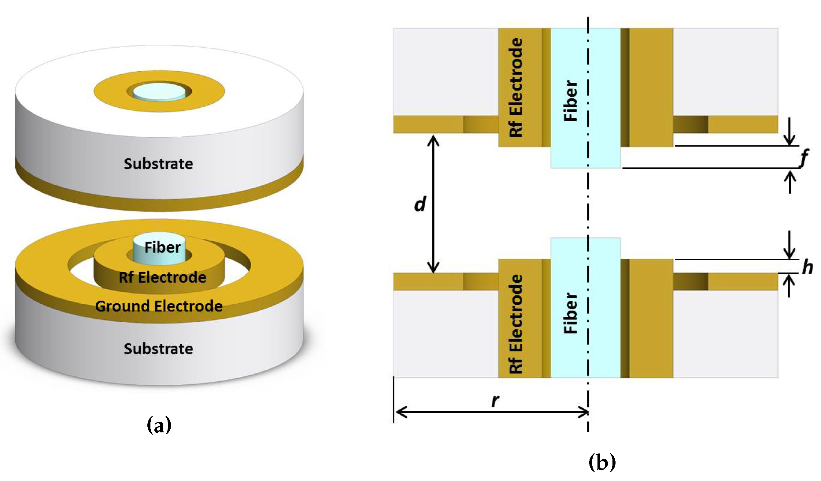
The electrode geometry considered in this article is based on the endcap ion trap described in Takahashi el al. [20]. The entire trap is hosted by two identical disk-shaped quartz substrates facing each other across an open gap (see Figure 1a). Embedded in the substrates, two tubular cylinders along the central axis work as rf electrodes but also provide access for optical fibers. These electrodes are surrounded by concentric ground electrodes plated on the surfaces of the substrates. The two optical fibers inside the rf electrodes are coated with highly reflective coatings on their end facets. These coated end facets serve as mirrors for the Fabry–Perot optical cavity that is formed across the gap. In order to accommodate 200 m diameter optical fibers, the rf electrodes have an inner diameter of 250 m with an outer diameter of 500 m. The 50 m radial gap between the fibers and the inner surfaces of the rf electrodes allows for independent positioning of the fibers inside the rf electrodes in both transverse and axial directions. In this way, the overlap between the ion and the cavity mode can be optimized. Due to the small fiber diameter, the fibers must be mounted close to their end facets for the necessary mechanical stability. From this constraint, we set the thickness of the quartz substrates to 250 m. In this way, the distance between the mount of the fibers and their end facets can be less than 1 mm. The inner radius of the ground electrodes is fixed to 350 m. This leaves a 100 m gap between the rf and the ground electrodes. On the other hand, the outer radius (r) of the ground electrodes is varied to optimize the trap geometry. In contrast with the rf electrodes, the ground electrodes are thin layers on the substrates with thickness of 50 m. The effect of the optical fibers are included in the simulations as two glass cylinders of radius 100 m with relative permittivity = 2.09. Similarly, the quartz substrates are modeled with a relative permittivity of 4.5. The vertical dimensions, i.e., the distance between the two ground electrodes (d), the protrusion of the rf electrodes with respect to the ground electrodes (h) and the recession/protrusion of the fibers with respect to the rf electrodes (f) are all treated as optimizing parameters in the subsequent sections (see Figure 1b).
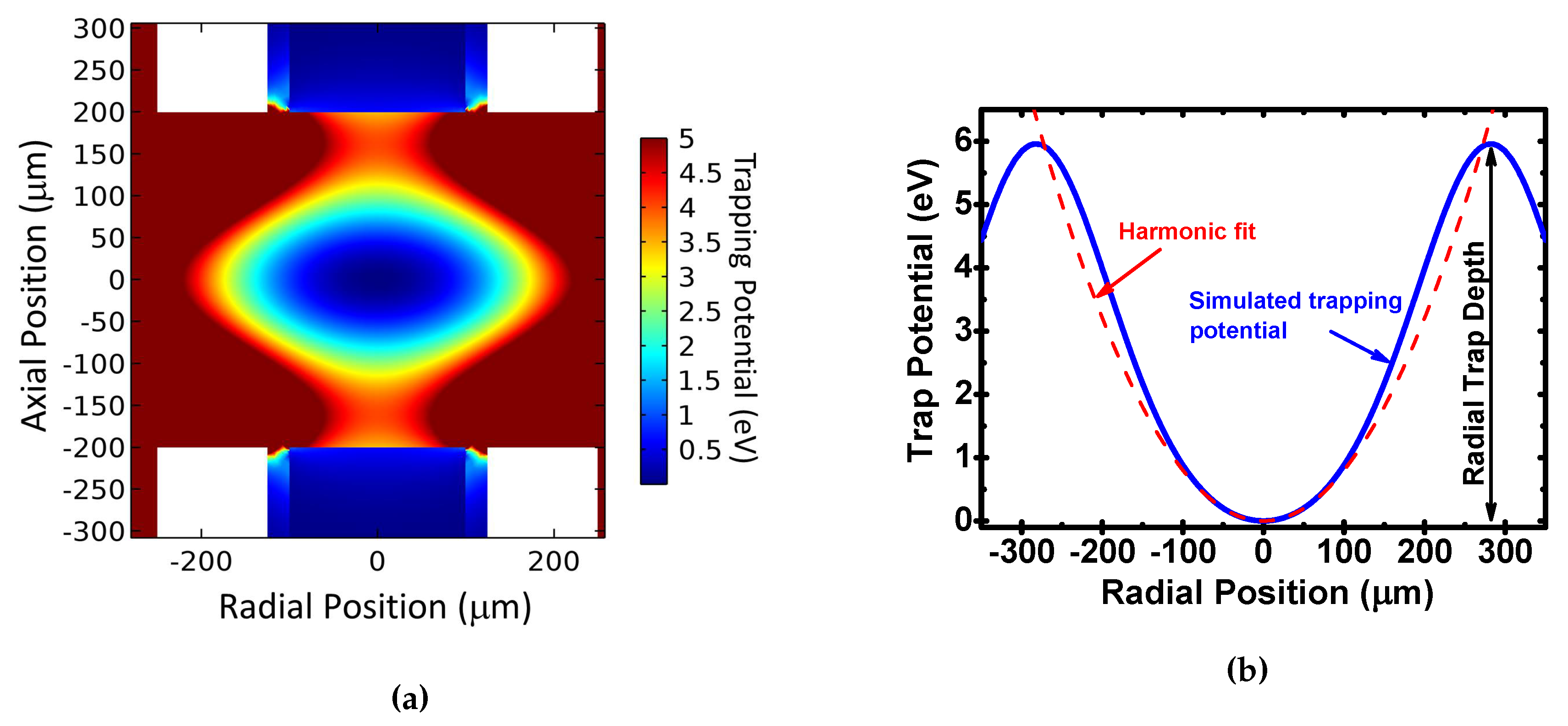
By applying an rf voltage in phase to the rf electrodes, a ponderomotive potential is created with a local minimum in the middle of the gap (see Figure 2). We numerically simulate the electrostatic field of the electrode configuration with the finite element simulation software Comsol Multiphysics and calculate the trapping pseudopotential through
with the ion charge q, its mass m and the angular frequency of the rf voltage Ω. Throughout this article, we use a voltage on the rf electrodes of 200 V at a frequency of 20 MHz and calcium ions with and where and e are the atomic mass unit and the elementary charge, respectively. The voltage and rf frequency are typical values for ion traps of similar size and the specific values are chosen for convenience.
We characterize the trap in terms of the trap depth and the secular frequency of the trapped calcium ions. The trap depth is extracted as the minimal potential barrier height in the radial and axial directions (see Figure 2). To determine the secular frequency, the ponderomotive potential given by Equation (1) is fitted by a second order polynomial and the secular frequency ω is then determined through
with the quadratic fitting coefficient . To ensure that the fitting is not distorted by the anharmonicity of the potential at larger distances from the trap center, we limit the fitting range to less than m around the trap center.
2.1. Radius of the Ground Electrodes
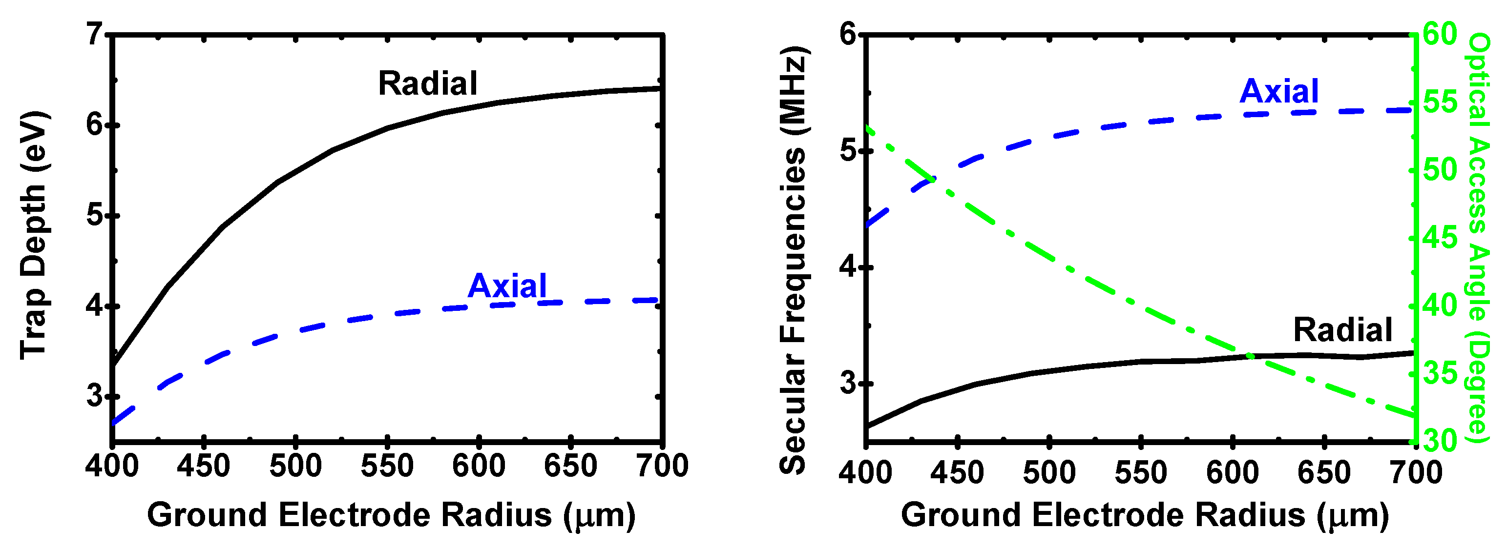
The outer radius of the ground electrodes is one of the dimensions which determines the optical access to the trapped ions. Several laser beams are required to cool the ions. At least one of these laser beams must have a non-vanishing wave vector projection on the vertical trap axis to provide axial cooling. The minimal accessible angle of this laser beam with respect to the trap axis is principally determined by the distance d between the two ground electrodes and their outer radius r. Firstly, we investigate the effect of the radius on the characteristics of the trapping potential. For this, we set the protrusion of the rf electrodes to zero (h = 0) so that they are level with the ground electrodes. Additionally, the fibers are made flush with the edges of the rf electrodes (f = 0) and the electrodes are separated by d = 400 m. In this way, all parameters are set to be constant except for the outer radius of the ground electrodes, which has been changed from r = 400 m to r = 700 m.
Figure 3 shows the potential depths and secular frequencies along the radial and axial directions as a function of the ground electrode radius. For radii below 550 m, the trap depths increase rapidly with increasing radius. However, above 550 m, the trap depths and secular frequencies settle to within 5% of their values for very large radii. Thus, even though larger ground electrodes improve the trap depths and the secular frequencies, the gains are small for radii above 550 m, while the optical access angle decreases steadily.
2.2. Ground Electrode Separation
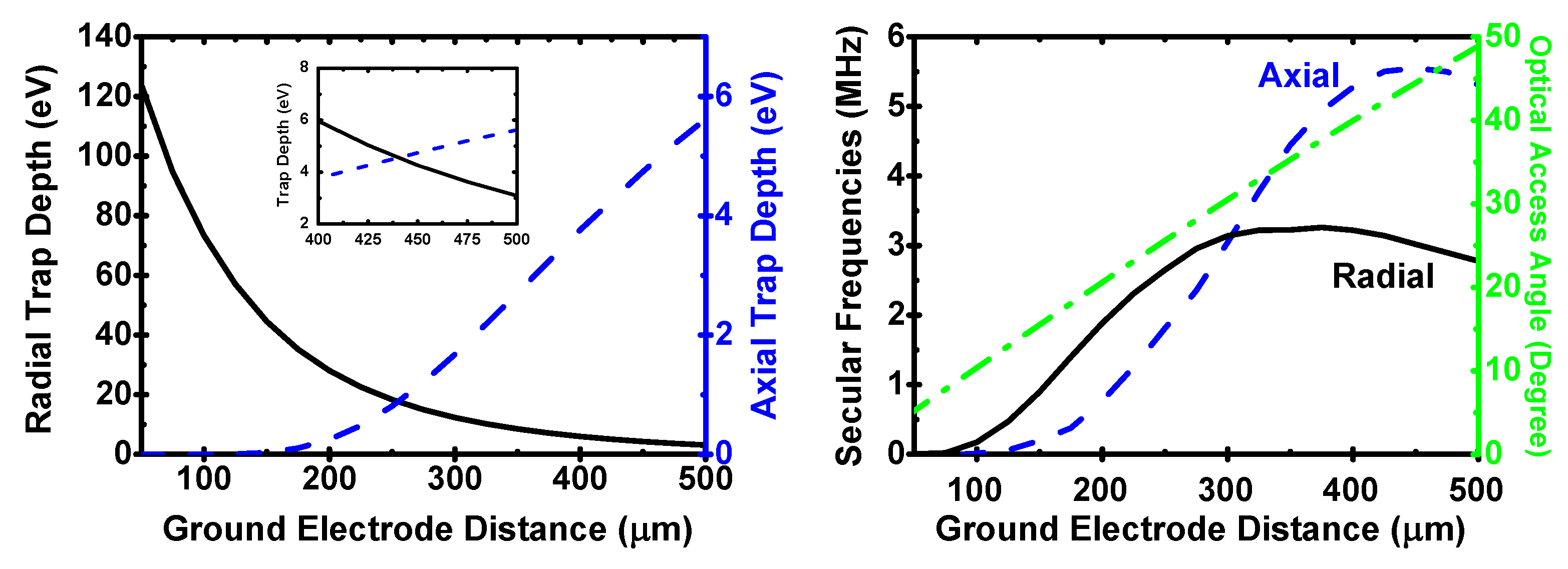
Besides the radius of the ground electrodes, another constraint on the optical access is the separation distance between the two ground electrodes. We have simulated the pseudopotential for varying distance between the opposed electrodes from d = 50 m to d = 500 m. The outer radius of the ground plates is fixed at r = 550 m. The relative height of the rf electrode h and the fiber recess f are both set to 0 m. The axial and radial depths, secular frequencies and optical access angle are shown in Figure 4.
Along the radial direction, the trap depth increases with decreasing electrode separation and very large depths (>100 eV) can be achieved for small separations. However, the axial depth rapidly decreases for small electrode separations and drops below 1 eV for electrode separations below 270 m. The trap depths in both directions become equal at a ground electrode separation of 430 m. While there is a significant difference in the trap depths between the axial and radial directions, the secular frequencies are comparably similar for separations above 200 m. The secular frequencies increase with increasing electrode separation until they reach a maximum at 300 m in the radial and at 350 m in the axial direction, respectively. Here, we choose d = 400 m as a good compromise to achieve large enough trap depths (>4 eV) and high secular frequencies (>2 MHz) in both radial and axial directions.
2.3. Protrusion of the rf Electrodes
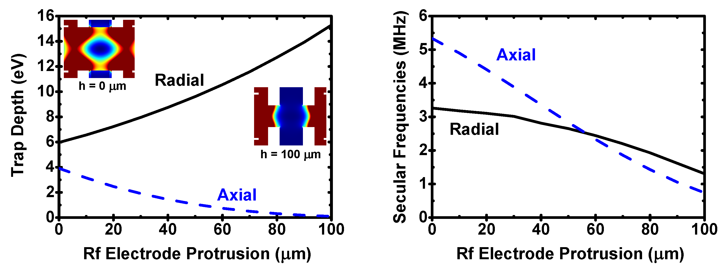
In addition to the planar trap geometry, we have also investigated how the trapping characteristics vary when changing the relative protrusion (h) of the rf electrodes with respect to the ground electrodes. In this simulation, the recess of the fiber faces is zero (f = 0 m), the separation distance between ground plates is d = 400 m and the external radius of the ground electrodes is r = 550 m. The relative height of the rf electrodes has been changed from h = 0 m to h = 100 m, thus the distance between the rf electrodes changes accordingly from 400 m to 200 m. The rf electrode height of h = 0 m corresponds to a surface electrode structure, which is well suited for micro-fabrication, whereas h > 0 m corresponds to an endcap style trap. Even though retracted rf electrodes (h < 0 m) may be advantageous, the precise fabrication of such a structure is difficult. Therefore, here, we only consider h > 0 m.
Figure 5 shows the potential depths and the secular frequencies along the radial and axial directions. While the radial depth steadily increases for larger values of h, the axial depth decreases at the same time. For small electrode separations, the trap center is essentially shielded by the rf electrodes, leading to a reduced confinement along the trap axis (see the insets in Figure 5). On the other hand, the secular frequencies in both directions decrease monotonically with increasing h. Therefore, the largest overall trap depth and highest secular frequencies are obtained for the planar trap geometry (h = 0 m) for this electrode configuration.
2.4. Fiber Recession and Protrusion
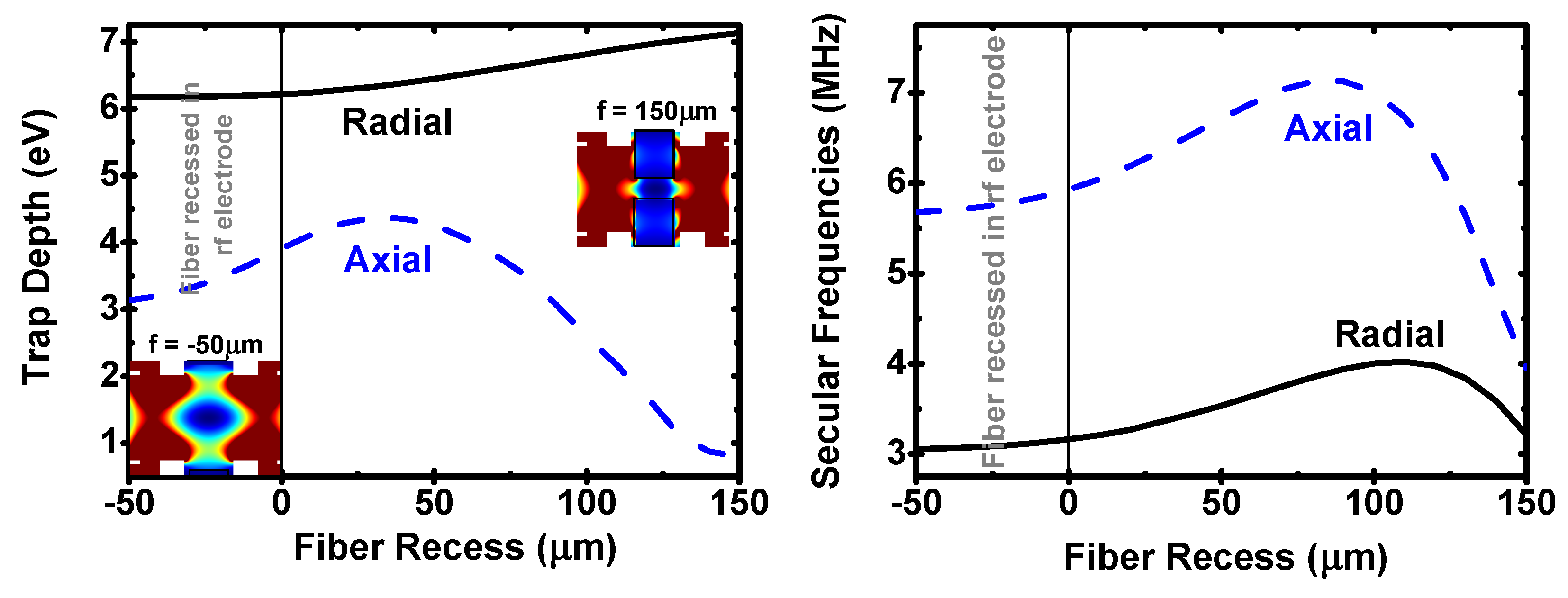
The length of the fiber cavity is a crucial parameter for the ion-cavity coupling. Therefore, it is important to understand how the fibers’ axial positions influence the ponderomotive potential for a given electrode geometry. For recessed fibers in the rf electrodes, the dielectric material is well shielded from the trapping field. This, however, increases the minimal achievable cavity length and thus decreases the ion-cavity coupling. Smaller cavity lengths can be achieved by protruding the fibers from the rf electrodes, which, in turn, exposes the dielectric fiber material to the trapping field. To investigate this, we have studied the dependence of the potential depths and secular frequencies on the fiber recession/protrusion. The positions of the fibers are symmetrically varied with respect to the edges of the rf electrodes, from recession (f = −50 m) to protrusions of up to f = 150 m. The trap geometry is that of the planar electrodes (h = 0 m) with d = 400 m and r = 550 m.
The simulated trap depths and secular frequencies are shown in Figure 6. When the fibers are shielded by the rf electrodes (f < 0), their effects on the trapping field is small. Only the axial trap depth increases steadily until it reaches a maximum of 4.5 eV at a fiber protrusion of 30 m; from there, it declines to below 1 eV at a protrusion of 150 m. Furthermore, the axial secular frequency increases steadily from f = −50 m until it reaches a maximum of ∼7.5 MHz at around f = 90 m from where it rapidly decreases. The radial frequency follows a similar trend but reaches its maximum at slightly larger protrusions (110 m). The change of the radial trap depth, however, remains within 15% of its fully recessed value. The dielectric material of the fibers initially deforms the trapping electric field such that it strengthens the trap confinement. However, the same deformation eventually results in an effective shielding of the trap center from the fields created by the rf electrodes for large fiber protrusions (see the insets in Figure 6).
From the above results, a protrusion of 30–50 m appears to be promising in terms of the trapping stability. It also enhances the ion-cavity coupling compared to the recessed cases. On the other hand, protruded unshielded fibers could accumulate stray charges on their surfaces and could cause instability, which is not included in the above simulations. These cases should be investigated carefully in the actual experimental setup to obtain the best balance between the trapping stability and ion-cavity coupling. Our trap design allows in situ alignment of the fiber recession/protrusion depending on those experimental needs.
2.5. Fiber Cavity Displacement
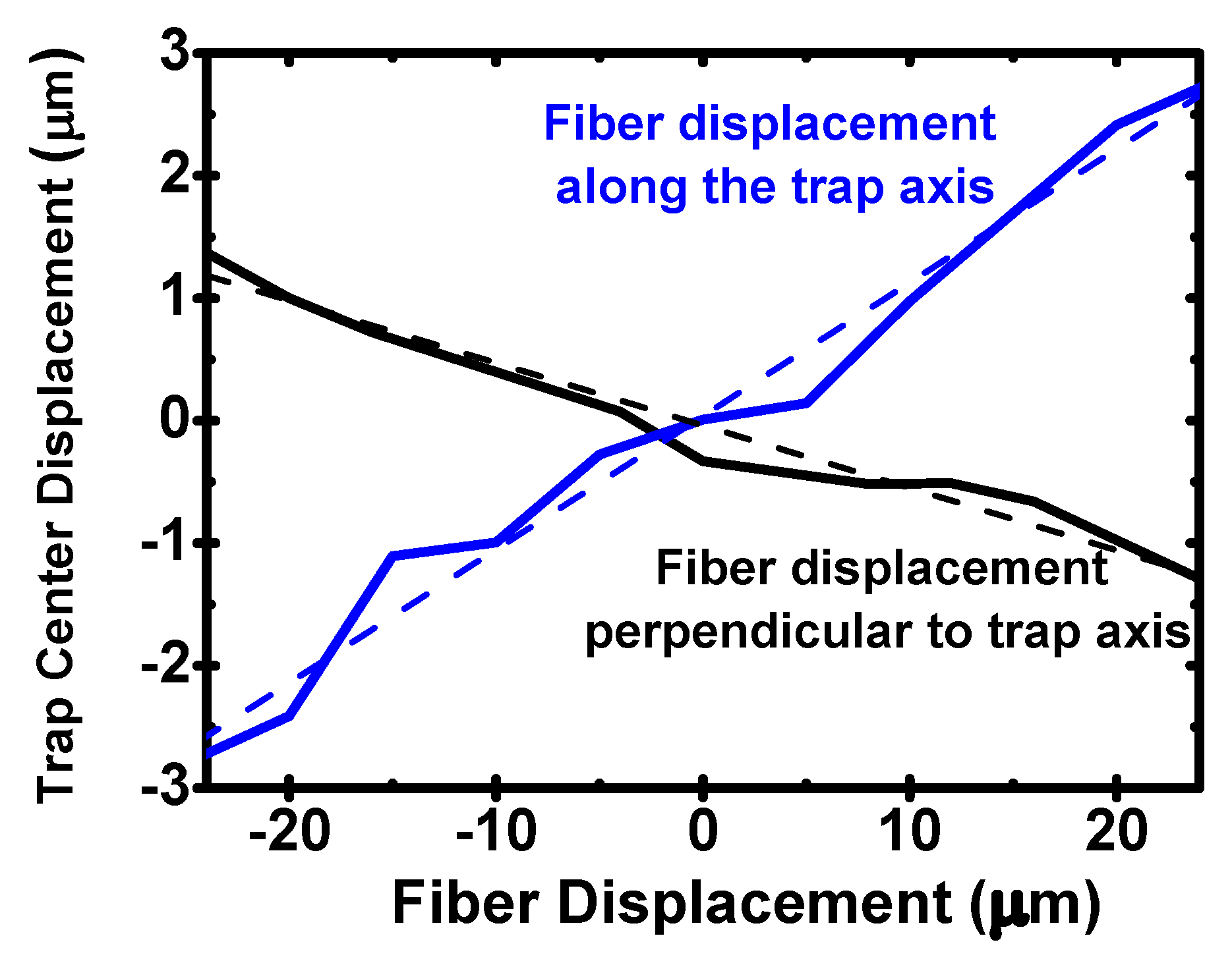
The surfaces of the fiber end facets for a high finesse fiber cavity are normally machined with a CO laser [21,22]. Due to the imperfection in this machining process, the axis of the fiber cavity does not always coincide with the axis defined by the geometric centers of the fibers. In that case, the fibers inside the rf electrodes need to be displaced in order to optimize the overlap between the trapped ion and the cavity mode. Then, there is a possibility that this displacement of the fiber cavity itself modifies the trapping potential. We have investigated this possibility by looking at the shift of the trap center associated with the displacement of the fiber cavity. The investigated trap geometry is planar (h = 0 m) with the distance between the opposed electrodes d = 400 m and the outer radius of the ground electrodes r = 550 m. The position of the fiber cavity is displaced perpendicularly to the central axis of the rf electrodes by ±24 m. In addition, we have conducted simulations of axial fiber cavity displacements by m from the symmetric configurations. The results of both simulations are shown in Figure 7. Due to the relatively small effects, the results contain significant numerical noise.
For the displacement perpendicular to the trap axis, the trap center is shifted also perpendicular to the trap axis. In the case of axial cavity displacement, the trap center is also displaced only axially. The effects of the cavity displacements on the trap center position is small in both cases. For the investigated displacement range, the trap center shifts approximately linearly with the cavity displacement. However, the effect is larger for the axial cavity displacements (slope of 10%) compared to a slope of 5% for the perpendicular displacements. We have also investigated the displacement of the trap center due to a lateral antisymmetric shift of the fibers within the rf electrodes. However, the results show no noticeable shift of the trap center.
3. Practical Trap Design
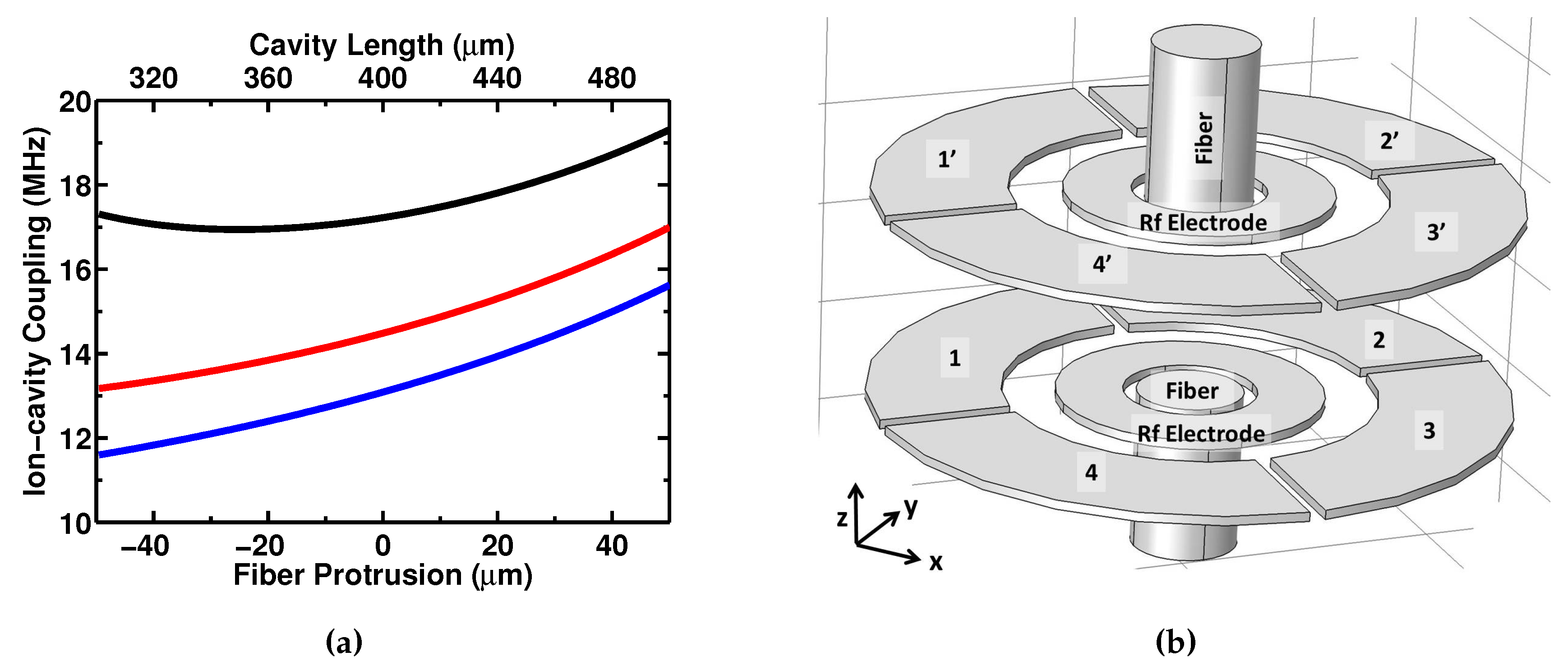
Based on our numerical studies of the trap geometry in terms of its effects on the trapping potential, in this section, we devise a practical trap design which also takes technical considerations into account. We employ the , = 1/2 −, = 3/2 transition of Ca-ion as a resonant transition with the optical cavity. Other ion species and atomic transitions will potentially result in a different trap geometry. The crucial parameters to consider are the coherent coupling strength between the ion and cavity, and the localization of the ion within the cavity. On the other hand, practical considerations such as the ease of trap fabrication, the frequency and amplitude of the applied rf voltages, and possibility to efficiently cool and state-prepare the trapped ion must also be taken into account. Weighing the importance of these considerations against each other is a complicated process. Here, we mainly limit the optimization to simultaneously maximizing the axial secular frequency and the coherent coupling strength. In addition, we keep the ion’s axial temperature between 3–4 times the Doppler cooling limit, requiring an optical access angle of 30–40. This ensures that the amplitude of the ion’s thermal motion is less than 5% of the transition wavelength at the highest stable axial secular frequency with a 20 MHz trap drive frequency. With the cavity axis aligned to coincide with the trap axis, the localization of the ion along the cavity axis at a constant temperature can be optimized by increasing the axial secular frequency. Considering the ground electrode radius, we have chosen 550 m. Below this radius, the secular frequencies decrease rapidly, whereas there is no significant increase above this value. However, slight modifications of this value do not have a significant effect, and we have chosen this value as it simplifies the segmentation of the ground electrode for micromotion compensation. Varying the ground electrode separation results in a maximal axial secular frequency at a separation of 430 m. Between 400 and 500 m, the axial secular frequency is nearly constant and we have chosen a distance of 400 m, which allows a slightly shorter cavity length with the required optical access angle. Similarly, the axial secular frequency is maximal for an rf electrode protrusion of h = 0 m. Figure 8a shows calculated coherent ion-cavity coupling strength as a function of the fiber protrusion for spherical mirrors. The range of protrusion corresponds to the cavity length between 300 m and 500 m. For all the radii of curvature presented in the figure, the coupling strength exceeds the atomic polarization decay rate of the ion (= 11.2 MHz) at any point in the figure. If the cavity has a reasonably high finesse of more than 20,000, these coupling strengths satisfy the strong coupling condition. Therefore, with our trap design, strong coupling of a single ion can be achieved.
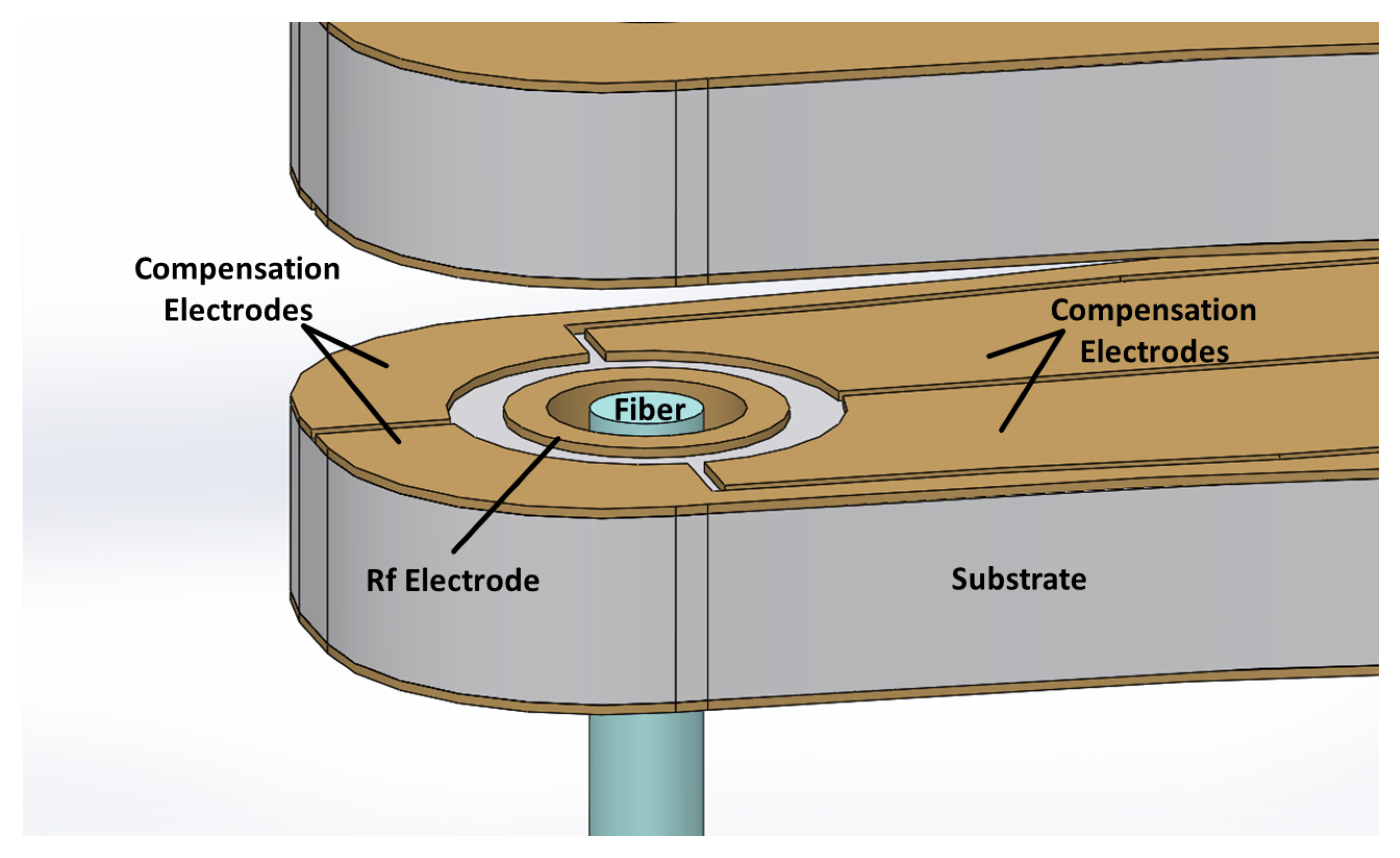
In addition to the design of the rf trapping electrodes, the compensation of dc stray fields must be also accommodated for. These stray fields may originate from patch potentials on the electrodes or charges on the dielectric surfaces and may cause micromotion of the trapped ions. To be able to create static compensation fields in an arbitrary direction, the ground electrodes are segmented as shown in Figure 8b and now applied with dc voltages. By ac coupling these electrodes and ensuring that the gap size between the segments are much smaller than the ion-electrode distance, the effect on the rf trapping potential is negligible.
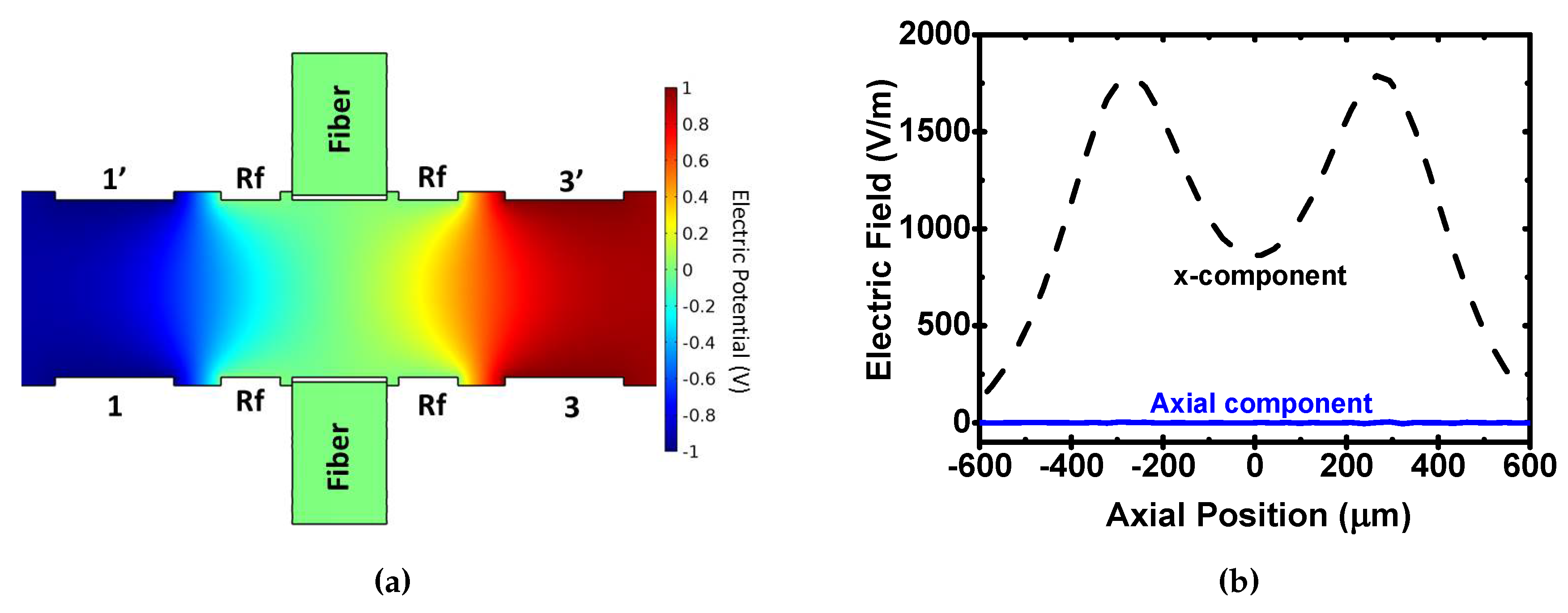
By applying voltages to a combination of pairs of these segmented electrodes, any static field can be generated at the trap center. A simulation of the fields from different combinations of electrodes are shown in Figure 9 and Figure 10. To compensate a field perpendicular to the trap axis along the x-direction (see Figure 8b for the coordinate system), the segments 2, 2, 4 and 4 are grounded whereas a voltage is applied on the 1 and 1 electrodes and a voltage with the same amplitude, but an opposite sign is applied to electrodes 3 and 3. In a similar way, fields along the y-direction can be produced. Linear combinations of these enables a compensation for any static field in the plane perpendicular to the trap axis.
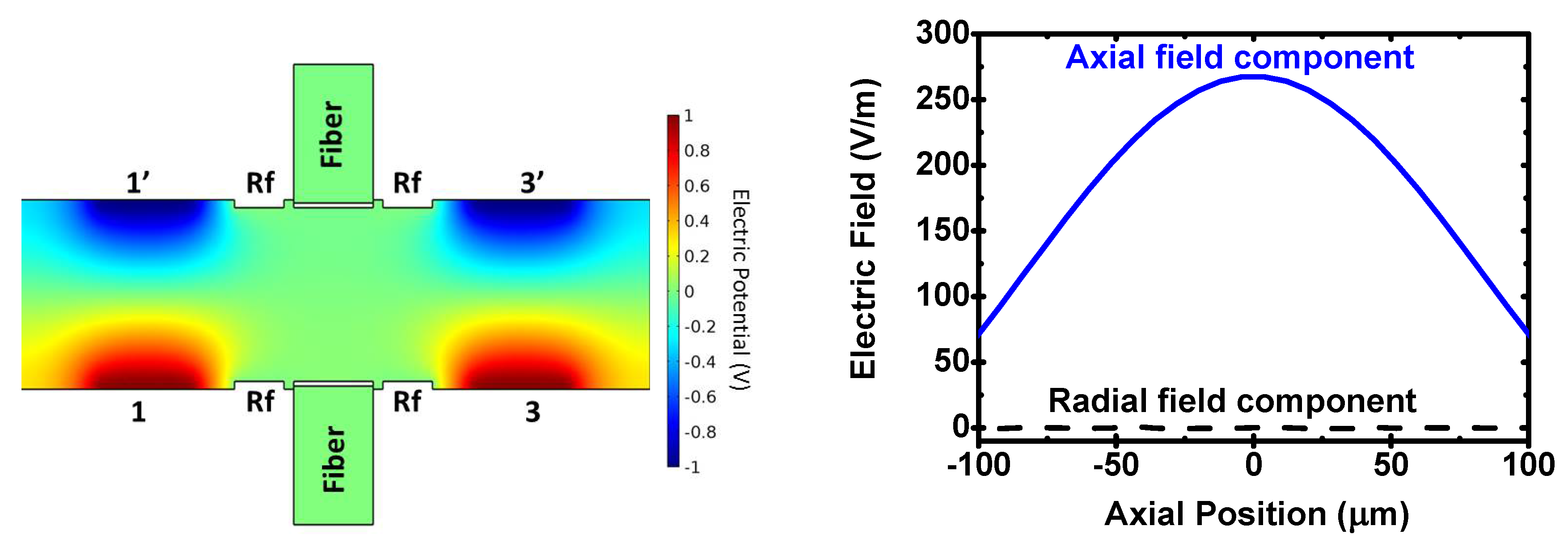
Similarly, to compensate electric fields along the trap axis, a voltage can be applied to all compensation electrodes in one half of the trap (1, 2, 3 and 4), whereas the opposite voltage is applied to the electrodes 1, 2, 3’ and 4 on the other half. Combining this voltage configuration with the abovementioned transverse compensation can complete a full cancellation of an arbitrary stray field at the trap center.
In order to mount the electrode structure, the electrodes are machined on a lever structure as shown in Figure 11, which can be easily mounted at a significant distance from the trap center to avoid any deterioration of the optical access due to the mounting structure and electric connections. The compensation electrodes are patterned on the inner face of the lever structure as shown in Figure 11. The rf electrode runs through the hole to the other face of the structure on which an electrical path for an rf supply can be made.
4. Conclusions
In conclusion, we have proposed a novel ion trap design to achieve strong ion-cavity coupling. We have systematically studied the effects of the electrode geometries as well as the cavity mirrors on the trapping potential depths and secular frequencies. Based on these systematic analysis, we have created an optimized design by taking technical requirements such as stray field compensation into account. As a result, we have devised a design which should be capable of stable trapping of ions in a fiber cavity with a length of 500 m.
Acknowledgments
We gratefully acknowledge support from the Engineering and Physical Sciences Research Council through the UK Quantum Technology Hub: NQIT—Networked Quantum Information Technologies (EP/M013243/1) and EP/J003670/1.
Author Contributions
Alejandro Márquez Seco, Hiroki Takahashi and Matthias Keller all contributed to the simulations, their analysis and the writing of this article.
Conflicts of Interest
The authors declare no conflict of interest.
References
- Kuhn, A.; Hennrich, M.; Bondo, T.; Rempe, G. Controlled Generation of Single Photons from a Strongly Coupled Atom-Cavity System. Appl. Phys. B 1999, 69, 373–377. [Google Scholar] [CrossRef]
- Wilk, T.; Webster, S.; Kuhn, A.; Rempe, G. Single-Atom Single-Photon Quantum Interface. Science 2007, 317, 488–490. [Google Scholar] [CrossRef] [PubMed]
- Ritter, S.; Nölleke, C.; Hahn, C.; Reiserer, A.; Neuzner, A.; Uphoff, M.; Mücke, M.; Figueroa, E.; Bochmann, J.; Rempe, G. An elementary quantum network of single atoms in optical cavities. Nature 2012, 484, 195–200. [Google Scholar] [CrossRef] [PubMed]
- Leibfried, Y.; Blatt, R.; Monroe, C.; Wineland, D. Quantum dynamics of single trapped ions. Rev. Mod. Phys. 2003, 75, 281–324. [Google Scholar] [CrossRef]
- Guthöhrlein, G.R.; Keller, M.; Hayasaka, K.; Lange, W.; Walther, H. A single ion as a nanoscopic probe of an optical field. Nature 2001, 414, 49–51. [Google Scholar] [CrossRef] [PubMed]
- Mundt, A.B.; Kreuter, A.; Becher, C.; Leibfried, D.; Eschner, J.; Schmidt-Kaler, F.; Blatt, R. Coupling a Single Atomic Quantum Bit to a High Finesse Optical Cavity. Phys. Rev. Lett. 2002, 89, 103001. [Google Scholar] [CrossRef] [PubMed]
- Keller, M.; Lange, B.; Hayasaka, K.; Lange, W.; Walther, H. Continuous generation of single photons with controlled waveform in an ion-trap cavity system. Nature 2004, 431, 1075–1078. [Google Scholar] [CrossRef] [PubMed]
- Barros, H.G.; Stute, A.; Northup, T.E.; Russo, C.; Schmidt, P.O.; Blatt, R. Deterministic single-photon source from a single ion. New J. Phys. 2009, 11, 103004. [Google Scholar] [CrossRef]
- Stute, A.; Casabone, B.; Schindler, P.; Monz, T.; Schmidt, P.O.; Brandstätter, B.; Northup, T.E.; Blatt, R. Tunable ion-photon entanglement in an optical cavity. Nature 2012, 485, 482–485. [Google Scholar] [CrossRef] [PubMed]
- Casabone, B.; Stute, A.; Friebe, K.; Brandstätter, B.; Schüppert, K.; Blatt, R.; Northup, T.E. Heralded Entanglement of Two Ions in an Optical Cavity. Phys. Rev. Lett. 2013, 111, 100505. [Google Scholar] [CrossRef] [PubMed]
- Law, C.K.; Kimble, H.J. Deterministic generation of a bit-stream of single-photon pulses. J. Mod. Opt. 1997, 44, 2067–2074. [Google Scholar] [CrossRef]
- Kimble, H.J. Strong interactions of single atoms and photons in cavity QED. Phys. Scr. 1998, 1998, 127. [Google Scholar] [CrossRef]
- Harlander, M.; Brownnutt, M.; Hänsel, W.; Blatt, R. Trapped-ion probing of light-induced charging effects on dielectrics. New J. Phys. 2010, 12, 093035. [Google Scholar] [CrossRef]
- Brandstätter, B.; McClung, A.; Schüppert, K.; Casabone, B.; Friebe, K.; Stute, A.; Schmidt, P.O.; Deutsch, C.; Reichel, J.; Blatt, R.; et al. Integrated fiber-mirror ion trap for strong ion-cavity coupling. Rev. Sci. Instrum. 2013, 84, 123104. [Google Scholar] [CrossRef] [PubMed]
- Cetina, M.; Bylinskii, A.; Karpa, L.; Gangloff, D.; Beck, K.M.; Ge, Y.; Scholz, M.; Grier, A.T.; Chuang, I.; Vuletić, V. One-dimensional array of ion chains coupled to an optical cavity. New J. Phys. 2013, 15, 053001. [Google Scholar] [CrossRef]
- Leibrandt, D.D.; Labaziewicz, J.; Vuletić, V.; Chuang, I.I. Cavity Sideband Cooling of a Single Trapped Ion. Phys. Rev. Lett. 2009, 103, 103001. [Google Scholar] [CrossRef] [PubMed]
- Sterk, J.D.; Luo, L.; Manning, T.A.; Maunz, P.; Monroe, C. Photon collection from a trapped ion-cavity system. Phys. Rev. A 2012, 85, 062308. [Google Scholar] [CrossRef]
- Hunger, D.; Steinmetz, T.; Colombe, Y.; Deutsch, C.; Hänsch, T.W.; Reichel, J. A fiber Fabry–Perot cavity with high finesse. New J. Phys. 2010, 12, 065038. [Google Scholar] [CrossRef]
- Steiner, M.; Meyer, H.M.; Deutsch, C.; Reichel, J.; Köhl, M. Single Ion Coupled to an Optical Fiber Cavity. Phys. Rev. Lett. 2013, 110, 043003. [Google Scholar] [CrossRef] [PubMed]
- Takahashi, H.; Wilson, A.; Riley-watson, A.; Oručević, F.; Seymour-Smith, N.; Keller, M.; Lange, W. An integrated fiber trap for single-ion photonics. New J. Phys. 2013, 15, 053011. [Google Scholar] [CrossRef]
- Hunger, D.; Deutsch, C.; Barbour, R.J.; Warburton, R.J.; Reichel, J. Laser micro-fabrication of concave, low-roughness features in silica. AIP Adv. 2012, 2, 012119. [Google Scholar] [CrossRef]
- Takahashi, H.; Morphew, J.; Oručević, F.; Noguchi, A.; Kassa, E.; Keller, M. Novel laser machining of optical fibers for long cavities with low birefringence. Opt. Express 2014, 22, 31317–31328. [Google Scholar] [CrossRef] [PubMed]
Figure 1.
(a) Three-dimensional mode of the ion trap assembly: Two optical fibers are surrounded by concentric rf electrodes and two rings that act as ground electrodes. (b) Vertical cross section of the trap. The parameters presented in this figure are the external radius of the ground electrodes (r), the separation distance between the ground electrodes (d), the relative height of the rf electrodes with respect to the ground electrodes (h) and the fiber protrusion/recession with respect to the the rf electrodes (f).

Figure 2.
(a) Cross section of the pseudopotential with an outer radius of the ground electrodes r = 400 μm, ground electrode separation distance d = 550 μm, rf electrode height of h = 0 μm and a fiber recess of f = 0 μm. The applied rf voltage is 200V at a frequency of 20 MHz. (b) Radial trapping potential (blue line). The trap depth is measured as the height of the trapping potential and the secular frequency is determined by fitting a quadratic function around the trap center (red line).

Figure 3.
Trap depth, secular frequencies, and optical access angles as a function of the outer radius of the ground electrodes.
Figure 3.
Trap depth, secular frequencies, and optical access angles as a function of the outer radius of the ground electrodes.

Figure 4.
Trap depth and secular frequencies along the radial and axial directions when changing the separation distance between the planar ground electrodes. The inset shows a close-up of the radial and axial trap depths for separations between 400–500 m.
Figure 4.
Trap depth and secular frequencies along the radial and axial directions when changing the separation distance between the planar ground electrodes. The inset shows a close-up of the radial and axial trap depths for separations between 400–500 m.

Figure 5.
Radial and axial trap depths and secular frequencies as a function of the protrusion of the rf electrodes with respect to the ground electrodes. The insets show the shapes of the trapping potentials at h = 0 m and at h = 100 m.
Figure 5.
Radial and axial trap depths and secular frequencies as a function of the protrusion of the rf electrodes with respect to the ground electrodes. The insets show the shapes of the trapping potentials at h = 0 m and at h = 100 m.

Figure 6.
Radial and axial trap depth and secular frequency when changing the position of the optic fibers with respect to the rf electrodes.
Figure 6.
Radial and axial trap depth and secular frequency when changing the position of the optic fibers with respect to the rf electrodes.

Figure 7.
The shifts of the trap center as a function of the cavity displacement in the axial and perpendicular directions. The dotted lines are linear fits to the data.
Figure 7.
The shifts of the trap center as a function of the cavity displacement in the axial and perpendicular directions. The dotted lines are linear fits to the data.

Figure 8.
(a) Coherent ion-cavity coupling strength as a function of the fiber protrusion for different radii of curvature Rc of the fiber mirrors. The cavity is assumed to have identical mirrors on both sides. Rc = 300 μm (black), 400 μm (red) and 500 μm (blue). The calculations are based on the Equation (2) in the reference [12]. (b) Segmented rf-ground electrodes for compensation of stray electric fields.

Figure 9.
(a) Cross-section of the ion trap along the yz-plane with the electric potential. (b) The electric field generated with a voltage of +1 V to the 1 and 1’ electrodes and −1 V to electrodes 3 and 3’. All other electrodes are at ground potential.
Figure 9.
(a) Cross-section of the ion trap along the yz-plane with the electric potential. (b) The electric field generated with a voltage of +1 V to the 1 and 1’ electrodes and −1 V to electrodes 3 and 3’. All other electrodes are at ground potential.

Figure 10.
(a) Cross-section of the ion trap along the yz-plane with the electric potential. (b) The generated electric field generated by applying a voltage of +1 V to electrodes 1,2,3 and 4 and −1 V to electrodes 1, 2, 3’, and 4.
Figure 10.
(a) Cross-section of the ion trap along the yz-plane with the electric potential. (b) The generated electric field generated by applying a voltage of +1 V to electrodes 1,2,3 and 4 and −1 V to electrodes 1, 2, 3’, and 4.

Figure 11.
Trap assembly on a lever structure.

© 2016 by the authors; licensee MDPI, Basel, Switzerland. This article is an open access article distributed under the terms and conditions of the Creative Commons Attribution (CC-BY) license (http://creativecommons.org/licenses/by/4.0/).
Share and Cite
MDPI and ACS Style
Márquez Seco, A.; Takahashi, H.; Keller, M. Novel Ion Trap Design for Strong Ion-Cavity Coupling. Atoms 2016, 4, 15. https://doi.org/10.3390/atoms4020015
AMA Style
Márquez Seco A, Takahashi H, Keller M. Novel Ion Trap Design for Strong Ion-Cavity Coupling. Atoms. 2016; 4(2):15. https://doi.org/10.3390/atoms4020015
Chicago/Turabian StyleMárquez Seco, Alejandro, Hiroki Takahashi, and Matthias Keller. 2016. "Novel Ion Trap Design for Strong Ion-Cavity Coupling" Atoms 4, no. 2: 15. https://doi.org/10.3390/atoms4020015
Note that from the first issue of 2016, this journal uses article numbers instead of page numbers. See further details here.