Dimensional Control of Aircraft Transmission Bodies Using CNC Machines and Neuro-Fuzzy Systems


1
Pratt & Whitney Rzeszów S.A, 35-078 Rzeszów, Poland
2
Department of Applied Mechanics and Robotics, Faculty of Mechanical Engineering and Aeronautics, Rzeszow University of Technology, 35-959 Rzeszów, Poland
*
Author to whom correspondence should be addressed.
Appl. Sci. 2019, 9(19), 4094; https://doi.org/10.3390/app9194094
Submission received: 27 August 2019
/
Revised: 17 September 2019
/
Accepted: 29 September 2019
/
Published: 30 September 2019
(This article belongs to the Section Mechanical Engineering)
Abstract
:Featured Application
The results of the work may find potential application in quality control of parts after machining.
Abstract
The article deals with the selected aspects of quality control of aircraft accessory drive train bodies. The work presents the concept of control of selected dimensional and shape characteristics. The key issue under consideration is the possibility of replacing the coordinate measuring machines (CMM) in selected measuring operations with a computerized numerical control (CNC) machine, which leads to a lower load on the measuring laboratory. In order to determine the relationship between the measurement results on the CMM in an unmounted state and the results of measurements on the CNC machine in the mounted state, a neuro-fuzzy model was used. The problem is presented for a selected component, which is the cover of the transmission body. Detailed analysis, calculations and neuro-fuzzy modelling of the dependencies between the measurement data were carried out for the selected key geometric characteristic, i.e., the bearing seat position deviation. The obtained results are acceptable from the point of view of quality control.
1. Introduction
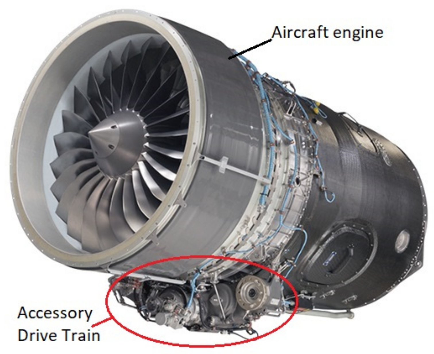
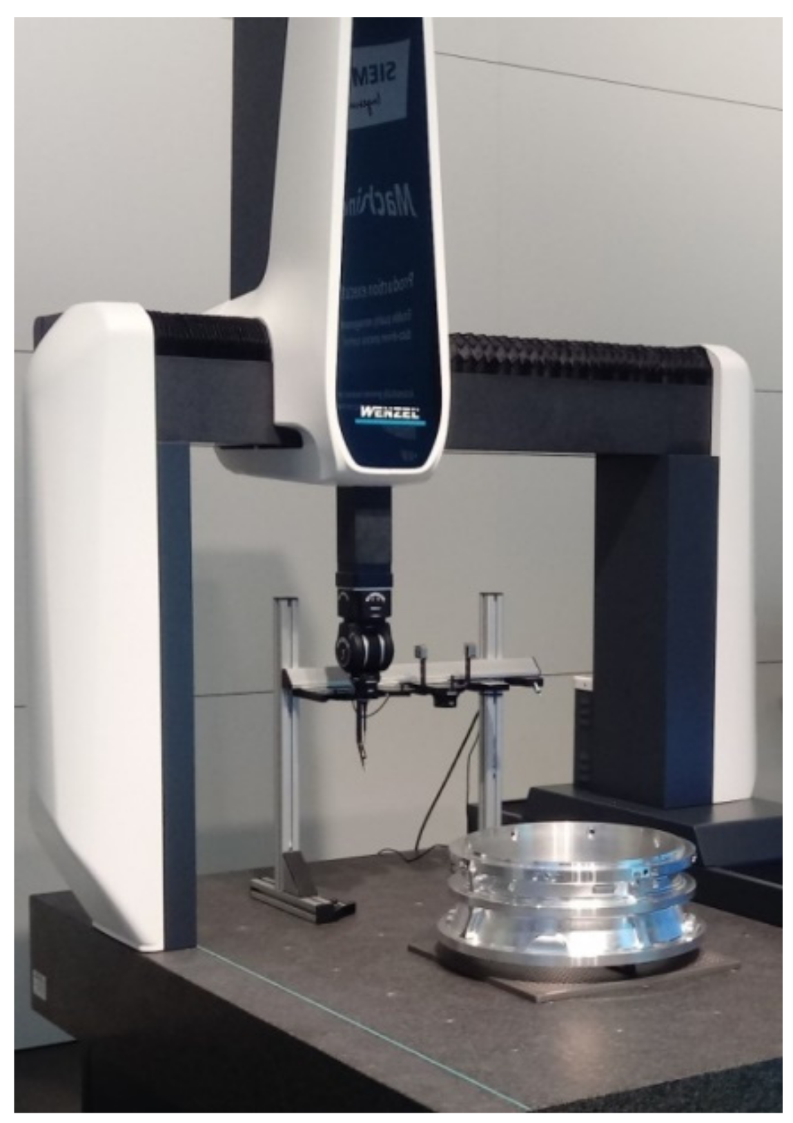
The article deals with the selected aspects of quality control of aircraft accessory drive train (ADT) bodies (Figure 1). In the case of the most responsible elements of aircraft construction, such as engine and transmission components, all manufactured items are checked. Due to the required accuracy of workpieces, dimensional and shape characteristics are obtained using coordinate measuring machines (CMM) (Figure 2). Due to their versatility, they currently constitute standard solutions for determining the dimensional and shape characteristics of aircraft transmissions. The biggest drawback of this type of approach is the high cost of purchasing and maintaining CMMs and long measurement time. Therefore, the measuring laboratory is very often the so-called bottleneck of the production process, because usually one CMM machine is used to serve several lines of machine tools.
It should be noted that not all measurements must be performed with the same high accuracy. An alternative to some measurements made with CMMs are measurements made using CNC machines [1]. A set of measuring probes has been standard equipment for CNC machining centers for several years. Probes have a measuring element, called the stylus, which has a properly configured shape that enables the measurement of selected geometric quantities. In addition, the CNC machine has dedicated software and a receiver cooperating with the probes, enabling it to take relevant measurements and save the results in the form of CNC system variables or measurement reports.
The control of bodies using traditional methods with the use of sensing devices and special gauges is labor-intensive and expensive due to the need to develop and produce the so-called testers, which are specific to a given design. Such equipment is intended for a particular body and can rarely be adapted to check other parts. In addition, this method of measurement is susceptible to the so-called human factor which causes errors. It also does not allow automatic generation of measurement reports.
The paper presents the problem of determining a selected dimensional characteristic in such a way that the participation of CMM in the measurement process is as small as possible [2]. In the case analyzed in the article, it is not possible to completely eliminate measurements on CMM and replace them only with measurements on a CNC machine. Additionally, in the machining center, the shape–dimensional characteristics are determined in the mounted state, while in the measuring laboratory the characteristics are determined in a free state. This introduces a significant difference in the results of measurements resulting not only from differences in CMM and CNC machine accuracy, but also from deformation of the body after unmounting. The measure of these deformations is the curvature of the selected surface of the body. The paper presents a method for determining bearing seat position deviation based on measurement on a CNC machine and measuring the curvature of a surface on a CMM machine, using neuro-fuzzy models describing the relation between dimensions in the mounted state and free state. This approach allows the reduction of the number of characteristics determined on the CMM, and thus a smaller load on the measuring laboratory.
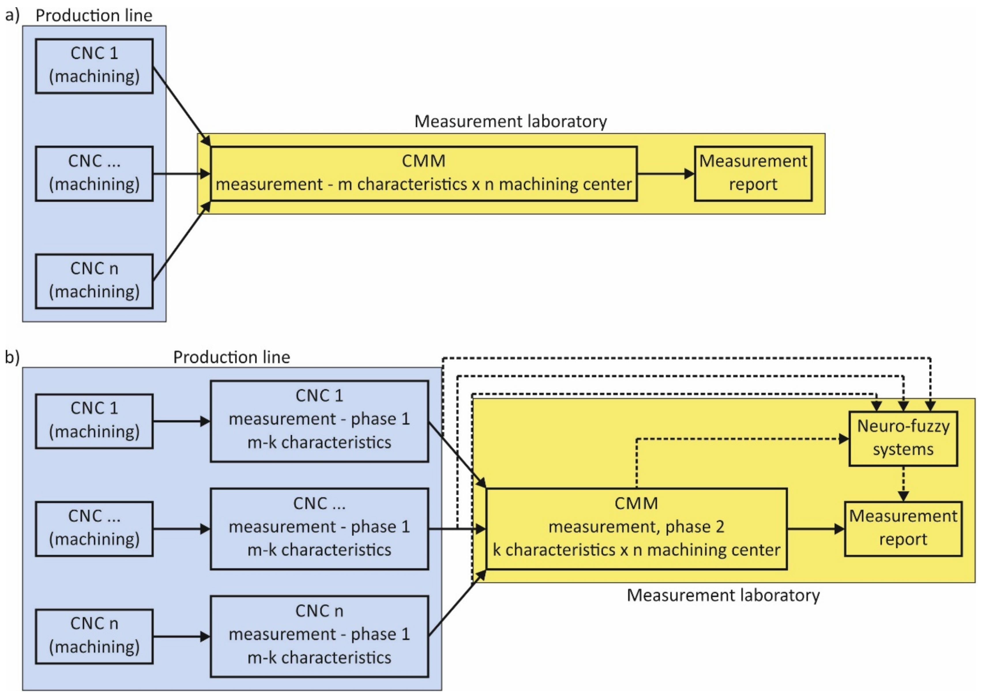
The issue presented in the article has been developed for the needs of Pratt & Whitney Rzeszow. Figure 3a shows the current course of operations in the production of bodies, while Figure 3b shows the course taking into account the new solution developed.
If the number of measurement characteristics k determined on the CMM is much smaller than all the necessary characteristics m, then the solution presented in Figure 3b eliminates the bottlenecking problem and it is economically rational [3]. The necessary condition is the ability to build such computational models that enable the creation of a reliable measurement report.
In the authors’ opinion, the novelty of the proposed solution is the use of neuro-fuzzy systems in the production process, in particular in its metrological part, which streamline the production process. This is due to the distribution of the metrological process into several CNC stations and to relieve the CMM machine. This allows for both time and financial savings, thanks to the relief of more expensive CMM. The whole solution is so-called process innovation, which involves improving the production process to obtain the same product. From the point of view of manufacturing companies, this is an extremely important aspect of building competitive advantage.
Chapter 2 describes aircraft ADT bodies, their specific properties as well as construction and technological features, as well as the reasons for the deformation of the bodies after unmounting from the machining holder. Chapter 3 presents the methodology of experimental tests, the possibility of using neuro-fuzzy systems and considers the selected case of bearing seat position deviation measurement. Chapter 4 analyzes the measurement data and describes the use of neuro-fuzzy models to determine the deviation of the bearing seat position of the ADT body. The quality of results generated by these models is evaluated and a discussion of results is included. The construction of neuro-fuzzy models is not described in detail, because the subjects of their structure, properties and learning are known and widely described in the literature. In this work, neuro-fuzzy systems are treated only as computational tools. Standard learning procedures for these models are available in MATLAB software (Version 9.6.0.1174912 (R2019a) Update 5, The MathWorks, Inc., Natick, MA, USA, 2019). The article is concluded with a summary, which discusses the possibility of applying obtained solutions in the dimensional control of the remaining elements of the analyzed construction.
2. Aircraft Transmission Bodies
2.1. General Characteristics of the Bodies
Aircraft transmission bodies are designed for mounting and mutual arrangement of various elements, assemblies and mechanisms, mainly bearings, shafts and cogwheels. The housings are made as light alloy components, i.e., aluminum or magnesium alloys. They are characterized by a large variety of shapes, dimensions and semi-products used to make them. Due to the required reliability and flight safety, ADT are characterized by specific technological and constructional requirements. They are connected, among others, with the need to minimize the mass of the airframe propulsion unit, high dimensional and shape accuracy and limited space for the housings of the power unit.
The shape complexity of the transmission results from the limited space for its housing. It is also a consequence of the fact that the external shapes of the bodies are not much different from the outlines of the elements inside. In addition, the wall thicknesses of the bodies are small in relation to the dimensions of the transmissions, which results from the weight reduction requirement. Therefore, ADT bodies are classified as so-called thin-walled components. The methods of manufacturing, processing and measuring thin-walled aircraft components are one of the most difficult issues in aircraft production and require the use of special, individualized approaches [4,5,6,7,8].
The aircraft transmission bodies are made as castings with technological allowances. During the machining process carried out in order to give the workpiece the required dimensional and shape features, changes occur in the stressed state resulting from:
For this reason, after removing from the holder, the transmission bodies are subject to geometric deformations.
2.2. Construction and Technological Characteristics
A common feature of various aircraft bodies is the presence of accurately machined flat surfaces (the so-called dividing surface), accurate holes to fix bearings, shafts and other components and a significant number of auxiliary holes—for connecting, mounting, lubricating, etc.
Machined bodies must meet the following requirements:
- Misalignment of important holes up to 0.01 mm and other holes up to 0.05 mm;
- Distance tolerance inter-axial or between planes and axes ±0.01–0.02 mm;
- Parallelism of axis of holes or axes and planes of ±0.005–0.01 mm over the length of the surface;
- Perpendicularity deviation of holes not greater than 0.02–0.03 mm on a length of 100 mm;
- Cylindrical accuracy of retaining surfaces IT6–IT8, roughness 0.6–1.25 μm.
2.3. Processing of Precise Holes
One of the most important geometry parameters of the transmission is the location of bearing seats. It has a direct impact on factors determining the life span of the aircraft transmission, such as:
- Change in the clearance of a pair of cooperating cogwheels;
- Incorrect disengagement of a pair of cogwheels;
- Slip speed value;
- Spalling;
- Risk of damage or breakage of teeth.
The machining of precise holes of aircraft transmissions, which are mainly cogwheel bearing seats, is carried out using precision CNC machining centers. Each hole is machined by a number of cutting tools defined in the process, e.g., precision adjustable boring bars. The location of the bearing seats of the cogwheels is determined mainly by the kinematic accuracy of the CNC machine tool. In turn, the accuracy of the operation of boring the holes in the bearing seats determines to a large extent the quality of the body and directly affects the quality of the entire aircraft transmission.
3. Research Methodology
This section of the article presents the methodology of research aimed at obtaining data for the construction of neuro-fuzzy systems supporting the generation of measurement reports. Detailed considerations were made for the position of the cogwheel bearing seats, due to the particular importance of these geometrical parameters.
Precise CNC machines and CMMs have similar properties to a certain extent. These may include, inter alia:
- Kinematics—they are mainly so-called Cartesian machines;
- Precise measurement systems enabling description of the position of the characteristic point in Cartesian space;
- Measuring equipment, i.e., measuring probes;
- The ability to program measuring cycles;
- The ability to generate reports—directly or through system variables.
It is an important challenge to measure the selected dimensional characteristic on a CNC machine tool and to generate a measurement report that will ensure its identity with a measurement report from CMM. However, such a task is hindered by a number of factors that significantly complicate the mathematical and physical description of the state of the ADT body after the machining operation and mounted on the CNC machine. Amongst many, at least three basic factors can be mentioned:
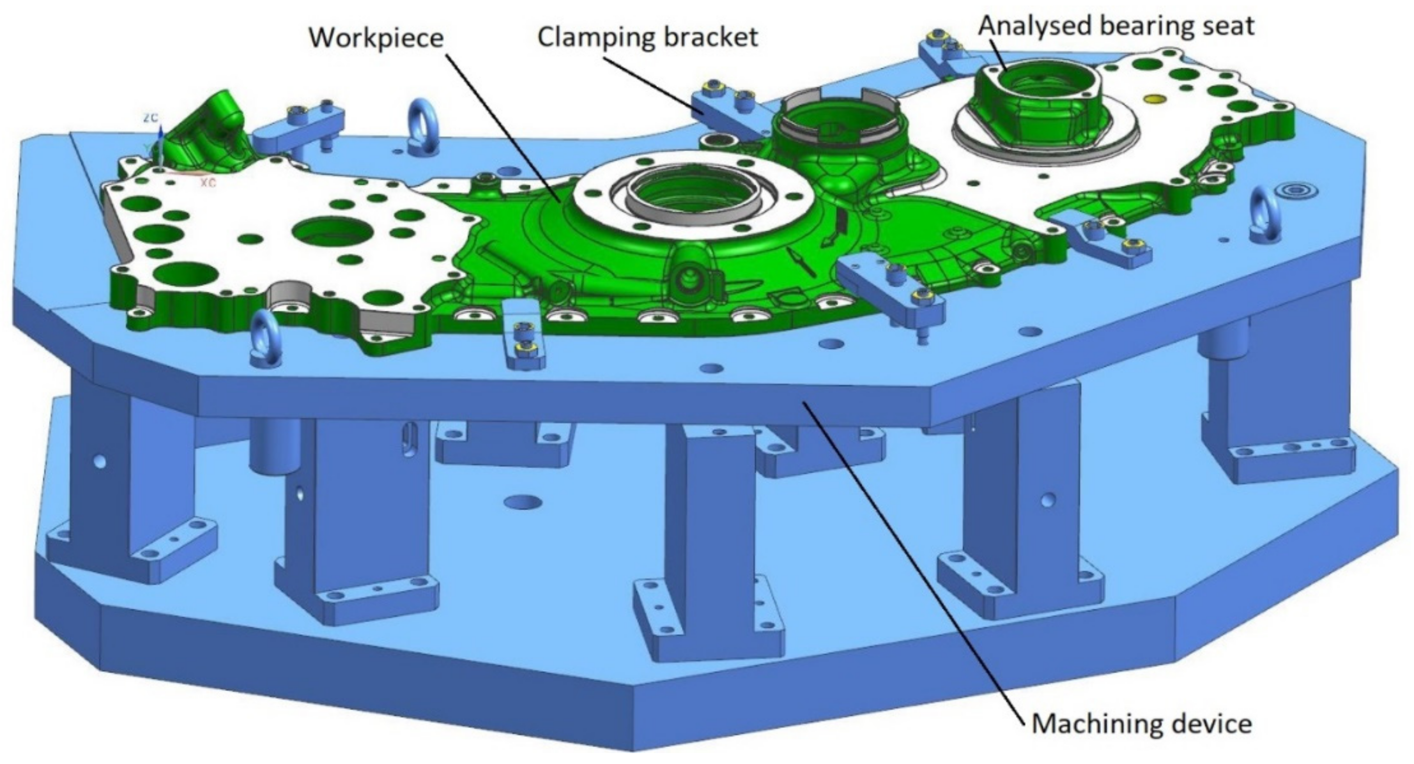
- According to design requirements, the body should be measured in a free state—it is unacceptable to use any mounting device that can introduce part deformations. During the measurement procedure on CMM, the detail is based freely on the prisms, and a plastic stabilizing mass is used to avoid displacement of the detail. However, on the CNC machine tool the ADT body is in a mounted state in the machining device (Figure 4) and the clamping forces resulting from the clamping of the mounting elements of the device act on it.
- The influence of stresses released as a result of removal of the allowance and introduced during machining causes the shape of the body in the mounted state to be different from that in the free state.
- Measurement of the body in the free state on the CMM takes place in the Central Measurement Laboratory (CML) at a stable temperature of 20 °C and relative air humidity of 45%, which is in practice impossible to achieve when measuring on a CNC machine. On a machining station, the casing is in a humid environment resulting from the use of coolants, and the ambient temperature is stable and reproducible but different from the required 20 °C.
For these reasons, it is not possible to prepare a reliable measurement report based solely on data collected on the CNC machine tool. As shown in Figure 3b, it is possible to use models based on characteristics collected on CMM and CNC machine. These models can take forms based on artificial intelligence methods, for example artificial neural networks (ANN) or fuzzy logic.
3.1. Properties of Neuro-Fuzzy Models
The features of ANNs are, among others [11]:
- The ability to learn non-linear mappings based on a data set;
- Generalizing properties;
- Tolerance for faults and noisy data.
The main drawback is that ANNs are so-called black boxes that generate output from input data. The ANN parameters cannot be interpreted in any way. In turn, fuzzy systems [12] give the possibility of a clear representation of knowledge in the form of inference rules, and the ability to act on the basis of imprecise input data, including data in linguistic rather than numerical form. As shown in [13,14,15], a fuzzy system can be transformed into the structure of ANN, which results in a so-called adaptive neuro-fuzzy inference system (ANFIS), which combines the advantages of ANN and fuzzy systems. It is then possible to learn nonlinear mappings on the basis of a data set, and at the same time, a clear representation of knowledge in the form of an inference rule base is obtained. In an ANFIS system, the parameters of premises and conclusions are subject to learning. Thanks to the generalizing properties of such a system and a clear representation of knowledge, one can build an inference model based on a relatively small set of experimental learning data.
3.2. Experimental Studies
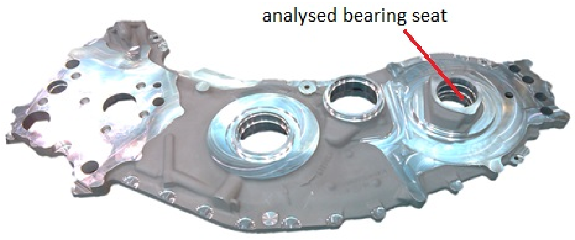
For the construction of neuro-fuzzy models, it is necessary to obtain data from the actual process of manufacturing transmissions. To carry out the experiments and obtain measurement data, a part of the ADT body shown in Figure 5 and Figure 6 was selected. It is the cover subjected to a mechanical machining operation.
The features of the selected workpiece are as follows:
- Semi-finished product—sand and mold casting;
- Residual casting stress in the semi-product;
- Technological allowance removed in the operation is up to 3 mm;
- Minimum thickness after processing is 5 mm;
- Deformations of the reference surface after machining operations amount to 0.6 mm.
Before the workpiece was machined, the accuracy of the CNC machine was verified using the standard ballbar test according to ISO 230-4 [16]. All geometrical errors were within the manufacturer’s tolerances accepted for a new machine. The Renishaw RMP600 (Renishaw plc., New Mills, UK) strain gauge in the machine’s equipment was used to measure the workpiece on the machine tool. Before machining, the probe was calibrated using the setting ring and the Renishaw calibration procedure. A test verifying the correctness of the measurement with the datum sphere was carried out for the probe calibrated in this way. This consisted of the following operations: taking the probe from the tool, measuring the height in the Z axis of the machine tool, measuring the sphere diameter with the approach in the X, Y and Z axes, returning the probe to the magazine. The test was repeated 10 times. The maximum measurement error from 10 measurements was 0.3 micrometers.
Next, 25 units of covers were machined along with the measurement of selected dimensional characteristics. The process was carried out on an Okuma MU6300V five-axis machining center (OKUMA Corporation, Oguchi-cho, Japan) in an automatic cycle without interfering with the cutting parameters, machine configuration, mounting method or measurement method.
The aim of the measurements was to obtain experimental data necessary to build learning and testing sets for the neuro-fuzzy system. After the operation, the accuracy of the machine was verified again. There was no significant change in the value of geometrical errors of the machine tool. All of the values were again within the manufacturer’s tolerances accepted for a new machine.
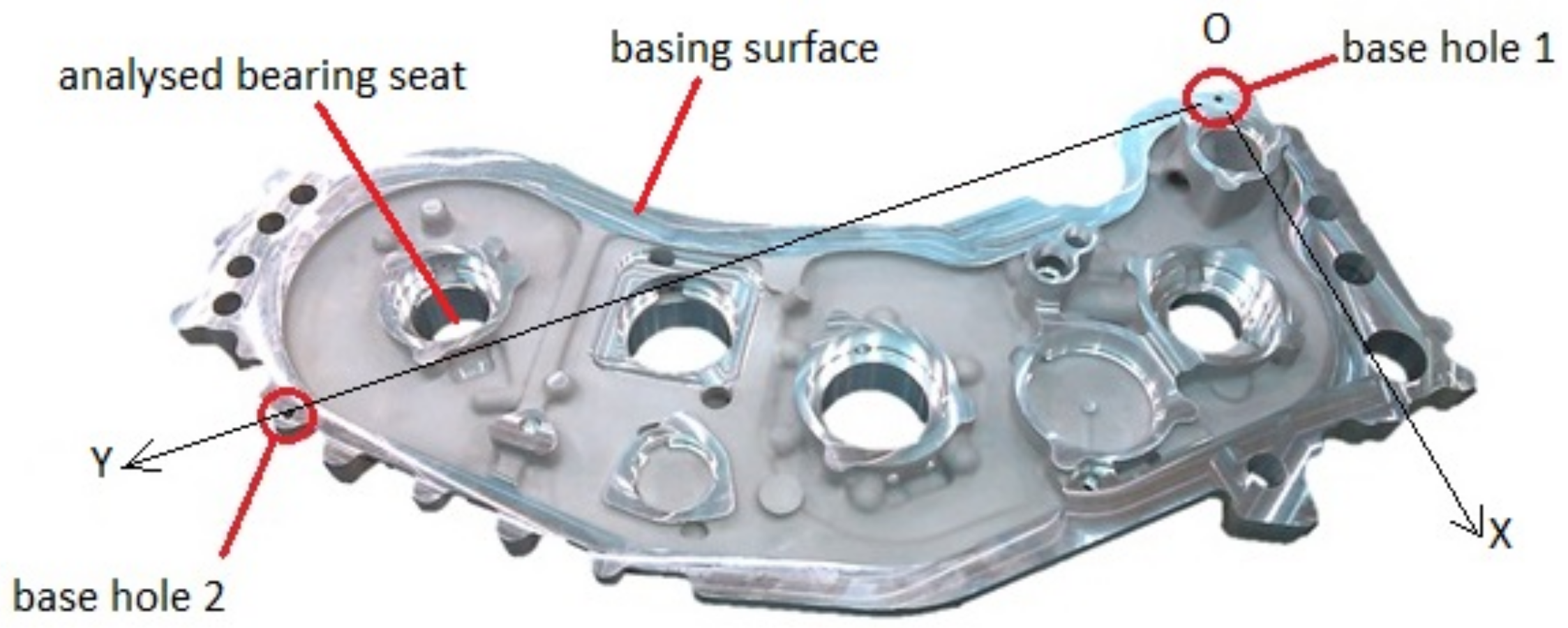
The measuring base for cover was determined based on the position of two holes made during the machining operation (hole diameter 6.5 mm, made with a tolerance of +0.015 mm) (Figure 6). In the center of base hole 1, the origin of the coordinate system (point O) was placed, while the center of base hole 2 was used to determine the orientation of the coordinate system. The drawing shows the X and Y axes. The third axis is perpendicular to them and selected in such a way that the XYZ system is clockwise. The measurement program implemented on a CNC machine only applies to the position of the bearing seat under investigation but uses the same measurement methodology as the corresponding fragment of the entire measurement program on CMM. This applies to both the adopted measurement base, the number of measurement points, their distribution and the order of measurements.
The reference measurement of the covers was then carried out in the factory CML in accordance with the standard measurement procedure approved in production technology. These dimensional and shape characteristics are a reference point for the new measurement procedure developed. A Mitutoyo CMM with a Revo2 revolution head and Modus 1.7 measuring software was used for the measurement.
In order to clearly interpret the research results, a number of assumptions were made, the most important of which are:
- The material used for testing is homogeneous, and any changes in its physical and chemical properties do not affect the measurement results;
- The change in ambient temperature during experimental tests on the CNC machine is negligible and does not affect the value of the obtained results;
- The way of fixing the workpiece to be machined using a CNC machine is repeatable and does not imply measurement errors;
- The method of mounting the workpiece to be measured using a CMM is repeatable and does not imply measurement errors;
- The thermal conditions of processing and measurements of individual workpieces are similar.
The adoption of such simplifying assumptions allows us to limit the number of variables on the basis of which the neuro-fuzzy model is built.
3.3. Case Study—Bearing Seat
One of the holes of the bearing seat, shown in Figure 7, was selected to present measurement data, research methodology and the results of work. To determine the curvature of the base face, measurements were taken at 65 points spaced evenly on the base surface (Figure 7a). To determine the position of the axis and the diameter of the hole, the coordinates of four measurement points were used, arranged in one plane every 90 degrees on the inner cylindrical surface of the bearing seat (Figure 7b). The hole axis position error was determined as the difference between the nominal position (point B) and the position resulting from the measurement (point A). Hole position deviation is the distance between points A and B. The methodology described relates to measurement on CNC and CMM.
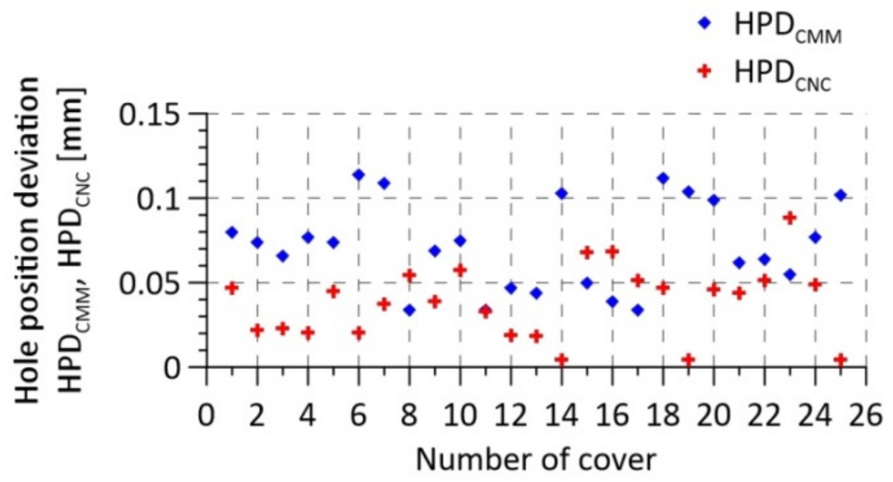
As variables for learning neuro-fuzzy models for the presented bearing seat, the following geometric parameters were measured on a CNC machine tool and in a measurement laboratory using CMM:
- Hole (bearing seat) position deviation (HPDCMM)—measurement on the CMM in a free state;
- Hole (bearing seat) position deviation (HPDCNC)—measurement on the CNC machine in the mounted state;
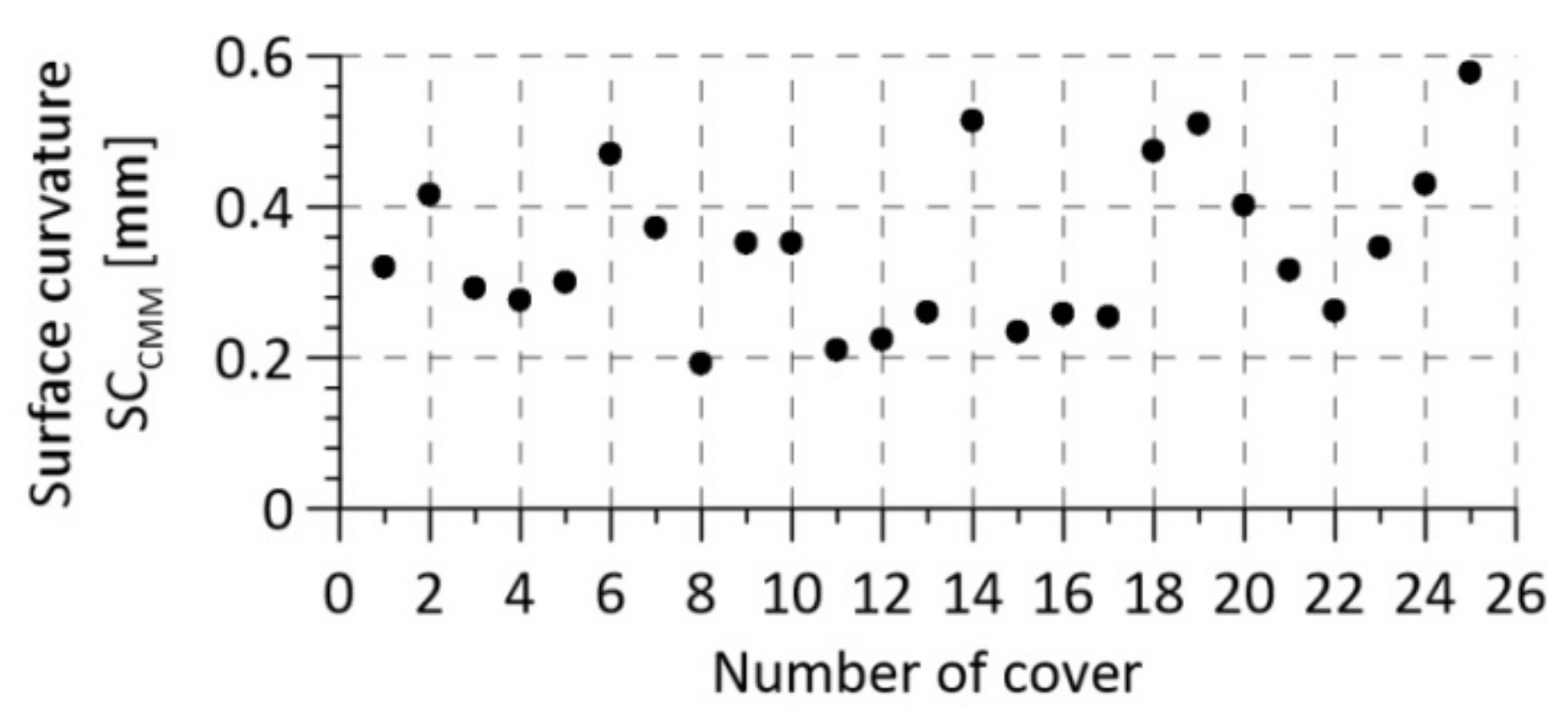
- Curvature of the reference surface of the cover (SCCMM)—measurement only on CMM in a free state.
The following results were obtained as shown in Table 1 and Figure 8 and Figure 9. The tolerance of the hole position is 0.25 mm.
This selection of features determining the position of the bearing seat was chosen as a result of preliminary tests. Their results are summarized in Section 4.1, where the data analysis is described.
4. Solution to the Problem
4.1. Data Analysis
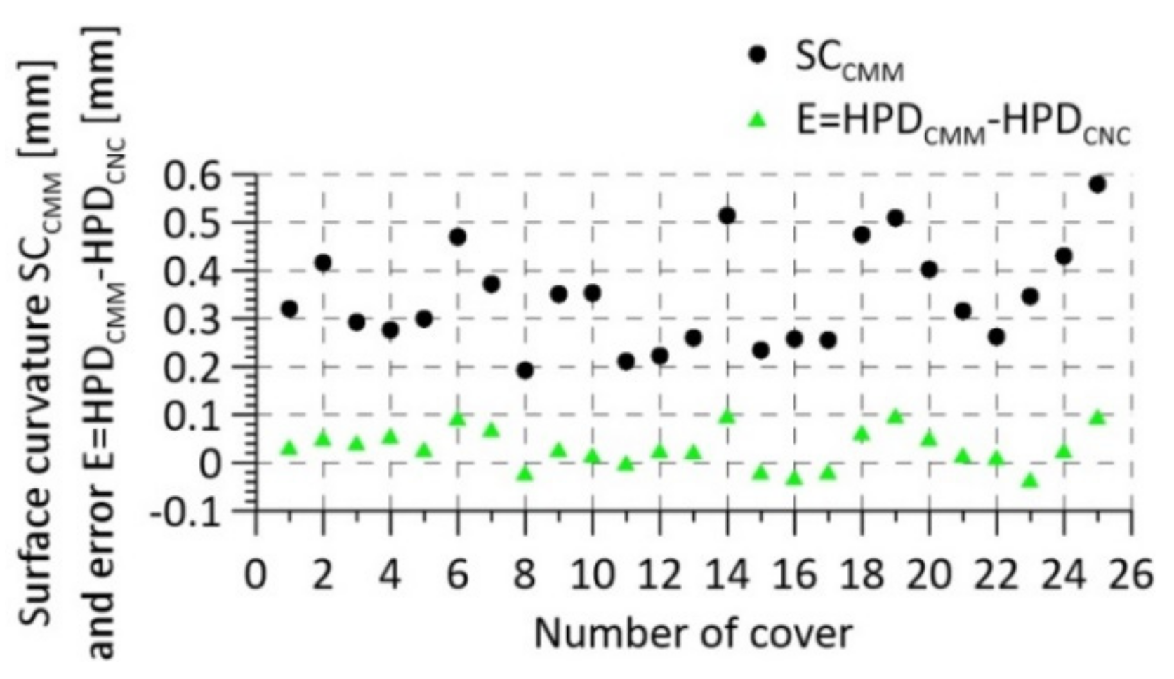
The difference between the HPDCMM and HPDCNC deviations, i.e., the measurement difference E = HPDCMM − HPDCNC, was calculated for the data from Figure 8 referring to the bearing seat deviations measured on the CMM and CNC machine. Then, these values were compared with data defining the curvatures of the reference surfaces of the covers. The results are shown in Figure 10.
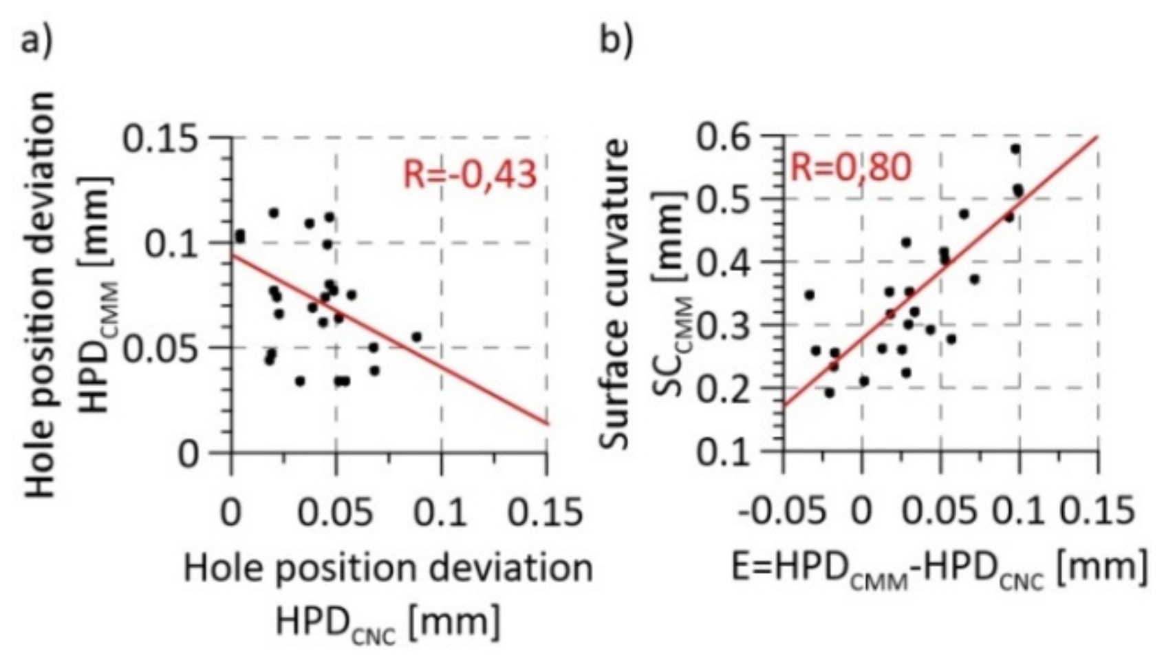
In the next stage of data analysis, the correlation of hole position deviations determined from measurements made on the CMM and CNC machine was calculated (Figure 11a). The Pearson correlation coefficient value for the HPDCMM and HPDCNC variables was determined, which is R = –0.43 and corresponds to a moderate correlation. This means that the results of measurements on the CNC machine do not reflect the results of measurements on the CMM well. A correlation was also determined between the curvature of the reference surface of the cover and the difference in deviations determined on the CMM and CNC machine (E = HPDCMM – HPDCNC) (Figure 11b). The value of Pearson’s correlation coefficient then amounted to R = 0.8, which corresponds to a very high correlation.
The analysis of the linear correlation shows that the results of measurements on the CNC machine are not very reliable because they are not strongly correlated with the results of measurements on the CMM. There is, however, a very strong relationship between the differences of measurements on CMM and CNC machine (E) and the curvature of the reference surface of the cover. The greater the curvature of the cover, the greater the difference E. This relation is explained by the fact that the measurement in the state mounted on the CNC machine is all the less reliable, the greater the curvature of the cover in an unmounted state during measurement on the CMM. The conclusion is that the results of measurements on the CNC machine together with the results of the surface curvature measurement can be used to determine the actual deviation of the hole position without measuring this parameter on the CMM.
The presented measurement data were selected as a result of preliminary tests. The quality of the neuro-fuzzy systems with two and three inputs was tested. The system with two inputs was based on the surface curvature measured on CMM (SCCMM) with the deviation of the position of the hole measured on the CNC (HPDCNC), i.e., data presented in Table 1. The system with three inputs additionally included the height of the bearing seat face, measured on a CNC machine. It turned out that the introduction of the third input adversely affected the size of the model error. As a result of the data tests, no correlation of the variable determining the height of the bearing seat face with the remaining data was found. This is due to the fact that the face of the bearing seat is made with greater dimensional tolerance than the other analyzed features and there is a greater variance of the measurement data. This resulted in a deterioration of the results generated by the neuro-fuzzy model with three inputs. Thus, finally a model based on two input variables was used.
4.2. Application of Neuro-Fuzzy Models to Determine Bearing Seat Position Deviation
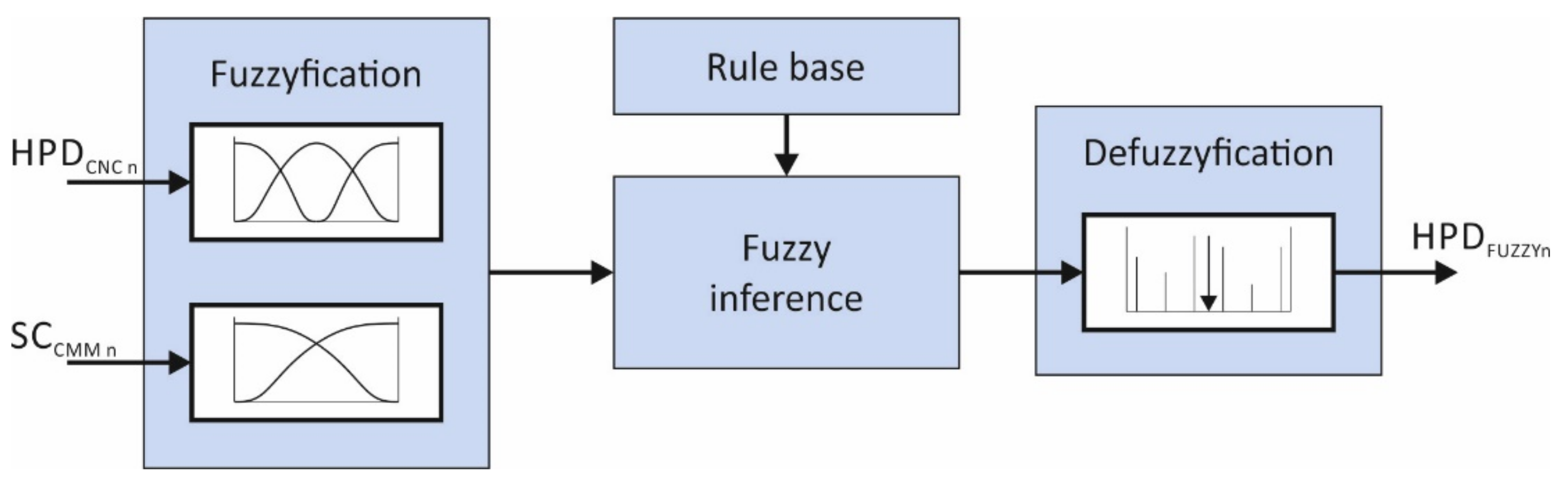
In order to determine the deviation of the bearing seat of the ADT body a neuro-fuzzy system was used. The MATLAB environment in the R2018b version and the Neuro-Fuzzy Designer application were used in the research. The structure of the system is shown in Figure 12.
The Takagi-Sugeno fuzzy model with two inputs and one output was chosen. The input variables were: normalized hole position deviation measured on the CNC machine (HPDCNCn) and normalized cover surface curvature measured on the CMM (SCCMMn), and the output variable was HPDFUZZYn, which after the learning process was to map the normalized hole position deviation measured on the CMM (HPDCMMn).
The input and output data were linearly normalized by the min-max method, according to the formula:
where is the measurement data vector with elements , , is the value of the i-th element of the measurement data vector after normalization, and are the smallest and largest elements of the vector , and and are the limits of the normalization interval. Due to the values of the measurement data, and were adopted.
From thusly normalized measurement data, five sets of learning data and five sets of test data were created, which were used to check the quality of the neuro-fuzzy neural learning process. The first set was prepared in such a way that 20% of the results were allocated to the test set and the remaining ones to the learning set. Subsequent sets were prepared similarly, with no element from a given test set being repeated in another test set. Then, preliminary testing was carried out, based on which the type and number of membership functions for each variable were selected. Finally, the input functions assumed membership functions in the form of asymmetrical Gaussian curves (three for the HPDCNCn variable and two for the SCCMMn variable), and for the HPDCMMn output variable, the so-called singletons (fixed values) were in the amount of six. A database of rules (Equation (2)) regarding the form was created, in which both the parameters of premises and conclusions, in other words the parameters of the membership function of input variables (parameters of the Gauss function) and the values of singletons, were subjected to learning. The name inimfj means the j-th function of the i-th input, and outimfj denotes the j-th membership function of the i-th output variable. The variables in the rule database Equation (2) are normalized variables.
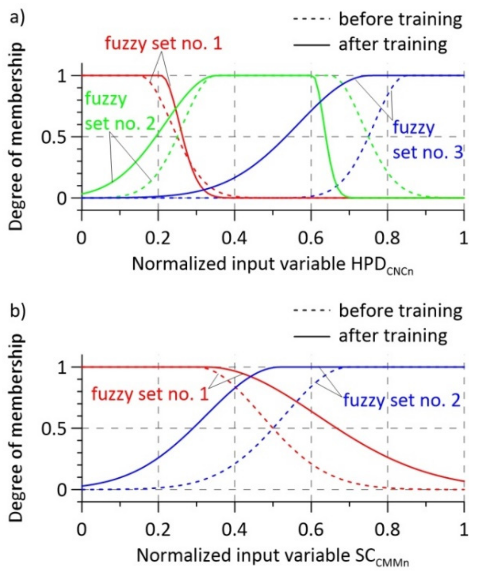
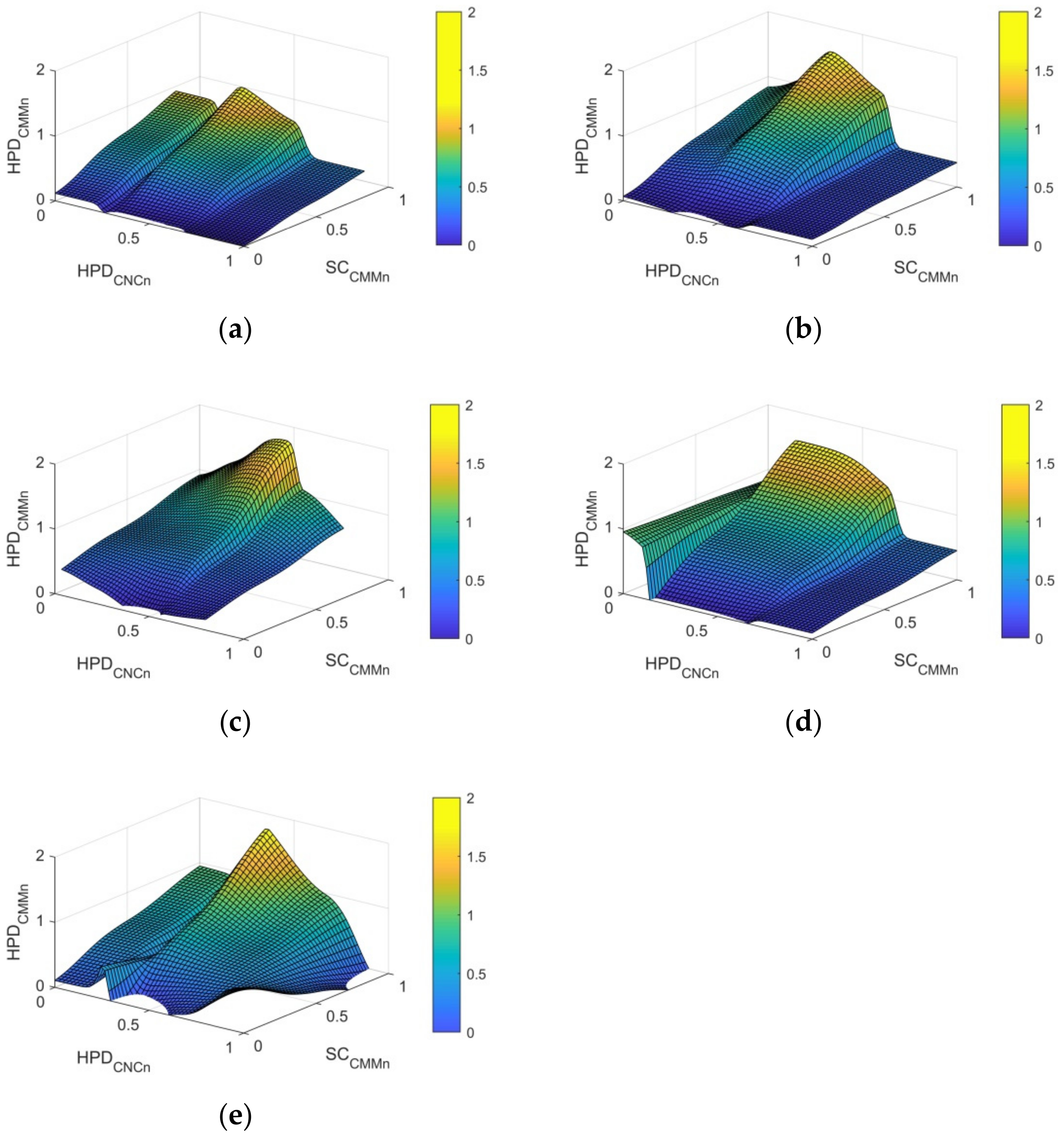
The learning process was carried out for five sets of learning and test data. Membership functions for input variables before and after the learning process for the second learning set are shown in Figure 13, while the singleton output values are shown in Table 2. Figure 14 shows the surfaces of neuro-fuzzy models after the learning process for all five learning sets. Table 3 presents the results generated by neuro-fuzzy models (HPDFUZZY) for appropriate test sets containing data that were not presented in the learning process of individual systems. HPDFUZZY values are values after denormalization, for which Equation (1) was used. Errors of fuzzy models were determined in relation to the results of measurements on CMM according to the following formula:
and the maximum error δmax of each model was calculated (Table 3).
4.3. Discussion of Results
The model surfaces shown in Table 3 are similar in nature. Differences in their shape result from differences in the learning data sets. This is reflected in the maximum error values δmax of each model, which range from 0.0139 mm for model 1 to 0.0275 mm for model 5. Nevertheless, the maximum error of model 5 of 0.0275 mm is about an order of magnitude less than the position tolerance of the bearing seat, which is 0.25 mm. Taking into account that the deviations of the hole position shown in Figure 8 do not exceed half of the tolerance range, it can be concluded that the sum of the workpiece production errors and the errors of neuro-fuzzy models does not exceed the required manufacturing tolerance.
5. Summary
The article presents the concept of quality control of manufactured aircraft parts on the example of one selected feature. The key issue under consideration was the possibility of replacing the CMM in selected measuring operation with a CNC machine, which was to enable a reduction in the load on the measuring laboratory. The problem is presented for a selected component, which was the cover of the ADT. Detailed analysis, calculations and modelling of the dependencies between the measurement data were carried out for the selected key geometric characteristic, i.e., the bearing seat position deviation. The obtained results are acceptable from the point of view of quality control, because the sum of the bearing seat position production error and the error of determining its position using a neuro-fuzzy model based on data from CNC machine and CMM is within the desired production tolerance.
The analyzed cover of the ADT body has four bearing seats made to the same tolerance. The results of analyses regarding the remaining bearing seats are not presented in the article due to their similarity to the case considered in the work. It should only be noted that the input data for neuro-fuzzy models formulated for the remaining bearing seats are the data obtained on the CNC machine and the same measurement data regarding the reference surface curvature of the cover obtained on the CMM. We can see here the advantage of the proposed approach, in which for a given cover of five measurements, four of them are carried out on a CNC machine (hole deviation) and only one on CMM (surface curvature). In addition, in the production cycle, other dimensional characteristics are prepared for the body cover, for which the manufacturing tolerances are similar to those for the bearing seats. Thus, it is possible to implement the concept of quality control shown in Figure 3b. Applying to the other characteristics an approach analogous to the control of deviations of bearing seats a situation can be achieved where the number of measurement characteristics, k, determined on the CMM is much smaller than all of the necessary characteristics, m. However, for other geometric parameters it may turn out, that the model may be much more complicated and include more than two correlated characteristics and the neuro-fuzzy model will be more extensive. Further work will focus on attempts at hardware implementation of the obtained solutions in industrial conditions and on trying to formulate neuro-fuzzy models for other dimensional characteristics.
Author Contributions
G.B. contributed to the conceptualization and investigation; P.G. contributed to the methodology and founding acquisition; P.G. and G.B. contributed to writing of this paper.
Funding
This project is financed by the Minister of Science and Higher Education of the Republic of Poland within the “Regional Initiative of Excellence” program for years 2019–2022. Project number 027/RID/2018/19, amount granted 11,999,900 PLN.
Conflicts of Interest
The authors declare no conflict of interest. The funders had no role in the design of the study; in the collection, analyses, or interpretation of data; in the writing of the manuscript; or in the decision to publish the results.
References
- Holub, M.; Jankovych, R.; Andrs, O.; Kolibal, Z. Capability assessment of CNC machining centres as measuring devices. Measurement 2018, 118, 52–60. [Google Scholar] [CrossRef]
- Zhao, F.; Xu, X.; Xie, S.Q. Computer-aided inspection planning—The state of the art. Comput. Ind. 2009, 60, 453–466. [Google Scholar] [CrossRef]
- Zhao, F.; Xu, X.; Xie, S. STEP-NC enabled on-line inspection in support of closed-loop machining. Robot. Comput. Integr. Manuf. 2006, 24, 200–216. [Google Scholar] [CrossRef]
- Wang, H.; Zhou, M.X.; Zheng, W.Z.; Shi, Z.B.; Li, H.W. 3D machining allowance analysis method for the large thin-walled aerospace component. Int. J. Precis. Eng. Manuf. 2017, 18, 399–406. [Google Scholar] [CrossRef]
- Smith, S.; Wilhelm, R.; Dutterer, B.; Cherukuri, H.; Goel, G. Sacrificial structure preforms for thin part machining. CIRP Ann. 2012, 61, 379–382. [Google Scholar] [CrossRef] [Green Version]
- Zhang, X.; Yu, T.; Wang, W.; Ehmann, K.F. Three-dimensional process stability prediction of thin-walled workpiece in milling operation. Mach. Sci. Technol. 2016, 20, 406–424. [Google Scholar] [CrossRef]
- Burghardt, A.; Kurc, K.; Szybicki, D.; Muszyńska, M.; Szczęch, T. Robot-operated inspection of aircraft engine turbine rotor guide vane segment geometry. Teh. Vjesn. Tech. Gaz. 2017, 24 (Suppl. S2), 345–348. [Google Scholar] [CrossRef]
- Kurc, K.; Burghardt, A.; Gierlak, P.; Szybicki, D. Non-contact Robotic Measurement of Jet Engine Components with 3D Optical Scanner and UTT Method. In Lecture Notes in Electrical Engineering, Proceedings of the Methods and Techniques of Signal Processing in Physical Measurements, Rzeszów-Arłamów, Poland, 17–20 September; Hanus, R., Mazur, D., Kreischer, C., Eds.; Springer: Cham, Switzerland, 2018; Volume 548, pp. 151–164. [Google Scholar] [CrossRef]
- Liu, C.; Jin, S.; Lai, X.; He, B.; Li, F. Influence of complex structure on the shrinkage of part in investment casting process. Int. J. Adv. Manuf. Technol. 2015, 77, 1191–1203. [Google Scholar] [CrossRef]
- Matras, A.; Plaza, M. The FEM simulation of the thin walled aircraft engine corpus deformation during milling. In Photonics Applications in Astronomy, Communications, Industry, and High-Energy Physics Experiments; International Society for Optics and Photonics: Bellingham, WA, USA, 2016; Volume 10031, p. 100310B. [Google Scholar] [CrossRef]
- Gurney, K. An Introduction to Neural Networks; CRC Press: Boca Raton, FL, USA, 2014. [Google Scholar]
- Nguyen, H.T.; Walker, C.L.; Walker, E.A. A First Course in Fuzzy Logic; CRC Press: Boca Raton, FL, USA, 2018. [Google Scholar]
- Li, H.X.; Chen, C.P. The equivalence between fuzzy logic systems and feedforward neural networks. IEEE Trans. Neural Netw. 2000, 11, 356–365. [Google Scholar] [CrossRef] [PubMed]
- Jang, J.S.; Sun, C.T. Functional equivalence between radial basis function networks and fuzzy inference systems. IEEE Trans. Neural Netw. 1993, 4, 156–159. [Google Scholar] [CrossRef] [PubMed]
- Buckley, J.J.; Hayashi, Y.; Czogala, E. On the equivalence of neural nets and fuzzy expert systems. Fuzzy Sets Syst. 1993, 53, 129–134. [Google Scholar] [CrossRef]
- International Organization for Standardization, ISO 230-4:2005(E). Test Code for Machine Tools—Part 4: Circular Tests for Numerically Controlled Machine Tools; International Organization for Standardization: Geneva, Switzerland, 1 April 2005. [Google Scholar]
Figure 1.
Aircraft engine with accessory gear (ADT).

Figure 2.
Coordinate Measuring Machine (CMM).

Figure 3.
Quality control of production: (a) carried out entirely in the measurement laboratory; (b) carried out in a large part on the production line.
Figure 3.
Quality control of production: (a) carried out entirely in the measurement laboratory; (b) carried out in a large part on the production line.

Figure 4.
Accessory drive train (ADT) cover mounted in the machining device.

Figure 5.
Tested workpiece after the machining operation—top view (machined surfaces visible as lighter).
Figure 5.
Tested workpiece after the machining operation—top view (machined surfaces visible as lighter).

Figure 6.
Base face of the cover (on the circumference) constituting the measuring reference surface—bottom view.
Figure 6.
Base face of the cover (on the circumference) constituting the measuring reference surface—bottom view.

Figure 7.
Cover after machining with distribution of measuring points. (a) Base face of the cover with marked measuring points used to determine the curvature of the surface. (b) Bearing seat with four measuring points used to determine, among others, the center of the hole (point A). Point B is the nominal position of the hole. Hole position deviation is the distance between points A and B.

Figure 8.
Deviations of the hole position.

Figure 9.
Curvature of the reference surface of the cover.

Figure 10.
Curvature of the reference surface of the cover in combination with the difference of measurement results on CMM and CNC machine.
Figure 10.
Curvature of the reference surface of the cover in combination with the difference of measurement results on CMM and CNC machine.

Figure 11.
Correlation of measurement data: (a) hole position deviation; (b) surface curvature.

Figure 12.
Diagram of the neuro-fuzzy system.

Figure 13.
Membership functions before and after the learning process: (a) for the first input variable; (b) for the second input variable. Dashed lines refer to the shape of the set before the training phase; solid lines refer the shape of the set after the training phase.
Figure 13.
Membership functions before and after the learning process: (a) for the first input variable; (b) for the second input variable. Dashed lines refer to the shape of the set before the training phase; solid lines refer the shape of the set after the training phase.

Figure 14.
Surfaces of neuro-fuzzy models after the learning process for five learning sets. (a) Surface of model 1 for the first set of learning data. (b) Surface of model 2 for the second set of learning data. (c) Surface of model 3 for the third set of learning data. (d) Surface of model 4 for the fourth set of learning data. (e) Surface of model 5 for the fifth set of learning data. The color represents the value of the HDPCMMn variable. Model surfaces refer to normalized variables, therefore there are no length units on the axes.


Table 1.
Data from measurement systems.
| Body Number | Hole Position Deviation Measured on CMM HPDCMM/mm | Hole Position Deviation Measured on CNC Machine HPDCNC/mm | Curvature of the Cover Reference Surface Measured on CMM SCCMM/mm |
|---|---|---|---|
| 1 | 0.080 | 0.0468 | 0.3210 |
| 2 | 0.074 | 0.0219 | 0.4160 |
| 3 | 0.066 | 0.0227 | 0.2920 |
| 4 | 0.077 | 0.0204 | 0.2770 |
| 5 | 0.074 | 0.0447 | 0.3010 |
| 6 | 0.114 | 0.0205 | 0.4700 |
| 7 | 0.109 | 0.0374 | 0.3720 |
| 8 | 0.034 | 0.0544 | 0.1930 |
| 9 | 0.069 | 0.0389 | 0.3520 |
| 10 | 0.075 | 0.0574 | 0.3530 |
| 11 | 0.034 | 0.0328 | 0.2110 |
| 12 | 0.047 | 0.0191 | 0.2240 |
| 13 | 0.044 | 0.0185 | 0.2610 |
| 14 | 0.103 | 0.0044 | 0.5150 |
| 15 | 0.050 | 0.0680 | 0.2340 |
| 16 | 0.039 | 0.0685 | 0.2590 |
| 17 | 0.034 | 0.0515 | 0.2550 |
| 18 | 0.112 | 0.0470 | 0.4750 |
| 19 | 0.104 | 0.0044 | 0.5110 |
| 20 | 0.099 | 0.0460 | 0.4020 |
| 21 | 0.062 | 0.0439 | 0.3170 |
| 22 | 0.064 | 0.0515 | 0.2620 |
| 23 | 0.055 | 0.0884 | 0.3470 |
| 24 | 0.077 | 0.0490 | 0.4310 |
| 25 | 0.102 | 0.0044 | 0.5790 |
Table 2.
The values of singletons.
| Singleton Number | 1 | 2 | 3 | 4 | 5 | 6 |
|---|---|---|---|---|---|---|
| Value before training | 0 | 0 | 0 | 0 | 0 | 0 |
| Value after training | 0.04974 | 0.8634 | −0.1123 | 1.87 | 0.09989 | 0.3944 |
Table 3.
Test results of neuro-fuzzy models.
| Number of the Tested Model | Variable | Value mm | ||||
|---|---|---|---|---|---|---|
| Model 1 | HPDCMM | 0.0740 | 0.0750 | 0.0500 | 0.0990 | 0.1020 |
| HPDFUZZY | 0.0660 | 0.0724 | 0.0384 | 0.0877 | 0.1159 | |
| 0.0080 | 0.0026 | 0.0116 | 0.0113 | 0.0139 | ||
| 0.0139 | ||||||
| Model 2 | HPDCMM | 0.0770 | 0.0690 | 0.1030 | 0.1040 | 0.0770 |
| HPDFUZZY | 0.0557 | 0.0927 | 0.0936 | 0.0930 | 0.1017 | |
| 0.0213 | 0.0237 | 0.0094 | 0.0110 | 0.0247 | ||
| 0.0247 | ||||||
| Model 3 | HPDCMM | 0.0660 | 0.0340 | 0.0440 | 0.1120 | 0.0550 |
| HPDFUZZY | 0.0699 | 0.0329 | 0.0625 | 0.1171 | 0.0532 | |
| 0.0039 | 0.0011 | 0.0185 | 0.0051 | 0.0018 | ||
| 0.0185 | ||||||
| Model 4 | HPDCMM | 0.0740 | 0.1090 | 0.0470 | 0.0340 | 0.0640 |
| HPDFUZZY | 0.0934 | 0.0832 | 0.0407 | 0.0523 | 0.0545 | |
| 0.0194 | 0.0258 | 0.0063 | 0.0183 | 0.0095 | ||
| 0.0258 | ||||||
| Model 5 | HPDCMM | 0.0800 | 0.1140 | 0.0340 | 0.0390 | 0.0620 |
| HPDFUZZY | 0.0727 | 0.0865 | 0.0142 | 0.0574 | 0.0723 | |
| 0.0073 | 0.0275 | 0.0198 | 0.0184 | 0.0103 | ||
| 0.0275 | ||||||
© 2019 by the authors. Licensee MDPI, Basel, Switzerland. This article is an open access article distributed under the terms and conditions of the Creative Commons Attribution (CC BY) license (http://creativecommons.org/licenses/by/4.0/).
Share and Cite
MDPI and ACS Style
Bomba, G.; Gierlak, P. Dimensional Control of Aircraft Transmission Bodies Using CNC Machines and Neuro-Fuzzy Systems. Appl. Sci. 2019, 9, 4094. https://doi.org/10.3390/app9194094
AMA Style
Bomba G, Gierlak P. Dimensional Control of Aircraft Transmission Bodies Using CNC Machines and Neuro-Fuzzy Systems. Applied Sciences. 2019; 9(19):4094. https://doi.org/10.3390/app9194094
Chicago/Turabian StyleBomba, Grzegorz, and Piotr Gierlak. 2019. "Dimensional Control of Aircraft Transmission Bodies Using CNC Machines and Neuro-Fuzzy Systems" Applied Sciences 9, no. 19: 4094. https://doi.org/10.3390/app9194094
Note that from the first issue of 2016, this journal uses article numbers instead of page numbers. See further details here.