The PLC as a Smart Service in Industry 4.0 Production Systems †

1
Faculty of Electrical Engineering & Information Technoloigy, Hochschule Duesseldorf University of Applied Sciences, 40476 Duesseldorf, Germany
2
Fraunhofer Institute for Embedded Systems and Communication Technologies ESK, 80686 Munich, Germany
*
Author to whom correspondence should be addressed.
†
This paper is an extended version of paper published in the 14th International Conference on Remote Engineering and Virtual Instrumentation, NY, USA 15–17 March 2017.
Appl. Sci. 2019, 9(18), 3815; https://doi.org/10.3390/app9183815
Submission received: 17 July 2019
/
Revised: 5 September 2019
/
Accepted: 6 September 2019
/
Published: 11 September 2019
(This article belongs to the Special Issue New Industry 4.0 Advances in Industrial IoT and Visual Computing for Manufacturing Processes)
Abstract
:Industrial controls, and in particular, Programmable Logic controllers (PLC) currently form an important technological basis for the automation of industrial processes. Even in the age of industry 4.0 and industrial internet, it can be assumed that these controllers will continue to be required to a considerable extent for the production of tomorrow. However, the controllers must fulfill a range of additional requirements, resulting from the new production conditions. Thereby, the introduction of the service paradigm plays an important role. This paper presents the concept of smart industrial control services (SICS) as a new type of a PLC. As a distributed service-oriented control system in an IP network, a SICS controller can replace the traditional PLC for applications with uncritical timing in terms of Industry 4.0. The SICS are programmed as usual in industry, according to the standard IEC 61131-3, and run in a SICS runtime on a server or in a cloud. The term Smart Service is introduced and the uses of SICS as a smart service, including a clearing system for the creation of new business models based on control as a service, are described. As a result, two different SICS prototype implementations are described and two application examples from manufacturing automation, as well as the evaluation of the real-time features and the engineering of a SICS controller, are discussed in the paper.
1. Introduction
Industrial controls, and in particular, PLC controllers currently form an important technological basis for the automation of industrial processes. Even in the age of industry 4.0 (I40) and industrial internet, it can be assumed that these controllers will continue to be required to a considerable extent for the production of tomorrow. However, the controllers must fulfill a range of additional requirements, resulting from the new production conditions.
When applying Industry 4.0 principles [1], high-quality networked production systems result, based on cyber physical systems (CPS), also referred to as cyber physical production systems (CPPS). A series of I40 requirements are placed on the future controllers used in these systems. These include:
- Introduction of the service paradigm in production automation (production services);
- Autonomy, reconfigurability and agility (plug and work);
- Overcoming the strict information encapsulation of controllers;
- Networking in local and global networks;
- Interoperability between heterogeneous control systems;
- Dependencies are to be changeable dynamically at runtime;
- Use of models for the development of “higher-quality” control approaches;
- Orchestration of heterogeneous controllers.
Current PLC controllers cannot yet fulfill the majority of these requirements or can only do so on a rudimentary basis or at extremely high expense.
The paper describes the concept and two prototype implementations for a new type of a PLC controller in which the controller functions (control programs) will be implemented as smart control services in a cloud. The programming of this new PLC occurs as is usual in industry, pursuant to the standard IEC 61131-3.
2. State-of-the-Art
Resulting from the historical development of PLC controllers, they have been developed as proprietary device systems that are operated locally under real-time conditions. If a networking of these controllers is necessary from a user viewpoint, proprietary protocols that operate on top of TCP/IP or standardized protocols, such as Modbus TCP, Profinet, etc., are used for this. The standard technologies widespread from the Internet and Web have so far hardly played any role for PLC controllers.
For a number of years, however, a transformation has been underway, with PLC manufacturers increasingly integrating Information and Communication (IC) technologies from the web in their systems, such as web server and HTML pages for diagnosis and configuration, in order to adapt the controllers incrementally to the new requirements.
Four different approaches to make PLC controllers I40 compatible can essentially be revealed from state-of-the-art technologies. These include the introduction of basic web technologies, the global networking of process data, the introduction of service principles and the virtualization of PLCs.
2.1. Introduction of Basic Web Technologies
Most of the newer PLC controllers already contain a web server and special HTML pages on the device—enabling a browser-based configuration and diagnosis of the controller. Process data or program variables form the control program and can be read, sometimes also written, with restrictions. The solutions are proprietary and adapted to the relevant controller. Open and consistent web interfaces are not available. The above I40 requirements cannot, therefore, be fulfilled.
2.2. Global Networking of Process Data
For integration of the PLC controllers in supervising, management and coordination systems (e.g., SCADA or MES systems), which are partly based on web technologies, additional modules are integrated in the PLC controllers, enabling a bidirectional and event-based process data transmission between the controller, supervisor and management system. Those include solutions such as the web connector with the MQTT broker in WAGO controllers [2], or access to controllers that already contain an OPC UA server (e.g., Siemens PLC S7-1500).
These solutions also involve proprietary and closed control-integrated modules. Although the modules utilize web technologies, they cannot be transferred to other controllers. The global process data communication is used for HMIs (human machine interfaces) and/or supervisor and coordination functions in the higher level of the automation hierarchy (e.g., plant management level). Authoritative statements regarding the time response of the process data transmission are not available. However, different statements result from the reaction times (latencies) of 200 to 500 ms, or greater. Open and consistent web interfaces are not available. The above I40 requirements can only partly be fulfilled, sometimes with high adaptation expenses for integration into a CPPS.
2.3. Introduction of Service Principles
Based on the I40 requirement for the service capability of an I40 controller, some projects [3,4] are involved with the integration of service functions in PLC controllers. Thus, the Device Protocol for Web Services (DPWS) enables, as standardized protocol, service-based access to PLC controllers [5] also for reading/writing process data. The internal functional system of a PLC is to be equipped correspondingly for that, with the support of the controller’s manufacturer.
However, the DPWS solutions have a principle disadvantage: Instead of reducing or removing the information encapsulation (I40 requirement), further functionalities (service functions) are encapsulated in the controller. Moreover, DPWS uses the very heavy-duty and complex Microsoft web service protocols. The attainable transmission time of process data via a global network, therefore, tend to be in the upper range. It is difficult to obtain any definite data.
2.4. Virtualisation of PLCs
Current R&D work deals with the virtualization of complete PLC controllers and their outsourcing into the cloud. A scalable control platform for cyber-physical systems in industrial productions is researched and realized in [6]. In [7], a cloud-based controller is presented, which also uses a virtual control system in an Infrastructure as a Service (IaaS) cloud. The work of [8] also uses virtualized PLC controls in the cloud and connects these to OPC UA-based automation devices using web technologies.
Problems with the virtualization of PLCs result especially from the fact that already available manufacturer-specific PLCs are virtualized. These controllers, however, are closed systems, which were originally not developed considering the aspects of web technologies. Adjustments, modifications or extensions of these controllers by third parties are hardly possible. Functionality cannot be resolved as services. The flexibility of virtualization is very limited.
Reference [9] proposed a methodology for converting an automation plant managed by PLCs onto an EFSM control module (EFSM—extended finite state machine) that is driven by single board computers or SoC (system-on-a-chip). The EFSM Control Module can use IoT devices, but in that solution, the functionality (control program) cannot be resolved as a service from the cloud.
In summary, it can be estimated that there are different solutions and efforts to equip PLC controllers with additional functions in order to be able to use the controllers in an Industry 4.0-type IP network. To this end, the known work already uses web technologies in part, in a manufacturer specific and/or limited way, and increasingly also tries to use the service principle and cloud structures as a new paradigm for the realization of control functions. However, there are still the following deficits that result in corresponding needs for research:
- Although web technologies are used, a flexible distribution of the structure and function of the control functionality is not used. The information encapsulation of industrial control programs in local or virtualized devices (PLCs) is not called into question.
- For smart control services using cloud technologies as an essential feature of a future networked industry, systematic investigations, architectures, interfaces and demonstration solutions are lacking.
- Available standard technologies from the world of IP networks for increasing flexibility and efficiency are not or insufficiently used in the control level.
3. Concept for a Smart Control Service
The following section describes the concept of a smart control service and introduces the basic model of a SICS.
3.1. Control Classification
To assess the I40 capabilities of a PLC controller, categories were introduced which divide an industrial controller according to its abilities: service ability (SA) and control locality (CL). The properties are divided according to class C (Controller) = <SA><CL>. With the proposed methodology, I40 control classes can be defined and structural configurations for a PLC as a smart industrial control service (SICS) can be indicated (Table 1).
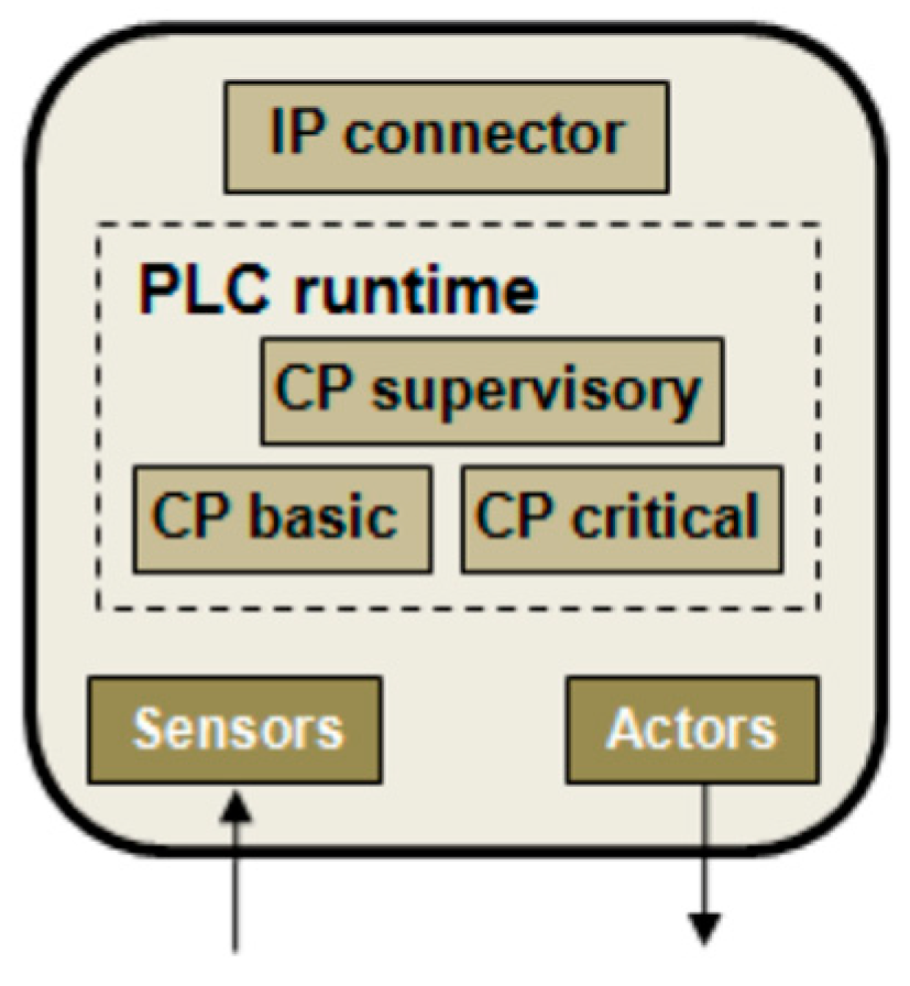
Looking at a PLC as a CPS component, the traditional IEC 61131 control program (CP) can be divided into three parts:
- Basic functional program part (CP basic—CPb);
- A program part which performs superior, administrative and/or user interface functions (CP supervisory—CPs);
- Critical part of the program regarding real-time and security (CP critical—CPc).
In order to evaluate the I40 capabilities of a PLC or a control system, this 3-part structuring of the control program is used. Figure 1 shows the structure of such a PLC.
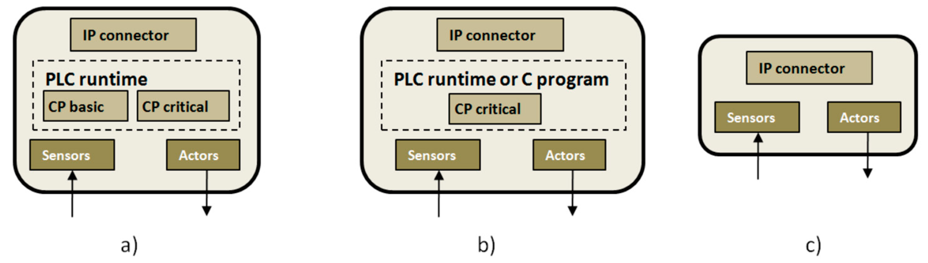
If the control system, as shown in Figure 1, is used as the basis, and modified as a result of the increasing displacement of the control programs into a cloud as services, it leads to the evolution of a PLC as a CPS component Industrial Control, as shown in Figure 2.
Three types of CPS components (Figure 2) are produced according to the aforementioned disassembly of the PLC program into three parts:
- (a)
- The controller hardware only implements the program components CPb and CPc. The traditional runtime environment of a PLC is still required.
- (b)
- For safety reasons, only the CPc program parts are implemented in the controller hardware. The classic PLC runtime machine can be used but this is not mandatory. The implementation of the CPc could also be carried out with specific embedded program parts (e.g., in C).
- (c)
- The controller hardware no longer contains a control part, but only sensors and actuators. All control programs are distributed as smart services in the network.
The Service Ability considers the ability of a controller to utilize control functionalities (control programs) as services. According to Table 1, the program parts CPb, CPs and CPc can be distributed unequally. In a class C11 controller, for example, the uncritical and overlapping functionalities (CPs) are not located on the local PLC hardware, but distributed on other systems in the network (corresponds to a traditional, distributed control system). However, part of the control programs could also be used as a service from the cloud.
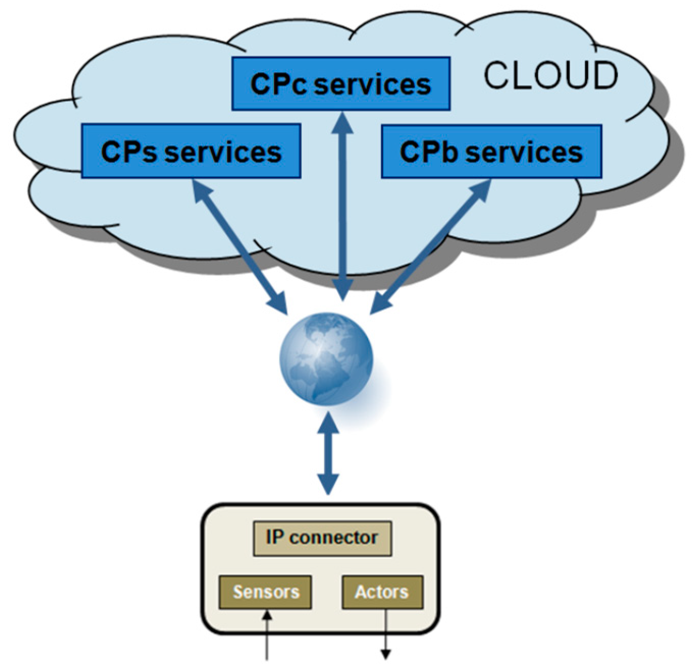
As the focus of the research is on cloud-based control services, work is focused on C3x controllers, in particular C33 (Figure 3). With this I40 control class, the complete control program, with all program parts (including the PLC runtime), is outsourced as services to a cloud or to any server in the network. The control hardware consists only of sensors and actuators connected to an IP network (see Figure 2, type c).
If one realizes C3x controllers, such as the C33 controller, according to Figure 3 via smart services (see Section 4.3), such a control system could be referred to as a smart industrial control service controller, or in short, a SICS controller.
3.2. SICS Base Model
A SICS base model must take into account both the aspects of control engineering and the web technology features.
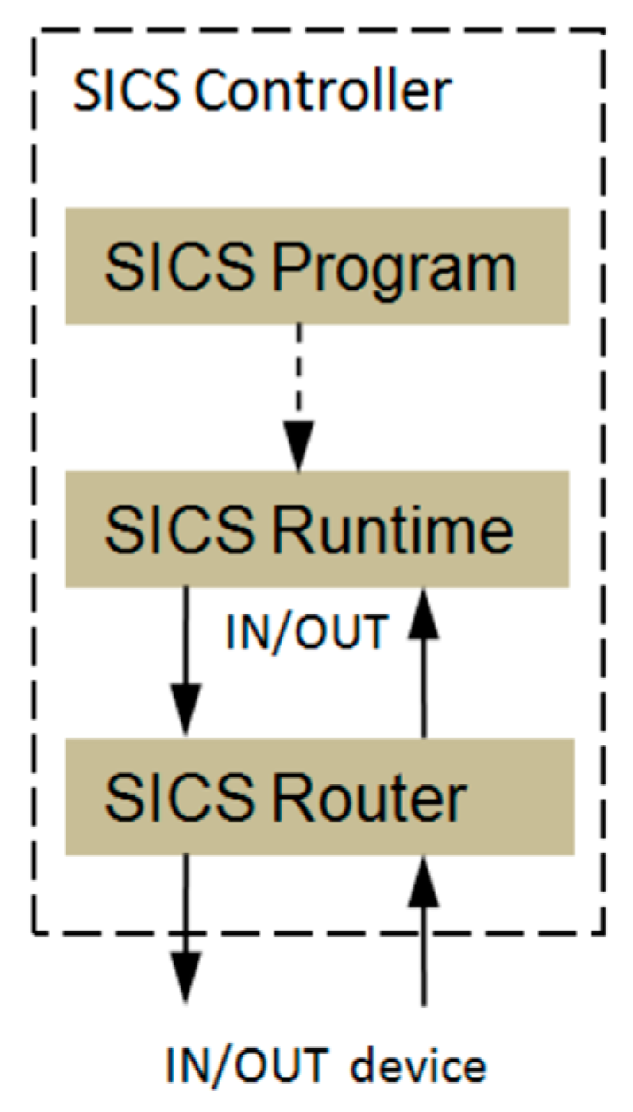
From a control engineering point of view, a SICS controller based on a traditional PLC consists of the following components (Figure 4):
- SISC program: IEC61131-3 control program in the PLCopen XML notation. It includes only the program and the variables, but not the I/O configuration.
- SICS runtime: Execution environment for the SICS program. It can be cycle controlled or event-based.
- SICS router: Device or I/O configuration for a SICS controller; i.e., it is determined which CPS components (which automation devices) are connected to the controller. Since the real devices are already virtualized in an Internet-based environment via the CPS component, a SICS configuration only includes the assignment between the absolute IN/OUT addresses in the SICS program and their assignment (routing) to the IN/OUTs of the CPS components. A SICS device configuration is, therefore, also referred to as a SICS router.
By separating of SICS program, SICS runtime and SICS router in a SICS controller, and distributing the components across an IP network using cloud technologies, it is possible to change, in real time, the control program (control algorithm). This also applies to the device configuration (e.g., for replacements of modules or plug and work). A SICS program and SICS router can be exchanged on-the-fly during one program cycle.
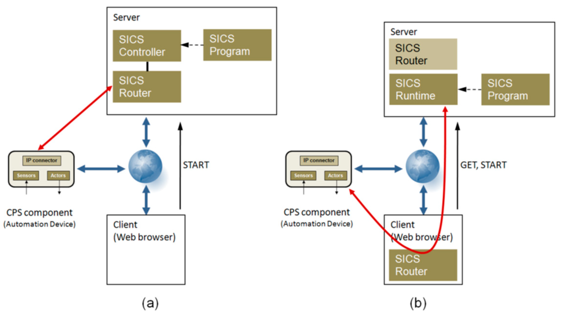
For the identification of a viable SICS basic model, it is also necessary to show possible solution variants for a SISC controller, starting with the basic principles on the web, and then to reflect those in the available web technologies. As explained in detail in [10], if the control technology based SICS structure is adapted to the web-based functional systems, four general SICS base models are obtained:
- (1)
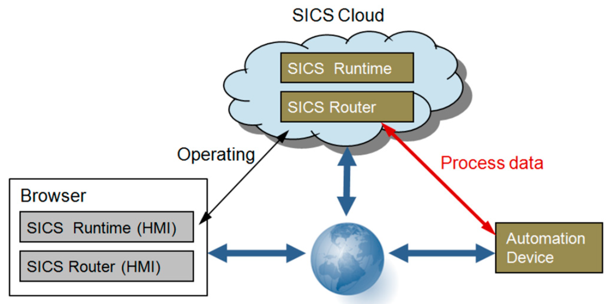
- Server mode (SM): The SICS router is linked to fixed CPS components in a configuration process. After the SICS runtime has been started via the client, the SICS router automatically connects to the associated CPS component via the IP network and the SICS runtime executes the SICS program (Figure 5a).
- (2)
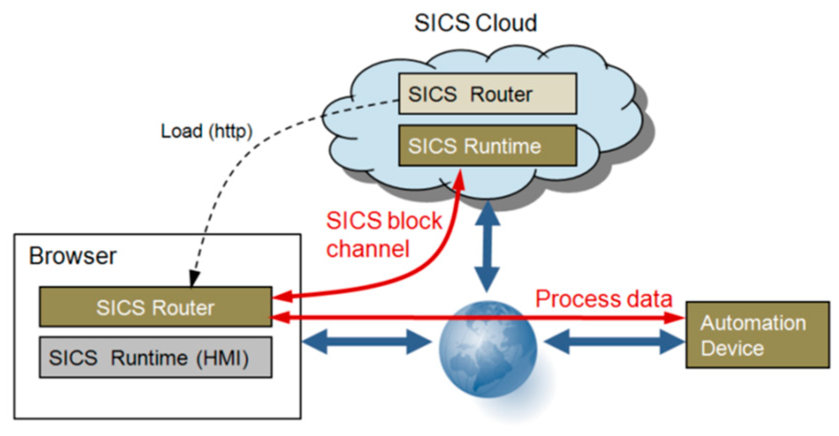
- Server-based mixed mode (SMM): Before starting the SICS runtime, a SICS router is loaded from the server to the client. After the SICS runtime is started, this router dynamically connects the CPS component with the SICS runtime on the server. All process date from the automation device are now routed to the server via the client (Figure 5b).
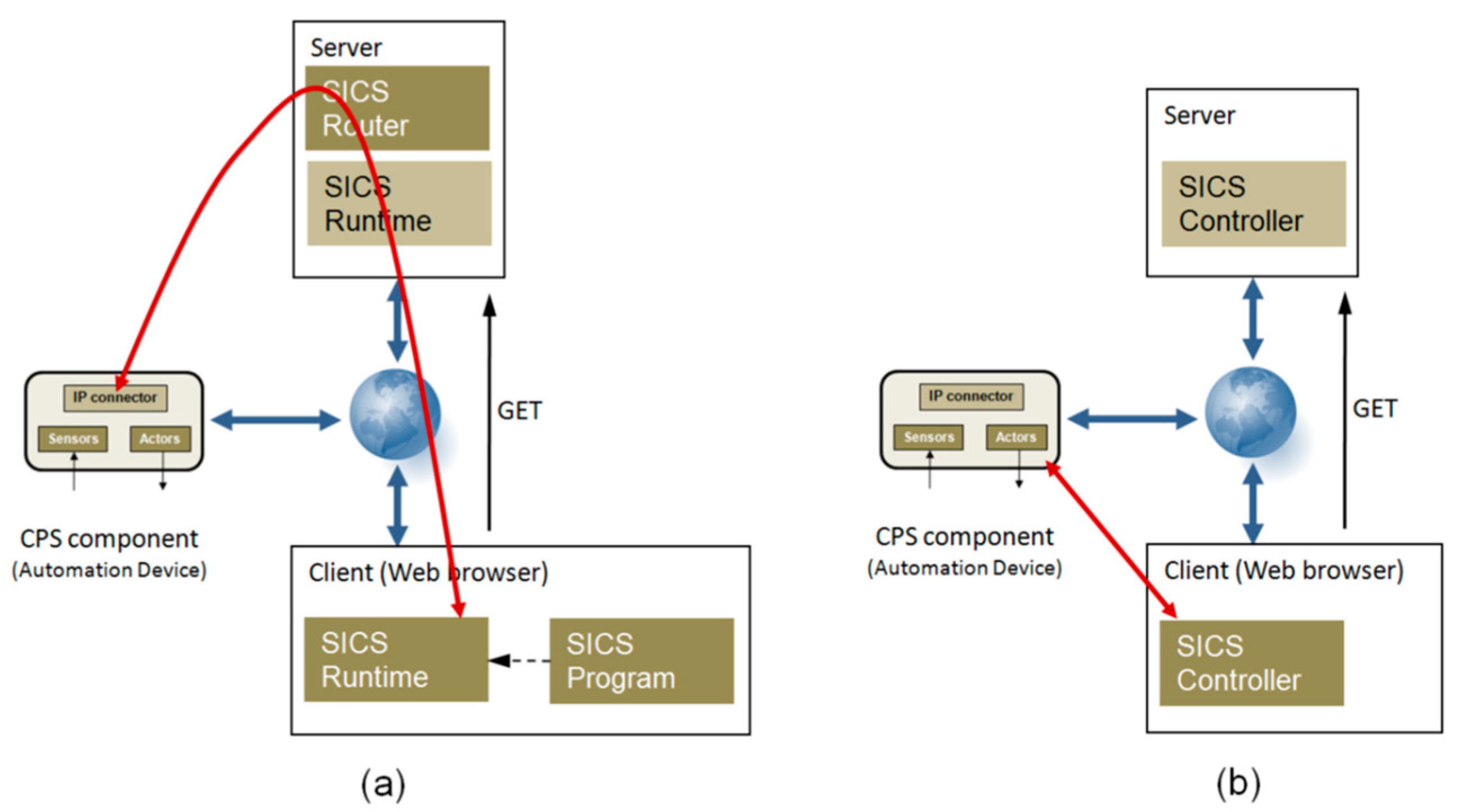
- (3)
- Client-based mixed mode (CMM): The control program runs in the SICS runtime on the client, but the communication to the CPS component runs over a configurable SICS router in the server (Figure 6a).
- (4)
- Client Mode (CM): SICS runtime and SICS routers are executed as one instance on the client (web browser). The client is an inherent part of the SICS control system and is necessarily required for executing the control program. The server is no longer required at the runtime (Figure 6b).
3.3. Control Services
The control features of a SICS controller are no longer available as classic control functions, but rather as control services according to the service paradigm. A SICS (literally: smart industrial control service) can, thereby, use all the features of cloud computing, thus enabling the creation of new business models, such as the rental of control services.
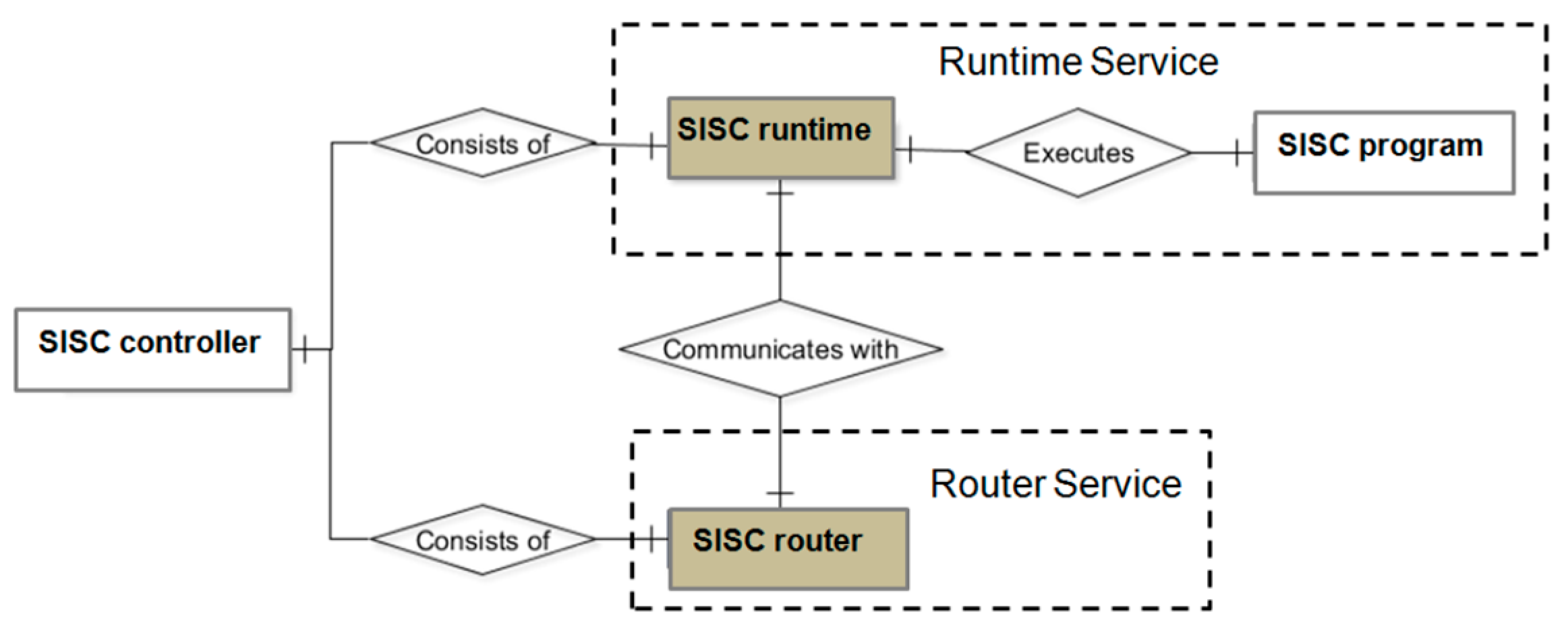
In terms of information technology, SICS has to be produced, parameterized, distributed, stored and recalled as objects by means of software methods. Since the components of a SICS controller are no longer available as hardware, but only as software objects in the IC or Internet/Intranet and generally are also stored there in databases, it makes sense to use data models for the modeling of the SICS’s service architecture. Figure 7 shows the SICS structure, for the controller depicted in Figure 4, as an entity relationship diagram (ERD).
According Figure 7 a SICS controller is realized with two services:
- Runtime service (SICS runtime or SICS RT);
- Router service (SICS router or SICS-R).
A SICS controller usually requires both services. However, it can also be realized by only a runtime service if the connected CPS component (automation device) already has a SICS runtime interface. The SICS router service is comparable to the I/O configuration part of a classical PLC.
Both SICS services are built according to the principle of web-oriented automation services (WOAS) [11].
If required, the SICS service instances can be displayed in the client (web browser) for operation and visualization. Therefore, both services include a graphical user interface (HMI proxy). Via that parameter, the HMI proxy can be switched on or off.
3.3.1. SICS Runtime
Corresponding to the state machine in a traditional PLC, the SICS runtime also has a defined sequence behavior as the most important component in order to execute a control program. A SICS-RT implements the operating states, listed in Table 2, in accordance with a PLC.
A SICS runtime can be operated in cyclic mode and event-based mode. In cycle mode, the I/O image is updated, equivalent to a traditional PLC. In event-based operation, the control program is executed only when the value of an input variable changes or an internal event occurs (for example, the execution of a timer).
3.3.2. SICS Router
The I/O configuration service of a SICS controller (SICS router) is separated from the SICS runtime for the following reasons:
- Securing a dynamic reconfiguration; i.e., in the case of an identical control program, the I/O configuration can be changed within a program cycle.
- Identical machines/systems can be operated with the same control program, despite different I/O modules.
- A distributed separate configuration service forms the basis for a future automatic IIoT-based device configuration (IIoT—industrial internet of things).
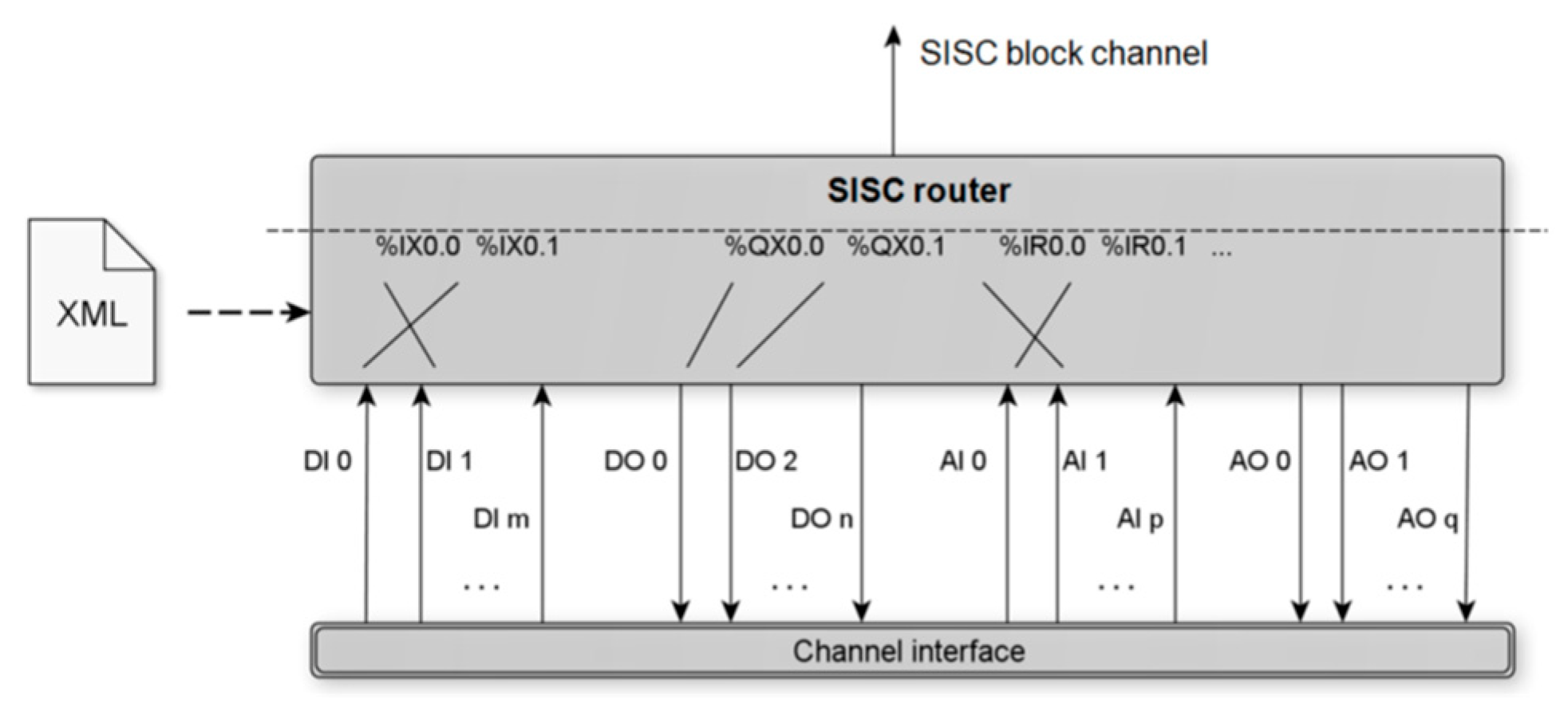
SICS routing works according to the following two principles:
- A SICS program (PLCopen XML program) works with absolute I/O addresses.
- The SICS router connects the absolute I/O addresses to the real I/O addresses of the devices (CPS components).
Figure 8 illustrates the functionality of a SICS router.
The digital and analogue inputs and outputs of a device, connected via the channel interface, are routed to absolute I/O program addresses and transferred to the SICS runtime via a SICS block channel. The routing rules (interconnection matrix) are defined via an XML file.
4. Results
To evaluate the SICS concept, three prototypical implementations were built: A SICS controller in the server mode (SM—Figure 5a), a SICS controller in the server-based mixed mode (SMM—Figure 5b) and a SICS controller in the client mode (CM—Figure 6b).
In the following, only the two SICS controllers in SMM and SM mode are considered in more detail, since these could be particularly suitable for future control applications.
4.1. SICS Controller in Server-Based Mixed Mode (SMM)
In the case of a SMM solution, the SICS runtime is executed in the server (cloud) as an instance and the SICS router in the client (browser) as an instance.
Here, as well, a direct process data communication takes place only between the client and devices. Between SICS router and SICS runtime, there is a special bidirectional block channel for the transmission of I/O images. This channel transmits the process data as strings over a secure WebSocket. The SICS runtime is operated via an HMI proxy on the client. Figure 9 illustrates the SMM solution.
In terms of technical implementation, the SICS-SMM controller is a distributed elaborate solution. However, process data connection to the devices can also be performed locally and the SICS runtime can use the full performance of the server anyway. A dynamic re-configuration is easy and possible.
Figure 10 shows the simplified implementation structure of a SICS-SMM controller at runtime.
After opening the corresponding web page in the client, a SICS-RTs instance is generated dynamically as a runtime engine in the server, and simultaneously, the corresponding control program is compiled into an executable JavaScript (JS) program by the structured text (ST) compiler in the server. This JS program is then loaded into the CICS-RTs instance.
The following instances are created dynamically in the client:
- VD instance: This instance operates as a virtual device according to [12] and connects to the CPS components (devices).
- SICS-R instance: Routes the absolute I/O addresses to the physical device addresses.
- SICS-RTc instance: Serves as an HMI proxy for the visualization/operation of the CICS-RT instance in the server.
Generally, any number of SICS-RTs instances can run in the server, each of which can work with other clients. The ST compiler works together with all SICS-RTs instances and can also be moved to another server (cloud).
Some of the advantages of the SMM solution are:
- The configuration of a SICS SMM controller can be carried out completely in an IoT or IIoT platform because all required instances (in the server and in the client) can be created and deleted via the client.
- Service-like C3x controllers can be built, because all SICS instances are available and manageable as separate service objects. The cloud model SaaS (software as a service) can be implemented.
- Different SICS routers, which can also be generated dynamically, enable a dynamic reconfiguration of the control system online without time delay. This forms the basis for adaptive and self-adaptive systems.
- SICS runtime can use the full performance and stability of the server.
A detailed description of the implementation for the SICS-SMM is documented in [13].
4.2. SICS Controller in the Server-based Mode (SM)
The SICS SMM controller always requires an active web browser (client) during runtime, as this is where I/O routing to the devices takes place. This is eliminated with the SISC-SM controller: All required service entities of a SICS controller run exclusively in the server.
Based on the general structure in Figure 5a, a SICS controller in the server-based mode (SM) is shown in Figure 11.
Process data communication takes place only between server (cloud) and devices. The client (web browser) has no influence on this communication. In the client, which is temporarily required for operating purposes, there are only HMI proxy objects for operation and visualization of the SICS runtime and router instances.
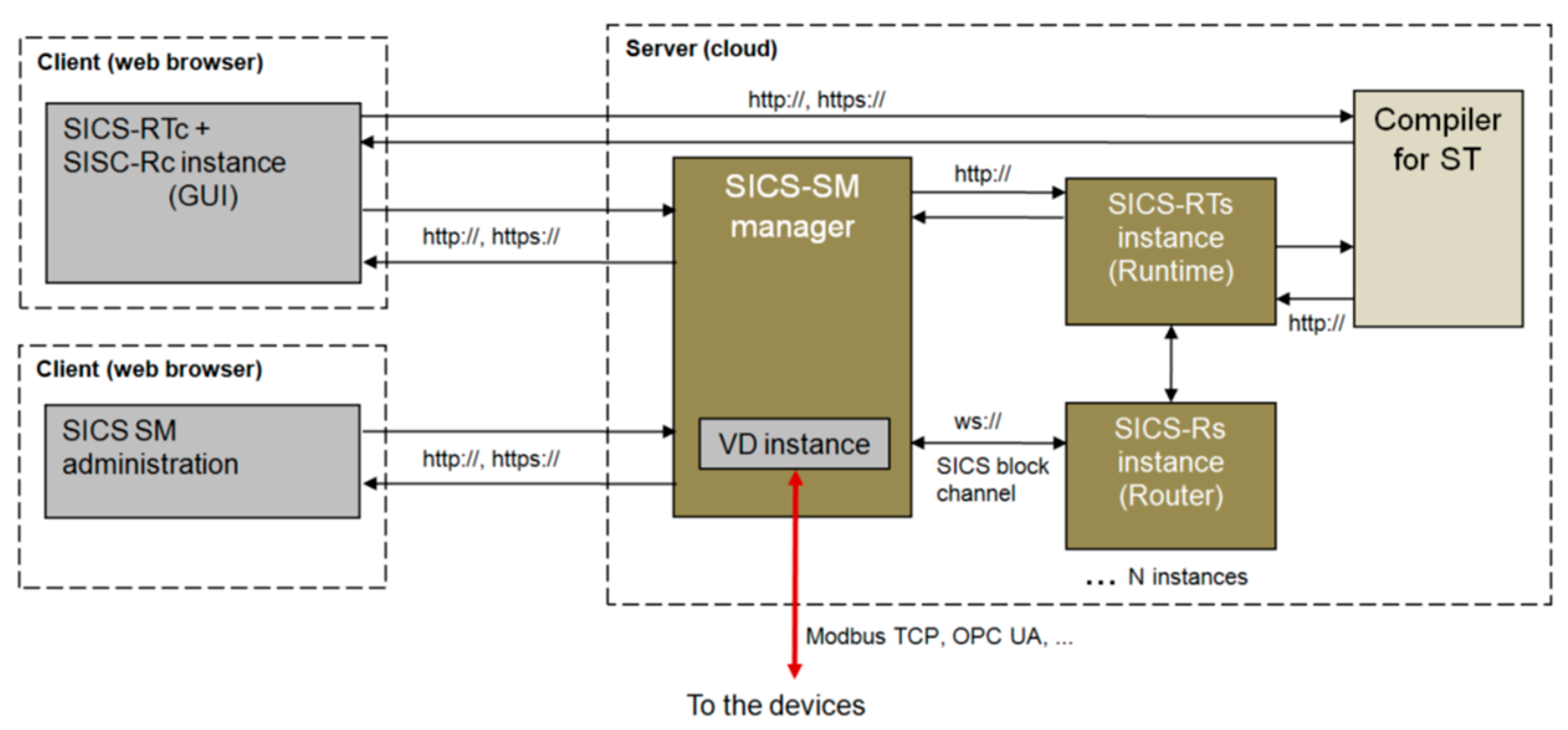
The prototype implementation is based on the SMM structure of Figure 10, and it relocates the SISC router to the server. In addition, a SISC SM manager is required in the server, via which the SISC runtime instances must be generated explicitly by means of an administration tool. The simplified implementation structure of a SISC-SM controller is shown in Figure 12. A complete description of the SISC-SM can be found in [14].
A SISC-SM controller is operated and visualized via a web page. However, this is only temporary if necessary for monitoring the control. The SISC controller runs independently in the server or in a cloud after startup. As with the SICS-SMM solution, any number of SISC controller instances can be distributed on any servers, e.g., also running on the local network via Edge or Fog computing.
Some advantages of the SM solution are:
- Controllers can run as software instances independent of web browsers distributed on any server system.
- Communication to the devices may be via any TCP protocols (e.g., Modbus TCP or OPC UA), as far as is supported by the servers. The devices do not need a web-enabled communication.
- Different SICS router instances enable dynamic reconfiguration of the control system online without delay.
- The SICS runtime can use the full performance and stability of the server.
However, the prototype implementation still has a few disadvantages:
- The configuration of a SICS-SM controller cannot yet be realized completely via an IoT or IIoT platform. There is still a need for an additional administration tool.
- It is basically possible to set up C3x controllers as a smart service, since all SICS-SM instances are also available and manageable as separate service objects. However, the complete SaaS model (software as a service) is much more difficult to implement than in a SISC-SMM solution. Therefore, an implementation is not yet available.
4.3. PLC as a Smart Service
The SISC controllers described in the previous two sections as a new kind of PLC in the Industry 4.0 era make sense only if the controllers available as services can now also be handled, managed and billed as a smart service.
According to [15], smart services are characterized by the following properties:
- Connection to a technically suitable service infrastructure (e.g., IoT or IIoT platform or cloud system).
- Efficiency for the end customer directly or indirectly with the help of a service provider.
- Transparency, disclosure and constant discourse with the users.
Thus, according to those characteristics, a management and execution environment (middleware) is required with which to configure and operate a SICS control system. This could be, e.g., a web-based SCADA system, a cloud system or an IoT or IIoT system, which is provided by a third party as a provider.
The IoT platform FlexIOT (http://www.flexiot.de) is used as middleware for the two example implementations. This IoT platform FlexIOT is based on the research results of the project WOAS [16] and provides a flexible, extensible and easy-to-use kit for the IoT and IIoT. With FlexIOT, SICS controllers can be designed as web-based, and connected and operated with other automation services (HMI, SCADA, etc.).
4.4. Clearing of SICS Services
If you want to offer PLC functions as smart services or control as a service (CaaS) in the context of a business model, you have to create interfaces and make them transparent and open, in order to give third-parties the opportunity to connect their business models to these interfaces
In the IC Industry, this has already been standard for some years and is being used with a strong upward trend. In the classical automation industry, these service models are so far largely unknown or, for various reasons, difficult to implement or even unwanted.
What does this look like for PLCs as smart services, according to the SICS concept?
- The PLC functionality as a service with disclosed and well-defined interfaces is available with the SICS controllers.
- A third party may integrate and offer the SISC services in his cloud system or IoT system (e.g., FlexIOT).
- For implementation as a business model, however, the SICS services must now also be able to be settled appropriately.
The implementation of topic 3 requires special consideration, since previous SaaS systems (including various IoT platforms) charge IC services very differently.
For automation services (control systems, HMI, SCADA, alarm monitoring, etc.), business models make sense from the point of view of future globalized, convertible and digitized production, which can bill individual services on a runtime basis. Since machines and stations normally are not permanently operated with all available functionalities, a billing after runtime significantly improves the cost-efficiency of the user, and also ensures a cost transparency of the services used.
So far, the authors, however, do not know a system in which automation services can be billed on runtime basis. Most billing is done with a flat rate and/or according to the number of integrated devices and/or transmitted data volume. One reason for this is certainly that on one hand, in the usual server-centered systems a customer and service-specific runtime determination within the server is very expensive and on the other hand, the runtime of services in the field of IC plays rather a subordinate role.
For the settlement of the SICS services, a clearing system has therefore, been developed for the FlexIOT platform (FlexIOT Service Portal) with which the service’s runtime can be determined and settled, at least for a SICS SMM controller.
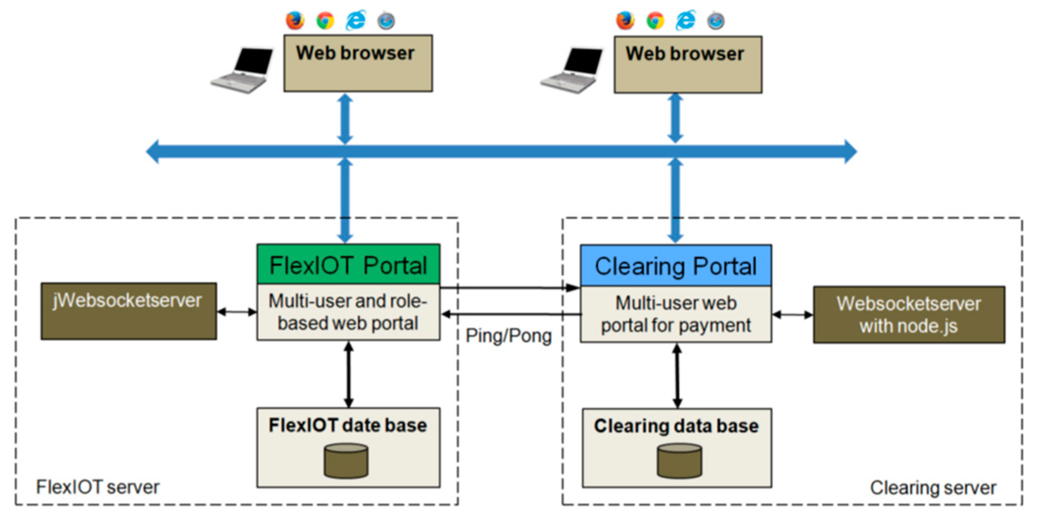
The clearing system runs independently of the FlexIOT portal and uses its own database for the billing data. Figure 13 illustrates the basic structure of the interaction between the FlexIOT portal and the clearing system.
In RUN mode of the FlexIOT portal, i.e., if a user uses a configured FlexIOT functional system (for example, a SICS control function or an HMI panel), the runtime measurement of the FlexIOT services in the clearing system takes place via a ping-pong mechanism. The services can be analyzed in detail in the clearing portal and settled via PayPal. Detailed information about the clearing of described smart services, you can find in [17]. The clearing portal can be tested online on http://www.flexiot.de:3000 and uses the same user accounts as the FlexIOT portal.
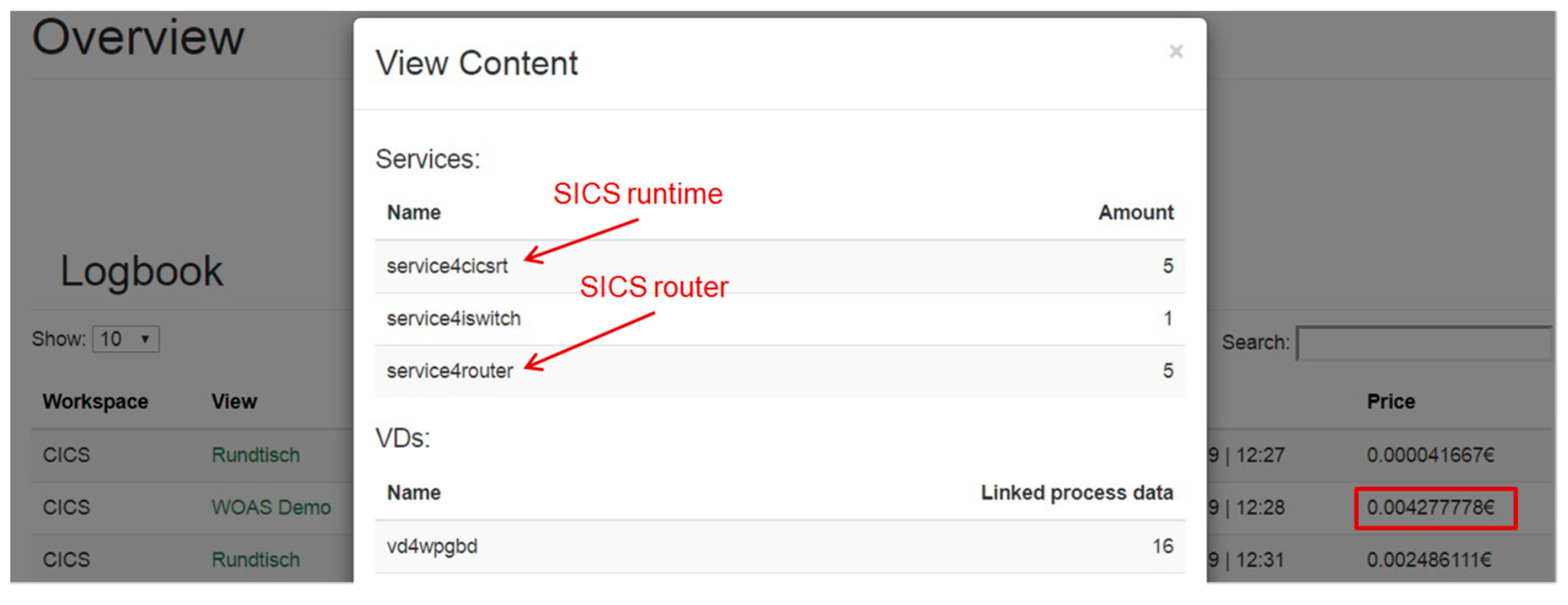
Figure 14 shows a part of the billing/analysis webpage in the clearing system for a sample project of a user in which 5 SICS-SMM controller instances were used for several minutes. A total of 106 process datums from an automated station were connected to the SISC controllers.
5. Discussion
The control programs for the SISC-SMM and SICS-SM prototype were created with the programming system CoDeSys from 3S in the language ST and exported as PLCopen XML programs for execution in the SICS runtime. The connection of the I/Os of the automation devices occurs via WebSocket/OPC or MQTT/Modbus TCP.
In the following, an application example for a SICS-SM and a SICS-SMM will be discussed.
5.1. Application Examples of a SICS-SM Controller
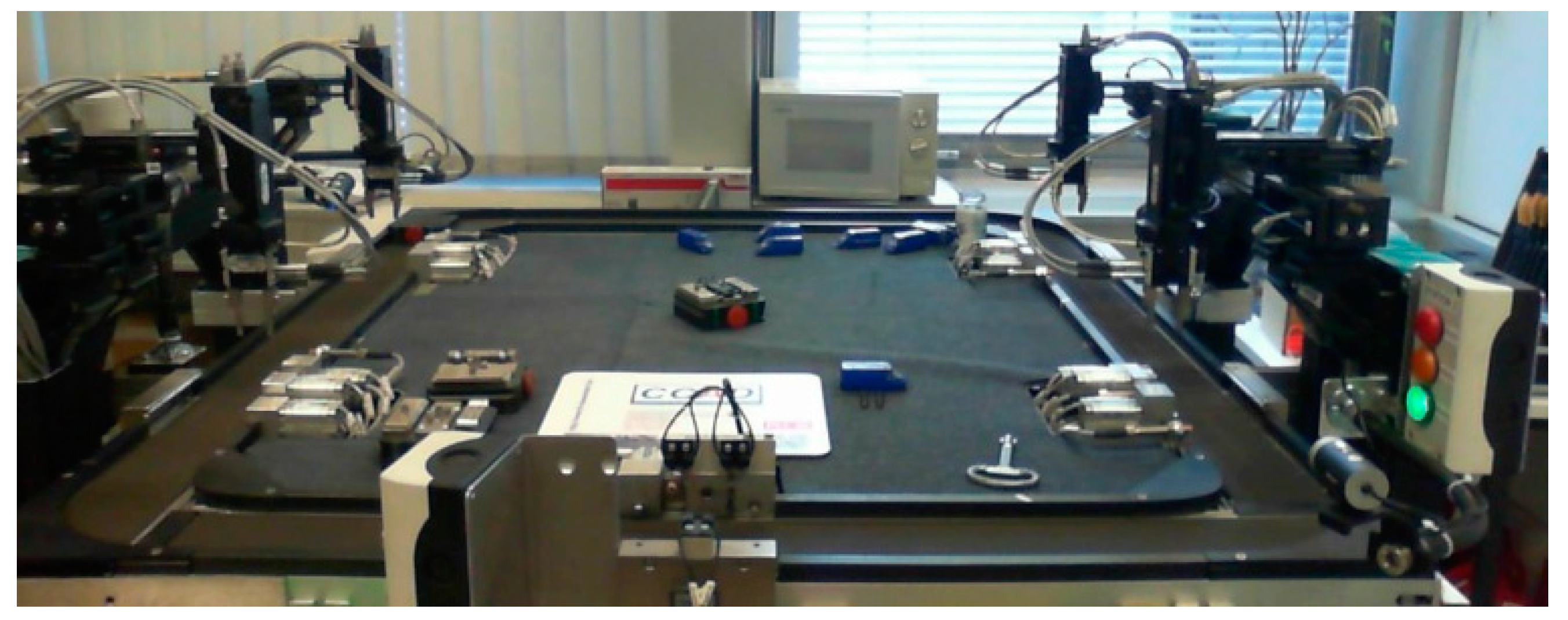
The application example 1 consists of a mounting system for model cars with five assembly/disassembly stations (Figure 15).
In standard mode, the system is operated with five classic PLC controllers (one PLC per station) from Siemens and Phoenix Contact. The average production time for a model car is 37 s.
For the SICS test, all five stations were connected to the Internet via device gateways/web connectors for OPC DA [16]. This means that all 135 process datums of the stations are available in the IP network. The SICS-SM control system for the station was designed in the web browser via the IoT Platform FlexIOT and by use of a special administration tool. A separate SICS controller instance is used for each of the five stations.
With the SICS-SM controller, the production time for a model car increases by approximately 10%. However, this allows the removal of five PLC controllers as hardware and their associated maintenance.
5.2. Application Example of a CICS-SMM Controller
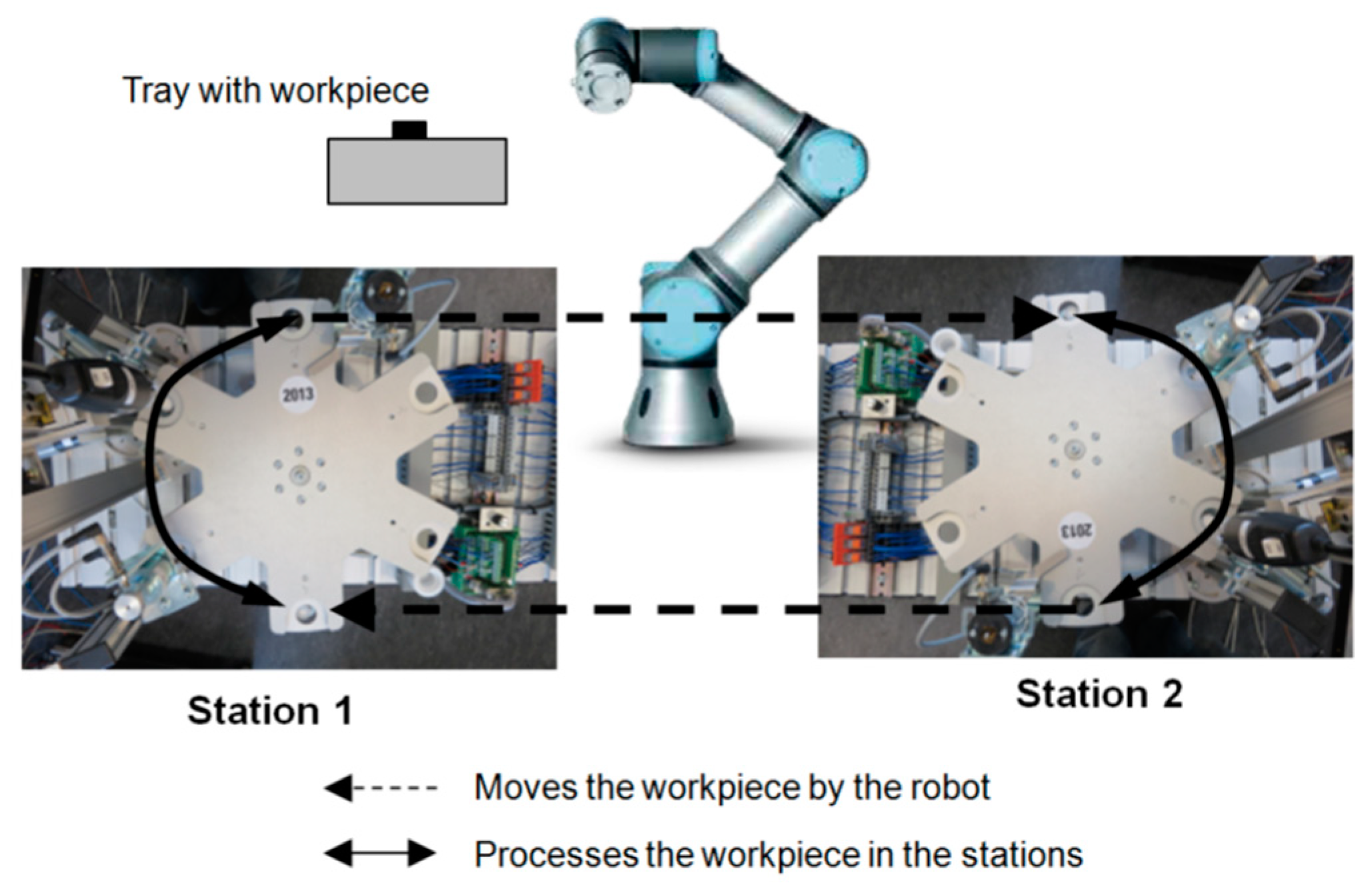
In application example 2, a SICS-SMM controller controls a working cell, consisting of two processing and test stations, and a loading robot. Figure 16 shows the technological structure for this example.
Two SICS controller instances control the two processing stations. Another SICS instance is responsible for coordinating the robot with the two stations. The connection of the respective SICS router instances to the devices of the two stations takes place via a universal gateway as a web connector [18]. The Modbus TCP interface of the robot is connected to the Internet via WebSocket using a device gateway, realized by means of Node-RED. The application was successfully presented at exhibition SPS/IPC/Drives 2016 in Nuernberg (Germany).
In contrast to example 1, the application example with the SICS SMM controller can be configured completely in the IoT platform. Additional administration tools are not required.
Using the clearing portal described above, the runtime of the control instances for the operation of the system can be fine-tuned analyzed and billed.
The possible realization of the further requirements, which are necessary for future industrial 4.0 solutions, was also demonstrated with the application examples.
- Orchestration of heterogeneous industrial control systems: Easy connection with robot control, proprietary I/O modules and servo drive from different manufacturers.
- Fast reconfiguration and agility (plug and work): The activation of completely new control programs and the I/O configuration is possible in a few seconds on the fly. Studies on synchronization and “safe state” issues are still pending.
- Remote control and improved manufacturer service: Remote control is an integral part. All data are already available in the cloud for diagnostic purposes without additional effort.
- Simulation support for planning and process optimization: Simulation and visualization models of the systems can be easily connected via the cloud.
- Application of smartphone and tablet PCs: Through browser technology and responsive design, all devices are ready to be used for operation.
5.3. Realtime Features
A SICS control system uses IP networks for data transmission, regardless of the solution variation. From the perspective of an automation technician, these networks are a priori neither reliable nor deterministic, and are not within the jurisdiction of the respective technical automation solution. Extensive time measurements for different communication structures were, therefore, performed for both SICS prototypes [19].
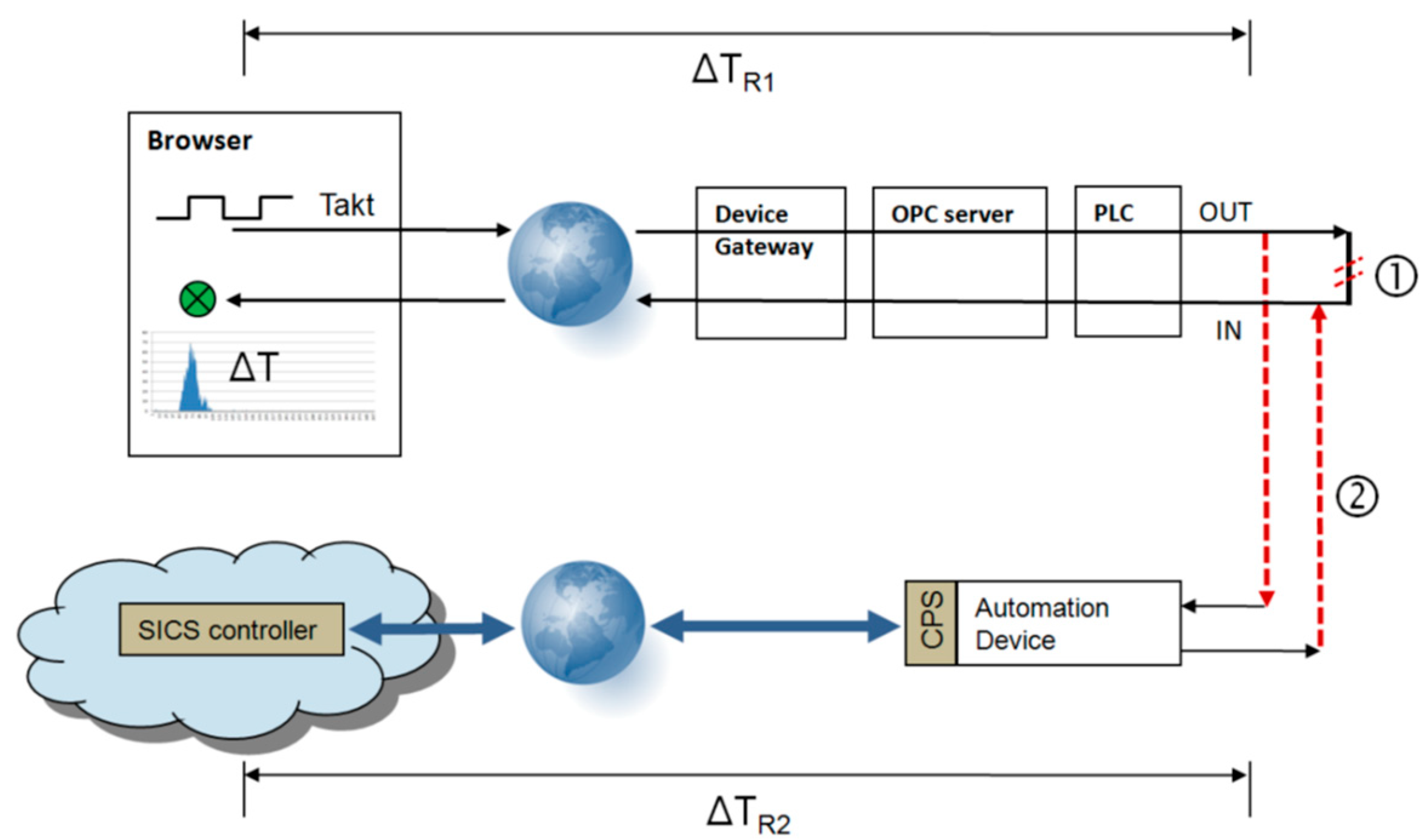
A practice-oriented method was chosen for the time measurements, which allows direct statements about the reaction time of the described SICS controllers. Figure 17 shows the measurement setup for the examples.
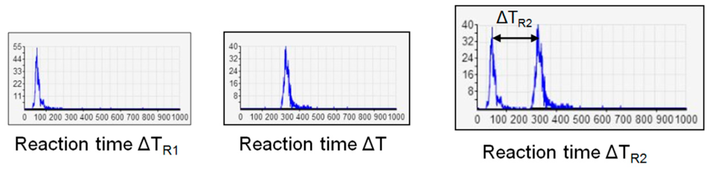
In the upper part of the measurement setup ➀, an HTML page generates a pulse frequency with a JavaScript generator, which is sent to a PLC a digital signal. This digital output is connected by a short circuit bridge to a PLC input, which sends its value back to the HTML page. A time difference measurement is then carried and recorded in a histogram. This gives the reaction time ΔTR1. Using this measurement method, the time characteristic of the process data transmission is obtained over a longer period of time and also detects the variance of the measurements over a probability curve.
In the second measuring part ➁, the short circuit bridge is opened at the PLC and the I/O signal is connected to an automation device (e.g., I/O module), which has a CPS interface and is controlled by a SICS controller. As a result, a histogram is displayed in the browser for the entire reaction time of the measurement setup
ΔT = ΔTR1 + ΔTR2.
The response time of the SICS controller thus results in
ΔTR2 = ΔT − ΔTR1.
Figure 18 shows the reaction time of the SICS controller.
With respect to the real-time features, the following general statement can thus be made:
With a SICS-SM or SICS-SMM solution, response times of about 80–100 ms at a 95% probability can be achieved by a usual Internet connection.
If the SICS controller is operated only on the Intranet, response times of under 40 ms can be achieved.
Altogether, the statement can be made that technical processes with process times of >150 ms (simple assembly processes, temperature and mixing processes, climate and energy processes, etc.) can already be performed successfully from the cloud by means of a SICS.
Compared to a classic PLC, it is currently not possible to guarantee 100% compliance with a specific time requirement for a SISC controller using IP networks and the cloud, but only with a certain probability. This must be taken into account in the respective application.
The majority of the response time is caused by the run times in the network. The actual cycle time for the execution of the control program in the SISC runtime is less than 1 ms. Considering the use of new real-time networks, e.g., time sensitive networking (TSN), is expected to allow SISC controllers in the local or edge computing networks to control drive motors as well.
5.4. Security and Safety
The reliability, data security and machine safety aspects were considered in a study of the operability of a SICS controller. An analysis and determination of the protective measures required for SICS was carried out. In addition, the required methods and measures for securing the process data access to networked sensors/actuators were investigated and tested using the example of encrypted access (HTTPS or WSS).
Critical aspects considered include: Disturbance of the process data communication, disconnection, runtime error in the SICS controller, connection delay and/or connection interruption, breaking into the cloud and modifying the files for SICS services and breaking into the client and/or into the cloud and disruption of the SICS operation.
In general, it can be estimated that there are deficits compared to a conventional PLC, especially with regards to machine safety, but these depend on the respective operating and application environment. However, the use of edge computing or the local connection of the sensors and actuators to a SISC controller can certainly provide workable solutions.
Interested readers are welcome to ask the authors about the topic further documents and research reports (in German).
5.5. Engineering
An important objective in SICS is the use of IEC 61131-3 programs which, as is usual in the classical PLC technology, are created with professional programming systems, such as CoDeSys (3S), PC WORX (Phoenix Contact) or STEP7/TIA Portal (Siemens). The basis for implementing of IEC 61131 programming with SISC is the representation of the control programs in the uniform format PLCopen XML. For the programming systems PC WORX, CoDeSys, STEP7 (TIA Portal) and openPCS, a special research study [20] analyzed the conformity with the PLCopen standard; and the capabilities of those tools to export and import PLC programs as PLCopen-compliant XML programs. The results of the study can be summarized as follows:
- Classic PLC programs exported as PLCopen XML programs by CoDeSys in the notation structured text (ST) or instruction list (IL) exported by PC WORX can form the basis for a SICS control program.
openPCS is not suitable as a programming environment for SICS because of instability during export of a PLCopen XML program. By means of STEP 7 (TIA-Portal), presently it is not possible to export a PLCopen XML according the standard IEC 61131-3.
The exported PLCopen XML programs in the IL or ST notation must be converted into the internal SICS-RT programming language (JavaScript) for executability in the SICS-RT. Two versions were developed and tested:
Version 1:
For a SICS-CM (Figure 6b), the IL program was executed after being translated (transformation of the PLCopen XML program into an internally suitable form) by loading the program into the SICS-RT using an interpreter. The interpreter was an inseparable part of the SICS-RT.
Version 2:
A separate ST compiler was developed for the SICS-SMM and SICS-SM, which compiles the PLCopen XML programs into directly executable JavaScript programs. The ST compiler was based on server-side JavaScript with node.js and functions as a web service for all SICS instances. The compiler is housed in a docker container and can be operated on any server.
Regardless of the programming language notation in the PLCopen XML program, however, there are some limitations to SICS engineering compared to the traditional setup of a PLC program, since the PLC engineering world does not have a common area within the Internet world (at least not right now). Among others, these include:
- Online debugging with PLC programming tools available on the market is not possible. Therefore, additional web-based testing possibilities (e.g., step operation and the output of step commands in the browser console) were introduced into the SICS controllers.
- Absolute addresses must be used for the I/O process data in the program. This can be easily implemented during the creation of the IEC 61131-3 control program
- The use of libraries or several tasks is up to now not possible. Thereto the compiler should be extended.
The lack of online debugging in the source code of the IEC 61131-3 program makes testing a SICS controller more difficult and increases the time required to develop an error-free SICS control program.
In summary, for SICS engineering, the engineering applied to industry, with a slightly higher cost compared to traditional PLC programming, is possible and can be used safely in a transitional period for the first SICS application solutions. In the long term, however, it is essential for smart control services to develop appropriate cloud and web-based engineering tools that fit seamlessly into the globally networked world of Industry 4.0 and the Industrial Internet of Things.
6. Conclusions
Using the concept of smart industrial control services, a new type of industrial control was developed and tested that allows for the complete detachment of control function and associated equipment to globally distributed, cloud-based software control services. A SICS controller is operated by a classic IEC61131-3 control program, thus ensuring the interoperability and industrial compatibility of the control system. The application of the service paradigm for industrial control functions significantly increases flexibility, meets industry 4.0 requirements such as changeability, reconfiguration and autonomy, and enables new business models to lease control functions.
Examples are presented that make clear the distinctions between general and methodological issues of a SICS.
For testing and evaluation, prototypical implementations were deployed for a purely server-based SICS controller and for a mixed client/server-based SICS controller. Both SICS controller types were successfully tested in the context of application scenarios from production automation. An evaluation of the SICS applications showed that simple technical processes with process times of greater than 150 ms can already be controlled reliably over the Internet.
With SICS, previous hardware-oriented and centralized procedures for the control of automated devices, machines and systems (e.g., PLC controllers) can be distributed and used transparently for uncritical real-time conditions (e.g., environmental processes, logistics processes, energy processes, simple assembly processes) through IP-network-distributed software functions.
Among other things, further research work in the project will focus on increased data security in the system through consistent encryption of communication for each SICS component; reduction of the latencies for process data communication between the SICS controller; the automation devices through optimized web protocols; the use of TSN as a deterministic IP network; examination of the practicability (long-term testing) of a SICS control system for climate control and lighting control of an office building in everyday life; investigating the application of block chain and distributed ledger technologies for the identification management in a SISC control system; and last but not least, testing the business model for the leasing of control functions by an IoT platform with integrated smart SICS services.
Author Contributions
R.L. authored the main text and M.S. added some parts (e.g., testing a SICS-SMM controller), gave recommendations and suggestions and re-edited the text.
Funding
A part of this research work was funded by Federal Ministry for Economic Affairs and Energy, grant number IGF 18354N.
Conflicts of Interest
The authors declare no conflict of interest.
References
- Kagermann, H.; Wahlster, W.; Helbig, J. Recommendations for Implementing the Strategic Initiative INDUSTRIE 4.0; Research union: Business-Science; National Academy of Science and Engineering: Munich, Germany, April 2013. [Google Scholar]
- WAGO Kontakttechnik GmbH: Effective Upgrade: A Plug-In Makes WAGO Controllers IoT-Ready. Available online: https:/www.wago.com/us/plc-mqtt-iot (accessed on 23 April 2019).
- EU Project: SOCRADES. 2006–2009. Available online: http://www.socrades.net (accessed on 10 September 2019).
- Colombo, A.W.; Bangemann, T.; Karnouskos, S.; Delsing, J.; Stluka, P.; Harrison, R.; Jammes, F.; Lastra, J.L. Industrial Cloud-Based Cyber-Physical Systems; Springer International Publishing: Zug, Swiss, 2014. [Google Scholar]
- Microsoft: Introducing DPWS. 2015. Available online: https://msdn.microsoft.com/en-us/library/dd170125.aspx (accessed on 23 June 2018).
- ISW of the University Stuttgart: Industrial Cloud-Based Control Platform for the Production with Cyber-Physical Systems (piCASSO-in German)—BMBF-Verbundprojekt, Stuttgart. 2013. Available online: http://www.projekt-picasso.de/index (accessed on 10 September 2019).
- Grischan, E.; Stahl, C.; Greiner, T.; Barth, M.; Gorecky, D. Cloud-Based Automation. atp ed. 2015, 3, 38–47. (In German) [Google Scholar]
- Schmitt, J.; Goldschmidt, T.; Vorst, P. Cloud-Enabled Automation Systems Using OPC UA. atp ed. 2014, 7, 34–40. [Google Scholar] [CrossRef]
- Cristani, M.; Demrozi, F.; Tomazzoli, C. ONTO-PLC: An ontology-driven methodology for converting PLC industrial plants to IoT. Proced. Comput. Sci. 2018, 126, 527–536. [Google Scholar] [CrossRef]
- Langmann, R.; Stiller, M. Control Services from the Cloud According IEC 61131. atp ed. 2017, 4, 3–15. (In German) [Google Scholar]
- Langmann, R.; Meyer, L. Architecture of a Web-oriented Automation System. In Proceedings of the 18th IEEE International. Conference on Emerging Technologies & Factory Automation (ETFA 2013), Cagliari, Italy, 10–13 September 2013. [Google Scholar]
- Competence Center Automation Düsseldorf (CCAD): Description of a Virtual Device; R&D Document; CCAD: Düsseldorf, Germany, 2013. (In German)
- Brass, M. Development and Analysis of a Web and Cloud-Based Runtime Environment for Dynamic Control of Automated Station. Master’s Thesis, Hochschule Duesseldorf University of Applied Sciences, Düsseldorf, Germany, 2016. (In German). [Google Scholar]
- Coppenrath, M. Development, Test and Evaluation of a Server-Based Control Service by Node.js. Master’s Thesis, Hochschule Duesseldorf University of Applied Sciences, Düsseldorf, Germany, 2018. (In German). [Google Scholar]
- Aschbacher, H: Smart Services—Fachhochschule CAMPUS 02. Available online: http://www.serviceengineering.at/blog/?page_id=274 (accessed on 23 April 2019).
- Langmann, R. Automation Systems with Web Technology. atp ed. 2014, 10, 887–897. (In German) [Google Scholar]
- Zechel, C. Developing of a Clearing System for Determination, Storing and Analysis of Using Times of Automation Services in an Industry 4.0 Environment. Master’s Thesis, Hochschule Duesseldorf University of Applied Sciences, Düsseldorf, Germany, 2017. (In German). [Google Scholar]
- Langmann, R. HTML5-Based Web Connector for OPC (in German); A&D-Kompendium 2014/2015; Publish Industry Verlag: Munich, Germany, 2014; pp. 54–56. [Google Scholar]
- Braß, M. Development and Test of an Industry 4.0 Gateway for the Internet Access to Modbus TCP and Proprietary TCP Protocols; Documentation of Project Work; Hochschule Duesseldorf University of Applied Sciences: Düsseldorf, Germany, 25 January 2016. (In German) [Google Scholar]
- Rojas-Peña, L. IEC 61131-3 Programming in CICS-Problems and Possible Solutions; Study Report; Hochschule Duesseldorf University of Applied Sciences: Düsseldorf, Germany, 7 October 2015. [Google Scholar]
Figure 1.
Structure of a PLC as a cyber physical systems (CPS) component.

Figure 2.
Evolution of a PLC as a CPS component Industrial Control. (a) PLC with program components CPb and CPc (b) PLC only with CPc component (c) The PLC hardware contains only sensors and actuators
Figure 2.
Evolution of a PLC as a CPS component Industrial Control. (a) PLC with program components CPb and CPc (b) PLC only with CPc component (c) The PLC hardware contains only sensors and actuators

Figure 3.
C33 controller.

Figure 4.
General structure of a smart industrial control service (SICS) controller.

Figure 5.
Component structure and communication paths for server-based SICS solutions. (a) Server mode (SM); (b) server-based mixed mode (SMM).
Figure 5.
Component structure and communication paths for server-based SICS solutions. (a) Server mode (SM); (b) server-based mixed mode (SMM).

Figure 6.
Component structure and communication paths for client-based SICS solutions. (a) Client-based mixed mode (CMM); (b) client mode (CM).
Figure 6.
Component structure and communication paths for client-based SICS solutions. (a) Client-based mixed mode (CMM); (b) client mode (CM).

Figure 7.
SICS services architecture according Figure 4 presented as an entity relationship diagram (ERD) diagram.
Figure 7.
SICS services architecture according Figure 4 presented as an entity relationship diagram (ERD) diagram.

Figure 8.
SICS router.

Figure 9.
SICS controller in the server-based mixed mode (SMM).

Figure 10.
Implementation structure of a SICS SMM controller at runtime (s—server-based part; c—client-based part).
Figure 10.
Implementation structure of a SICS SMM controller at runtime (s—server-based part; c—client-based part).

Figure 11.
SICS controller in the server-based mode (SM).

Figure 12.
Implementation structure of a SICS SM controller at runtime (s—server-based part; c—client-based part).
Figure 12.
Implementation structure of a SICS SM controller at runtime (s—server-based part; c—client-based part).

Figure 13.
Basic structure of the interaction between the FlexIOT portal and the clearing system.

Figure 14.
Settlement and analysis in the clearing system for an example with five SISC-SMM controller instances.
Figure 14.
Settlement and analysis in the clearing system for an example with five SISC-SMM controller instances.

Figure 15.
Mounting system for model cars with five assembly/disassembly stations.

Figure 16.
Technological structure of application example 2.

Figure 17.
Measurement setup to determine the reaction time of a SICS controller.

Figure 18.
Determination of the reaction time of a SICS controller.


Table 1.
Industry 4.0 (I40) Capability of a PLC controller.
| Class | Service Ability (SA) | Control Locality (CL) |
|---|---|---|
| 0 | No service | All control programs are encapsulated locally in the PLC hardware. |
| 1 | Services only for non-critical and overarching functionalities | Some control programs that include non-critical and overarching functionalities are not located on the local hardware but are instead distributed to other systems (for example, in the network). |
| 2 | Services for most functions available | Most control programs are distributed in the network. Control programs which are critical in terms of time and safety remain in the local PLC hardware. |
| 3 | All control functions as services. | All control programs are distributed in the network. Third instances can access all the control algorithms in real time. |
Table 2.
Operating modes of a SICS runtime.
| Mode | Description |
|---|---|
| EXISTENT | The SICS-RT service is instantiated and is available for operation. |
| READY | The PLCopen XML program, whose URL is specified in the SICS-RT instance, is loaded. Depending on the type of execution of the control program (interpretative or as a compiled program), the XML program is loaded, translated or compiled in this state and stored in an internal format suitable for runtime operation. |
| AUTOMATIC | In the AUTOMATIC state, the control program is processed and the internal I/O image of the control is updated. |
| STEP | The STEP status allows step-by-step processing of the PLC program for debugging purposes. Each current step is displayed in the user interface of the SICS-RT instance (HMI proxy) and/or in the web console of the browser. |
| SUSPEND | The SICS-RT is stopped and all outputs are set to FALSE/0. The loaded control program is deleted. The status is automatically exited after approximately 2 s. |
© 2019 by the authors. Licensee MDPI, Basel, Switzerland. This article is an open access article distributed under the terms and conditions of the Creative Commons Attribution (CC BY) license (http://creativecommons.org/licenses/by/4.0/).
Share and Cite
MDPI and ACS Style
Langmann, R.; Stiller, M. The PLC as a Smart Service in Industry 4.0 Production Systems. Appl. Sci. 2019, 9, 3815. https://doi.org/10.3390/app9183815
AMA Style
Langmann R, Stiller M. The PLC as a Smart Service in Industry 4.0 Production Systems. Applied Sciences. 2019; 9(18):3815. https://doi.org/10.3390/app9183815
Chicago/Turabian StyleLangmann, Reinhard, and Michael Stiller. 2019. "The PLC as a Smart Service in Industry 4.0 Production Systems" Applied Sciences 9, no. 18: 3815. https://doi.org/10.3390/app9183815
Note that from the first issue of 2016, this journal uses article numbers instead of page numbers. See further details here.