A Reflective Augmented Reality Integral Imaging 3D Display by Using a Mirror-Based Pinhole Array

1
School of Electronics and Information Engineering, Sichuan University, Chengdu 610065, China
2
School of Instrumentation and Optoelectronic Engineering, Beihang University, Beijing 100191, China
*
Author to whom correspondence should be addressed.
Appl. Sci. 2019, 9(15), 3124; https://doi.org/10.3390/app9153124
Submission received: 30 June 2019
/
Revised: 28 July 2019
/
Accepted: 30 July 2019
/
Published: 1 August 2019
(This article belongs to the Special Issue Augmented Reality: Current Trends, Challenges and Prospects)
Abstract
:In this paper, we propose a reflective augmented reality (AR) display system based on integral imaging (II) using a mirror-based pinhole array (MBPA). The MBPA, obtained by punching pinholes on a mirror, functions as a three-dimensional (3D) imaging device, as well as an image combiner. The pinhole array of MBPA can realize a pinhole array-based II display, while the mirror of MBPA can image the real objects, so as to combine the images of the real objects with the reconstructed 3D images. The structure of the proposed reflective AR display is very simple, and only a projection system or a two-dimensional display screen is needed to combine with the MBPA. In our experiment, a 25cm × 14cm sized AR display was built up, a combination of a 3D virtual image and a real 3D object was presented by the proposed AR 3D display. The proposed device could realize an AR display of large size due to its compact form factor and low weight.
1. Introduction
With the development of display technologies, electronic display devices have to meet people’s higher requirements. Augmented reality (AR) displays, which allow the overlaying of digital information onto a direct view of the real world so that the two-dimensional (2D) or three-dimensional (3D) images are seamlessly combined with the real-world scene, have been widely of interest to researchers and the industry [1,2,3,4]. There has been great desire for AR in many applications, such as medical visualization, surgical training, flight simulation, and entertainment [5,6,7,8]. Basically, there are two types of AR displays, which are optical see-through AR displays and video see-through AR displays [9,10,11,12,13]. Optical see-through AR displays, compared to video see-through AR displays [14,15], can provide a non-obstructed visualization of the real environment that guarantees that the visual and proprioception information will be synchronized and maintains see-through vision to the real world, and therefore has attracted much research interest. Additionally, integral imaging (II), a 3D imaging technique which provides auto-stereoscopic images without the help of special glasses [16,17,18], is very suitable for displaying 3D images in the optical see-through AR display system. Moreover, the structure of II is very compact, which makes it suitable for the AR system to display 3D images.
Some works have been proposed to achieve AR display with 3D images, a method of using free-form optics to magnify the 3D images reconstructed by a micro-II display unit and to overlap the 3D images with the real world, was reported by Hua [19]; another useful way to transfer 3D images into the viewer’s eyes through total internal reflection in an optical waveguide was also proposed, and achieved a good transmittance of the real-world lights [20]. Researchers have also proposed to realize an AR display by folding virtual 3D images into space with a semi-transparent mirror [21]. However, AR systems using these methods are more suitable for near-eye displays because of the size limitation, known as one of the common shortcomings, of the display screen or view box. To achieve a more compact structure for an AR system, the use of a lens array holographic optical element (HOE) has been proposed [22,23], but the size of the lens array HOE only reached several centimeters [24,25].
In this paper we propose, for the first time, a reflective AR system using a mirror-based pinhole array (MBPA). The real-world scene is reflected by the mirror area of the MBPA, and the 3D images are reconstructed by a pinhole array-based II unit. Due to its compact form factor, the proposed AR display system has the advantages of lower cost, no distortions, and more importantly, ease of manufacturing large-sized display screens.
2. Principle
2.1. Pinhole Array Based II Display
Figure 1 shows the schematic diagram of a pinhole array-based II technology including two parts: the pickup process and the display process [26]. In the pickup process, the light emitted from the 3D object is transmitted through pinholes in the pinhole array, and the lights go through each pinhole form an elemental image (EI) on the imaging sensor. The set of EIs recorded on the imaging sensor form an elemental image array (EIA), which contains different perspectives on the 3D object. In the display process, the captured EIA is displayed on a 2D display screen. The pinhole array is located in front of the 2D display screen to modulate the lights from the EIA. As shown by the blue dots in Figure 1b, lights emitted from the homologous pixels of a 3D object point intersect in the space to form a 3D voxel in front of the pinhole array. All of the 3D voxels constitute the 3D image.
2.2. Proposed Reflective AR Display
The schematic diagram of the proposed reflective AR display system using an MBPA is shown in Figure 2. Figure 2a shows the structure of the MBPA, which contains the pinholes and mirror area. The pinholes on the MBPA are white circular, while the other parts of the MBPA represent the mirror area. The MBPA can be obtained by punching pinholes with uniform horizontal and vertical spacing on a mirror. The pinholes on MBPA can transmit lights and form a 3D image like the traditional pinhole array-based II display does, as shown in Figure 2b. The mirror area of the MBPA can reflect the lights from the real scene, and a mirror image of the real scene is imaged on the opposite side of the MBPA, shown in Figure 2c. As a result, the viewers in front of the display device can receive the transmitted lights (the 3D image) and the reflected lights (the mirror image), simultaneously. In this way the combined AR contents are obtained. The MBPA functions as a 3D imaging device as well as an image combiner.
3. Experiments and Results
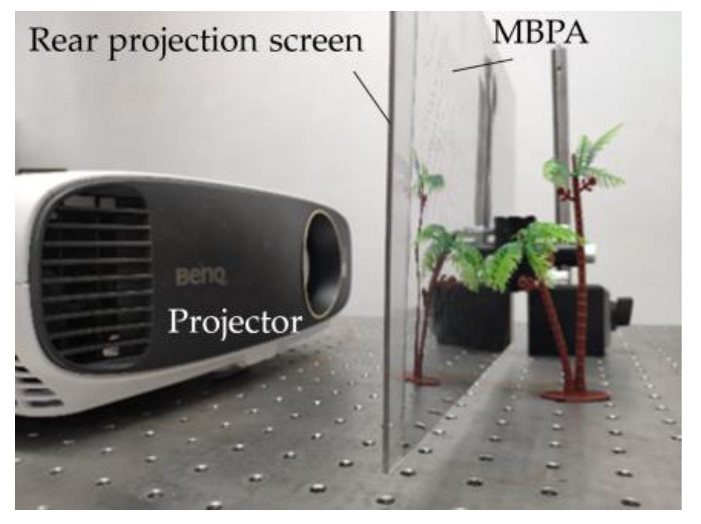
To verify the feasibility of the proposed reflective AR display system, an experimental system was built, as shown in Figure 3. The experimental system consists of a projector, a rear projection screen and a MBPA. The projector with high brightness was used to displace the 2D display screen in order to improve the brightness of the 3D images. According to the projection ratio of the projector we used, the size of the AR display was determined to be 25 cm × 14 cm. A 25 cm × 14 cm sized reflective film on which the pinholes were engraved by a laser engraving machine was attached on a transparent acrylic plate to implement the MBPA. The pinholes on the MBPA can transmit the light from the EIA, while the other parts of the MBPA can reflect the light from the real object. The rear projection screen was attached to the other side of the acrylic plate substrate to receive EIA projected by the high luminance projector. From our previous research work [27], the viewing angle was calculated, and the spatial angular resolution referred to the viewpoints number per degree was 0.575. The parameters of the reflective AR display system developed are shown in Table 1.
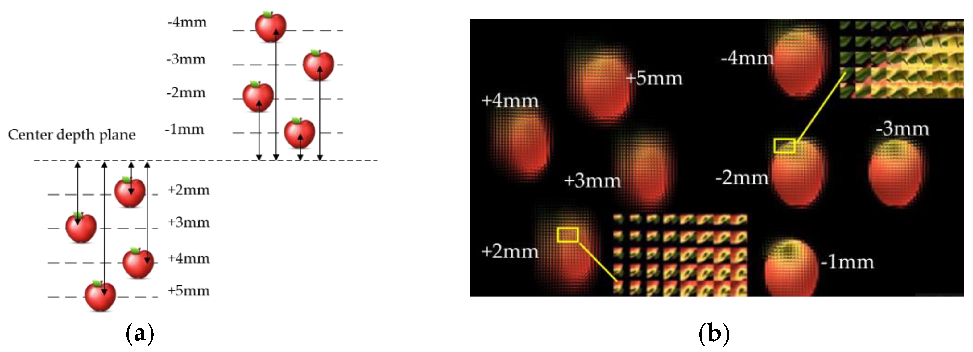
As shown in Figure 4a, a 3D scene consisting of eight apples was built up at different depths in 3d Max software, and their depths were −4 mm, −3 mm, −2 mm, −1 mm, 2 mm, 3 mm, 4 mm, and 5 mm, respectively. An EIA was generated by using the sparse camera array method [28]. As shown in Figure 4b, the EIA contained 167 × 94 elemental images, and each elemental image had 23 × 23 pixels. A portion of the EIA in Figure 4b has been enlarged, from which we can see several perspectives on the apple. A 4K projector was used to project the EIA onto the rear projection screen, and the re-projection transformation algorithm was used to align the projected EIA and the pinhole array on the MBPA. A coconut palm tree, which represents the real object, was located in front of the MBPA.
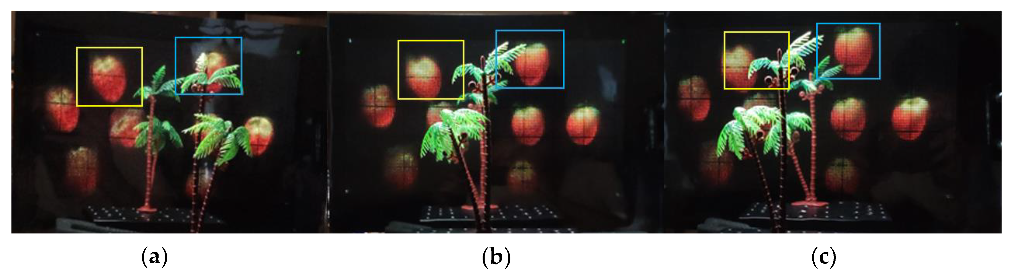
Figure 5 shows the different AR views of the reconstructed 3D images and the mirror image. The reference rectangles were drawn in Figure 5 to illustrate that the relative positions of the eight apples and the coconut palm tree changed when the viewpoints moved from left to right. The left four apples and the viewpoints move in the opposite direction, while the right four apples move in the same direction with the viewpoint. This proves that the reconstructed 3D images of the left four apples were located in front of the MBPA, and 3D images of the right four apples were located behind of the MBPA. The apples with large depths moved faster than those with small depths. The experimental results showed that the proposed system can realize a good AR display effect by combining the reconstructed 3D image and the mirror image with the MBPA.
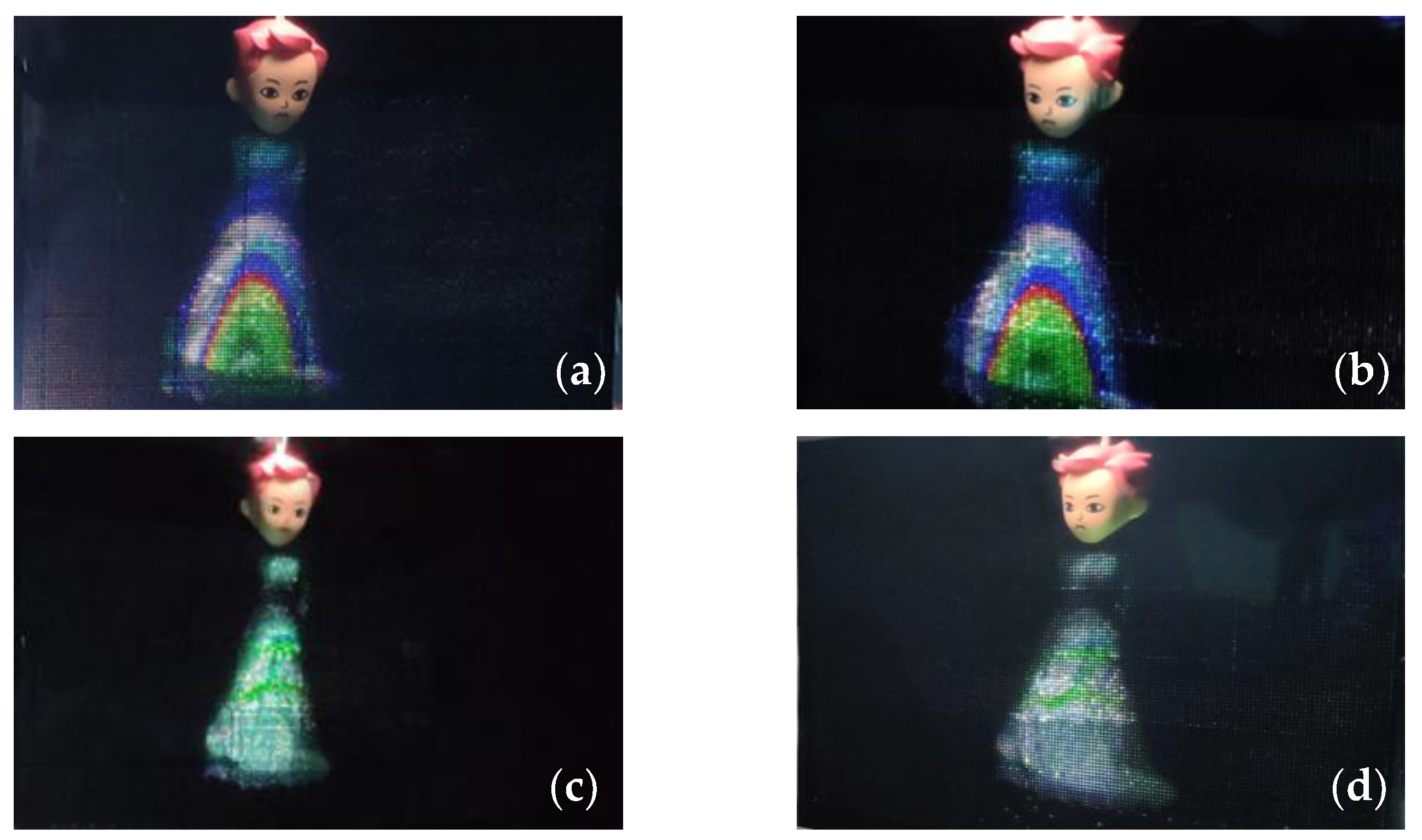
The proposed AR display can be used in AR shopping. As shown in Figure 6, we designed an application scenario for AR fitting. A doll stood in front of the reflective AR display system, and a 3D image of a dress was displayed on her mirror image, as if she was wearing the dress. The experimental results confirm that the proposed AR display can be used for AR fitting. Just by changing the EIA, the virtual 3D dress can be changed very fast. A great deal of time will be saved when selecting clothes at mall or at home.
4. Discussions
The resolution of the system is determined by the number of pinholes, because the viewer sees one pixel from each EI, and the brightness of the system is directly affected by the pinhole size. The 3D resolution of the pinhole array-based II 3D display can be improved by increasing the number of pinholes. With the increase in the number of pinholes, however, the number of EIs increases accordingly (since each a pinhole corresponds to an EI). As a result, a 2D display screen with ultra-high resolution is needed. So the 4K high-resolution projector was used in our experiments. In addition, some research groups have also improved the resolution of pinhole array-based IIs by using time-division or space-division multiplexing technologies [29,30].The brightness of the system is affected by the pinhole size. When the pinhole size increases, the brightness and contrast of the system both increase. However, a large pinhole size will cause more pixels to be observed at a given viewing point through each pinhole (which results in crosstalk image). To compensate for the loss of brightness, a high-brightness projector was used in our experiment. The brightness of the projector was several times that of a 2D display screen.
5. Conclusions
In conclusion, in this paper we have proposed a reflective AR display using an MBPA. The MBPA functions using 3D imaging and mirror imaging. The 3D image was reconstructed through the pinhole array of the MBPA, and the real object was reflected by the mirror area of the MBPA, so as to achieve the effect of AR display by allowing viewers to receive the 3D image and the virtual image of a real object simultaneously. The proposed AR display system is simple in its structure and is easy to realize as a large-size display. It could be widely applied in business, such as AR shopping and more. However, one of the remaining problems is the low brightness of the reconstructed 3D image; it is possible, as we expected, to improve on this by properly enlarging the size of pinholes, or attaching another reflective film on the reverse side of the MBPA to recycle the light emitted from the display screen.
Author Contributions
Q.L. and H.D. conceived the original idea and wrote the paper; S.P., W.J. and Q.W. conducted experiments assistance.
Funding
This research was funded by the National Key R&D Program of China, grant number 2017YFB1002900, the National Natural Science Foundation of China, grant number 61775151 and the Innovative Spark Project of Sichuan University, grant number 2018SCUH0003.
Conflicts of Interest
The authors declare no conflict of interest.
References
- Azuma, R.; Baillot, Y.; Behringer, R.; Feiner, S.; Julier, S.; MacIntyre, B. Recent advances in augmented reality. IEEE Comput. Graph. Appl. 2001, 21, 34–47. [Google Scholar] [CrossRef]
- Azuma, R.T. A survey of augmented reality. Presence Teleoper. Virtual Environ. 1997, 6, 355–385. [Google Scholar] [CrossRef]
- Van Krevelen, R. Augmented Reality: Technologies, Applications, and Limitations. 2007. Available online: https://www.researchgate.net/publication/292150312_Augmented_Reality_Technologies_Applications_and_Limitations (accessed on 30 June 2019).
- Zhou, F.; Duh, H.B.L.; Billinghurst, M. Trends in Augmented Reality Tracking, Interaction and Display: A Review of Ten Years of ISMAR. In Proceedings of the 7th IEEE/ACM International Symposium on Mixed and Augmented Reality, Cambridge, UK, 15–18 September 2008; pp. 193–202. [Google Scholar]
- Carmigniani, J.; Furht, B.; Anisetti, M.; Ceravolo, P.; Damiani, E.; Ivkovic, M. Augmented reality technologies, systems and applications. Multimed. Tools Appl. 2011, 51, 341–377. [Google Scholar] [CrossRef]
- Kang, X.; Azizian, M.; Wilson, E.; Wu, K.; Martin, A.D.; Kane, T.D.; Peters, C.A.; Cleary, K.; Shekhar, R. Stereoscopic augmented reality for laparoscopic surgery. Surg. Endosc. 2014, 28, 2227–2235. [Google Scholar] [CrossRef] [PubMed]
- Li, L. Application of Augmented Reality Technology in Piano Teaching System Design. Educ. Sci. Theory Pract. 2018, 18, 1712–1721. [Google Scholar] [CrossRef]
- Wang, J.C.; Suenaga, H.; Liao, H.G.; Hoshi, K.; Yang, L.J.; Kobayashi, E.; Sakuma, I. Real-time computer-generated integral imaging and 3D image calibration for augmented reality surgical navigation. Comput. Med. Imaging Graph. 2015, 40, 147–159. [Google Scholar] [CrossRef] [PubMed]
- Cutolo, F.; Fontana, U.; Carbone, M.; D’Amato, R.; Ferrari, V. Hybrid Video/Optical See-Through HMD. In Proceedings of the 2017 IEEE International Symposium on Mixed and Augmented Reality (Ismar-Adjunct), Nantes, France, 9–13 October 2017; Volume 31, pp. 52–57. [Google Scholar]
- Genc, Y.; Sauer, F.; Wenzel, F.; Tuceryan, M.; Navab, N. Optical see-through HMD calibration: A stereo method validated with a video see-through system. In Proceedings of the IEEE and ACM International Symposium on Augmented Reality, Munich, Germany, 5–6 October 2000; pp. 165–174. [Google Scholar]
- Hua, H.; Javidi, B. A 3D integral imaging optical see-through head-mounted display. Opt. Express 2014, 22, 13484–13491. [Google Scholar] [CrossRef] [PubMed]
- Liu, S.; Li, Y.; Zhou, P.; Chen, Q.; Su, Y. Reverse-mode PSLC multi-plane optical see-through display for AR applications. Opt. Express 2018, 26, 3394–3403. [Google Scholar] [CrossRef]
- Shen, X.; Javidi, B. Large depth of focus dynamic micro integral imaging for optical see-through augmented reality display using a focus-tunable lens. Appl. Optics. 2018, 57, B184–B189. [Google Scholar] [CrossRef]
- Caruso, G.; Cugini, U. Augmented Reality Video See-through HMD Oriented to Product Design Assessment. In Proceedings of the International Conference on Virtual and Mixed Reality, Las Vegas, FL, USA, 15–20 July 2009; Volume 5622, pp. 532–541. [Google Scholar]
- Cutolo, F.; Ferrari, V. The Role of Camera Convergence in Stereoscopic Video See-through Augmented Reality Displays. Int. J. Adv. Comput. Sci. Appl. 2018, 9, 12–17. [Google Scholar] [CrossRef]
- Jung-Young, S.; Shin-Hwan, K.; Dae-Sik, K.; Javidi, B.; Kae-Dal, K. Image-Forming Principle of Integral Photography. J. Disp. Technol. 2008, 4, 324–331. [Google Scholar] [CrossRef]
- Lippmann, G. Reversible test prints. Integral photographies. Cr. Hebd. Acad. Sci. 1908, 146, 446–451. [Google Scholar]
- Xiao, X.; Javidi, B.; Martinez-Corral, M.; Stern, A. Advances in three-dimensional integral imaging: Sensing, display, and applications. Appl. Opt. 2013, 52, 546–560. [Google Scholar] [CrossRef] [PubMed]
- Cheng, D.; Wang, Y.; Hua, H.; Sasian, J. Design of a wide-angle, lightweight head-mounted display using free-form optics tiling. Opt. Lett. 2011, 36, 2098–2100. [Google Scholar] [CrossRef]
- Kim, S.-B.; Park, J.-H. Optical see-through Maxwellian near-to-eye display with an enlarged eyebox. Opt. Lett. 2018, 43, 767–770. [Google Scholar] [CrossRef] [PubMed]
- Hong, J.; Min, S.-W.; Lee, B. Integral floating display systems for augmented reality. Appl. Opt. 2012, 51, 4201–4209. [Google Scholar] [CrossRef] [PubMed]
- He, M.Y.; Zhang, H.L.; Deng, H.; Li, X.W.; Li, D.H.; Wang, Q.H. Dual-view-zone tabletop 3D display system based on integral imaging. Appl. Opt. 2018, 57, 952–958. [Google Scholar] [CrossRef] [PubMed]
- Zhang, H.L.; Deng, H.; Yu, W.T.; He, M.Y.; Li, D.H.; Wang, Q.H. Tabletop augmented reality 3D display system based on integral imaging. J. Opt. Soc. Am. B 2017, 34, B16–B21. [Google Scholar] [CrossRef]
- Jang, C.; Hong, K.; Yeom, J.; Lee, B. See-through integral imaging display using a resolution and fill factor-enhanced lens-array holographic optical element. Opt. Express 2014, 22, 27958–27967. [Google Scholar] [CrossRef]
- Deng, H.; Chen, C.; He, M.-Y.; Li, J.-J.; Zhang, H.-L.; Wang, Q.-H. High-resolution augmented reality 3D display with use of a lenticular lens array holographic optical element. J. Opt. Soc. Am. A 2019, 36, 588–593. [Google Scholar] [CrossRef] [PubMed]
- Deng, H.; Wang, Q.-H.; Wu, F.; Luo, C.-G.; Liu, Y. Cross-talk-free integral imaging three-dimensional display based on a pyramid pinhole array. Photonics Res. 2015, 3, 173–176. [Google Scholar] [CrossRef]
- Deng, H.; Wang, Q.H.; Li, L.; Li, D.H. An integral-imaging three-dimensional display with wide viewing angle. J. Soc. Inf. Disp. 2011, 19, 679–684. [Google Scholar] [CrossRef]
- Deng, H.; Wang, Q.; Li, D. Method of generating orthoscopic elemental image array from sparse camera array. Chin. Opt. Lett. 2012, 10, 061102. [Google Scholar] [CrossRef]
- Schwarz, A.; Wang, J.G.; Shemer, A.; Zalevsky, Z.; Javidi, B. Lensless three-dimensional integral imaging using variable and time multiplexed pinhole array. Opt. Lett. 2015, 40, 1814–1817. [Google Scholar] [CrossRef] [PubMed]
- Jang, J.S.; Oh, Y.S. Spatiotemporally multiplexed integral imaging projector for large-scale high-resolution three-dimensional display. Opt. Express 2004, 12, 557–563. [Google Scholar] [CrossRef] [PubMed]
Figure 1.
(a) Pickup process and (b) display process of the pinhole array-based II.

Figure 2.
(a) The structure of the mirror-based pinhole array (MBPA), it consists of two parts: pinholes and mirror; (b) the 3D image formed by the lights of an elemental image array (EIA) transmitted through the pinholes of MBPA; (c) the mirror image formed by the reflected light of the real object reflected by the mirror area of the MBPA; and (d) the augmented reality (AR) display of the proposed reflective AR 3D display.

Figure 3.
The experimental system of the proposed reflective AR display.

Figure 4.
(a) Eight apples in 3d Max software; (b) generated EIA.

Figure 5.
Different views of the 3D image reconstructed by the proposed prototype. (a) Left view, (b) center view, and (c) right view.
Figure 5.
Different views of the 3D image reconstructed by the proposed prototype. (a) Left view, (b) center view, and (c) right view.

Figure 6.
AR fitting application by using the proposed prototype. (a) Right view; (b) left view; (c) right view, and (d) left view.
Figure 6.
AR fitting application by using the proposed prototype. (a) Right view; (b) left view; (c) right view, and (d) left view.


Table 1.
Specifications of the AR display system developed.
| Components | Specifications | Values |
|---|---|---|
| Projector | Resolution Product model luminance | 3840 pixels × 2160 pixels BenQ HD2934 2000-2999 lm |
| EIA | Resolution Size Pixel pitch Resolution of each EI | 3840 pixels × 2160 pixels 250 mm × 140 mm 65.1 µm 23 pixels × 23 pixels |
| MBPA | Pinhole size Pinhole pitch Numbers of pinholes Thickness of MBPA viewing angle Spatial angle resolution | 0.25 mm 1.5 mm 167 × 94 0.2 mm 41.1° 0.575 |
© 2019 by the authors. Licensee MDPI, Basel, Switzerland. This article is an open access article distributed under the terms and conditions of the Creative Commons Attribution (CC BY) license (http://creativecommons.org/licenses/by/4.0/).
Share and Cite
MDPI and ACS Style
Li, Q.; Deng, H.; Pang, S.; Jiang, W.; Wang, Q. A Reflective Augmented Reality Integral Imaging 3D Display by Using a Mirror-Based Pinhole Array. Appl. Sci. 2019, 9, 3124. https://doi.org/10.3390/app9153124
AMA Style
Li Q, Deng H, Pang S, Jiang W, Wang Q. A Reflective Augmented Reality Integral Imaging 3D Display by Using a Mirror-Based Pinhole Array. Applied Sciences. 2019; 9(15):3124. https://doi.org/10.3390/app9153124
Chicago/Turabian StyleLi, Qiang, Huan Deng, Senlin Pang, Wenhao Jiang, and Qionghua Wang. 2019. "A Reflective Augmented Reality Integral Imaging 3D Display by Using a Mirror-Based Pinhole Array" Applied Sciences 9, no. 15: 3124. https://doi.org/10.3390/app9153124
Note that from the first issue of 2016, this journal uses article numbers instead of page numbers. See further details here.