Holographic Three-Dimensional Virtual Reality and Augmented Reality Display Based on 4K-Spatial Light Modulators

 ,
, 
Abstract
:1. Introduction
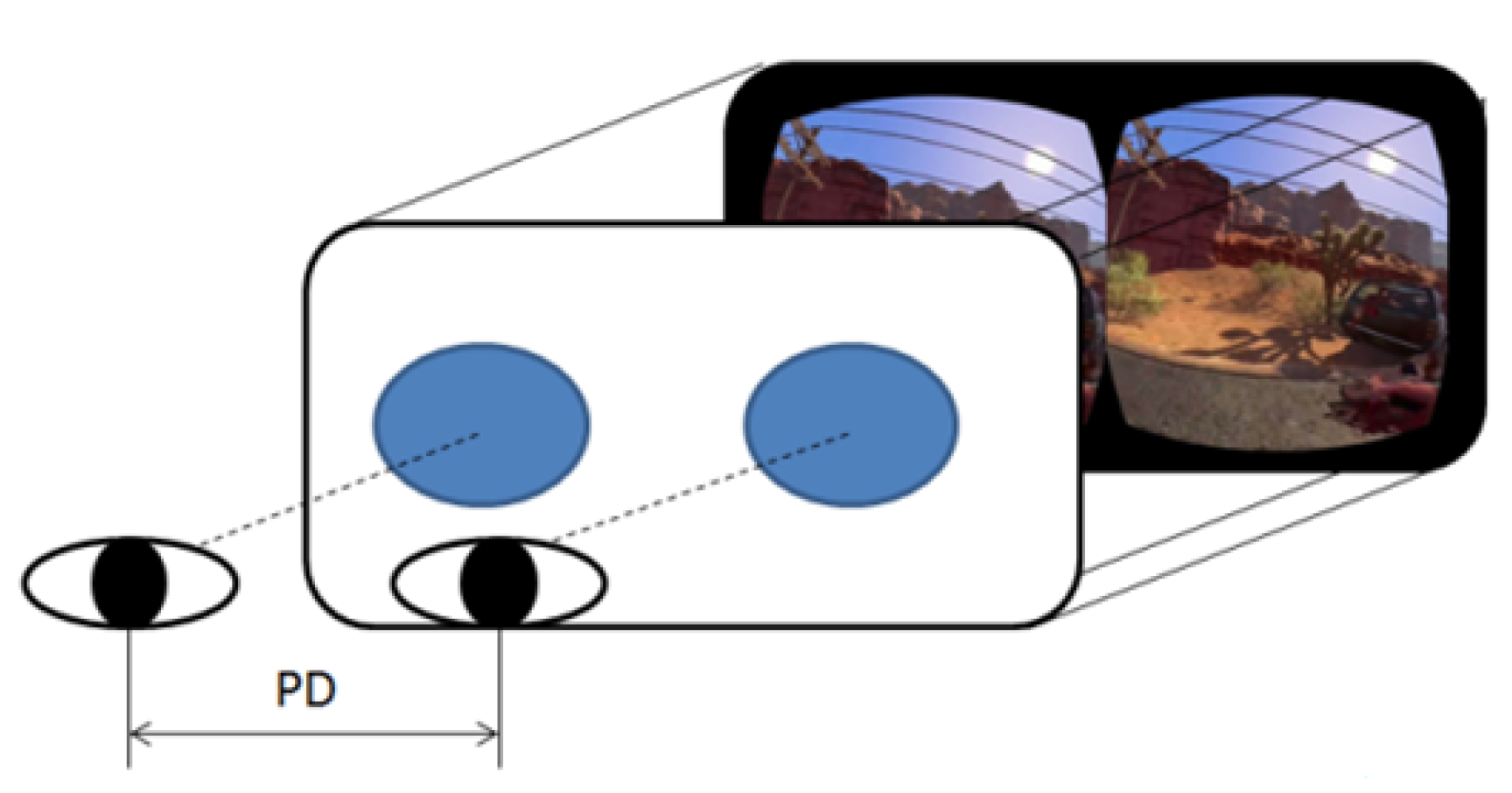
2. Monocular System
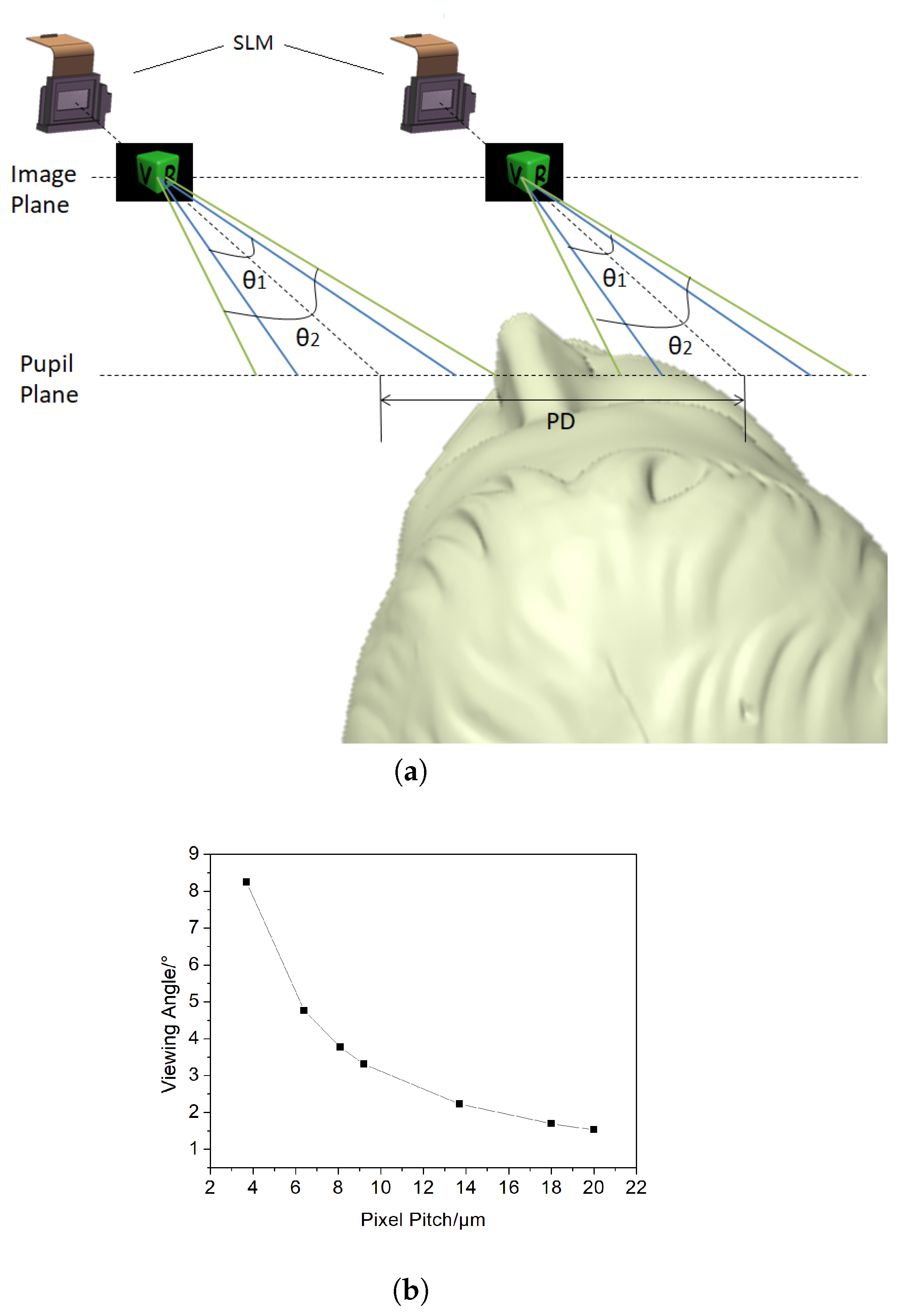
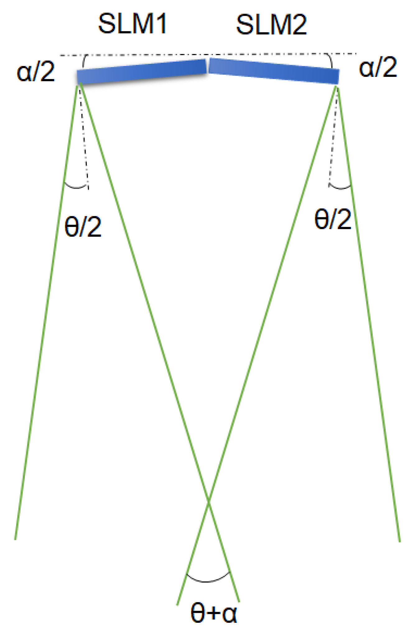
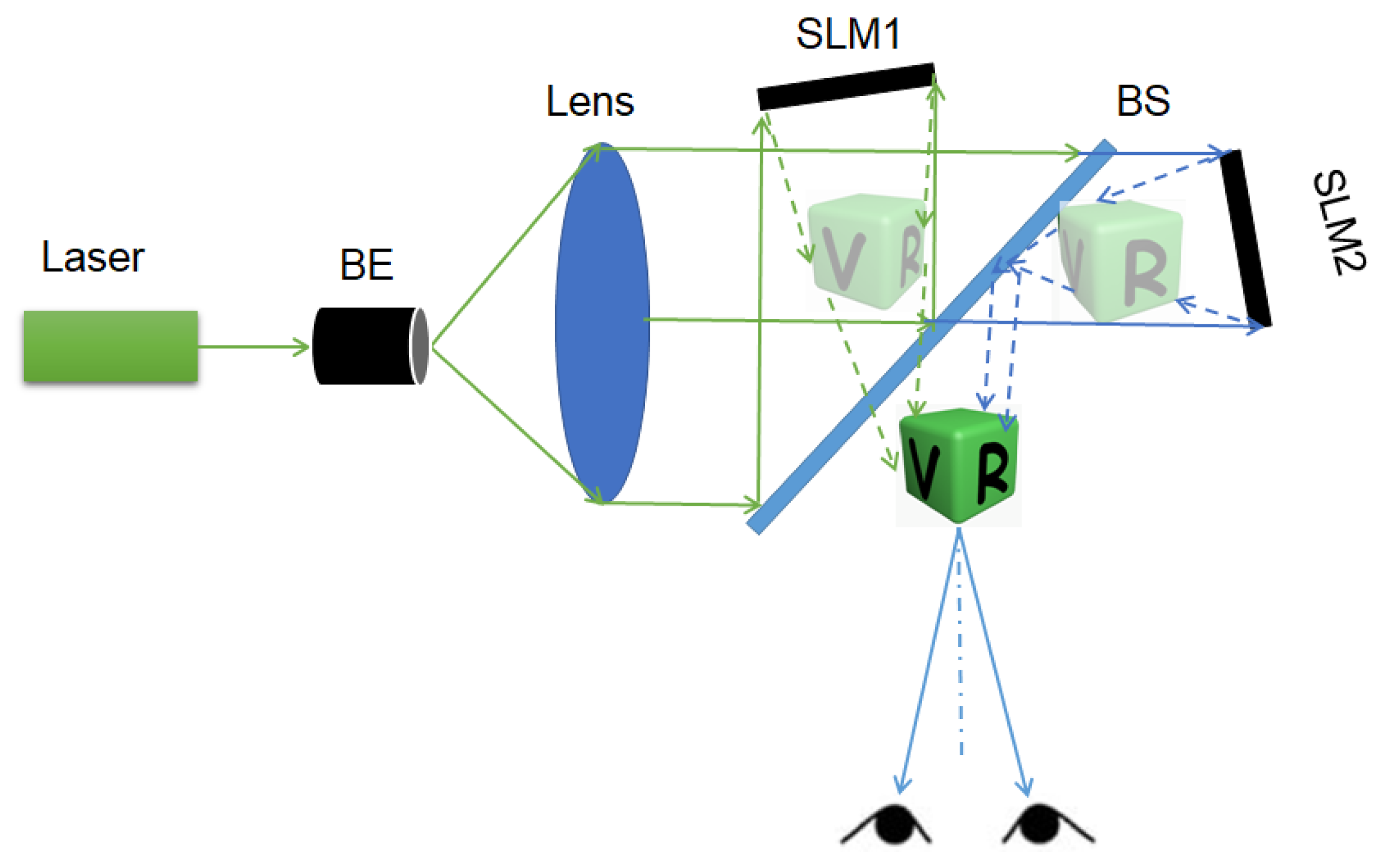
3. Binocular System
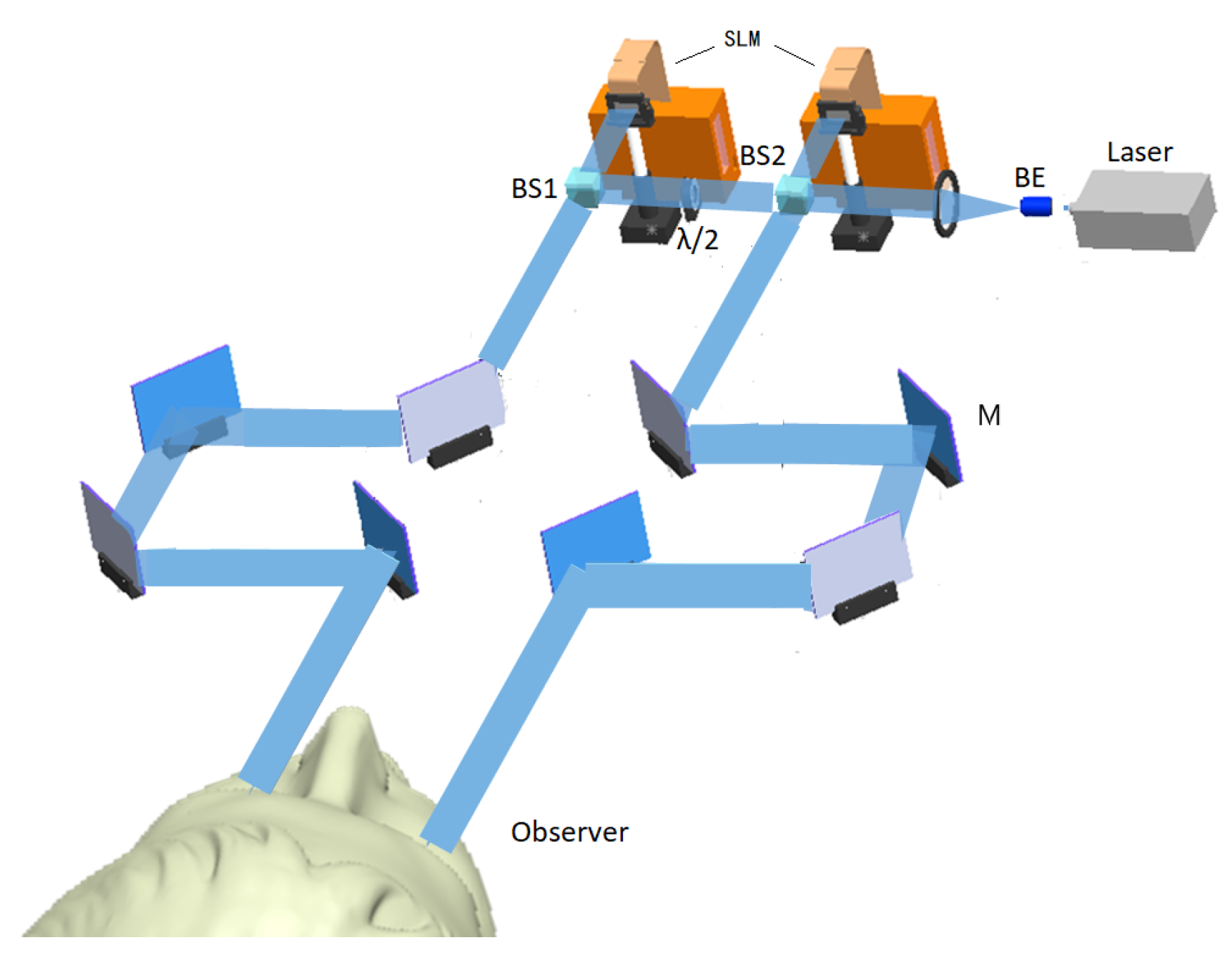
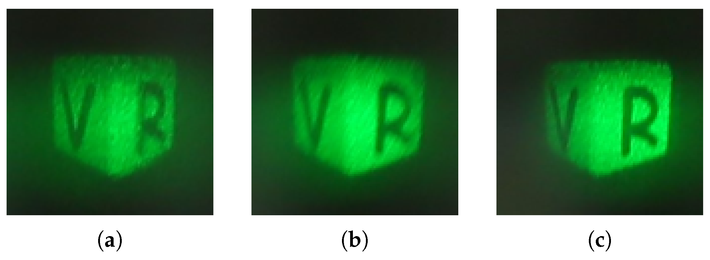
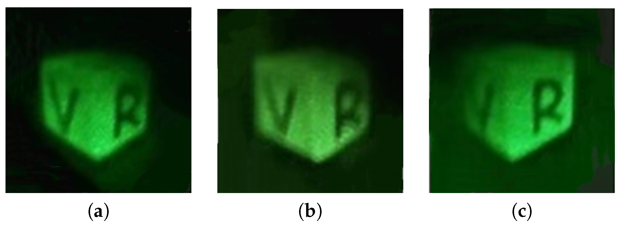
4. Experiments and Results
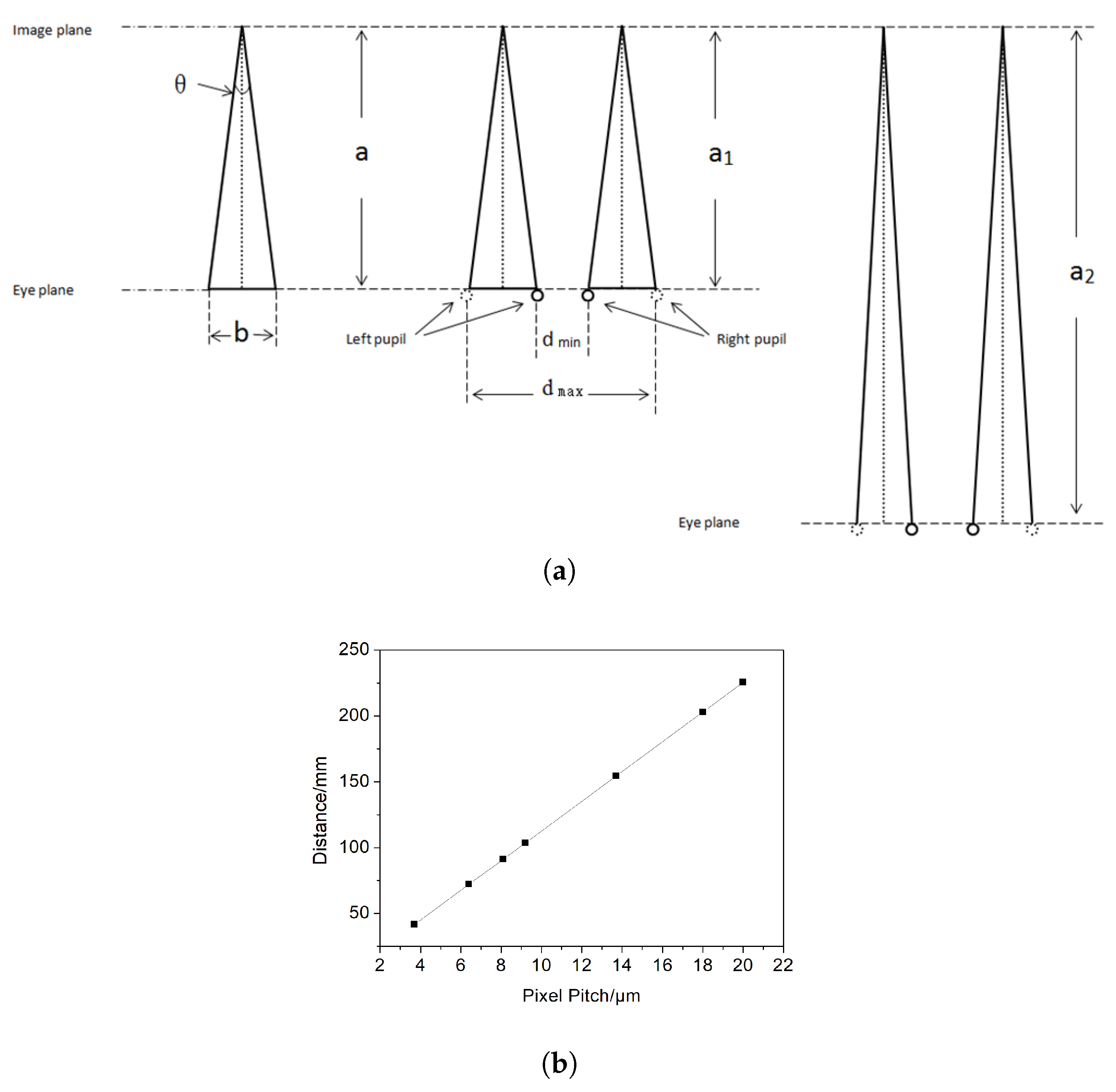
5. Feasibility Analysis
6. Conclusions
Author Contributions
Funding
Conflicts of Interest
References
- Zhao, X.P. Summarize of virtual reality. Chin. Sci. 2009, 39, 2–26. [Google Scholar]
- Russo, J.M.; Dimov, F.; Padiyar, J.; Coe-Sullivan, S. Mass production of holographic transparent components for augmented and virtual reality applications. Light Energy Environ. 2017. [Google Scholar] [CrossRef]
- Yano, S.; Emoto, M.; Mitsuhashi, T. Two factors in visual fatigue caused by stereoscopic HDTV images. Displays 2004, 25, 141–150. [Google Scholar] [CrossRef]
- Maimone, A.; Wetzstein, G.; Hirsch, M.; Lanman, D.; Raskar, R.; Fuchs, H. Focus 3D: Compressive accommodation display. ACM Trans. Graph. 2013, 32, 1–13. [Google Scholar] [CrossRef]
- Deng, H.; Wang, Q.H.; Luo, C.G.; Liu, C.L.; Li, C. Accommodation and convergence in integral imaging 3D display. J. SID 2014, 22, 158–162. [Google Scholar] [CrossRef]
- Hiura, H.; Mishina, T.; Arai, J.; Iwadate, Y. Accommodation response measurements for integral 3D image. Proc. SPIE 2014, 9011. [Google Scholar] [CrossRef]
- Moon, E.; Kim, M.; Roh, J.; Kim, H.; Hahn, J. Holographic head-mounted display with RGB light emitting diode light source. Opt. Express 2014, 22, 6526–6534. [Google Scholar] [CrossRef]
- Yeom, H.; Kim, H.; Kim, S.; Zhang, H.; Li, B.; Ji, Y.; Kim, S.; Park, J. 3D holographic head mounted display using holographic optical elements with astigmatism aberration compensation. Opt. Express 2015, 23, 32025–32034. [Google Scholar] [CrossRef]
- Han, J.; Liu, J.; Yao, X.; Wang, Y. Portable waveguide display system with a large field of view by integrating free-form elements and volume holograms. Opt. Express 2015, 23, 3534–3549. [Google Scholar] [CrossRef]
- Piao, M.L.; Wu, H.Y.; Kim, N. Holographic projection head mounted display with transparent volume hologram. Imaging Appl. Opt. Congress 2016. [Google Scholar] [CrossRef]
- Galeotti, J.M.; Siegel, M.; Stetten, G. Real-time tomographic holography for augmented reality. Opt. Lett. 2010, 35, 2352–2354. [Google Scholar] [CrossRef] [PubMed]
- Kim, H.E.; Kim, N.; Song, H.; Lee, H.S.; Park, J.H. Three-dimensional holographic display using active shutter for head mounted display application. Proc. SPIE 2011, 7863. [Google Scholar] [CrossRef]
- Piao, J.; Li, G.; Piao, M.; Kim, N. Full Color Holographic Optical Element Fabrication for Waveguide-type Head Mounted Display Using Photopolymer. J. Opt. Soc. Korea 2013, 17, 242–248. [Google Scholar] [CrossRef] [Green Version]
- Li, G.; Lee, D.; Jeong, Y.; Cho, J.; Lee, B. Holographic display for see-through augmented reality using mirror-lens holographic optical element. Opt. Lett. 2016, 41, 2486–2489. [Google Scholar] [CrossRef] [PubMed]
- Hong, J.; Li, G.; Lee, B. See-through optical combiner for augmented reality head-mounted display: index-matched anisotropic crystal lens. Sci. Rep. 2017, 7, 2753. [Google Scholar] [CrossRef] [PubMed] [Green Version]
- Sun, P.; Chang, S.; Liu, S.; Tao, X.; Wang, C.; Zheng, Z. Holographic near-eye display system based on double-convergence light Gerchberg-Saxton algorithm. Opt. Express 2018, 26, 10140–10151. [Google Scholar] [CrossRef]
- Hong, J.; Kim, Y.; Hong, S.; Shin, C.; Kang, H. Near-eye foveated holographic display. Imaging Appl. Opt. 2018. [Google Scholar] [CrossRef]
- Gang, J. Three-dimensional display technologies. Adv. Opt. Photonics 2013, 5, 456–535. [Google Scholar] [CrossRef] [Green Version]
- Hiura, H.; Mishina, T.; Arai, J.; Iwadate, Y. Anisotropic leaky-mode modulator for holographic video displays. Nature 2013, 498, 313. [Google Scholar]
- Onural, B.; Yaras, F.; Kang, H. Digital holographic threedimensional video displays. Proc. IEEE 2011, 99, 576–589. [Google Scholar] [CrossRef]
- Hiura, H.; Mishina, T.; Arai, J.; Iwadate, Y. Wide viewing angle dynamic holographic stereogram with a curved array of spatial light modulators. Opt. Express 2008, 16, 12372–12386. [Google Scholar]
- Nanette, S.; Leslie, S. Basic Photographic Materials and Processes; Taylor and Francis: Abingdon, UK, 2009; Volume 110, ISBN 978-0-240-80984-7. [Google Scholar]
- Zeng, Z.; Zheng, H.; Yu, Y.; Asundi, A.K.; Valyukh, S. Full-color holographic display with increased-viewing-angle. Appl. Opt. 2017, 56, 112–120. [Google Scholar] [CrossRef] [PubMed]


© 2019 by the authors. Licensee MDPI, Basel, Switzerland. This article is an open access article distributed under the terms and conditions of the Creative Commons Attribution (CC BY) license (http://creativecommons.org/licenses/by/4.0/).
Share and Cite
Gao, H.; Xu, F.; Liu, J.; Dai, Z.; Zhou, W.; Li, S.; Yu, Y.; Zheng, H. Holographic Three-Dimensional Virtual Reality and Augmented Reality Display Based on 4K-Spatial Light Modulators. Appl. Sci. 2019, 9, 1182. https://doi.org/10.3390/app9061182
Gao H, Xu F, Liu J, Dai Z, Zhou W, Li S, Yu Y, Zheng H. Holographic Three-Dimensional Virtual Reality and Augmented Reality Display Based on 4K-Spatial Light Modulators. Applied Sciences. 2019; 9(6):1182. https://doi.org/10.3390/app9061182
Chicago/Turabian StyleGao, Hongyue, Fan Xu, Jicheng Liu, Zehang Dai, Wen Zhou, Suna Li, Yingjie Yu, and Huadong Zheng. 2019. "Holographic Three-Dimensional Virtual Reality and Augmented Reality Display Based on 4K-Spatial Light Modulators" Applied Sciences 9, no. 6: 1182. https://doi.org/10.3390/app9061182