Mechanical Construction and Propulsion Analysis of a Rescue Underwater Robot in the case of Drowning Persons


Department of Mechanical and Aerospace Engineering, Politecnico di Torino, 10129 Turin, Italy
*
Author to whom correspondence should be addressed.
Appl. Sci. 2018, 8(5), 693; https://doi.org/10.3390/app8050693
Submission received: 13 February 2018
/
Revised: 4 April 2018
/
Accepted: 26 April 2018
/
Published: 30 April 2018
(This article belongs to the Section Mechanical Engineering)
Abstract
:Featured Application
The proposed device can be adopted on beaches and on board boats to support rescue operations.
Abstract
This paper presents the design of an unmanned and tele-operated robotized life-saving system aimed to work as a recovery tool in case of water-related disasters. The device is designed to save people in distress in the water, either conscious or unconscious, without exposing the rescuer’s life to risk. The data of in water accidents show that the greatest number of casualties occurs because of dangerous predicaments conducted by people who want to save other lives. All present solutions are based on aerial, surface or submarine systems needing a crew and able to save only conscious people. This paper intends to fill this gap in the literature by analyzing the main critical issues in the design of a marine autonomous rescue vehicle in terms of performance, capabilities of maneuver in rough sea conditions and the costs. The proposed robot is fully electric and tele-manipulated, from the shore in case of accidents near dry land, or directly from boats or helicopters if drowning is occurring in the open sea. The paper demonstrates the feasibility of a system and its readiness for prototyping phases while presenting a trade-off and cost analysis between six different configurations as well as illustrating in detail the design of the selected layout. The motivations behind the choice of diving strategy to tackle rough sea conditions are described along with the design and the numerical validations of the hydroplane and propulsion systems.
1. Introduction
The adoption of autonomous systems and mobile robots has witnessed a steady growth in several fields such as industrial automation, inspection of structures, the space industry, as well as healthcare and domestic services. Typically, the choice of robotized solutions is motivated by the need to tackle challenging or dangerous tasks in hazardous environments such as the inspection of nuclear plants [1] or the detection and disposal of explosive devices for civil or military operations [2] but it is also dictated by the demand of accuracy, repeatability and efficiency in tasks that can be highly time consuming, costly, and labor intensive such as pipe-lining, data collection, model digitizing, together with anomaly and defect detection in structures [3,4]. Lately, the research has been geared also to the development of marine robotic systems, as some aquatic operations are very difficult for human capabilities or unsafe. A big effort has been aimed at proposing new designs of underwater autonomous vehicles [5], also exploiting bio-inspired principles, such as octopus [6], cephalopod [7], and turtle [8] inspired robots. Sectors like oceanographic science, hydrography mapping, sea exploration, and marine archeology get great benefit from the adoption of unmanned marine robotized vehicles allowing difficult tasks to be tackled like seabed inspection or search and rescue operations [9,10,11,12,13]. In particular, the study in the latter field has been motivated by the high number of sea accidents globally recorded: with around 372,000 deaths counted every year [14], drowning still represents the second highest cause of unintentional death in the world and the 20% of surviving people suffer severe and permanent brain damage, mostly because the rescue occurs too late to keep brain functions unaltered. Moreover, the data show that a great part of trained rescuers or would be rescuers lose their lives or suffer serious injuries trying to save other people, thus there arises a need for solutions to support rescue operations. The main solutions present in literature are classified in aerial, surface, and underwater categories. Aerial solutions are designed to work in bad weather conditions and adopt a lifebuoy or a stretcher hung from the vehicle to aid people in distress [15]. A new perspective is given by the adoption of ekranoplans, vehicles able to fly at only a few meters above the water surface, thanks to the exploitation of the ground effect [16]. Surface rescue vehicles are strongly limited by the poor capability of handling in rough sea conditions. In this category, a solution that is experiencing particular improvement and can be effective in aquatic rescue is represented by personal watercrafts [17,18]. Underwater systems have been presented in the last decades but their spread is still limited due to high costs, maintenance, size, and weight [19,20,21]. All these solutions need a crew to perform the recovery operations and are effective only for conscious people. This paper aims to fill the lack of literature for autonomous marine rescue vehicles presenting a patented device [22] designed to save conscious and unconscious people in distress in the water without the help of a crew and with the capability of maneuver and operations even in the case of a rough sea. The proposed robot is based on an electric powered tele-operated device in the shape of a stretcher that can be controlled from a maximum distance of 400 m from the shore or directly from boats and helicopters if the drowning is occurring in open sea. The solution to tackle rough sea conditions is to move the robot underwater to minimize the effects of the waves on the stability of the vehicle. The choice is motivated also by the statistics stating that most rescuing is performed when the victim is already under the water surface. The sequence of rescuing operations is the following: the robot is thrown in the water, it dives underwater according to a full dynamic diving strategy and localizes the victim with a camera and a temperature and infrared sensor before emerging on the water surface hosting the victim on board.
The paper illustrates a technical and cost trade-off analysis between six different configurations and describes in detail the selected one. The motivations behind the choice of a full dynamic diving strategy are explained along with the design of the hydroplanes, the propulsion system, and the electric and storage equipment. The correctness of the design approach is demonstrated with numerical simulations. Localization and remote manipulation strategies are illustrated in the final part. The device is presented as a tele-operated robot but there are no limitations in updating it in a semi-autonomous or autonomous operating system.
2. Rescue Strategy
The most common scenarios where drownings occur are the following: (a) beaches characterized by high numbers of drowning; (b) open sea, where high hazardous conditions complicate the operations, and (c) flooding, where it is not easy to reach people and it is likely to have to deal with narrow spaces. Regardless of the scenario, the main causes of death are hypothermia and drowning. Referring to hypothermia, different times can elapse until death depending on the water temperature. At a temperature of about 2 °C, the time for death is of the order 35–40 min [23]. In the case of drowning, a person in distress in the water suffers the process in five different phases that are depicted in Figure 1. It has been demonstrated that if the person in distress is pulled out of the water at the beginning of the fourth phase, the victim starts re-breathing by him/herself without suffering any brain damage. The time interval up to the fourth phase has a duration of 3–5 min [23].
Wearing a floating device can improve considerably the chances of successful rescue. The combination of the first four drowning phases in Figure 1 and the presence of the floating device lead to four different situations: (a) vertical position with the head out of the water (the victim is conscious and wearing a floating device); (b) horizontal supine position on the water surface (the victim is unconscious and wearing a floating device); (c) battler position on the water surface (the victim is unconscious and is wearing a floating device that does not allow the victim to lie face up) and (d) battler position under water (the victim is conscious, and does not wear any floating device). It is commonly recognized that for biological reasons, a horizontal position during the rescue maneuver is the only safe alternative. Thus, the most efficient rescue is operated from underwater where the robot can maintain the desired trim also in the case of rough sea and unconscious victims can be saved more easily. These considerations along with the necessity to move underwater to face rough sea motivate accurate selection of the diving strategy to drive the robot effectively. Referring to the field of submersible devices, there are two ways of diving a system: static and dynamic diving. The former is based on changing the buoyancy of the vessel by varying its weight, i.e., by letting water enter into ballast tanks. The latter exploits the motion of two horizontal axis hydroplanes to control the vertical position of the system. These elements can develop lift or duck force, provided that they are orientated with a given angle of attack with respect to water and that the vessel is moving with a certain velocity [24]. To achieve static diving, a variation of the weight with respect to lifting is followed, while in the case of dynamic diving, no additional weights, or, on the contrary, no reduction in lift, is required. Static diving allows stopping the robot underwater but the water in the ballast tanks increases the total mass of the device at the expense of control capability and room for payload. Dynamic diving, on the other hand, can be performed in two different configurations: normal and full. In normal dynamic diving, the water level in the ballast tank is set during the first dive, so that, as neutral buoyancy is obtained, the hydroplanes can be maintained in a nearly horizontal position, once having achieved the required depth. This concept is commonly adopted for submarines, where a combination of sufficient speed and sufficiently large hydroplanes is required. By converse, the full strategy allows devices to have a positive buoyancy: if control is lost, floating up to the water surface naturally occurs. The sum of the lift developed by the hydroplanes with the weight and Archimedes’ lift of the device has to be zero. To this end, the hydroplanes have to be tilted also when the required depth is reached. Both normal and full configurations do not allow maintainenance of the desired static underwater trim when the propulsive engines are stopped, as velocity is the necessary condition for the hydroplanes to develop the required lift. Figure 2 reports the hydroplane tilting sequence for normal (a) and full (b) dynamic diving. The first step of the normal approach (a.1) is to rotate upward the aft plane so that the stern of the vehicle is also forced upward. At the same moment, the fore control surfaces are tilted downwards, forcing the bow of the vessel down. During the dive (a.2), the aft plane is set back to the neutral position: in this case, the control of the diving angle is obtained only through the fore hydroplane. Finally, when approaching the required depth (a.3), the aft planes are rotated down and the fore up. In the last phase (a.4), the aft plane is neutral while the fore is controlled to regulate the velocity of the robot. The path is not linear and the device is not in a horizontal position during diving. On the contrary, during full dynamic diving the two planes are always tilted (b.1 and b.2), the path of diving is linear and the device is always in a horizontal position.
Both the static and diving strategies are investigated and considered in the trade-off analysis presented in the next section.
3. Architecture of the Robot
The proposed device is designed to carry a minimum payload of 75 kg. The victim is approached from underwater and then helped into the net when the robot emerges on the surface. Then the mission can stop, wait for a support ship or a helicopter, or can continue, bringing the victim to a safer place. Since the water could be dirty and opaque, the robot would be equipped with a set of sensors (350 lumens search LED light, infrared and temperature sensor etc.) to facilitate the localization procedure. This issue is beyond the aim of this paper. The maximum speed of the robot is 10 kn (5.15 m/s). The minimum duration of the mission is 15 min and the operations may be repeated many times, accounting for the possibility of missing the victim at first attempt. The device has to be able to stop and maintain a fixed relative position with respect to the body. Furthermore, the person should acquire a horizontal position once saved, as it is medically demonstrated that, in this way, the risk of further injuries is minimized. Owing to these requirements, six different solutions are proposed in this section. Every configuration is composed of a stretcher supported by two lateral hulls. Two propellers (1 in Figure 3) are positioned under the hulls to avoid contact with the victim. Since the robot is remotely controlled, it is sufficient to drive the propellers with different velocities to make the system yaw in the desired direction. This solution is more compact from the construction point of view and effective also in the case of low speed maneuvering if compared with a configuration based on a single propulsion system combined with a rudder. The six architectures are illustrated in Figure 3 where (a), (b), (c), and (d) are designed for the static diving strategy while (e) and (f) exploit the normal and full dynamic diving approach respectively. The final selected configuration is (f).
Solution (a): the vertical motion is provided by filling and emptying four diving chambers (3) (two per each hull) with two reversible electro-pumps (2). The amount of air needed to fill or empty the chambers is taken over the surface of water by means of two snorkels (11). Motors supplying propellers, electro-pumps, batteries, and electronic devices are contained in the paraboloid heads of the hulls, separated by the diving chambers through watertight plates. The rescue method is as follows: the robot localizes and reaches the victim using the horizontal propellers (1), immerses by filling the diving chambers with water, moves right under the person by switching on the propellers again, and then emerges vertically by emptying the diving chambers.
Solution (b): the concept is based on the same idea and the same rescue method of (a) but aims at reducing the weight and mass moments of inertia. The cylindrical hulls here do not take up the entire length of the robot. One diving chamber per hull (3) is present and thus the control of pitch movement has to be performed with additional rudders (not illustrated in the Figure).
Solution (c): the robot can immerse by changing its volume with the deformable hulls (4). The device can move both underwater and at the surface level during the outward phase and only at the surface level when the victim is onboard. The hull is conceived to be an ellipse during the outward phase (c.1), with an eccentricity that will depend on the decided trim (underwater or displacing) and a cylinder in the most loaded condition (c.2), i.e., when the victim is onboard. The solution presents problems of dimensions, repeatability, and fatigue of the hulls.
Solution (d): the device is equipped with cylindrical vessels storing compressed air used to inflate two dinghies responsible for the device trim. The robot can proceed during the outward phase with an underwater or a displacing trim, having already inflated the corresponding dinghies prior to the mission start. Once identified and having reached the position of the victim, the device further dives by simply deflating the dinghies through a vacuum generator (5). Then the dinghies are inflated so as to provide the requested lift and complete the mission. This solution presents problems of reliability, cost, and issues connected with the movement of a pressure tank in seawater.
Solution (e): this solution presents a reduced area exposed to water, with short hulls and a grid-shaped lateral structure to have more controllability in the case of strong water currents. The system is equipped with four vertical propellers for descent and ascent operations. Pumps and chambers (7) devoted to the storage of water regulate the mass of the robot to enable it to be always in underwater equilibrium trim. The robot is thrown into the water with the water tanks initially empty. Horizontal propellers start to rotate, while the action of the pumps guarantees the desired underwater equilibrium. Once this is obtained, the vehicle moves horizontally and vertical propellers (6) are switched on to provide a downward motion to position the robot right under the victim; simultaneously, electro-pumps are activated with an outgoing flow in order to reduce the weight of the system, since the person is going to be carried, while the depth is still controlled by vertical propellers. Then, the rotation of the propellers is reversed and the person is carried, while electro-pumps carry on pushing out water until an equilibrium condition is reached. After the equilibrium trim is achieved, both pumps and vertical propellers are switched off.
Solution (f): the architecture is based on a structure in the shape of a stretcher consisting of two cylindrical hulls (4), a net, two transversal spacers, two propellers, and two hydroplanes (8). PVC is adopted because it is cheaper and lighter than metal and with good commercial availability. For each hull, two aluminum heads with welded aluminum appendages are present. The hydroplanes are located between the two hulls, supported by two shafts. Motors supplying propellers, batteries, and electronic devices are contained in the hulls. The search light is installed together with the camera on the front transversal spacer.
Two hydroplanes are adopted instead of the four commonly installed in submarines to reduce the overall dimensions of the configuration. Figure 4 reports the main dimensions of the robot (upper (a), lateral (b), and rear view (c)). The rescuing bed is a net made of the material used for the stretchers (9 in Figure 3), which is a particular polyester covered by a PVC (Polyvinyl Chloride) layer. It is connected to the main frame at several points, wrapping both the longitudinal beams and the transversal spacers. Two aluminum longitudinal runners are located inside the hulls and welded to the aluminum heads to support the battery packs and electronics.
The main properties of the presented configurations are reported in Table 1. All solutions have approximately the same size, only (c) presents a bigger width due to its deformable hulls. As far as engine power and battery weight is concerned, the worst solutions are (c) and (f). The number of actuators is high for (e) and low for (c) and (f). Considering the mass moments of inertia, which also affect the governance of the system, the worst solutions are (a), (b), and (e), while the best is (d). The only configurations allowing a carrying capacity to be obtained higher than 75 kg are (a), (b), and (f) while only (d) is limited in the number of attempts, due to the quantity of compressed air on board. This number is infinite for all systems, apart from (c).
Solution (c) is set apart because of the low repeatability, poor performance in displacing conditions, and the enormous hull deformation needed to immerse the device. Configuration (d) is discarded because of the limited number of trials, (e) because of the high mass moments of inertia, low maximum speed, and high number of actuators, and (b) because of the necessity of adding further components to control the pitch motion. The final choice of (f) at the expense of (a) is based on the diving strategy, the number of actuators and the load capacity of the system. Full dynamic diving is selected to obtain an appreciable positive buoyancy. The robot has a static lift higher than its unladen weight because immersion can be provided by the vertical force generated by the rudders when inclined. Therefore, when no person is on board and the hydroplanes are in a neutral position, the vehicle has a displacement trim. Moreover, hydroplanes can exert a vertical force only if the system is moving forward, thanks to the action of the propellers. Since the weight of the robot and the person are comparable, the total Archimedes lift of the system has to be high enough to allow a displacing trim during the returning phase, i.e., when the victim has already been hoisted on board. The drawback of this approach lies in the fact that, during the outward phase, a substantial difference between the total lift and the unladen weight of the vessel causes the hydroplanes to work continuously during the approaching phase of the mission.
4. Control, Localization, and Communication Strategy
The control scheme of the robot is illustrated in Figure 5. The DSP (Digital Signal Processor)-based electronic control unit manages the information from the receiver of the tele-manipulation to generate the correct references for the power drivers of the propeller and the hydroplane. The selected motors for the propulsion are indicated in the section devoted to the propulsion design, while each hydroplane is actuated with a Direct Current (DC) electric motor supplied at 48 V and coupled with a 9.3:1 reducer for a total power of 960 W, a nominal speed of 400 rpm and a nominal torque of 68.7 Nm. The motors and the electronic boards are supplied by the battery pack located in the hulls.
The localization of the victim is performed by combining the information coming from a camera located in the front of the robot, a temperature sensor providing a temperature map of the robot surroundings, and an infrared sensor. The real-time data of these devices are processed onboard, compressed, and transmitted to the remote robot operator who drives the propellers, the rudders, and the orientation of the camera accordingly.
The communication between the remote operator and the robot is performed by exploiting the buoyant communication system illustrated in Figure 6. The information coming from sensors located on the robot are compressed on board and sent through a data cable (2) from a transceiver (1) to an antenna (4) located on a buoy (3). A second antenna is close to the operator and receives the data that are processed by a remote transceiver (5) and sent to the operator (6). The acquired data are used by the operator to drive the robot in the approach, rescue, and return phases. Since the robot is designed to work at a maximum depth of 1.5 m from the water surface, the buoyant communication solution can be considered simple and highly reliable. Nevertheless, other possibilities presented in the literature can be investigated, like active and passive sonar communication systems and direct underwater communication [25,26,27,28].
5. Cost Analysis
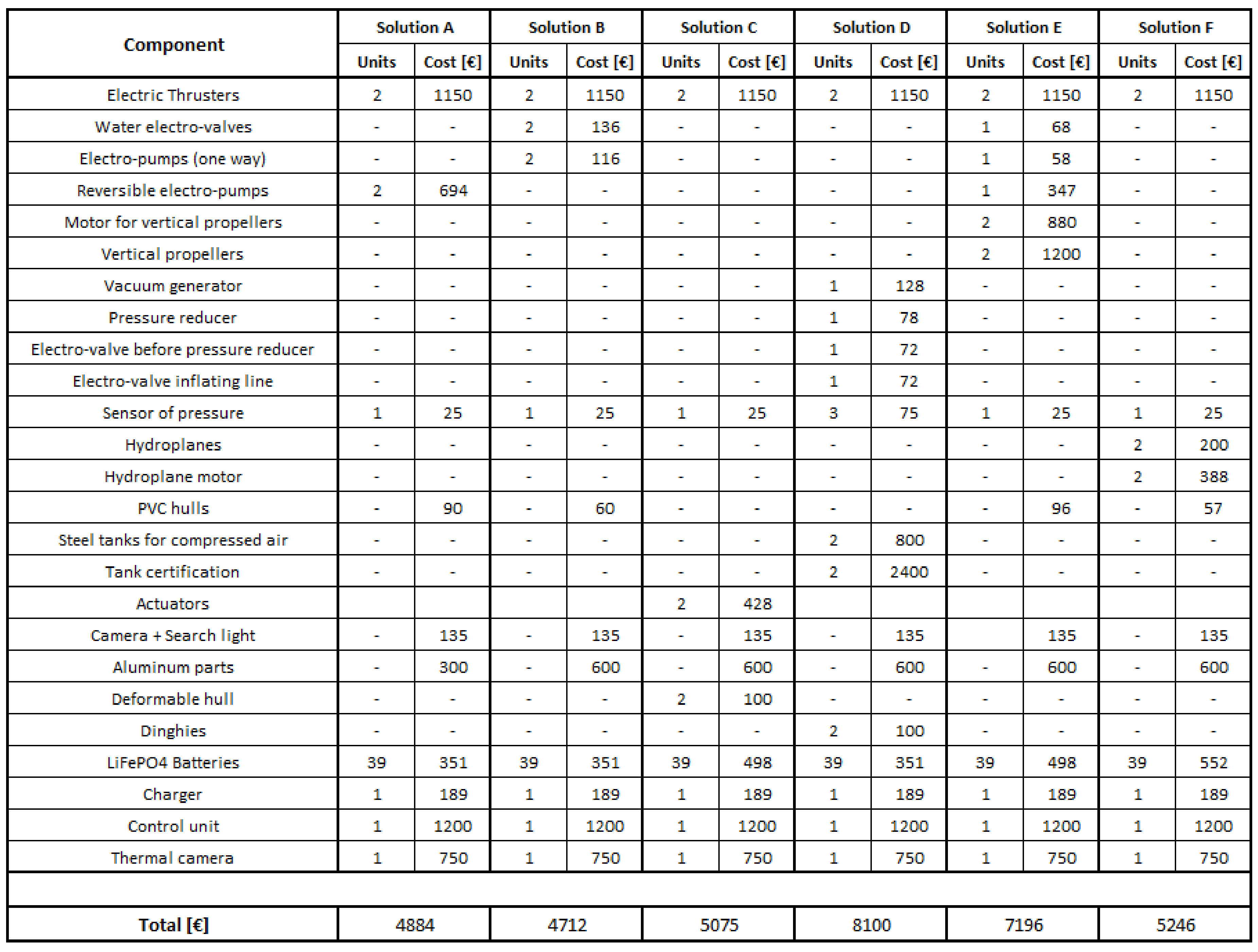
A further comparison of the proposed solutions has been conducted in terms of direct cost of the materials where economies of scale are not considered (Figure 7). All the solutions are equipped with two electric thrusters (3 kW at 48 V). In addition, (Solution A) adopts a couple of reversible electro pumps (150 W at 24 V), (Solution B) two water electro-valves and two one-way electro-pumps (132 W at 12 V), (Solution C) two linear actuators (350 W at 24 V), (Solution D) a vacuum generator, a pressure reducer, an electro-valve before pressure reducer, an electro-valve inflating line, two tanks to be certified and a couple of dinghies, (Solution E) a water electro-valve, a one-way electro-pump, a reversible electro-pump, two electric motors (400 W at 24 V) for the two vertical propellers, and (Solution F) two hydroplanes with the related electric motors (1.8 kW at 48 V). The battery pack cost difference between the solutions is due to the different power and thus to the different battery nominal capacity required by each configuration.
6. Hydroplane and Propulsion System Design
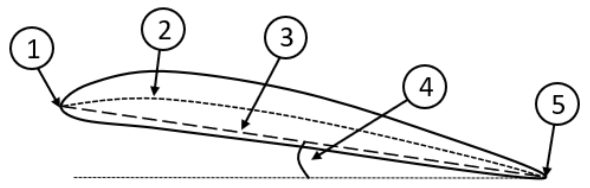
The design of the hydroplanes is based on the selection of the wing airfoil, which has to be symmetric since the lift is developed in both senses. The main parameters of a typical airfoil are illustrated in Figure 8 where the medium line (2) is the line equidistant, in every point, from the belly and back of the profile and the chord (3) is the line that joints the leading edge (1) and the trailing one (4). In a symmetric section profile, chord and medium lines are coincident. The inclination of the chord with respect to the water surface is the angle of attack (5) [29]. The most commonly adopted airfoils in literature are NACA10 and their derivatives, first developed in the 1940s for airplanes designed both for subsonic and supersonic speed. Among these, the NACA 0015 was selected being commonly used in aeronautic and naval field applications [29,30,31,32,33].
The meaning of the four digits of NACA 0015 profile is: 0: maximum ordinate of the medium line, with respect to the chord, expressed as a percentage of the chord itself; 0: position, along the chord, of the maximum ordinate of the medium line, expressed in tenths of the chord length; 15: maximum value of thickness distribution, expressed as a percentage of the chord length [29].
The local thickness of the considered airfoil in function of (chord length) and (distance from the leading edge of a point along the chord expressed as a percentage of the chord length) is expressed by
and is plotted in Figure 9.
The NACA0015 reference trend of the lift and drag coefficients as a function of the angle of attack (5 in Figure 8) at varying Reynolds’ number were experimentally measured in the past and can be found in the literature [29,30,31].
The structure of the proposed robot adopts an aft and a stern hydrofoil with the same geometry as illustrated in Figure 4. Fluid-dynamic analyses are conducted in Solidworks Flow Simulation to evaluate the lift and drag force at various angles of attack and longitudinal velocities in the following cases: (a) computation on the aft and stern hydrofoils when located inside the vehicle, (b) computation on the free wing, and (c) computation on the whole vehicle. The simulations of the whole vehicle are performed exploiting a simplified 3D model (Figure 10) to ensure the convergence of the computations and a restrained simulation time. The hulls and the electric thrusters are considered as a unique body with an equivalent geometry. The battery pack, the control modules and the communication devices are installed inside the two hulls and thus they can be neglected in the fluid dynamic analysis. The effects of the communication cable between the robot and the buoy in terms of increased lift and drag force are not taken into account in this simulation.
The mesh adopted for the simulation of the whole vehicle and of the hydrofoil is the same. The volume of the considered fluid is equal to 31 m3 and is divided into 3,118,905 elements with a logarithmic distribution along the three principal axes. The mesh is thicker on the close surroundings of the robot and along the wake, as illustrated in Figure 11, where a 2D mesh representation along the longitudinal axis is reported for the whole vehicle (a) and the free wing (b).
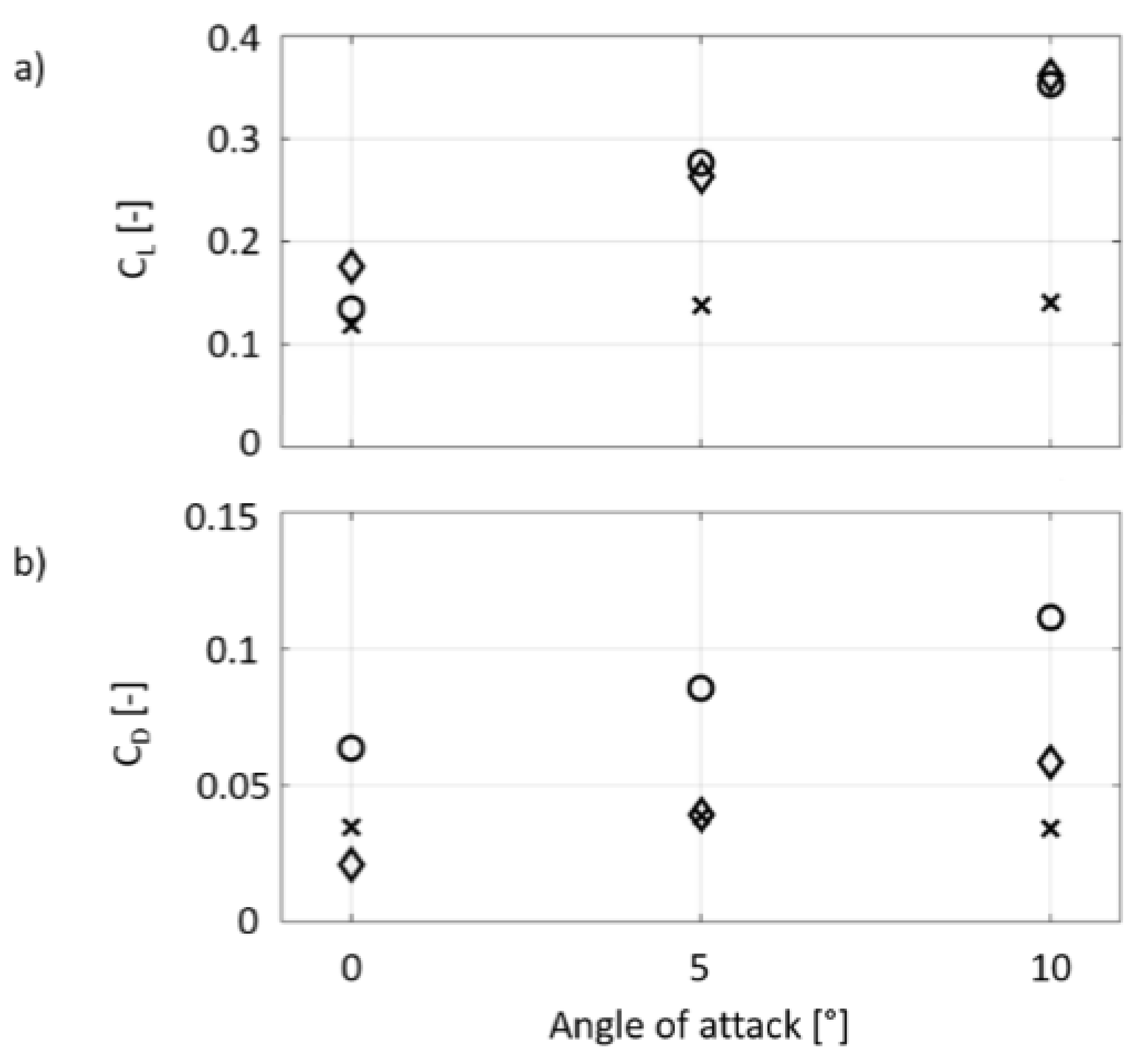
The first part of the simulations is aimed to evaluate and compare the lift () and drag () coefficients of the hydrofoils in the free-flow case and when they are located inside the vehicle. The coefficients are obtained adopting the following definitions:
where is the density of the water, is the velocity of the robot, and is the area of the hydrofoil equal to 0.36 m2.
The results are reported in Figure 12 where and are plotted with the angle of attack ranging from 0 to 10 degrees for the free wing (diamond marker) and for the aft (round marker) and stern (cross marker) hydrofoil when they are located inside the vehicle. In the case of , the behavior of the aft hydrofoil is similar to the free flow configuration, while the stern rudder is less loaded. On the other hand, the value of is close to 0 in the three cases and is higher for the aft hydrofoil.
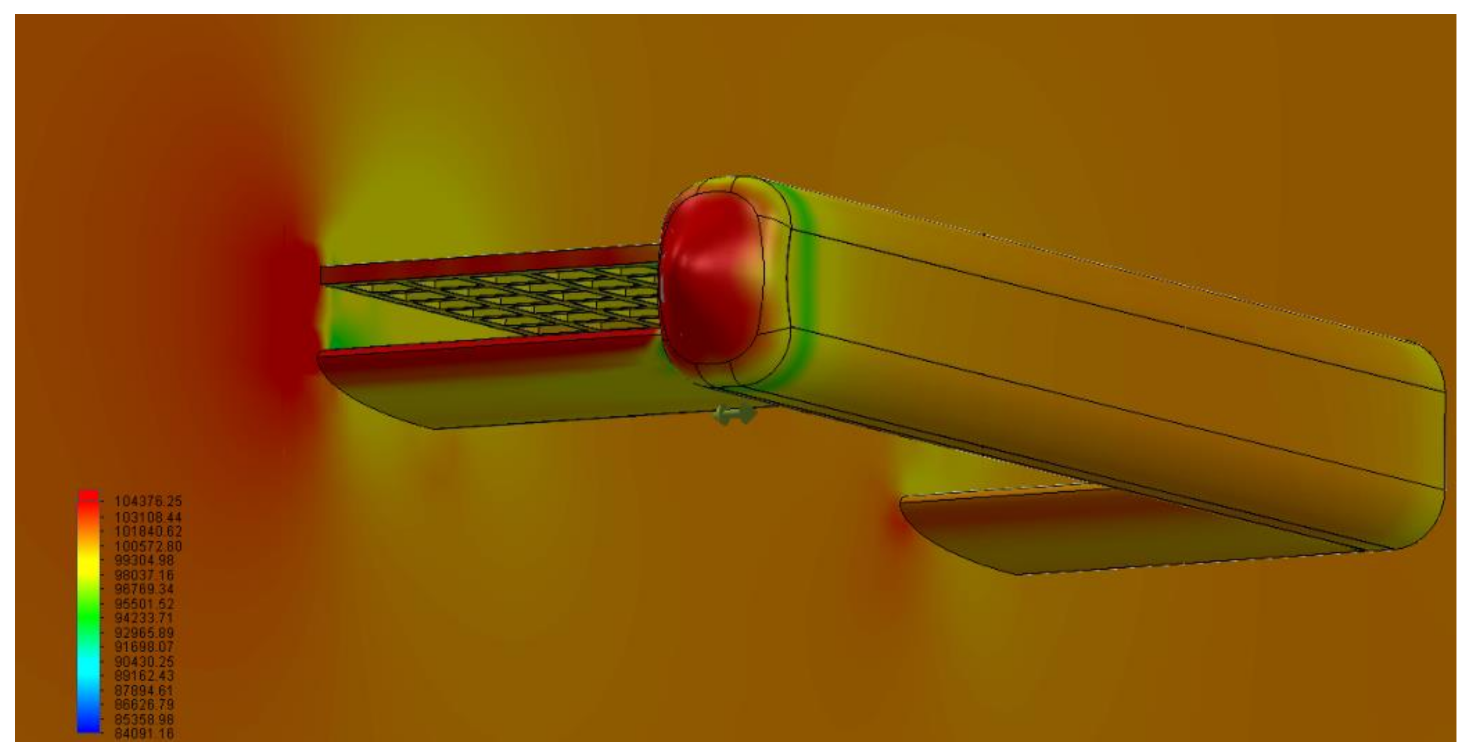
The second part of the analysis is focused on the evaluation of the forces exerted on the whole vehicle. The results of the simulations are reported in Figure 13, where the lift (diamond marker), drag (round marker) and total resulting force (cross marker) are plotted with a velocity ranging from 1 to 5 m/s and in three cases of angle of attack: 0° (a), 5° (b), and 10° (c). The distribution of the pressure on the vehicle and on the cut-plot at the longitudinal symmetry plane is illustrated in Figure 14 in the case of 5 m/s and angle of attack equal to 10°. It is evident that the pressure is more intense on the front part of the vehicle and it is confirmed that the stern hydrofoil is remarkably less loaded than the aft one.
The selected motors for the propulsion of the robot are two electric thrusters with nominal thrust equal to 1650 N (nominal power: 1.5 kW, DC Voltage: 48 V, weight: 7.5 kg), the maximum propulsion force is thus equal to 3300 N. Therefore, the maximum velocity of 5 m/s can be reached when the angle of attack is 0°. Increasing the angle of attack to 5° and 10°, the velocity reduces to 4 m/s and 3.7 m/s respectively as indicated in Figure 13. High values of imply the reduction of the velocity but this does not represent a strong limitation since high angles of attack are required mainly during diving and emerging operations, thus at low velocity.
Considering the characteristics of the propellers and a minimum time of 15 min for rescuing operations, the required capacity of the batteries to supply the electric motors is obtained by
where is the capacity of the battery in Ah required by the electric thrusters, is the power of the electric loads in W, is the working time in h, and is the supply voltage in V. A further amount of energy has to be provided for hydroplane actuation (460 Wh at 48 V), the communication (30 Wh at 24 V obtained and stabilized with a converter from eight series cells of the battery pack) and the control system (6 Wh at 12 V obtained and stabilized with a converter from four series cells of the battery pack). Considering a safety factor of 1.25, the resulting total value of the battery capacity is
LiFePo04 is the selected battery technology. Since the required nominal voltage is 48 V, the battery pack is composed of 39 cells with a nominal voltage of 3.7 V (min: 3.2 V / max: 4.2 V) and a capacity of 15,000 mAh each. The pack is arranged with three parallel strings of 13 cells (3p13s configuration) to provide the correct amount of energy. The camera and the search LED lights are not included in the design of the battery because they are contained in the same package equipped with an integrated battery (3.89 Wh–1050 mAh).
7. Conclusions
The design of a tele-manipulated underwater robot for rescue operations of conscious and unconscious drowning persons has been presented in this paper. The designed robot is fully electric, can be tele-manipulated from 400 m, has a maximum velocity of 10 kn (5.15 m/s), and a minimum autonomy of 15 min. The rescue is performed by throwing the robot in the sea and driving it under the victim to host him/her in the net between the two lateral hulls. The system can be operated even in rough sea conditions thanks to the selected diving strategy. The paper illustrated a trade-off and cost analysis between six different configurations and the design of the main subsystem of the selected architecture: hydroplanes, propellers, electrical and storage equipment. A numerical validation was conducted in Abaqus to validate the design of hydroplane and propulsion systems. The obtained results demonstrate the feasibility of the system and its readiness for the prototyping phases.
Author Contributions
Nicola Amati conceived the proposed robot configurations. Angelo Bonfitto performed the numerical simulations. Both authors wrote the paper.
Acknowledgments
To the memory of Pietro Maggiolini, a model student, a first-class engineer, a hero died to rescue and save three people who were drowning.
Conflicts of Interest
The authors declare no conflict of interest.
References
- Gelhaus, F.E.; Roman, H.T. Robot applications in nuclear power plants. Prog. Nuclear Energy 1990, 23, 1–33. [Google Scholar] [CrossRef]
- Voth, D. A new generation of military robots. IEEE Intell. Syst. 2004, 19, 2–3. [Google Scholar] [CrossRef]
- Almadhoun, R.; Taha, T.; Seneviratne, L.; Dias, J.; Cai, G. A survey on inspection structures using robotic systems. Int. J. Adv. Robot. Syst. 2016, 13. [Google Scholar] [CrossRef]
- Wang, L.; Wang, H. A survey on insulator inspection robots for power transmission lines. In Proceedings of the IEEE 4th International Conference on Applied Robotics for the Power Industry, Jinan, China, 11–13 October 2016. [Google Scholar]
- Mazumdar, A.; Triantafyllou, M.S.; Asada, H.H. Dynamic Analysis and Design of Spheroidal Underwater obots for Precision Multidirectional Maneuvering. IEEE/ASME Trans. Mechatron. 2015, 20, 2890–2902. [Google Scholar] [CrossRef]
- Giorgio-Serchi, F.; Arienti, A.; Corucci, F.; Giorelli, M.; Laschi, C. Hybrid parameter identification of a multi-modal underwater soft robot. Bioinspir. Biomim. 2017, 12, 025007. [Google Scholar] [CrossRef] [PubMed]
- Giorgio-Serchi, F.; Arienti, A.; Laschi, C. Underwater soft-bodied pulsed-jet thrusters: Actuator modeling and performance profiling. Int. J. Robot. Res. 2016, 35, 1308–1329. [Google Scholar] [CrossRef]
- Licht, S.; Polidoro, V.; Flores, M.; Hover, F.S.; Triantafyllou, M.S. Design and projected performance of a flapping foil auv. IEEE J. Ocean. Eng. 2004, 29, 786–794. [Google Scholar] [CrossRef]
- Singh, J.; Gandhi, D.; Sanghani, M.; Robi, P.S.; Dwivedy, S.K. Design and development of underwater robot. In Proceedings of the International Conference on Robotics, Automation, Control and Embedded Systems, RACE 2015, Chennai, India, 18–20 February 2015. [Google Scholar]
- Roman, C.; Mather, R. Autonomous underwater vehicles as tools for deep-submergence archaeology. Proc. Inst. Mech. Eng. Part M J. Eng. Marit. Environ. 2010, 224, 327–340. [Google Scholar] [CrossRef]
- Govindarajan, R.; Arulselvi, S.; Thamarai, P. Underwater robot control systems. Int. J. Sci. Eng. Technol. 2013, 2, 222–224. [Google Scholar]
- Yuh, J. Modeling and control of underwater robot vehicles. IEEE Trans. Syst. Man Cybern. 1990, 20, 1475–1483. [Google Scholar] [CrossRef]
- Fossen, T.I. Guidance and Control of Ocean Vehicles; John Wiley & Sons Ltd.: Hoboken, NJ, USA, 1994. [Google Scholar]
- Meddings, D.; Hyder, A.A.; Ozanne-Smith, J.; Rahman, A. Global Report on Drowning, Preventing a Leading Killer; World Health Organization: Geneva, Switzerland, 2014. [Google Scholar]
- Eurekanetwork. Available online: http://www.eurekanetwork.org/content/e-3931-asarp (accessed on 1 December 2017).
- Taylor, G.K. A practical guide to building ekranoplan (wig) models. In Proceedings of the EAGES 2001 International Ground Effect Symposium, Toulouse, France, 12–15 June 2001. [Google Scholar]
- Young, L.A. Small Autonomous Air/Sea System Concepts for Coast Guard Missions. In Proceedings of the USCG Maritime Domain Awareness Requirements, Capabilities, and Technology (MDA RCT) Forum, Santa Clara, CA, USA, 2 May 2005. [Google Scholar]
- Young, L.A. Future Roles for Autonomous Vertical Lift in Disaster Relief and Emergency Response. In Proceedings of the AHS International Meeting on Advanced Rotorcraft Technology and Life Saving Activities, Nagoya, Japan, 15–17 November 2006. [Google Scholar]
- Mantra–Automated Life-Saving System to Tackle Beach Safety Issues. Available online: http://www.tuvie.com/mantra-automated-life-saving-system-to-tackle-beach-safety-issues/ (accessed on 1 December 2017).
- Submarine Rescue Systems. Available online: http://www.oceanworks.com/ (accessed on 1 December 2017).
- NATO Submarine Rescue System. Available online: http://ismerlo.org/assets/NSRS/nato_srs.htm (accessed on 1 December 2017).
- Amati, N.; Genta, G.; Vaniglia, E.; Bersezio, P. Aquatic Rescue Vehicle. Patent EP28413351A1, 24 April 2012. [Google Scholar]
- Brooks, C.J. Survival in Cold Water; Survival System Limited: 40 Mount Hope Avenue Dartmouth, Canada, 2011. [Google Scholar]
- Burcher, R.; Rydill, L. Concepts in Submarine Design; Cambridge University Press: Cambridge, UK, 1994. [Google Scholar]
- Yusof, M.A.B.; Kabir, S. Underwater communication systems: A review. In Proceedings of the Electromagnetics Research Symposium Proceedings, Marrakesh, Morocco, 20–23 March 2011. [Google Scholar]
- Williams, S.B.; Newman, P.; Rosenblatt, J.; Dissanayake, G.; White, H.D. Autonomous underwater navigation and control. Robotica 2001, 19, 481–496. [Google Scholar] [CrossRef]
- River, D.F.; Bansal, R. Towed antennas for US submarine communications: A historical perspective. IEEE Antennas Propag. Mag. 2004, 46, 23–36. [Google Scholar] [CrossRef]
- Beeman, J.W.; Grant, C.; Haner, P.V. Comparison of three underwater antennas for use in radiotelemetry. N. Am. J. Fish. Manag. 2004, 24, 275–281. [Google Scholar] [CrossRef]
- Abbott, I.H.; Von Doenhoff, A.E. Theory of Wing Sections; Dover Publications: New York, NY, USA, 1959. [Google Scholar]
- NACA0015 Airfoil Tools. Available online: http://airfoiltools.com/airfoil/details?airfoil=naca0015-il (accessed on 1 December 2017).
- Sahin, I.; Acir, A. Numerical and experimental investigations of lift and drag performances of NACA0015 wind turbine airfoil. Int. J. Mater. Mech. Manuf. 2015, 3, 22–25. [Google Scholar]
- Troolin, D.R.; Longmire, E.K.; Lai, W.T. Timeresolved PIV analysis of flow over a NACA 0015 airfoil with Gurney flap. Exp. Fluid 2006, 41, 241–254. [Google Scholar] [CrossRef]
- Siauw, W.L.; Bonnet, J.-P.; Tensi, J.; Cordier, L.; Noack, B.R.; Cattafesta, L. Transient Dynamics of the flow around a NACA 0015 airfoil using fluidic vortex generators. Int. J. Heat Fluid Flow 2010, 31, 450–459. [Google Scholar] [CrossRef]
Figure 1.
The five subsequent phases of the drowning process. 1: Agitation and request for help. 2: Apnoea, 3: Deep breathing. 4: Asphyxia convulsions. 5: Definitive apnoea.
Figure 1.
The five subsequent phases of the drowning process. 1: Agitation and request for help. 2: Apnoea, 3: Deep breathing. 4: Asphyxia convulsions. 5: Definitive apnoea.

Figure 2.
Hydroplanes tilting sequence for normal dynamic diving (a) and full dynamic diving (b). The diving path is illustrated by the dashed lines.
Figure 2.
Hydroplanes tilting sequence for normal dynamic diving (a) and full dynamic diving (b). The diving path is illustrated by the dashed lines.

Figure 3.
Configurations studied for the robot layout definition. (a) Static diving—vertical motion provided by filling and emptying four diving chambers of water. (b) Static diving—vertical motion provided by filling and emptying two diving chambers of water. (c) Static diving—deformable hulls (c.1: flat hulls, c.2: inflated hulls). (d) Static diving—compressed air tanks (d.1: flat dinghies, d.2: inflated dinghies). (e) Normal dynamic diving—vertical propellers. (f) Full dynamic diving—hydroplanes. 1: propeller. 2: electro-pump for static diving. 3: diving chamber. 4: deformable hull. 5: vacuum generator. 6: vertical propeller. 7: water tank. 8: hydroplane. 9: net. 10: electric motor for hydroplane actuation. 11: Snorkel.

Figure 4.
Dimensions of the robot. (a) Upper view. (b) Lateral view. (c) Rear view.

Figure 5.
Control system layout. Solid lines: power signals, dashed lines: control signals.

Figure 6.
Buoyant communication system. 1: On board underwater transceiver. 2: Data cable. 3: Buoy. 4: Antenna. 5: Remote operations transceiver. 6: Remote operator.
Figure 6.
Buoyant communication system. 1: On board underwater transceiver. 2: Data cable. 3: Buoy. 4: Antenna. 5: Remote operations transceiver. 6: Remote operator.

Figure 7.
Cost analysis conducted on the proposed robot configurations.

Figure 8.
Wing section nomenclature [29]. 1: Leading edge. 2: Medium line. 3: Chord line. 4: Angle of attack. 5: Trailing edge.
Figure 8.
Wing section nomenclature [29]. 1: Leading edge. 2: Medium line. 3: Chord line. 4: Angle of attack. 5: Trailing edge.

Figure 9.
Selected wing section.

Figure 10.
Simplified model for fluid-dynamic analysis (angle of attack: 10°). (a) Isometric view. (b) Frontal view. (c) Lateral cross section view.
Figure 10.
Simplified model for fluid-dynamic analysis (angle of attack: 10°). (a) Isometric view. (b) Frontal view. (c) Lateral cross section view.

Figure 11.
Mesh for fluid-dynamic simulations. (a) Whole vehicle in longitudinal cross section view (angle of attack: 10°). (b) Airfoil.
Figure 11.
Mesh for fluid-dynamic simulations. (a) Whole vehicle in longitudinal cross section view (angle of attack: 10°). (b) Airfoil.

Figure 12.
Lift (a) and drag (b) coefficients computed on the free wing (diamond marker), on the aft (round marker) and stern hydrofoil (cross marker).
Figure 12.
Lift (a) and drag (b) coefficients computed on the free wing (diamond marker), on the aft (round marker) and stern hydrofoil (cross marker).

Figure 13.
Resulting force. (a) Angle of attack: 0°. (b) Angle of attack: 5°. (c) Angle of attack: 10°. Round marker: drag force. Diamond marker: lift force. Cross marker: total resulting force.
Figure 13.
Resulting force. (a) Angle of attack: 0°. (b) Angle of attack: 5°. (c) Angle of attack: 10°. Round marker: drag force. Diamond marker: lift force. Cross marker: total resulting force.

Figure 14.
Pressure distribution in the test with the angle of attack equal to 10° and the velocity of the robot equal to 5 m/s. Isometric and cut plot from bottom view.
Figure 14.
Pressure distribution in the test with the angle of attack equal to 10° and the velocity of the robot equal to 5 m/s. Isometric and cut plot from bottom view.


Table 1.
Trade-off analysis. : pump, : motor, : valve, : hydroplane, : actuator, : vertical propeller.
Table 1.
Trade-off analysis. : pump, : motor, : valve, : hydroplane, : actuator, : vertical propeller.
| a | b | c | d | e | f | |
|---|---|---|---|---|---|---|
| Overall dimensions [m] | 2355 × 1505 | 2340 × 1534 | 2284 × 1739 | 2100 × 1112 | 2332 × 1475 | 2490 × 1400 |
| Unladen mass [kg] | 52 | 39 | 45 | 43 | 51 | 54 |
| Required engine power [kW] | 1.1 | 1.21 | 1.85 | 1.36 | 1.02 | 1.14 |
| Number of actuators | 4p + 2m | 2p + 2v + 2m + 2h | 2a + 2m | 2m + 4v | 4pr + 2pm | 2h + 2m |
| Longitudinal moment of inertia [kg m2] | 84.34 | 51.82 | 32.85 | 18.13 | 57.25 | 23.36 |
| Transversal moment of inertia [kg m2] | 78.57 | 36.78 | 33.56 | 15.67 | 112.21 | 58.5 |
| Maximum carrying capacity [kg] | 142 | 81 | 75 | 75 | 75 | 104 |
| Shots | inf. | inf. | inf. | inf. | inf. | inf. |
| Repeatability | inf. | inf. | limited | inf. | inf. | inf. |
© 2018 by the authors. Licensee MDPI, Basel, Switzerland. This article is an open access article distributed under the terms and conditions of the Creative Commons Attribution (CC BY) license (http://creativecommons.org/licenses/by/4.0/).
Share and Cite
MDPI and ACS Style
Bonfitto, A.; Amati, N. Mechanical Construction and Propulsion Analysis of a Rescue Underwater Robot in the case of Drowning Persons. Appl. Sci. 2018, 8, 693. https://doi.org/10.3390/app8050693
AMA Style
Bonfitto A, Amati N. Mechanical Construction and Propulsion Analysis of a Rescue Underwater Robot in the case of Drowning Persons. Applied Sciences. 2018; 8(5):693. https://doi.org/10.3390/app8050693
Chicago/Turabian StyleBonfitto, Angelo, and Nicola Amati. 2018. "Mechanical Construction and Propulsion Analysis of a Rescue Underwater Robot in the case of Drowning Persons" Applied Sciences 8, no. 5: 693. https://doi.org/10.3390/app8050693
Note that from the first issue of 2016, this journal uses article numbers instead of page numbers. See further details here.