1. Introduction
Nonlinearities in long-haul fiber-optic communication systems present an obstacle to the capacity increase of optical transport networks [
1]. Nonlinear compensation methods (digital or optical) have been extensively studied in recent years [
2]. Digital equalization techniques can provide mitigation of both linear and nonlinear effects in coherent optical communication systems and fall into two main categories [
3]: (a) pre-compensation methods that create a more resilient signal to fiber nonlinearities prior to fiber propagation [
4,
5]; and (b) post-compensation techniques, which are applied on the distorted signal after propagation. The latter category includes nonlinear equalizers (NLEs) based on perturbation solutions of the coupled nonlinear Schrödinger equations (CNLSE) [
6,
7,
8], the digital back-propagation (DBP) based on the split-step Fourier (SSF) method [
9,
10,
11], and Volterra transfer function series-based NLEs [
12,
13], using either 3rd-order [
14,
15,
16,
17] or 5th order-kernels [
18,
19].
The last few years, interesting studies have been published on the 3rd-order Volterra-based NLEs [
14,
15,
16,
17]. For this category of NLEs, the linear and nonlinear compensation is performed in parallel, rendering them more suitable for real-time implementation. One of these published works investigates the performance of a Volterra series intra-channel NLE, based on an analytical closed-form solution for the 3rd-order Volterra kernel, in the frequency domain [
14]. This Volterra-NLE is tested in a single-channel optical system using a 20 Gbaud, non-return-to-zero (NRZ)-quadrature phase shift keying (QPSK) signal after 1600 km of both SSMF and non-zero dispersion shifted fiber [
14]. The results reveal a ~2 dB
Q2-factor improvement on the nonlinear tolerance relatively to the multistep-per-span DBP-SSF method when 2 samples per symbol (SpS) are used for the equalization process [
14]. Even though the equalization performance of the 3rd-order Volterra-based NLEs can compete with the widely-used DBP-SSF method, the increasing need for reduced computational complexity has triggered more in-depth studies on this topic [
15]. One of them is the numerical study of the performance of a simplified Volterra NLE, which showed reduction of the total computational complexity by a factor of ~3 compared to the full Volterra NLE [
15], when tested on a long-haul 224 Gb/s dual-polarization (DP), 16-ary quadrature amplitude modulation (QAM) transmission system [
15]. Then, a 3rd-order inverse Volterra series transfer function (IVSTF)-NLE was studied via simulations in [
16], on a single-channel transmission system using a 256 Gb/s DP, 16QAM signal after 1024 km of an SSMF, revealing a 1 dB
Q2-factor improvement and a 50% reduction in the computational complexity by lowering the processing rate. Later, the performance of a variant of the 3rd-order IVSTF-NLE was studied in a coherent orthogonal frequency division multiplexing (OFDM) single-channel system of the same total rate and transmission distance [
17] showing a
Q2-factor improvement of 2 dB, i.e., 1 dB higher compared to the study of [
16].
Up to date and to the best of our knowledge, no experimental work has been published on investigating the potential of a 3rd-order IVSTF-NLE in a long-haul wavelength division multiplexing (WDM) system consisting of high-bit rate super-channels, as high as 400 Gb/s, which are necessary, nowadays, to meet the requirements of high-speed transmission [
20]. Therefore, there is a gap in the available literature which should be covered. A very appealing version of a super-channel is based on a DP, multi-band OFDM signal offering greater spectral efficiency and increased nonlinear tolerance compared to the single-carrier case, mostly due to the splitting of high-baud-rate, single-carrier signals into multiple multiplexed low-baud-rate subcarriers [
21]. Multi-band OFDM is very similar to sub-carrier multiplexing (SCM), which recently attracts much attention [
22,
23] due to its transmission reach improvement of about 20% compared to its high baud-rate single-carrier counterpart [
22]. SCM is a transmission technique which optimally trades off intra- and inter-channel non-linear effects by an optimization of the baud-rate of its sub-bands [
23].
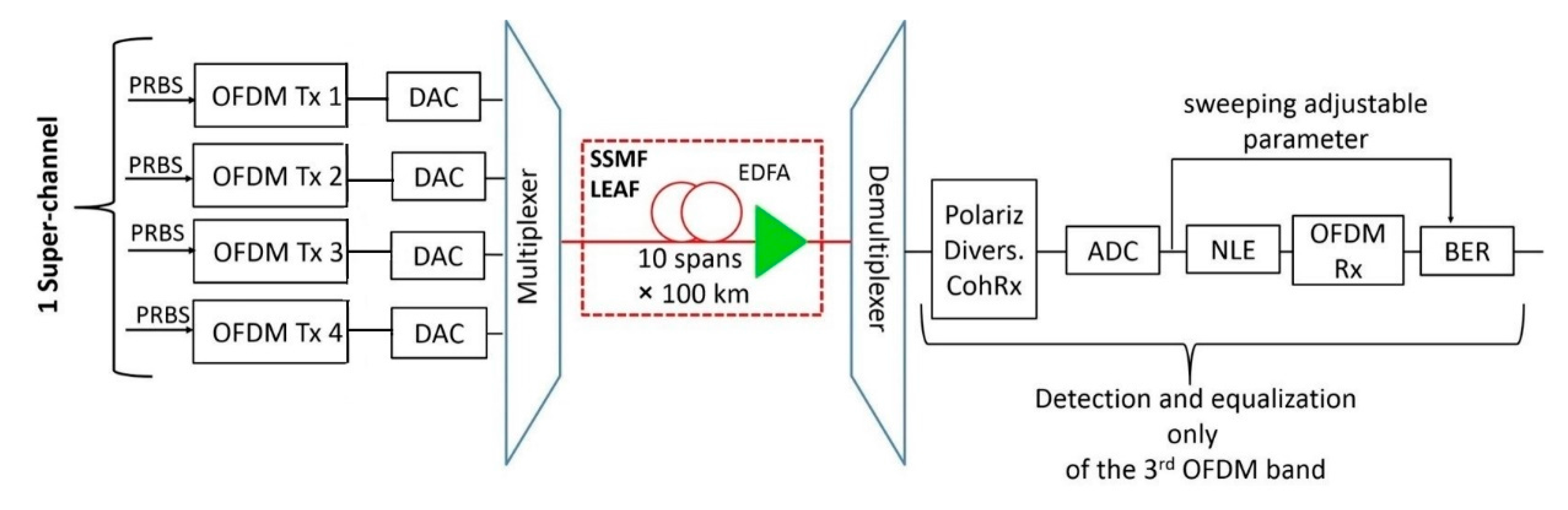
In this paper, we experimentally investigate the performance of the 3rd-order IVSTF-NLE in a WDM experimental using a 400 Gb/s, DP, 16QAM, OFDM super-channel at the center of a WDM comb, after propagating through 10 × 100 km of an SSMF [
16]. In addition, its performance is compared with the conventional DBP-SSF method with multiple steps per span [
9]. Then, we extend the comparison study, via Monte Carlo simulations, by replacing the SSMF with a large effective area fiber (LEAF) to test the robustness of the 3rd-order IVSTF-NLE against the multi-span DBP-SSF NLE in the presence of stronger nonlinear effects. We observe that, in the presence of strong nonlinear effects, the 3rd-order IVSTF-NLE performs similarly to the almost twice more complex DBP-SSF with two-steps-per-span, whereas the eight steps-per-span DBP-SSFR is only slightly better. Nonetheless, the later algorithm is very demanding, in terms of real multiplications, as we estimate in the present study.
The rest of the paper is organized as follows: In
Section 2 and
Section 3, the experimental and the simulation setups are described, respectively. In
Section 4, we present and discuss the experimental and simulation results. In addition, we estimate the computational complexity of the NLEs in terms of the number of real multiplications. Finally, the conclusions are summarized in
Section 5.
2. Experimental Section
The 3rd-order IVSTF-NLE used in this experimental study is based on the algorithm published in [
16]. For completeness and for the reader’s convenience, we summarize below the major schematics highlighting its operating principle, whereas the theoretical model is summarized in the
Appendix A.
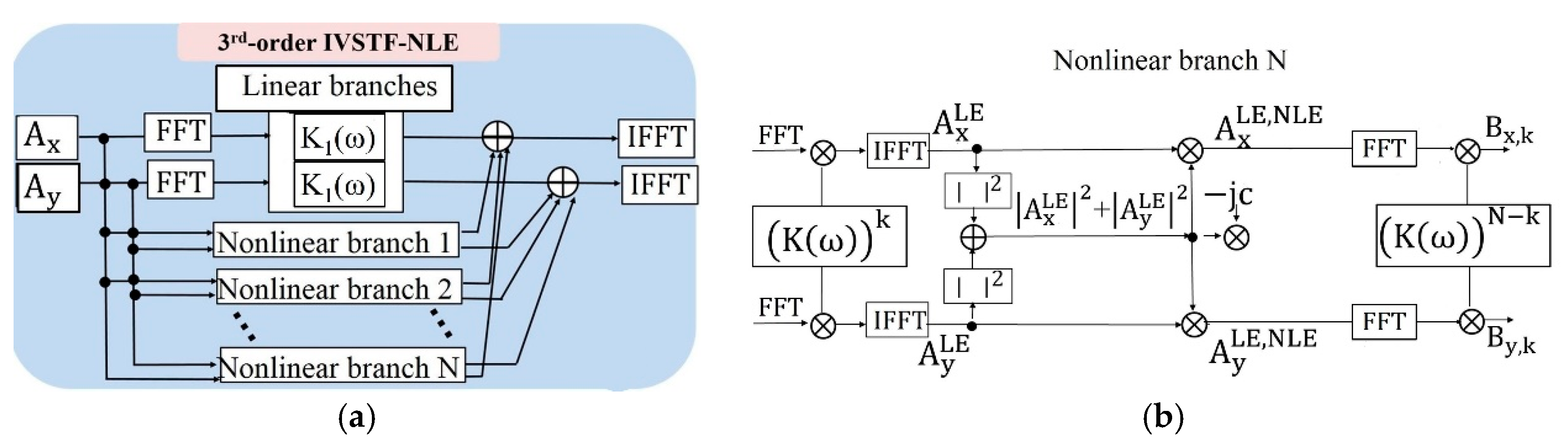
The block diagram of the 3rd-order IVSTF-NLE is shown in
Figure 1a. The equalization is performed in parallel. In the block diagram of
Figure 1a, the linear compensation is represented by the two upper arms and the nonlinear compensation by the
N nonlinear branches. The linear compensation comprises a single branch per polarization, accounting for the chromatic dispersion (CD) introduced by all the
N fiber spans, in the frequency domain. Each polarization tributary passes through a filter with transfer function
(see Expression (A5) in the
Appendix A). On the other hand, the nonlinear compensation is implemented in a span-by-span basis through
N separate branches, as described in (A6).
Figure 1b illustrates the operating principle of the
kth nonlinear branch, which is divided into three stages. The first stage performs CD compensation in the frequency domain, and it is realized through the filter
(see Expression (A7) in the
Appendix A). The second stage is the compensation of the intra-channel nonlinearities, in the time domain, implemented as described in (A8). The third and the last stage of each nonlinear branch is the compensation of the residual dispersion, in the frequency domain, through a filter with transfer function
(see Expression (A9) in the
Appendix A). More specifically, first, the received
x and
y polarization tributaries (i.e.,
and
) are linearly compensated in the frequency domain. Then, the linearly-compensated polarization tributaries are switched back in the time domain (i.e.,
and
) for the intra-channel nonlinearity equalization where each one of them is multiplied with the instantaneous power of
x and
y polarization (i.e.,
) scaled by the adjustable parameter
. The optimization of the latter is achieved by sweeping a range of values in the vicinity of its nominal value
, where
is the effective span length. Finally, the polarization tributaries
and
are switched again to the frequency domain, where the residual CD is compensated through a filter with transfer function
.
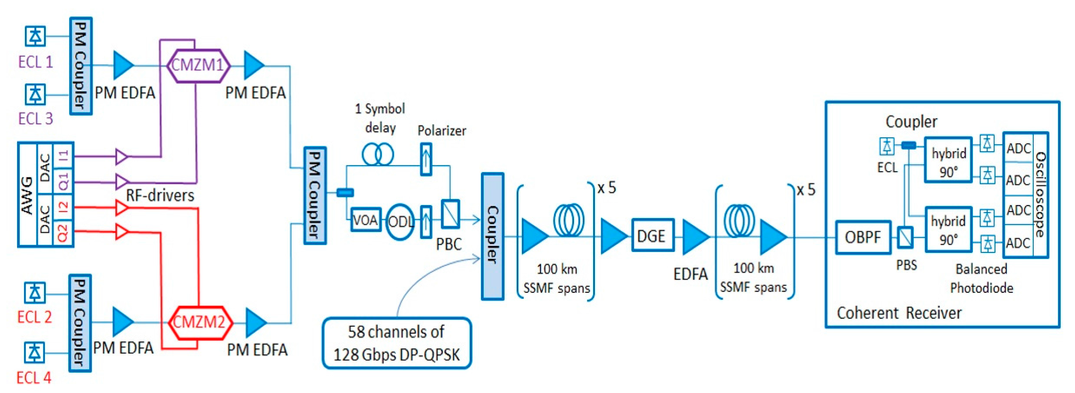
The experimental setup is depicted in
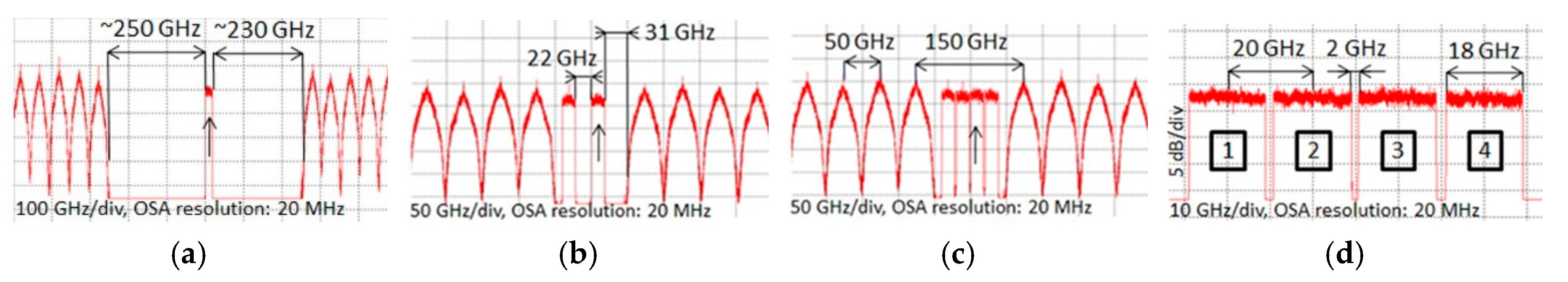
Figure 2. The configuration consists of a coherent, DP 16QAM OFDM super-channel in a 10 × 100 km transmission line carrying a net bit rate of 400 Gb/s. The OFDM super-channel consists of 4 bands. Thus, the net bit rate per band is equal to 100 Gb/s. By adding 20% soft-decision forward error correction (SD-FEC) overhead and 20% OFDM overhead, including the cyclic prefix (CP), as well as the training sequence (TS) and the pilot tones, then, the raw bit rate per band is 144 Gb/s. Each band occupies 18 GHz (
Figure 3d). A guard-band of 2 GHz is introduced to limit the crosstalk between adjacent bands. The total bandwidth of the super-channel is 78 GHz, corresponding to a net spectral efficiency of 5.13 b/s/Hz. The OFDM frame is generated by Matlab
® using a 1024-point fast Fourier transform (FFT)/inverse FFT (IFFT). There are 576 subcarriers, each carrying 16QAM. They are generated by a 15-GHz bandwidth Keysight
® arbitrary waveform generator (AWG) operating at 64 Gsamples/s. The in-phase and quadrature components of the coherent OFDM signal are electrically amplified using two linear RF driver amplifiers (SHF807), which feed a quadrature modulator (CMZM). The first CMZM generates the odd channels while the second generates the even channels, in order to totally decorrelate the data carried by adjacent channels. The odd and even combs are combined together using a 3-dB polarization maintaining (PM) coupler. The polarization multiplexing is realized by dividing the signal into two paths, putting a delay of one-OFDM-symbol-duration on one of the paths, switching it to the perpendicular polarization, and combining them together, as shown in
Figure 2. The one-OFDM-symbol-duration delay corresponds to 1152 samples (1024 FFT size samples and 128 CP samples). Then, the OFDM super-channel is combined with 58 wavelengths modulated at 100 Gb/s using DP-QPSK and spaced 50-GHz apart from each other. The transmission line is composed of 10 spans of 100 km of SSMF. A single-stage erbium doped fiber amplifiers (EDFAs), with 20 dB gain and ~4.5 dB noise figure, is applied at the end of each span and for all the 10 spans. At this point, we note that the linear and non-linear equalization schemes that are presented in this paper are not adaptive but feed forward schemes. Although they may require exact knowledge of the system’s parameters to operate, their operation is not affected by the amount of accumulated noise at the receiving end. On the other hand, their effectiveness in improving the system performance is affected by the noise added by the EDFA elements along the link and the nonlinear mixing between signal and noise. This additional non-linear noise effect cannot be treated by any equalization scheme at the receiver, but only with the use of distributed compensation methods, such as all optical regenerators or cascaded optical phase conjugation (OPC) elements [
24].
A dynamic gain equalizer (DGE) is introduced in the middle of the link to flatten the multiplex power after 10 × 100 km. At the end of the link, an optical bandpass filter (BPF) selects the OFDM band under measurement. This one is detected by a polarization- and phase-diversity coherent receiver using an external cavity laser (ECL) with 100 kHz linewidth as local oscillator (LO). The effective number of bits (ENoB) in the digital-to-analog converters (DACs) and in the analog-to-digital converters (ADCs) is approximately 5. We use 106 bits to evaluate the bit error rate (BER) by error counting.
We consider three scenarios to explore the physical limits of the NLEs performance: (a) a single-channel transmission of a single-band DP, 16QAM OFDM signal (
Figure 3a); (b) WDM transmission with a 2-band DP, 16QAM OFDM signal (
Figure 3b), and, finally (c) WDM transmission with a 4-band, DP, 16QAM OFDM super-channel at the center of the WDM comb (
Figure 3c).
The power spectra are recorded by a high-spectral-resolution (20 MHz) optical spectrum analyzer (OSA). The first scenario corresponds to a to a pseudo-single-channel transmission scenario in which the cross-phase modulation (XPM) and the four wave mixing (FWM) are considered practically negligible (
Figure 3a). In the second scenario, the inter-channel nonlinearities are increased (
Figure 3b). Finally, the third study case exacerbates the intra- and inter-channel nonlinearities (
Figure 3c). The guard-band spacing between the third OFDM band and its immediate left/right neighbors are 250/230 GHz, 22/31 GHz and 2/2 GHz for the study cases (a), (b) and (c), respectively.
For the detection of the OFDM band under study, we used a 50 GSa/s sampling rate real-time oscilloscope, followed by resampling at 32 GSa/s. The latter is the sampling frequency used by the NLEs. The off-line OFDM signal processing is thoroughly described in [
25]. In the coherent receiver, IVSTF-NLE and DBP-SSF equalizers are placed at the initial stages of the digital signal processing (DSP), where CD compensation is usually performed [
26]. The detected OFDM band has an aggregate symbol rate of 18 Gbaud. Thus, the NLEs operate with 1.8 SpS. In order to achieve this, we have applied down-sampling, in the frequency domain, right before the NLEs. After the NLEs, we apply one more down-sampling, again in the frequency domain, in order to achieve 1 SpS. Through trial and error, it was observed that further increase of the number of SpS provides just a marginal performance improvement adding unnecessarily computational load.
4. Results and Discussion
In the following, we present experimental and numerical results for the performance of the 3rd-order IVSTF-NLE and the DBP-SSF method, varying the number of steps per span. For brevity, we denote the different versions of the DBP-SSF NLEs as DBP-SSF
Nsteps, where
Nsteps is the number of steps per span. In both, experimental and simulation, studies we have only detected the 3rd-band of the central OFDM super-channel, since inner bands are more affected by inter-channel nonlinear impairments compared to the outer bands. To compare the performance of different NLEs, we use the
Q2-factor as a figure of merit, which is related to BER by
Q2 (dB) = 20log
10 [√2 erfc
−1 (2BER)] [
16]. We estimated the net
Q2-factor improvement (
) in dB which is obtained as follows: First, we estimated the maximum
Q2-factor value when only linear equalization is applied (max.
). Second, we applied both, linear and nonlinear, equalization and we evaluated the corresponding maximum
Q2-factor value (max.
). We define as
the net
Q2-factor improvement, thus, the higher the
, the better the performance of the NLE. For both, experimental and simulation, results four trials were conducted and then the average was calculated and recorded as the final value.
4.1. Experimental Results
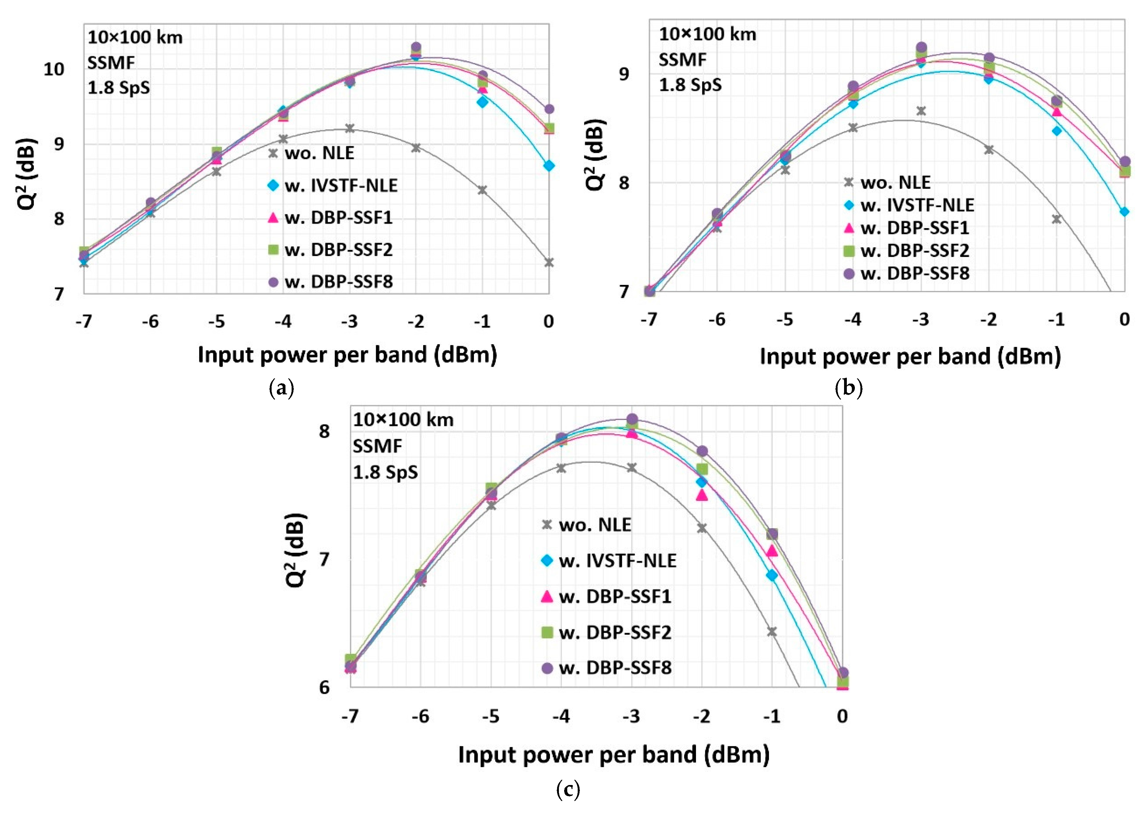
Figure 5a shows the maximum
Q2-factor as a function of the launch power after 10 × 100 km of SSMF for single-channel transmission with linear compensation only, as well as with IVSTF or DBP-SSF
1,2,8 NLEs (scenario described in
Figure 3a). The
Q2-factor improvement is ~1 dB (i.e., BER = 3.2 × 10
−3 with linear equalization only (wo. NLE) and BER = 9.9 × 10
−4 with linear and nonlinear equalization (w. NLE)) for all NLEs, which agrees with the published results for the single-channel, single-carrier system in [
16].
Figure 5b corresponds to a WDM coherent optical system with two OFDM bands at its center (scenario described in
Figure 3b). In this case, the
Q2-factor improvements are ~0.44 dB (i.e., BER = 5.3 × 10
−3 wo. NLE and BER = 3.6 × 10
−3 w. NLE) for the 3rd-order IVSTF-NLE, ~0.5 dB for the DBP-SSF
1 NLE, and ~0.6 dB (i.e., BER = 5.3 × 10
−3 wo. NLE and BER = 3.2 × 10
−3 w. NLE) for the DBP-SSF
2,8 NLEs. We observe that, in this scenario, the performance of the DBP-SSF method saturates at two steps per span.
Figure 5c shows representative plots of the
Q2-factor vs. input power per band for a central 4-band OFDM super-channel surrounded by WDM DP QPSK channels (scenario described in
Figure 3c). The measured
Q2-factor improvements are ~0.33 dB (i.e., BER = 7.5 × 10
−3 wo. NLE and BER = 5.8 × 10
−3 w. NLE) for the 3rd-order IVSTF-NLE, ~0.28 dB for the DBP-SSF
1 NLE, ~0.35 dB (i.e., BER = 7.5 × 10
−3 wo. NLE and BER = 5.7 × 10
−3 w. NLE) by the DBP-SSF
2 NLE and ~0.4 dB (i.e., BER = 7.5 × 10
−3 wo. NLE and BER = 5.5 × 10
−3 w. NLE) by DBP-SSF
8 NLE.
Summing up our observations from the experimental results, we note that all NLEs mitigate equally well the intra-channel nonlinear effects (
Figure 5a) but their performances degrade when the inter-channel nonlinear crosstalk is also considered (
Figure 5c). This modest performance improvement is mainly due to the detection and compensation of each OFDM band separately, leaving inter-channel nonlinearities uncompensated. We observe that the IVSTF-NLE is worse compared to DBP-SSF method for input powers per band higher than the optimum because as the input power per band increases, the nonlinear effects become stronger requiring more computational steps to achieve their compensation. In addition, we observe that the DBP-SSF method reaches its optimum performance at 8 steps per span. Nevertheless, the latter is only marginally more powerful compared to the DBP-SSF
2 NLE. Therefore, as the nonlinear phenomena become stronger, larger number of steps per span are required for the DBP-SSF method to reach its performance limit. On the contrary, the 3rd-order IVSTF-NLE, which operates with a single step per span, performs almost as good as the DBP-SSF
2 NLE, with the latter being twice more complex than the former. Finally, we emphasize that the primary focus of the experimental results is to compare and gain a better insight about the potential of each NLE in the presence of very strong nonlinear effects. Although the performance results of all NLEs is modest, especially in the worst-case scenario (see
Figure 5c), they are indicative of the fact that the 3rd-order IVSTF-NLE can compete with significantly lower computational effort the heavily iterative DBP-SSF with multi-steps per span.
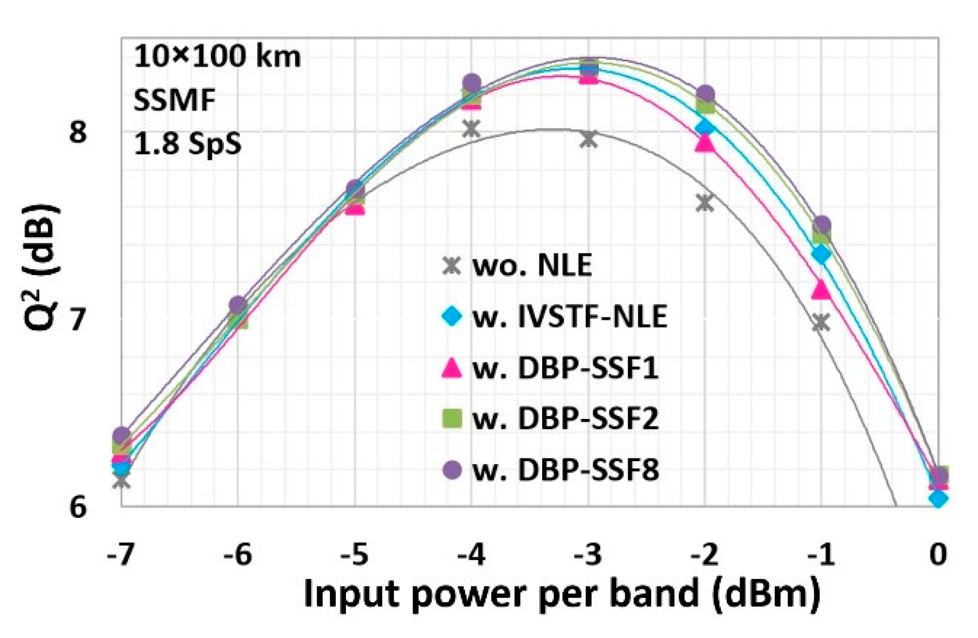
4.2. Simulation Results
The first step in the simulation study was to validate the model that we implemented. For this matter, we performed
Q2-factor evaluation as a function of the input power per band after propagation through 10 × 100 km of an SSMF, using 1.8 SpS for the equalization process. All NLEs were optimized, as we did for the experimental study, through their adjustable parameters [
9,
16]. The simulation results are shown in
Figure 6. The measured
Q2-factor improvements, compared to linear equalization, are ~0.32 dB (i.e., BER = 5.9 × 10
−3 wo. NLE and BER = 4.6 × 10
−3 w. NLE) for the 3rd-order IVSTF-NLE, ~0.3 dB (i.e., BER = 5.9 × 10
−3 wo. NLE and BER = 4.6 × 10
−3 w. NLE) for the DBP-SSF
1 NLE, and ~0.35 dB (i.e., BER =5.9 × 10
−3 wo. NLE and BER = 4.5 × 10
−3 w. NLE) for the DBP-SSF
2,8 NLEs. There is a very good agreement with the experimental results represented in
Figure 5c. Thus, our model is a fair representation of the experimental setup.
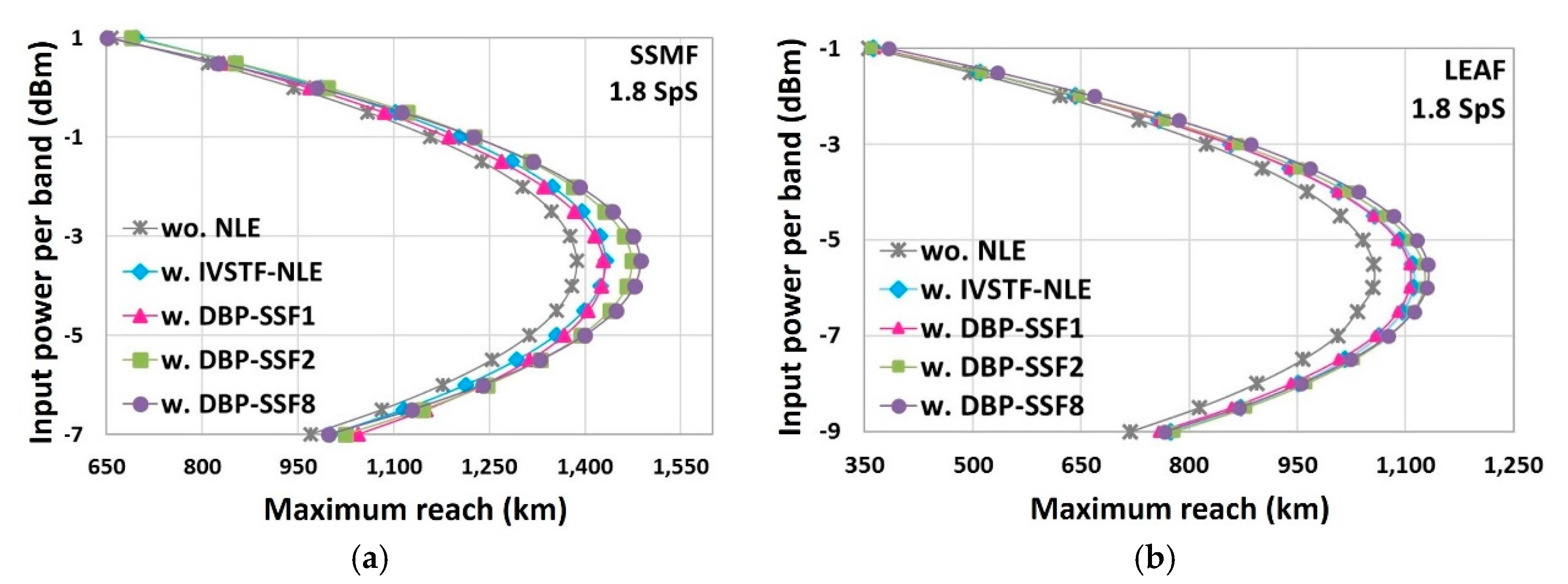
Next, we compare the maximum reach versus input power per band, with and without the NLEs, after signal transmission through an SSMF and a LEAF.
Figure 7a shows that the maximum reach is achieved for input power per band equal to −3 dBm in SSMF, in all cases. At the FEC limit (i.e., BER = 2 × 10
−2 or
Q2 = 6.25 dB), the maximum reach is 1400 km with linear equalization only. After nonlinear compensation, the maximum reach was extended ~3% for the 3rd-order IVSTF-NLE, ~3% for the DBP-SSF
1 NLE, ~4.6% for the DBP-SSF
2 NLE and ~7% for the DBP-SSF
8 NLE, with respect to linear equalization. We observe that the DBP-SSF method slightly outperforms the 3rd-order IVSTF-NLE, especially if the number of steps per span increases.
Then, we replace the SSMF with LEAF to investigate how the maximum reach is affected when the nonlinear impairments become stronger. In
Figure 7b, the maximum reach without NLE is 1100 km in LEAF, which is 300 km shorter compared to SSMF. The maximum reach is extended by ~6.3% for the 3rd-order IVSTF-NLE, ~5.4% for the DBP-SSF
1 NLE, ~6.3% for the DBP-SSF
2 NLE, and ~7.3% for the DBP-SSF
8 NLE compared to linear case. The DBP-SSF method with eight steps per span is once more the NLE with the best performance, compared to all the aforementioned NLEs, but at the vast expense of computational complexity, as shown in the following sub-section.
The modest reach extensions provided by the NLEs provide valuable information about their physical limits while the nonlinearities increase gradually. Especially from
Figure 7b, it is observed that even though the nonlinear effects have been further increased, due to the replacement of the SSMF with a LEAF, the performance of the single-step-step-span 3rd-order IVSTF-NLE has been improved (i.e., from ~3% in SSMF increased to ~6.3% in LEAF). On the contrary, the DBP-SSF method needs eight-steps-per-span in order to provide the maximum reach extension (i.e., ~7% in both, SSMF and LEAF, cases). Thus, in LEAF case, the performance of the 3rd-order IVSTF-NLE differs only slightly compared to the performance of DBP-SSF
8 NLE while the former is almost eight times less complex.
4.3. Evaluation of Computational Complexity
The computational complexity is one of the criteria used to decide whether a specific NLE is suitable for real-time implementation. Therefore, in this subsection, we evaluate the computational complexity of the various nonlinear compensation methods, in terms of the number of real multiplications per sample per polarization. In addition, we compute the maximum Q2-factor provided by the various NLEs as a function of complexity, after transmission through SSMF and LEAF.
First, we estimate the computational complexity of the 3rd-order IVSTF-NLE in terms of real multiplications per sample per polarization following the method of [
16]. However, in our calculations, and modeling, we used the same FFT block size (
NFFT) for both the linear and the nonlinear branches, while in [
16] each of the nonlinear branches operate with
NFFT/2. We decided to use the same
NFFT in both, the linear and the nonlinear, branches because it was observed, through trial and error, that only then the 3rd-order IVSTF-NLE exhibits its best performance in the worst case scenario (see
Figure 3c) and after 1000 km of SSMF using only 1.8 SpS. We consider a radix-2 implementation of FFT. In this case, the number of real multiplications for every FFT/IFFT is equal to 2log
2NFFT [
16]. Therefore, the FFT and the IFFT at the input and at the output of the IVSTF-NLE, respectively, are realized with 4log
2NFFT real multiplications [
16]. The linear branch of the IVSTF-NLE, as depicted in
Figure 1a, operates with 4 real multiplications.
At each nonlinear branch (
Figure 1b), CD compensation is performed with 4 real multiplications per sample, in the frequency domain. Next, an IFFT requires 2log
2NFFT real multiplications in the time domain. Then, 5 real multiplications per sample per polarization are required for multiplying the total power of
x and
y polarizations with
jc (i.e.,
CIVSTF). The latter multiplication is common between the two polarizations, thus, only 2.5 multiplications are required per sample per polarization. An FFT follows, with 2log
2NFFT real multiplications, for the compensation of the residual CD in the frequency domain, adding 4 more real multiplications. Totally, 4 + 4log
2NFFT +
Nspans × (4log
2NFFT + 10.5) real multiplications per sample per polarization are needed for the operation of the 3rd-order IVSTF-NLE. For the DBP-SSF method, the required number of real multiplications per polarization per sample is
Nsteps ×
Nspans × (4log
2NFFT + 10.5) [
16].
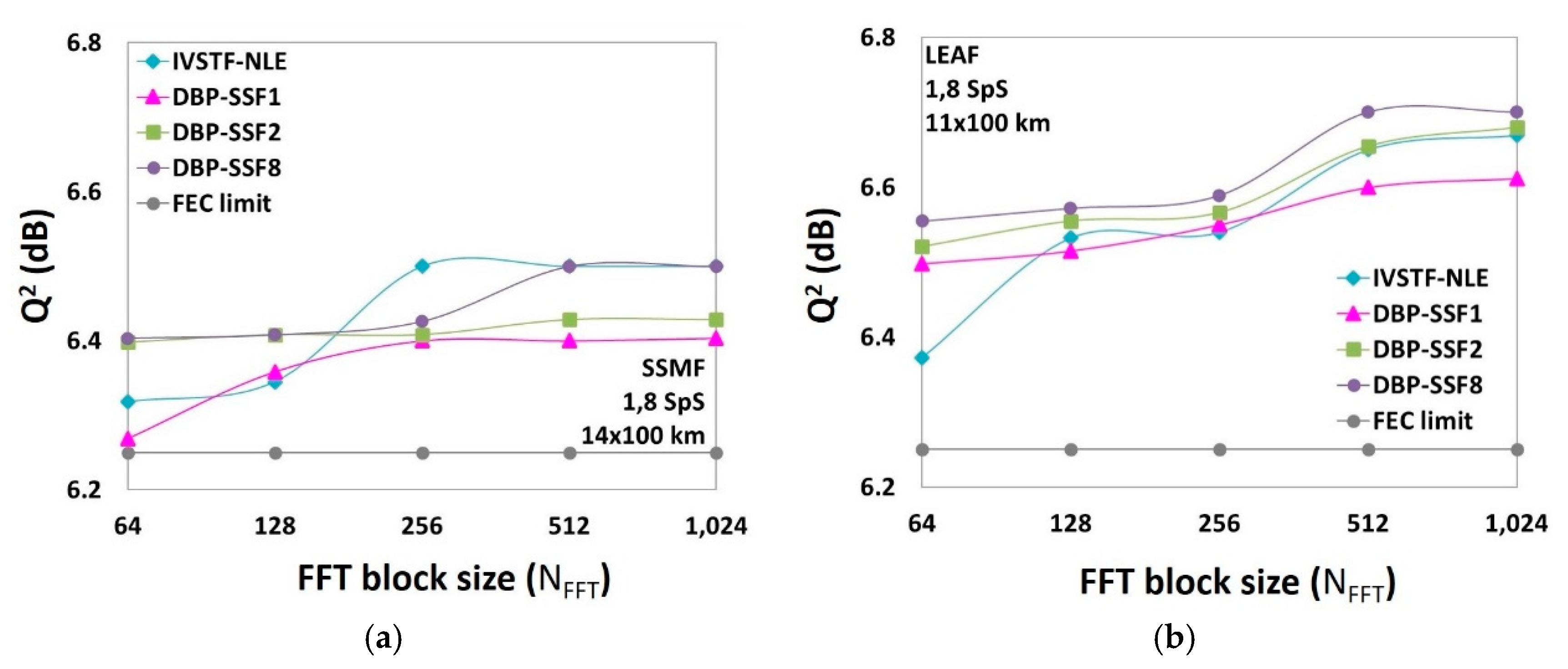
From the computational complexity analysis, it is obvious that the lower the NFFT, the lower the computational complexity per block. At this point, the key question is if there is an optimum NFFT, at which the performance limit of each NLE can be reached with a minimum computational complexity per block. To answer this question, we applied, right before each NLE, the method of overlap and save (OS) to divide the received, uncompensated signal into small FFT blocks. After the full compensation of each block (i.e., linear and nonlinear), we aggregated them back together, at the output of each NLE, to form the output signal. Then, we measured the Q2-factor as a function of the NFFT, after 14 × 100 km of SSMF, at the optimum input power per band (i.e., −3 dBm). We chose this transmission reach because it corresponds to the FEC limit without nonlinear compensation (i.e., Q2 = 6.25 dB). Following a similar rationale, we repeated the simulation runs after 11 × 100 km of LEAF, at optimum input power per band equal to −6 dBm.
Figure 8a,b show the results for the SSMF and LEAF study, respectively. In both cases, all NLEs reach their performance limit, at a certain
NFFT.
Table 1 and
Table 2 show the
Q2-factor improvement, with respect to the FEC limit, provided by each NLE, at the optimum
NFFT as well as the number of real multiplications required per sample per polarization for these improvements. After SSMF transmission (
Table 1), we observe that the 3rd-order IVSTF-NLE is as good as the DBP-SSF
8 NLE but with the latter being almost eight times more complex. After LEAF transmission (
Table 2), we observe that, in the presence of stronger nonlinear effects, the 3rd-order IVSTF-NLE is as good as the DBP-SSF
2 NLE with the latter requiring ~2 times more real multiplications, compared to the former. Finally, the DBP-SSF
8 NLE is only marginally better compared to the IVSTF-NLE.
The estimations, summarized in
Table 1 and
Table 2, validate what it was already observed in the experimental and the simulation results, and this is the fact that the performance of the DBP-SSF method saturates with eight-steps-per-span, whereas the improvement it provides is comparable to the improvement provided by the significantly less complex 3rd-order IVSTF-NLE. Although we understand that the differences from the performances of DBP-SSF
1,2 NLEs might sound modest, we still draw useful conclusions considering the physical limits of the NLEs in the presence of increased nonlinearities.
5. Conclusions
We compare, experimentally, the performance of a 3rd-order IVSTF-NLE and the DBP-SSF method, with various numbers of steps per span, in a coherent optical WDM system, with a central 400 Gb/s 4-band, DP-16QAM OFDM super-channel exacerbating the intra- and inter-channel nonlinearities. Then, we extend the study numerically by estimating the maximum transmission reach, provided by the NLEs under study, with respect to the FEC limit after transmission in a LEAF. Both, the experimental and the simulation, results reveal that the performance of the single-step-per-span 3rd-order IVSTF-NLE can compete the well-known DBP-SSF method. The latter requires eight-steps-per-span in order to reach its optimum performance which, however, is comparable with the performance with the almost eight times less complex 3rd-order IVSTF-NLE. Although the differences in the performance of the DBP-SSF1,2 NLEs, compared to the DBP-SSF8 NLE and the 3rd-order IVSTF-NLE, are only marginal, they are still indicative of the robustness of each and every NLE in the presence of exacerbated nonlinear effects. Thus, the 3rd-order IVSTF-NLE could be a reasonable choice for compensating nonlinear impairments with lower computational complexity and, by extension, lower cost.
More generally, our study confirms that digital nonlinear equalization is especially efficient to mitigate intra-channel nonlinear effects and less convenient when also inter-channel nonlinearities are involved. However, with the increase of data rate carried by the sub-channels constituting the super-channel (supported by the improvement of bandwidth/resolution of DACs/ADCs), digital nonlinear equalization could know a renewed interest because, at high bit/symbol rate per sub-channel, intra-channel nonlinearities are predominant.

 ,
, 


