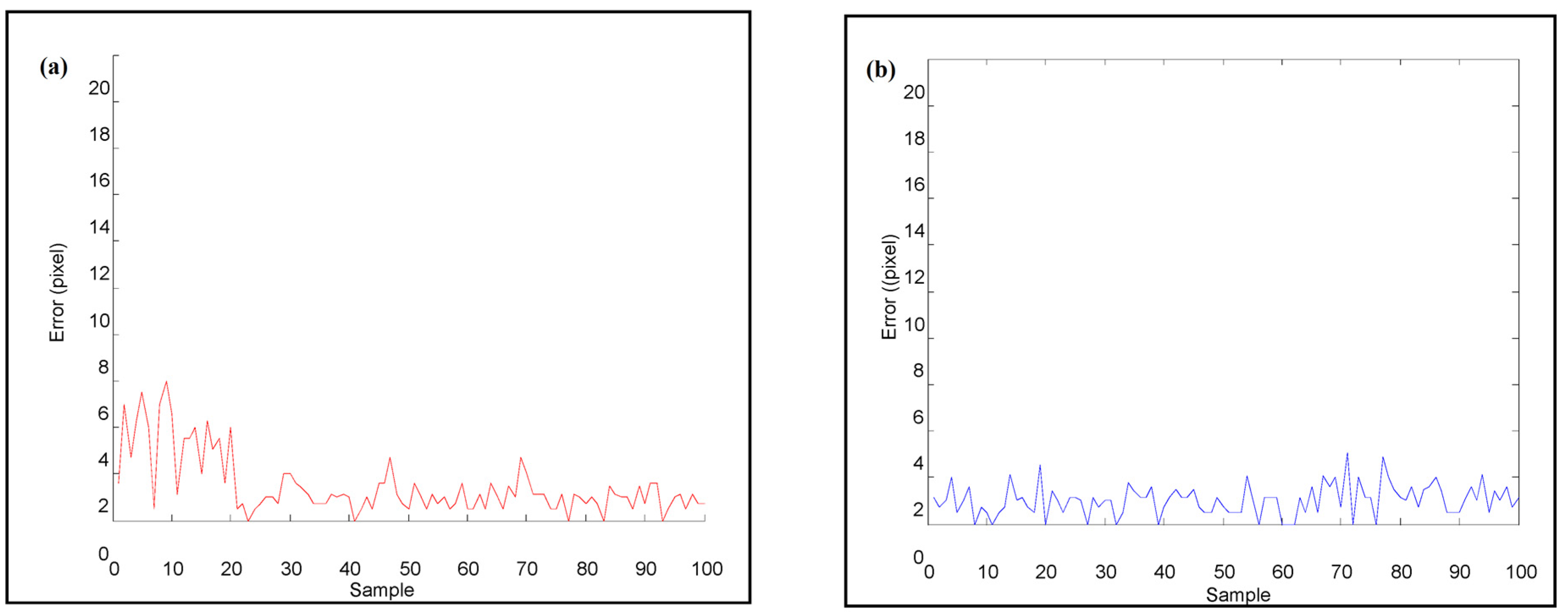
Article

Design of an Image-Servo Mask Alignment System Using Dual CCDs with an XXY Stage

1
Graduate Institute of Automation Technology, National Taipei University of Technology, Taipei 10608, Taiwan
2
Department of Mechanical and Automation Engineering, Da-Yeh University, Changhua 51591, Taiwan
*
Author to whom correspondence should be addressed.
Appl. Sci. 2016, 6(2), 42; https://doi.org/10.3390/app6020042
Submission received: 9 October 2015 / Revised: 8 January 2016 / Accepted: 21 January 2016 / Published: 2 February 2016

Abstract

:
Mask alignment of photolithography technology is used in many applications, such as micro electro mechanical systems’ semiconductor process, printed circuits board, and flat panel display. As the dimensions of the product are getting smaller and smaller, the automatic mask alignment of photolithography is becoming more and more important. The traditional stacked XY-Θz stage is heavy and it has cumulative flatness errors due to its stacked assembly mechanism. The XXY stage has smaller cumulative error due to its coplanar design and it can move faster than the traditional XY-Θz stage. However, the relationship between the XXY stage’s movement and the commands of the three motors is difficult to compute, because the movements of the three motors on the same plane are coupling. Therefore, an artificial neural network is studied to establish a nonlinear mapping from the desired position and orientation of the stage to three motors’ commands. Further, this paper proposes an image-servo automatic mask alignment system, which consists of a coplanar XXY stage, dual GIGA-E CCDs with lens and a programmable automatic controller (PAC). Before preforming the compensation, a self-developed visual-servo provides the positioning information which is obtained from the image processing and pattern recognition according to the specified fiducial marks. To obtain better precision, two methods including the center of gravity method and the generalize Hough Transformation are studied to correct the shift positioning error.

Graphical Abstract

1. Introduction

For most manual alignment systems, operators easily become fatigued after a long working period using the optical inspection system. Human errors are the source of lack of control and instability in manual assembling. Therefore, manual alignment accuracy cannot be guaranteed due to the operation variations of different workers at different times. To increase assembling accuracy and alignment stability, automatic image-servo systems have been proposed [1,2,3,4,5]. Sanderson and Weiss proposed an image-based visual servo control to study the automatic assembling task using the relational graph error signals [1]. Kim et al. used two-stage alignment techniques to find the fiducial mark and used two CCDs to check the wafer bonding alignment [2]. Later, Kim et al. studied a neural network method for quick wafer alignment to reduce complexity of motion analysis [3].
To achieve mask alignment tasks rapidly and accurately using automatic optical inspection (AOI) technologies, there are three key points which affect the cycle time and positioning accuracy. The three issues are (1) the fiducial mark design; (2) image processing and pattern recognition; and (3) image-servo motion control. For the design of fiducial mark, cross and circular marks are usually used in alignment applications, such as high-density laser-fiber module packaging tasks, semiconductor wafer alignment systems, and automatic alignment systems for I-line stepper. Cohen et al. explored a novel method for packaging a laser-fiber module with a passive method based on registration principles of photolithography; they proposed the alignment method using the fiducial marks of crosses [6]. Tichem and Cohen studied a sub-micro registration between circularly symmetric fiducial marks to find their centroids by the second-derivative zero-crossing method [7]. Fernandez and Amat were devoted to obtaining a proper fiducial mark design that optimizes the reliability of robotic manipulation; they studied several fiducial mark shapes via ophthalmic lenses in alignment processes [8].
The general alignment system contains one, two or more charge coupled device (CCD) cameras to guide a high-precision positioning stage. Kuo et al. presented a precision alignment system integrated with machine vision, consisting of a stacked XY positioning stage driven by piezoelectric ceramic motors [9]. The above research used a circular fiducial mark as the alignment marks captured by a CCD camera and the positional error was below 60 nm. Lin et al. presented a micro-assembly system based on vision-servo guidance system, which incorporates two vision sensors to guide the XYθz stage to perform the coarse positioning task and the fine positioning task. The circular fiducial mark is used as the coarse positioning alignment and the cross fiducial mark is used for the fine alignment task. The designed image recognition system is integrated into the micro-assembling system with image-servo to achieve the precise assembling task automatically, and the repeatable precision was better than 10 μm [10]. Lee et al. presented a real time critical dimension measurement of pattern on TFT-LCD and the searching time for XYθz was about 12 ms with repeatability of less than 30 nm [11]. Huang and Lin used a cross symbol as the fiducial mark of their proposed vision-servo alignment system and the alignment error was less than 1 μm [12]. However, their angular alignment accuracy was worse than two CCD cameras’ alignment due to low angular resolution using one CCD camera.
The alignment using the stacked XYθz stage usually causes cumulative errors, such as parallelism, orthogonal errors between axles and flatness error. To address the above errors, the coplanar XYθz stages have been proposed and they show good positioning accuracy in many studies [9,10]. Lee and Liu presented an image alignment system with visual servo control by using a special design coplanar XXY stage, and each alignment motion was less than 1 s with accuracy of ±1 μm and ±5 arc sec [11]. Yang et al. proposed an automatic locating and image-servo alignment design with four CCDs integrated with the coplanar XXY stage for an automatic laminating machine for the touch panel [4]. Lin et al. designed an optical alignment system using the coplanar XXY stage integrated with dual CCDs. Although, Lin et al. used a neural network method to increase the accuracy of their image-servo system [5]. However, the time taken for image pattern matching and image processing should be improved for real-world implementation.
This study focuses on two key issues of the image-servo mask alignment system using the XXY stage. The first one is to deal with the nonlinear motion planning of the XXY stage due to coupling effects. Although the coplanar XXY stage has some advantages such as smaller cumulative errors and quicker response than the stacked XYθz stage, motion planning of the XXY stage is difficult to compute as the X1-, X2- and Y-axes’ movements are coupling and its kinematic relationship is nonlinear. Therefore, an ANN-based motion planning is proposed in this paper to solve this problem. The second one is to solve pattern recognition of the alignment marks as the positioning marks overlap. Because overlapped marks make it difficult to recognize each mark using the center of gravity method, another image processing and pattern recognition method robust to overlapping is needed to improve the accuracy of mask alignment. The generalized Hough Transform (GHT) is studied to find the dual positioning marks in this paper.
The rest of this paper is organized as follows: in Section 2, the nonlinear kinematic relationship of the XXY stage is discussed at first and then the supervised learning ANN and the back-propagation neural network (BPNN) is investigated to establish the relationship between the motor command’s and the actual position in the global frame. In Section 3, the positioning fiducial mark as well as the image-servo alignment, the image processing and pattern matching methods to extract the positions of the fiducial mark. Some alignment problems are discussed and a solution is proposed. In Section 4, after obtaining the positon of the two sets of the fiducial mark images, the position compensation and the angular orientation of the alignment part on the XXY stage can be calculated. Then, the compensation command for the XXY stage can be obtained according to the D-H transformation and they can then be fed back to the image-servo loop to achieve precision alignment tasks. In Section 5 we conclude with a summary of our contributions.

2. Motion Planning of XXY Stage Using the ANN

Lithography is a cost-efficient and widely used technology for the manufacturing of microstructures or MEMS on wafers. The photosensitive material is placed in a developer solution after selective exposure to a light source, and lithography typically involves the transfer of a pattern to the photosensitive material by a mask to determine which will be etched away. A mask aligner is the machine which actually transfers the pattern onto the wafer and the mask has the desired pattern on it. A high intensity ultraviolet light is placed over the mask. The light only transmits through the openings in the pattern allowing the pattern to be burned into the photoresist on the wafer. In conventional mask aligners, the geometry of the effective light source which corresponds to the angular spectrum of illumination cannot be changed. Moreover, manual alignment systems are unreliable and time-consuming.
To improve the reliability of alignment task, an automatic image-servo alignment system (AISAS) is studied. The system consists of the upper mask apparatus, which is used to carry the upper mask, the lower coplanar XXY stage (CHIUAN YAN Ltd., Changhua, Taiwan), which is applied to carry the lower part to align the upper one by the image-servo control, and two distributed overhead GIGA Ethernet CCD cameras equipped with lenses, which are mounted to the top of the system individually as the image-servo sensors for positioning. Figure 1 describes the flow chart of the proposed image-servo alignment system and the details of each subsystem are discussed in the following sections.
Figure 1. Block-diagram for the proposed automated image-servo alignment system.
Applsci 06 00042 g001
The traditional XY-Θz stage is using the stacked mechanism (as shown in Figure 2a), which consists of an X-axis translation stage, a Y-axis translation stage and a Z-axis rotational stage. The controller design for the XY-Θz stage is easy, because each axis movement is independent. However, the XY-Θz stage has cumulative flatness errors due to stacked assembly and the stage’s size is large. Recently, a coplanar XXY stage is developed, because its coplanar design has smaller cumulative error and it can move faster than the traditional XY-Θz stage. Figure 2b shows the structure of the coplanar XXY stage, which is driven by three stepping motors, which are denoted as X1-axis motor, X2-axis motor and Y-axis motor [11]. The working stage is supported by four sub-stages; each sub-stage consists of X-translation, Y-translation and θz-rotation stages. Therefore, the motion of the XXY stage has three degrees of freedom (DOF), which are two translations of X-axis and Y-axis with one rotation of θz-axis.
Figure 2. (a) Traditional XY-Θz stage [13]; (b) Coplanar XXY stage [14].
Applsci 06 00042 g002

2.1. Motion Planning of XXY Stage

In this study, the coplanar XXY stage is controlled by a PC+PLC-based architecture. After capturing the positioning mark in the image space, the image processing and pattern matching methods are studied and discussed to extract the positions of the fiducial mark, such as (1) pattern matching; (2) Sobel edge finding; (3) morphology processing and (4) Hough transform. After obtaining the positon of the two sets of the fiducial mark images, the relationship between the image coordinate and the actual coordinate in Cartesian space should be established. However, the relationship between the XXY stage’s movement and the commands of the three motors is difficult to compute, because the movements of the three motors on the same plane are coupling. Therefore, an artificial neural network is studied to establish a nonlinear mapping from the desired position and orientation of the stage to three motors’ commands.
Without considering the rotational movement of θz, the relationship between the XXY stage’s displacement ( δ x , δ y ) and the stepper motors’ command is described as follows.
[ d x 1 d x 2 d y ] = R m l p [ 1 0 1 0 0 1 ] [ δ x δ y ]
where Rm is the motor resolution (unit: pulse/rev); lp is the lead of the ball-screw (unit: mm/rev); dx1, dx2 and dy are the commands for the X1-axis, X2-axis and Y-axis motors (unit: pulse). To make δθ = 0, the commands of the X1-motor and the X2-motor should be the same. However, considering the rotational movement of θz, because the rotational center of the XXY stage is not fixed as the stacked XY-Θz stage, the kinematic relationship is very complicated. The kinematic of the coplanar XXY stage can be formulated as follows [11].
[ d x 1 d x 2 d y ] = [ R m / l p 0 k a R m / l p R m / l p 0 k b R m / l p 0 R m / l p k c R m / l p ] [ δ x δ y δ θ ]
where δ x and δ y is the desired translation displacement of the stage and δ θ is the desired angular displacement of the stage; [dx1 dx2 dy]T is the motors’ commands (unit: pulse); ka, kb and kc are related to the distance between the XXY stage center and the working stage center. The relationship between [dx1 dx2 dy]T and [ δ x δ y δ θ ]T is complicated and nonlinear.

2.2. Experimental Results Using Linear Approximation Method

Before discussing the proposed ANN based motion planning, the linear relationship can be derived at first. In the study, the motor resolution Rm = 2000 (unit: pulse/rev) and the lead of the ball-screw lp = 2 mm = 2000 μm. Therefore, the minimum motion resolution is 1 μm for 1 pulse command of the motor. To obtain the relationship between the vision system and the actual displacement, two specified case studies are designed as follows.

Case I. Single-direction movement of XXY stage 

From Equation (1), using the same command for X1-axis and X2-axis motors makes the stage move in an X-axis direction. However, using the command for Y-axis motor can only make the stage move in a Y-axis direction. According the specified experiments, Table 1 and Table 2 show the actual results for the command and the positioning mark’s displacement in the vision space. From the experimental results, the ratio of vision displacement to the stage displacement (motor command) can be obtained by the average method. To compensate the positioning error by observing the positioning mark in the vision space, the following relationship can be obtained. As the motor driver’s command is 5.74 pulse (the actual displacement is about 5.74 μm), the part in the vision space will move a displacement of 1 pixel. In addition, there exists the positioning error in the actual implementation, because the motor driver can only accept the integer pulse command. Therefore, the ratio of the pulse command to the vision displacement, 5.74 μm/pixel, can be used for the image-servo control. [15]
Table 1. Movement experiment for X1-axis and X2-axis with the same command.
Command (pulse)Displacement in the Vision Space (pixel)
X1 MotorX2 MotorY Motor
200200034
400400069
6006000104
8008000139
100010000174
Table 2. Movement experiment for Y-axis.
Command (pulse)Displacement in the Vision Space (pixel)
X1 MotorX2 motorY Motor
0020033
0040070
00600103
00800138
001000175

Case II. Multiple-direction movement of XXY stage with rotation 

As mentioned in the above, the relationship between [dx1 dx2 dy]T and [ δ x δ y δ θ ]T is complicated and nonlinear, because the movement between X1-axis, X2-axis and Y-axis is coupling. Let the X1-axis motor be actuated but the X2-axis motor is fixed, Figure 3 describes the movement of the XXY stage. Figure 3 shows that the XXY stage rotates and the center of the stage moves at the same time. This means that the rotational command using the single X1-axis movement affects the stage’s positioning in the X-axis and Y-axis. Table 3 shows the experimental results of the two positioning mark in the vision space for the specified X1-axis command. Based on the experimental results, Table 4 shows the actual rotational and translational displacement obtained based on the kinematic relationship (which will be discussed in Section 4). To find the compensation value for the X-axis and Y-axis displacement as the rotational command is given to the X1-axis, the experimental results are used to compute the average ratio of the rotational displacement (degree) to the motor command (pulse) as shown in Table 5; the nonlinear relationship between [dx1 dx2 dy]T and [ δ x δ y δ θ ]T can be found in the fourth column of Table 5. Table 5 shows that the same pulse commands are applied to the motor driver in each interval, but the average value for δ θ / dx1 and the shifting displacement δx/dx1, δ y / d x 1 are different. To solve this problem, an artificial neural-network (ANN) is proposed to establish this mapping in the next section.
Based on the above experimental results, a linear approximated method is proposed and discussed for the relationship between [dx1 dx2 dy]T and [ δ x δ y δ θ ]T as follows. To obtain the motor’s command [dx1 dx2 dy]T for a displacement demand of [ δ x δ y δ θ ]T. First, the input for X1-motor’s command of δ θ can be obtained as follows.
C x 1 ( δ θ ) = δ θ × Δ θ   ( pulse )
where ∆θ = d x 1 / δ θ = 1/0.000372 = 2688.17 (pulse/deg) is the average value obtained from Table 5.
However, the rotational command Cx1( δ θ ) causes the stage to undergo a shifting displacement as follows.
S x ( δ θ ) = C x 1 ( δ θ ) × Δ x S y ( δ θ ) = C x 1 ( δ θ ) × Δ y
where ∆x = 0.503779, ∆y = −0.35501 (μm) is the average value obtained from Table 5.
Therefore, the motors’ command for the displacement of [ δ x δ y δ θ ]T can be formulated as follows.
d x 1 = δ x S x ( δ θ ) + C x 1 ( δ θ ) d x 2 = δ x S x ( δ θ ) d y = δ y S y ( δ θ )
where Cx1( δ θ ) is the rotational command and the purpose of subtracting Sx( δ θ ) and Sy( δ θ ) is to compensate the shifting displacement due to the rotational command. This formulation is the proposed linear approximated method; however, the actual rotation relationship is nonlinear from the observation of Table 5. To compensate the nonlinear effect, an artificial neural-network (ANN) is proposed to establish this nonlinear mapping in the next section.
Figure 3. Rotational movement of X1-motor with the shifting displacement.
Applsci 06 00042 g003
Table 3. Movement experiment for only X1-axis actuation.
Command (pulse)Displacement in the Vision Space (pixel)
X1 MotorX2 MotorY MotorX1Y1X2Y2
0200030219−23
0400059437−46
0600089655−69
08000121875−86
010000153994−120
Table 4. Rotational and translation movement for only X1-axis actuation.
Command (pulse)Displacement in the Global Space
X1 MotorX2 MotorY Motorδθ (degree)δx (μm)δy (μm)
020000.07102.7−75.3
040000.14199.7−150.5
060000.22296.4−220.6
080000.30404.5−296.5
0100000.39506.5−373.3
Table 5. Relationship between displacement and the X1-motor’s actuation.
Command (pulse)Displacement/Pulse in the Global Space
X1X2Yδθ/pulse (degree/pulse)δx/pulse (μm/pulse)δy/pulse (μm/pulse)
00 20000.000350.514−0.377
0200 40000.000350.485−0.376
0400 60000.000400.484−0.351
0600 80000.000400.541−0.380
0800 100000.000450.510−0.384

2.3. Motion Planning Using ANN

An artificial neural network (ANN) is invented based on the operation of biological neural networks, and it is defined as a collection of parallel processors connected in the form of a network such that the structure provides the nonlinear mapping between the input and output [16]. Recently, neural network techniques are applied to a complex control problem in the automotive industry and robotic motion planning. A sensor based navigation scheme which makes use of a global representation of the environment by means of a self-organizing network is presented in [3]. The aim of the application of the mobile robot for a motion planning problem is to obtain a collision-free path among moving obstacles with dynamic constraints to limit robot motions. Based on the idea of the ANN based motion planning in [16], this study investigates the use of the ANN to achieve nonlinear mapping between the image coordinates and the global coordinates for an image-servo problem. For training the ANN models, there are three types of algorithms, such as supervised learning algorithm, unsupervised learning algorithm, and associative memory learning algorithm. This study is suitable for using the supervised learning ANN, and the back-propagation neural network (BPNN) is investigated to establish the relationship between the motor command’s and the actual position in the global frame.
The main objective is to find a suitable mapping between the desired movement [ δ x δ y δ θ ]T and the necessary motor command [dx1 dx2 dy]T. The used ANN is the multilayer perceptron and the structure of the neural network, which contains four layers consisting of input, output and two hidden layers as shown in Figure 4. The layers are connected by synaptic weights and the learning operation is realized by a backpropagation (BP) algorithm based on the error-correction principle. The input-output relationship is described as follows.
Y j = f ( i w i j X i θ j )
where Xi is the i-th input, Yj is the j-th output, wij is the weight from the jth hidden neuron to the kth output neuron and θj is the threshold value. The activation function f(·) reflects the weighted sum to the results of the output element, and it is designed as the Sigmoid function in this study. The relationship between the input layer and the j-th neuron Yj can be described as follows.
Y j = f ( N e t j ) = 1 1 + e N e t j
Figure 4. Structure of artificial neural network (ANN).
Applsci 06 00042 g004
In order to obtain a suitable mapping of the proposed image-servo system, the training data of the ANN is designed according to the follow steps.
(1)
Select 25 training motor commands [dx1 dx2 dy]T randomly in the permissible zone and use the training motor commands to drive the XXY stage. After the motion is finished, the two positioning marks are captured by the two vision systems and the coordinates (x1, y1) and (x2, y2) in the image frames are obtained by the image processing and pattern recognition. Then, the 25 training pairs of [dx1 dx2 dy]T and [x1 x2 x3 x4]T are stored in an ANN training database.
(2)
Based on the kinematic relationship, which will be discussed in the next section, the XXY stage position and orientation [ δ x δ y δ θ ]T can be obtained using the two coordinates (x1, y1) and (x2, y2).
(3)
Then, apply [δx δy δθ]T as the input and [dx1 dx2 dy]T as the output to train the ANN. In this case, the training is computed off-line using as a multi-layered feedforward with back-propagation. The parameters of the ANN are as follows: learning rate: 0.1, the number of node in the hidden layers is 15 and there are two hidden layers.
(4)
After the training process is finished, the ANN can be used to compute the necessary commands [dx1 dx2 dy]T if the desired XXY stage’s position and orientation [ δ x δ y δ θ ]T is known. Once the ANNs are trained with the required range, this mapping relationship can be easily and effectively used to compute on-line implementation.
To compare the performance of the proposed ANN-based motion planning with the linear approximated method, 100 positioning experiments are performed and the displacement and the orientation are randomly chosen in the working place. Figure 5 and Figure 6 show the experimental results of the positioning error of E x 2 + E y 2 and Eθ using the linear approximated method and the ANN-based motion planning. Table 6 compares the positioning error and execution time of the proposed method from the linear approximated method. The experimental results show that the proposed ANN-based has a rotational error of 0.0066 (degree) and a positioning error of 19.92 μm within the average execution time of 3.4 (s). The second alignment (fine movement) can be performed to improve the alignment accuracy of the proposed controller; the rotational error and the positioning error can be reduced to 0.0066 (degree) and 6.8069 μm in a short execution time of 0.735 s. From the experimental results, the proposed ANN-based motion planning has a smaller positioning error than the linear approximated method.
Figure 5. (a) Positioning error using the linear method; (b) Positioning error using the ANN-based motion planning.
Applsci 06 00042 g005
Figure 6. (a) Rotational error using the linear method; (b) Rotational error using the ANN-based motion planning.
Applsci 06 00042 g006
Table 6. Comparison between the linear method and the proposed method.
Alignment error and time Linear Approximated MethodANN-Based Motion PlanningLinear Approximated Method with the Second AlignmentANN-Based Motion Planning with the Second Alignment
Rotational RMSE0.007 (°)0.007 (°)0.006 (°)0.005 (°)
Positioning RMSE29.4 (μm)19.9 (μm)11.0 (μm)6.8 (μm)
Maximum of rotational error0.0172° (°)0.016° (°)0.019 (°)0.013 (°)
Maximum of positioning error66.1 (μm)45.6 (μm)33.6 (μm)17.0 (μm)
Average of the first alignment time3.1860 (s)3.4308 (s)4.0519 (s)4.1211 (s)
Average of the second alignment timenonenone0.7188 (s)0.7347 (s)

3. Image-Servo Control and Pattern Recognition of the Positioning Mark

The cross marks are usually used as the alignment fiducial mark in past researches and the cross marks were used as the fiducial marks to perform the alignment tasks in our previous paper [5]. However, the real-time implementation is difficult as the computation burden and the processing time for image processing is too much to meet real-time demands. To improve the real-time performance of the image-servo system, a novel image-servo method is proposed in this paper. Two types of fiducial marks are used in this study, where the radius of the upper mark is about 0.545 mm and the radius of the lower mark is about 0.144 mm. The images of the upper and lower marks captured by the CCDs separately are shown in Figure 7a,b.
Figure 7. (a) Upper alignment mark; (b) Lower alignment mark.
Applsci 06 00042 g007

3.1. Image Processing and Pattern Recognition

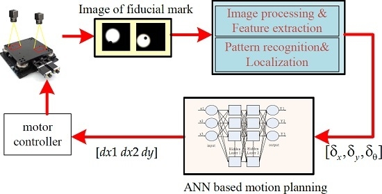
Before the alignment using the XXY stage is performed, the image processing and recognition are obtained according to the following steps: (1) teaching the pattern of positioning mark; (2) capturing the images by dual GIGA-E CCDs; (3) spatial and frequency filtering; (4) binarization; (5) erosion and dilation; (6) recognizing the positioning mark from the region of interest (ROI) by the pattern matching method, (7) edge detecting the fiducial marks and obtaining the centers of the positioning marks; and (8) transforming the image coordinates to actual Cartesian coordinates. Object detection plays an important role in determining the localization of the alignment mark in this image processing problem. To achieve the image alignment, the most important point is the mark recognition at first. If the mark recognition method is robust and stable, the accuracy of mark recognition can be guaranteed.
Generally, the pattern image should be complete and clear enough for the precision alignment. The pattern of the target image should be obtained by image processing and it is usually called pattern teaching in the AOI software. First, the pattern image is acquired from the ROI as the target image and the captured image is processed by the binarization to become a binary image. After that, the binarized image is processed by morphologically processing to become a cleaner binary image and stored in the PC memory. Second, the binarized image is applied to perform pattern matching to find the located regions of the actual image which are similar to the target pattern image.
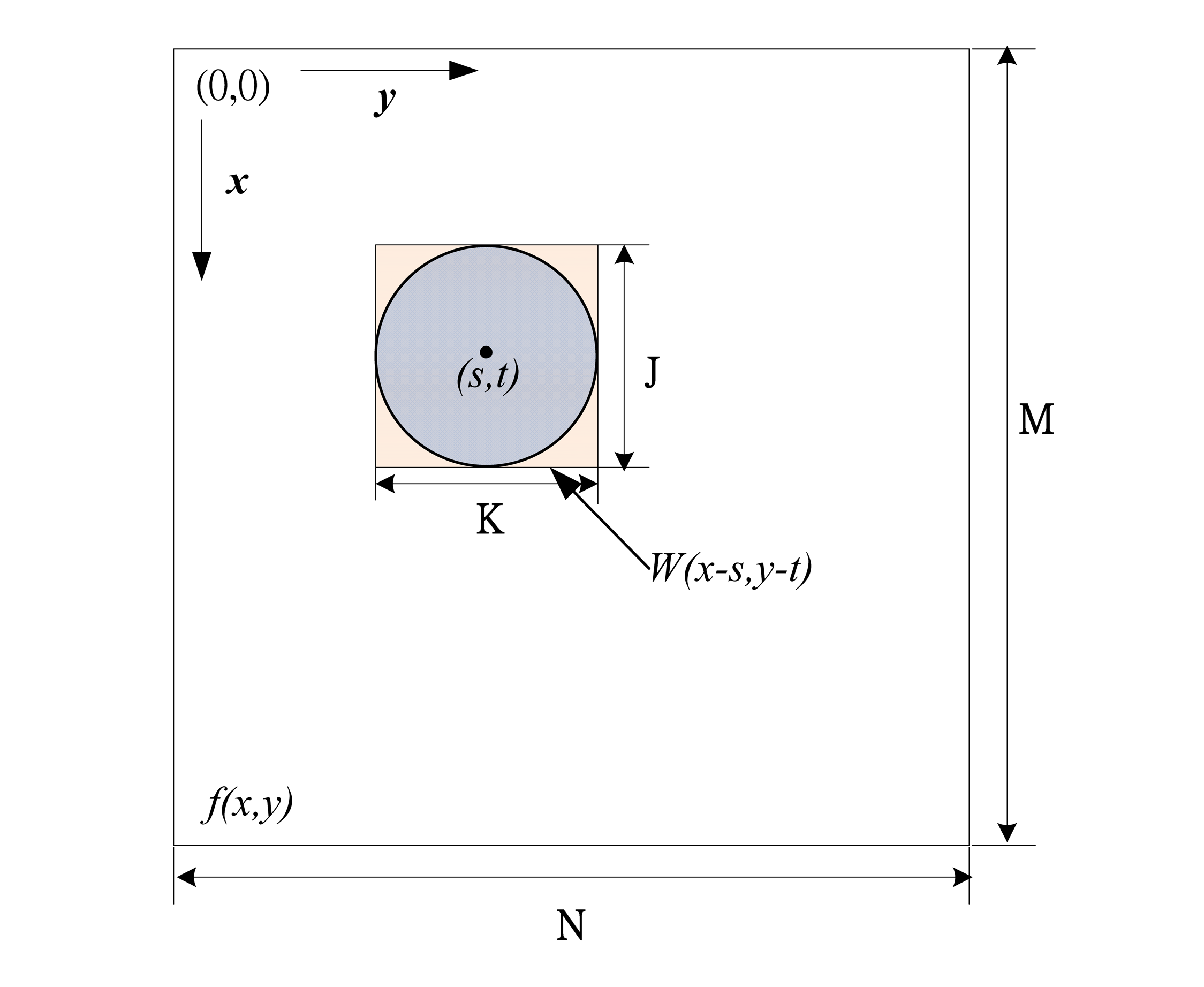
Figure 8 is used to describe the relationship between the testing image and the pattern where the gray value of the testing image to be searched at image pixel (x, y) is denoted by f(x, y) and that of the pattern image is denoted by w(x, y). In addition, the size of the testing image is denoted as M × N and the size of the pattern image is J × K. Therefore, the matched score R(x, y) between the pattern image and the testing image can be defined as follows.
R ( x , y ) = x y [ f ( s , t ) w ( x + s , y + t ) ] 2
Based on the above equation, the perfect match is when the value of R is zero. Otherwise, the larger R means that the matching case is worse. The above method is called the square difference matching method [11]. Different from the above method, there is another popular method which uses the normalized correlation coefficient (NCC) between the pattern image and the searched image to determine the matching score; this method is called the NCC matching method [17]. The definition of the NCC is described as follows.
r ( s , t ) = x y [ f ( x , y ) f ¯ ] × [ w ( x s , y t ) w ¯ ] { x y [ f ( x , y ) f ¯ ] 2 x y [ w ( x s , y t ) w ¯ ] 2 } 1 2
where s = 0, 1, 2, …, M − 1, t = 0, 1, 2, …, N − 1, w ¯ is the average gray-level value of the pattern, w(x, y), and f ¯ is the average gray-level value of the testing image f(x, y). The NCC value has two characteristic properties: (1) the correlation coefficient r(s, t) is normalized in the range between −1 and +1; (2) the larger r(s, t) implies the larger pattern matching. In this study, the NCC method is applied to find the fiducial mark. 
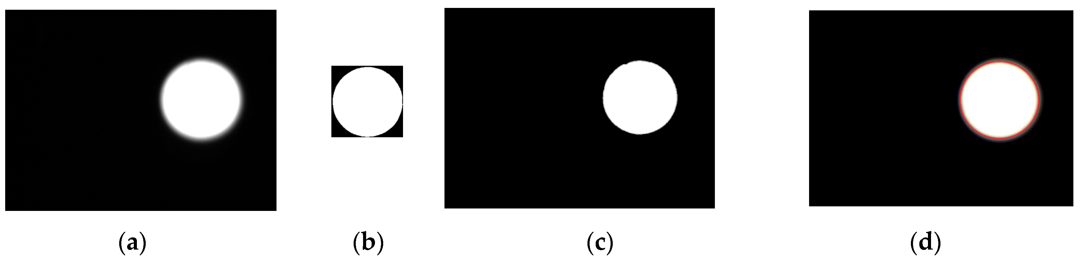
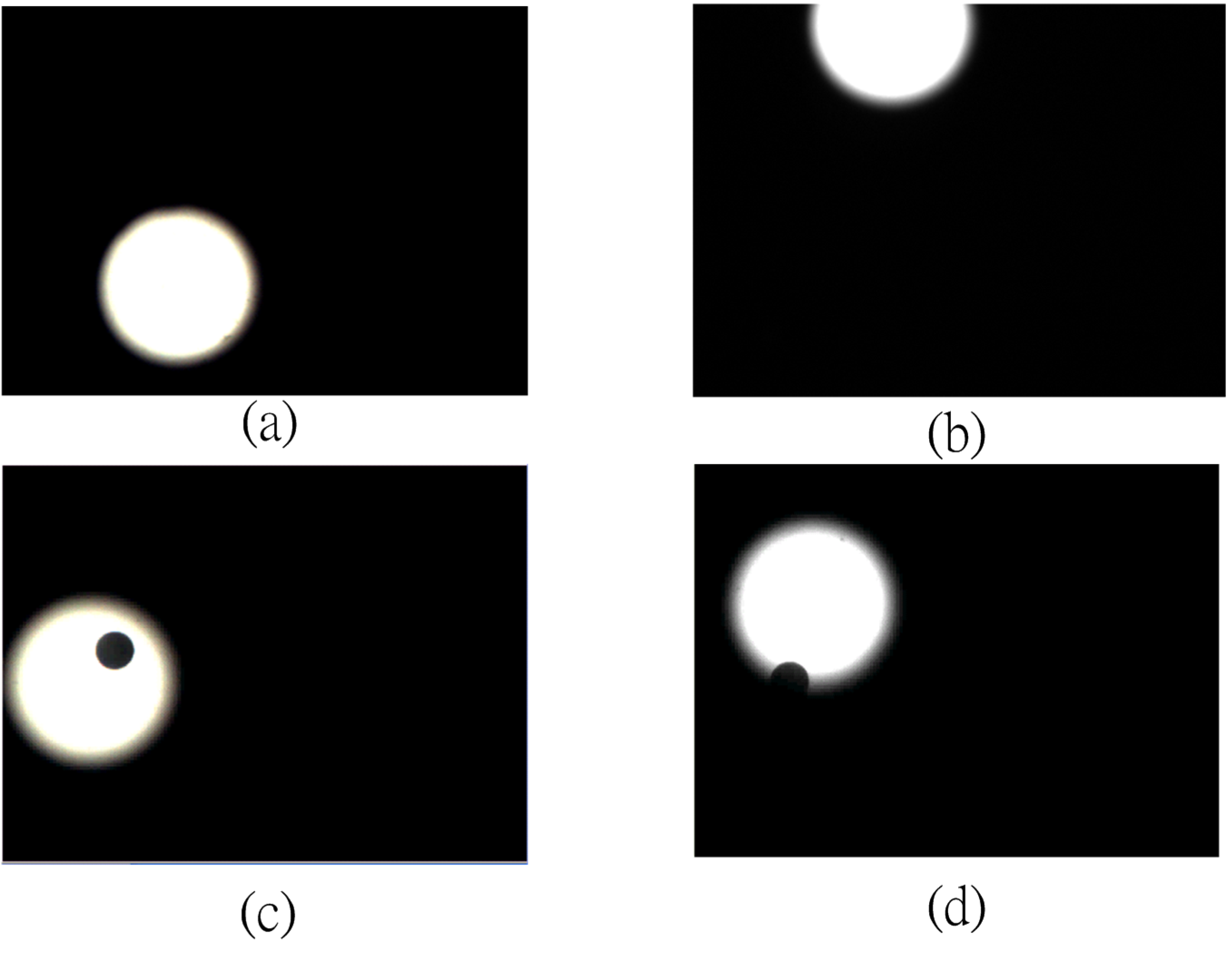
Figure 9 illustrates a pattern matching case by the NCC method; Figure 9a is the actual testing image and Figure 9b is the pattern image which is binarized. Figure 9c shows that the captured image is binarized and the pattern matching result using the NCC method is shown in Figure 9d (the red circle is used to mark the matched image).
Figure 8. Correlation between w(x, y) and f(x, y).
Applsci 06 00042 g008
Figure 9. Pattern recognition steps: (a) Original image; (b) Pattern image; (c) Binarization of original; (d) searched pattern.
Applsci 06 00042 g009
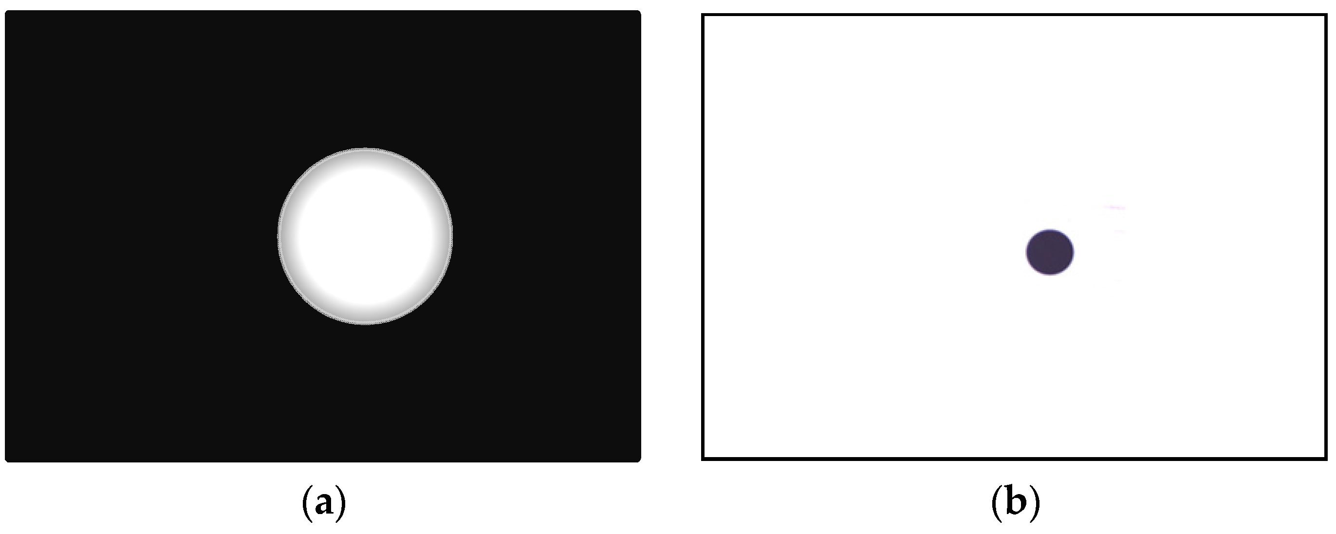
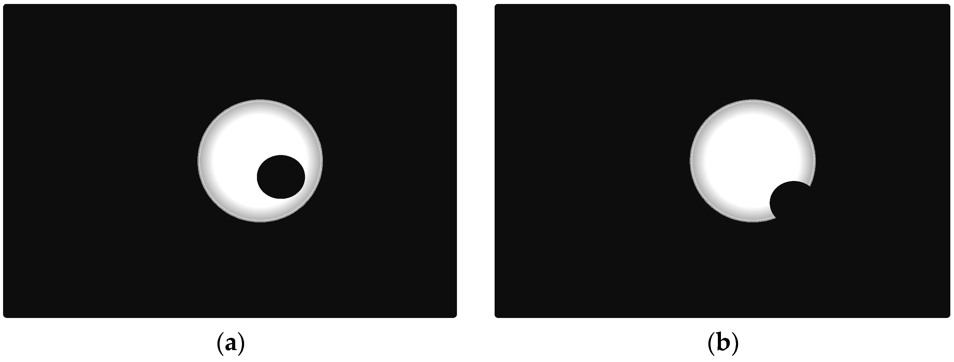
It is easy for the pattern recognition if there is only one fiducial mark that must be identified. However, to increase the speed of the image-servo mask alignment, the proposed method must capture the upper mark and the lower mark in the one shot. Therefore, some other problems should be solved; for example, the first problem of the halo effect results from the upper and lower masks being located in different depths of field as shown in Figure 10a. The second problem is that the lower mark may be covered by the upper mark in some cases as shown in Figure 10b. Therefore, solutions for these two problems are proposed as follows. To achieve the precision alignment task, it is important to determine the position of each fiducial marker with high accuracy. Detection of objects can be performed by using pattern recognition techniques such as neural networks [18,19], linear filters [20], support vector machines [21], and the Hough Transform [22]. As the positions of the objects need to be determined with sub-pixel precision, an accurate estimate can be obtained by computing its center of gravity [17]. However, for the case of Figure 11b, there are two recognized marks and one of the patterns is an incomplete circle; the COG method could cause a large positioning error for the incomplete circular mark. In that case, the generalized Hough Transform (GHT) is studied to find the dual positioning marks in this paper.
Hough Transform (HT) is proposed by P.V. C. Hough in 1972 and this method can be used to detect the line, circle and arbitrary shape [22,23]. To find the circle using circle HT, the first step is to make all edge points connected together to form a closed border; the second step is transferring the coordinates (x, y) of all points son the border to the space of parameter (a, b, r); the final step is to obtain the intersection of all cone which is transferred according to all points on the border. For example, consider a circle equation as follows.
( x a ) 2 + ( y b ) 2 = r 2
where (a, b, r) is the vector of the center of circle with its radius. The circle HT is to represent Equation (7) to the parameter space as follows.
H ( x , y , a , b , r ) = ( x a ) 2 + ( y b ) 2 r 2 = 0
To find the intersection point in this parameter space H(x, y, a, b, r), an accumulator matrix is needed and the parameter space is divided into “buckets” using a grid. Initially, all elements in the matrix are zeros. Then, each edge point in the original space (x, y) is substituted into the parameter space to obtain the corresponding parameter (a, b, 
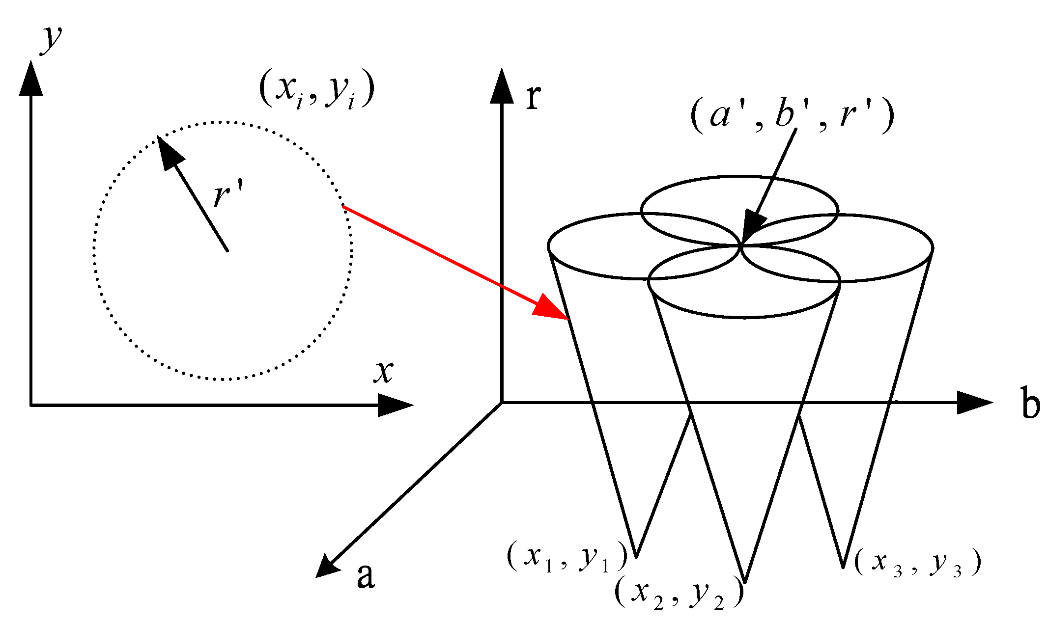
r). The accumulator matrix is used to count the number of “circles” in that passing through the corresponding grid cell in the parameter space and the number is called “voting number”. After voting, the position of the local maxima in the accumulator matrix represents the circle centers in the original space. To illustrate how to use the circle HT, assume that three points (x1, y1), (x2, y2), (x3, y3) are located at a circle with its radius of r′. The solution of (a, b) for these three points can be described by three cones. Therefore, the intersection of these three cones is the center of the circle (a′, b′) as shown in Figure 11.
Figure 10. (a) The halo effect of dual marks; (b) the partial lower mark in the upper mark.
Applsci 06 00042 g010
Figure 11. Cones of the three edge points in the parameter space.
Applsci 06 00042 g011

3.2. Image Recognition Using COG and GHT

To compare the difference between the COG method and the generalized HT (GHT) method for the image recognition, four case studies are designed to check the robustness of these two methods. As shown in Figure 12, the first case is the normal situation of the lower circle mark; the second case is the special situation of the partial lower circular mark; the third is the normal situation with the upper and lower marks; the fourth is the special situation of the full upper mark with the partial lower mark. Table 7 shows the experimental results for these two methods (COG, GHT), where the resulting data is the average root mean square error of 100 different experiments with the same situation. For Case 1 with the full circle mark, the COG is much better than the GHT. However, for Case 2 with the partial circle mark, the error of the COG is the two times that of the GHT. After comparing the results with the upper mark, Case studies 3 and 4 are used to examine the image recognition for the cases with the upper and lower marks. The GHT is better than the COG in Cases 3 and 4. According to the results summarized in Table 1, whether the lower mark is full or partial, the experimental results show that the GHT has a smaller error than the COG.
Figure 12. Image example of (a) full upper mark; (b) the partial upper mark; (c) the ideal alignment pair; and (d) the partial lower mark within the full upper mark.
Applsci 06 00042 g012
Table 7. Comparison between COG and GHT.
MethodsCOGGHT
Case studies
Case 11.03.6
Case 215.18.7
Case 34.13.6
Case 45.03.8
(Unit: pixel, 1 pixel = 5.74 μm).

4. Image-Servo Alignment Compensation Design

After the positioning marks are recognized by the image processing, the actual orientation difference should be computed based on the relationships of the positioning marks. The translation and rotation relationships can be obtained by the following equations as shown in Figure 13. Figure 13 shows that each black block represents the field of view (FOV) of each CCD for this study. The green block represents the original position of the lower mask carried by the XXY stage and the red block is the target position to be aligned. To compute the command of the XXY stage to make the lower mask align with the upper mask (the red block), the green dot is the fiducial mark for the lower mask and the red circle is the fiducial mark of the upper target to be aligned. After obtaining the image positions in the ROI using the above GHT method, the self-developed code is used to transfer the masks’ positions in the image space to the Cartesian-space’s coordinates. In Figure 13, (x1, y1) and (x3, y3) represents the initial coordinates of the lower fiducial marks; (x2, y2) and (x4, y4) are the target coordinates of the upper fiducial marks.
Figure 13. Kinematic relationship of XXY stage for image servo alignment.
Applsci 06 00042 g013
To make the lower mask align with the upper mask, the motors’ command of the XXY stage m = [dx1 dx2 dy]T is needed to achieve the alignment task. If the desired translation and angular displacement of the stage [δx δy δθ]T is known, the command m can be obtained from Equation (7). In fact, the desired [δx δy δθ]T can be obtained according to the relationship between [(x1, y1), (x3, y3)] and [(x2, y2), (x4, y4)] as follows. From Figure 11, the blue block using dotted line represents only translation movement with t = [ δ x δ y ] T and the final target orientation is the red block which is the form of giving the blue block a rotational movement of δθ. Therefore, the kinematic relationship can be described as follows.
t = q 1 + c 1 q 1 t = q 2 + c 2 q 2
where c 1 = [ x 2 , y 2 ] T [ x 1 , y 1 ] T , c 2 = [ x 4 , y 4 ] T [ x 3 , y 3 ] T are obtained by AOI code and q 1 , q 2 are system parameters and known. Without considering the rotational movement, there is only translation movement which implies that t = c 1 = c 2 , where q 1 = q 1 , q 2 = q 2 . Now, consider the rotational movement δθ between q 1 and q 1 as the same as q 2 and q 2 . We have
q 1 = R q 1 q 2 = R q 2
where
R = [ cos δ θ sin δ θ sin δ θ cos δ θ ]
Therefore, from Equations (9)–(11), the following equation can be obtained.
t = q 1 + c 1 R q 1 = q 2 + c 2 R q 2
From Equation (12), the angular displacement δθ can be obtained according to the following equation.
[ 1 cos δ θ sin δ θ sin δ θ 1 cos δ θ ] ( q 1 q 2 ) = ( c 2 c 1 ) ( I R ) ( q 1 q 2 ) = c 2 c 1
After knowing the angular displacement δθ, the translation displacement t = [ δ x δ y ] T can be obtained from Equation (12). Substituting [ δ x δ y δ θ ]T into the proposed ANN method can obtain the motors’ command. The alignment compensation steps are described in Figure 14. To test the robustness of the proposed method, Case 2 with the partial circle mark in Figure 12b is used to perform the alignment tests for these two methods (COG and GHT). The experimental results of the translation and rotational errors for 30 random alignment tasks and the comparisons between two methods are shown in Figure 15 and Figure 16. From the experimental results, the proposed method using GHT has much better alignment precision than the traditional COG method. To achieve the better precision for the image-servo alignment tasks, there are two alignments performed in each testing. Table 8 summaries the experimental results of the root-mean-square error (RMSE) and the maximal alignment error for using COG and GHT. The experimental results also validate that the proposed method using GHT is better than the COG method. The computation time of the GHT method is a little longer than the COG method.
Figure 14. Procedures of the proposed alignment compensation.
Applsci 06 00042 g014
Figure 15. Translation errors for the COG and GHT.
Applsci 06 00042 g015
Figure 16. Rotational errors for the COG and GHT.
Applsci 06 00042 g016
Table 8. Results of the proposed method using COG and GHT.
MethodCOGGHT
Alignment error 1st Alignment2nd Alignment1st Alignment2nd Alignment
RMSE of Translation (μm)96.919.942.515.8
Max Error of Translation (μm)194.041.879.829.1
RMSE of Rotation0.50°0.033°0.151°0.023°
Max Error of Rotation1.02°0.091°0.284°0.056°
Average of image-servo alignment time1.302 s0.358 s1.310 s0.337 s

5. Conclusions

In this paper, the XXY stage is used to perform the XYΘ alignment task; however, the relationship between the XXY stage’s movement and the commands of the three motors is difficult to compute, because the movements of the three motors on the same plane are coupling. Therefore, an ANN-based motion planning method is studied to establish a nonlinear mapping from the desired position and orientation of the stage to the three motors’ commands. The experimental results validate that the proposed ANN-based motion planning has the smaller positioning and rotational error than the linear approximated method. On the other hand, the image processing method of the COG and GHT are studied to recognize the center of the upper and lower positioning marks. For the COG method, the partial circular image leads to mismatching in the data, and the experimental results show that the COG has the greatest error. In contrast to the COG, the GHT can obtain the correct center of circle mark according to the partial curve of the circle. The computation time of the GHT method is almost the same as that of the COG method. The experimental results of the alignment tasks also validate that the proposed method using the GHT has better alignment performance than the traditional COG method.

Acknowledgments

The authors would like to thank the National Science Council of the Republic of China, Taiwan for financially/partially supporting this research under Contract No. MOST 104-2221-E-027-026.

Author Contributions

Chih-Jer Lin conceived and designed the experiments; Hui-Hsiang Hsu and Yu-Chung Li performed the experiments; Chiang-Ho Cheng contributed reagents/materials/analysis tools; Hui-Hsiang Hsu analyzed the data; Chih-Jer Lin wrote the paper.

Conflicts of Interest

The authors declare no conflict of interest.

References

  1. Sanderson, A.C.; Weiss, L.E. Image-based visual servo control of robots. In Proceedings of the SPIE 0360, Robotics and Industrial Inspection, San Diego, CA, USA, 23 May 1983. [CrossRef]
  2. Kim, H.T.; Song, C.S.; Yang, H.J. 2-step algorithm of automatic alignment in wafer dicing process. Microelectron. Reliab. 2004, 44, 1165–1179. [Google Scholar] [CrossRef]
  3. Kim, H.T.; Lee, K.W.; Jeon, B.K.; Song, C.S. Quick wafer alignment using feedforward neural networks. IEEE Trans. Autom. Sci. Eng. 2010, 7, 377–382. [Google Scholar]
  4. Yang, C.M.; Wen, C.C.; Lin, S.W.; Chang, C.C.; Lin, C.T. Application of image servo alignment module design to automatic laminating machine for touch penal. Smart Sci. 2013, 1, 75–81. [Google Scholar]
  5. Lin, C.J.; Yu, S.K.; Li, Y.C.; Yang, C.W. Design and control of an optical alignment system using a XXY stage integrated with dual CCDs. Smart Sci. 2014, 2, 160–167. [Google Scholar]
  6. Cohen, M.S.; Cina, M.F. Packaging of high-density fiber/laser modules using passive alignment techniques. IEEE Trans. Compon. Hybrids Manuf. Technol. 1992, 15, 17–30. [Google Scholar] [CrossRef]
  7. Tichem, M.; Cohen, M.S. Sub μm registration of fiducial marks using machine vision. IEEE Trans. Pattern Anal. Mach. Intell. 1994, 16, 791–794. [Google Scholar] [CrossRef]
  8. Fernandez, X.; Amat, J. Research on Small Fiducial Mark Use for Robotic Manipulation and Alignment of Ophthalmic Lenses. In Proceedings of the IEEE International Conference on Emerging Technologies and Factory Automation, Barcelona, Spain, 18–21 October 1999; pp. 1143–1146.
  9. Kuo, W.M.; Chuang, S.F.; Nian, C.Y.; Tarng, Y.S. Precision nano-alignment system using machine vision with motion controlled by piezoelectric motor. Mechatronics 2008, 18, 21–34. [Google Scholar] [CrossRef]
  10. Lin, C.J.; Chen, G.Z.; Huang, Y.X.; Chang, J.K. Computer-integrated micro-assembling with image-servo system for a microdroplet ejector. J. Mater. Process. Technol. 2008, 20I, 689–694. [Google Scholar] [CrossRef]
  11. Lee, H.W.; Liu, C.H. Vision servo motion control and error analysis of a coplanar XXY stage for image alignment motion. Math. Probl. Eng. 2013, 2013. [Google Scholar] [CrossRef]
  12. Huang, S.J.; Lin, S.Y. Application of visual servo-control X-Y table in color filter cross mark alignment. Sens. Actuators A 2009, 152, 53–62. [Google Scholar] [CrossRef]
  13. Multi-Axis Mask Aligner. Available online: http://www.aerotech.com/product-catalog/custom-systems/multi-axis-mask-aligner.aspx (accessed on 27 January 2016).
  14. XXY-NR1 Series. Available online: http://www.aafteck.com/s/en/2/product/XXY-Precision-Alignment-Stage-XXY-NR1-180-426058.html (accessed on 27 January 2016).
  15. Hutchinson, S.; Hager, G.D.; Corke, P.I. A tutorial on visual servo control. IEEE Trans. Robot. Autom. 1996, 12, 651–670. [Google Scholar] [CrossRef]
  16. Raghvendra, V.C.; Panagiotis, T. Hierarchical motion planning with dynamical feasibility guarantees for mobile robotic vehicles. IEEE Trans. Robot. 2012, 28, 379–395. [Google Scholar]
  17. Gonzalez, R.C.; Woods, R.E. Digital Image Processing; Addison-Wesley: Reading, MA, USA, 1992. [Google Scholar]
  18. Egmont-Petersen, M.; Arts, T. Recognition of radiopaque markers in X-ray images using a neural network as nonlinear filter. Pattern Recognit. Lett. 1999, 20, 521–533. [Google Scholar] [CrossRef]
  19. Egmont-Petersen, M.; Schreiner, U.; Tromp, S.C.; Lehmann, T.M.; Slaaf, D.W.; Arts, T. Detection of leukocytes in contact with the vessel wall from in vivo microscope recordings using a neural network. IEEE Trans. Biomed. Eng. 2000, 47, 941–951. [Google Scholar] [CrossRef] [PubMed]
  20. Sjoberg, H.; Goudail, F.; Refregier, P. Comparison of the maximum likelihood ratio test algorithm and linear filters for target location in binary images. Opt. Commun. 1999, 163, 252–258. [Google Scholar] [CrossRef]
  21. Pontil, M.; Verri, A. Support vector machines for 3D object recognition. IEEE Trans. Pattern Anal. Mach. Intell. 1998, 20, 637–646. [Google Scholar] [CrossRef]
  22. Hough, P.V.C. A Method and Means for Recognizing Complex Patterns. US Patent Application No. 3069654, 18 December 1962. [Google Scholar]
  23. Ballard, D.H. Generalizing the Hough transform to detect arbitrary shapes. Pattern Recognit. 1981, 13, 110–122. [Google Scholar] [CrossRef]

