
A Novel Coordinated Control Strategy for Parallel Hybrid Electric Vehicles during Clutch Slipping Process

 ,
,  and
and
Abstract
:1. Introduction
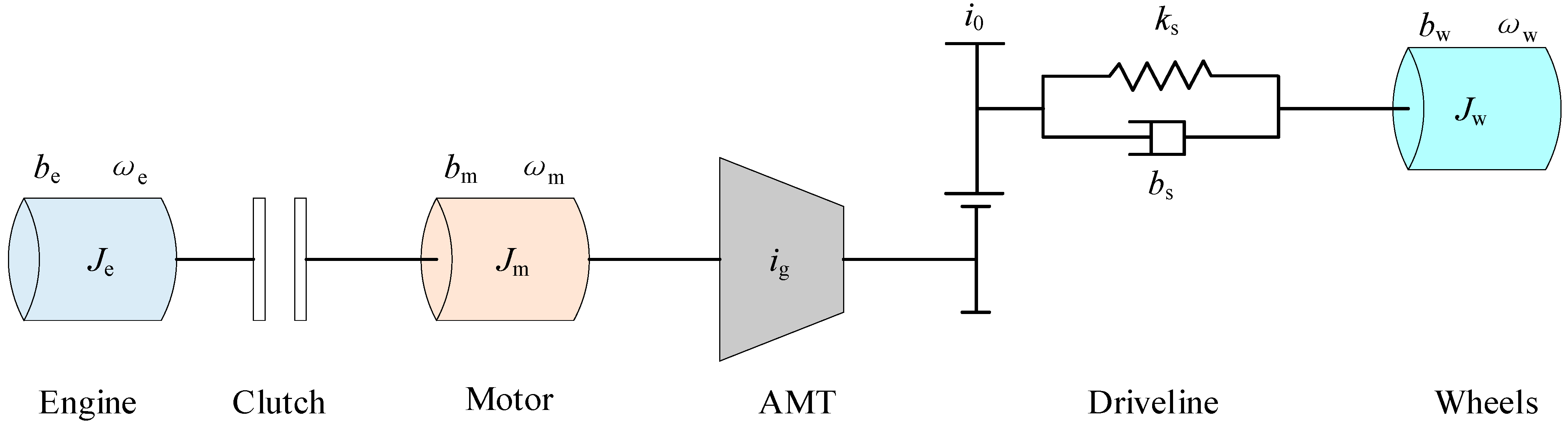
2. Parallel HEV System Model
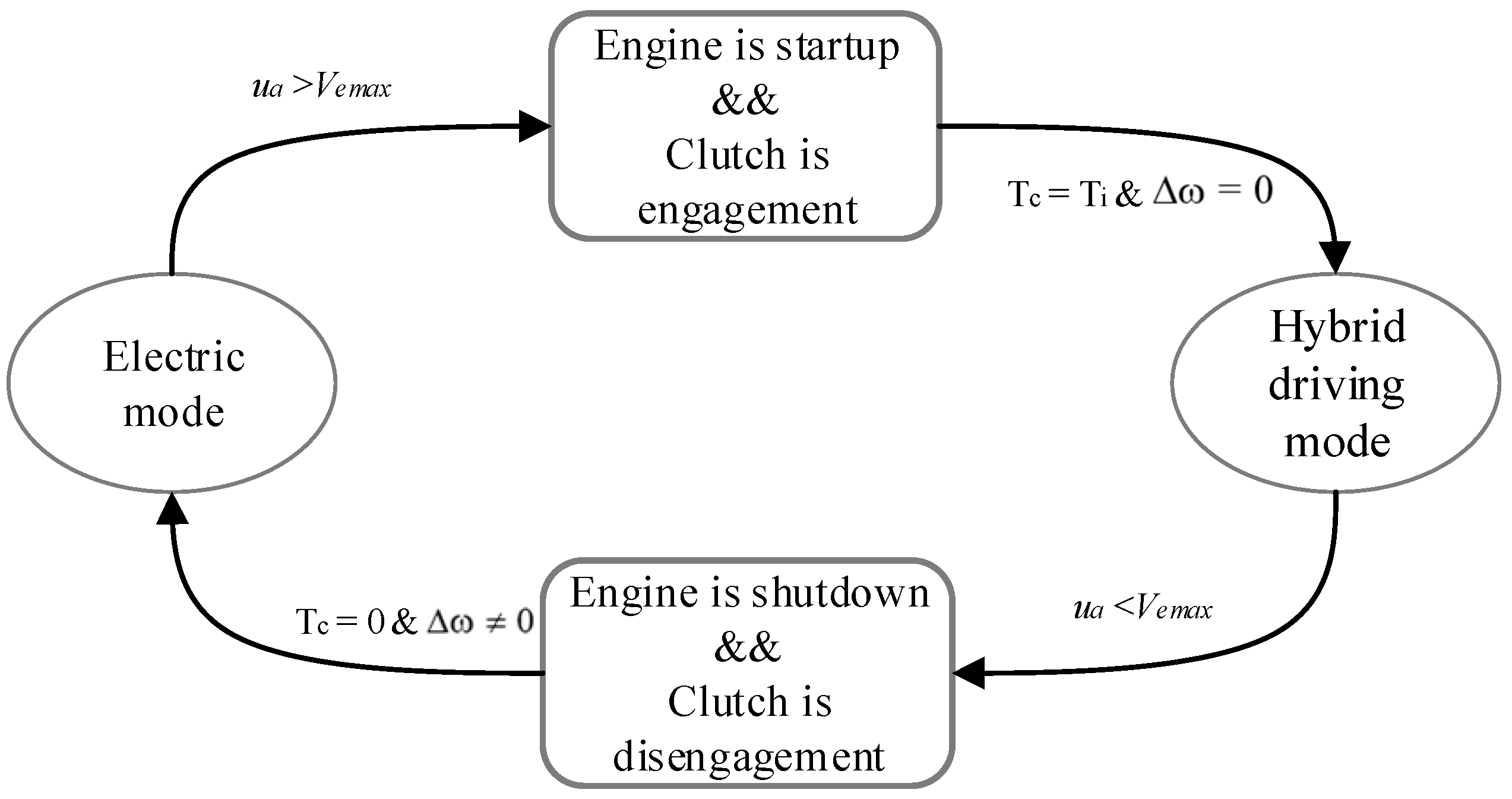
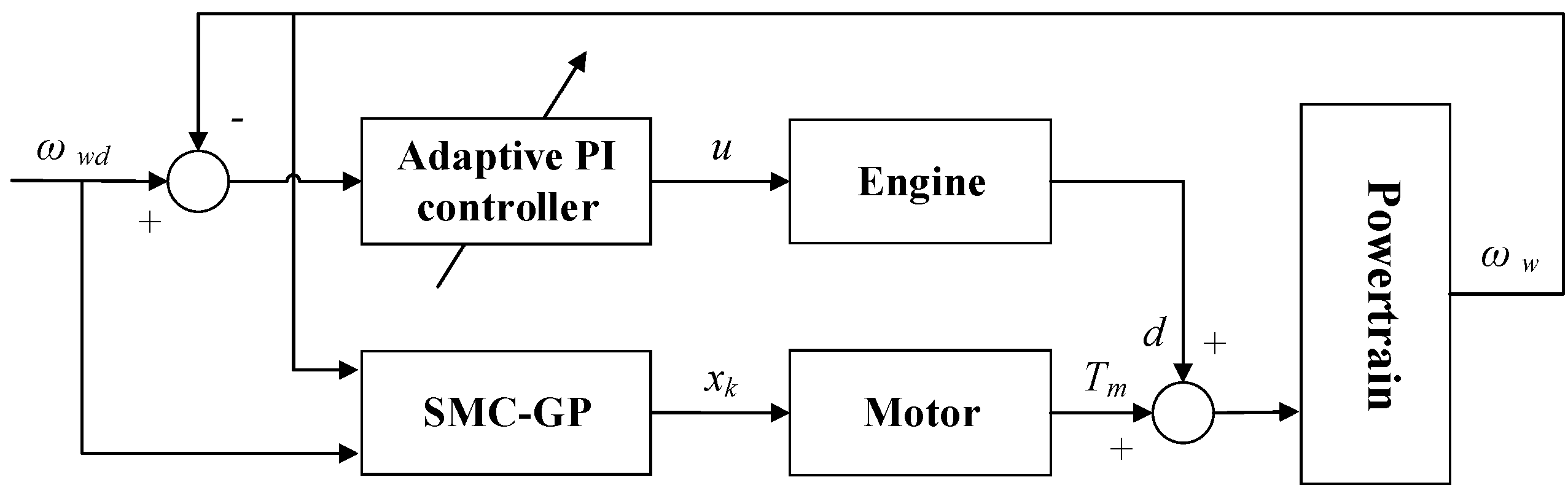
3. Control Strategy Description
3.1. Control Strategy for the Motor
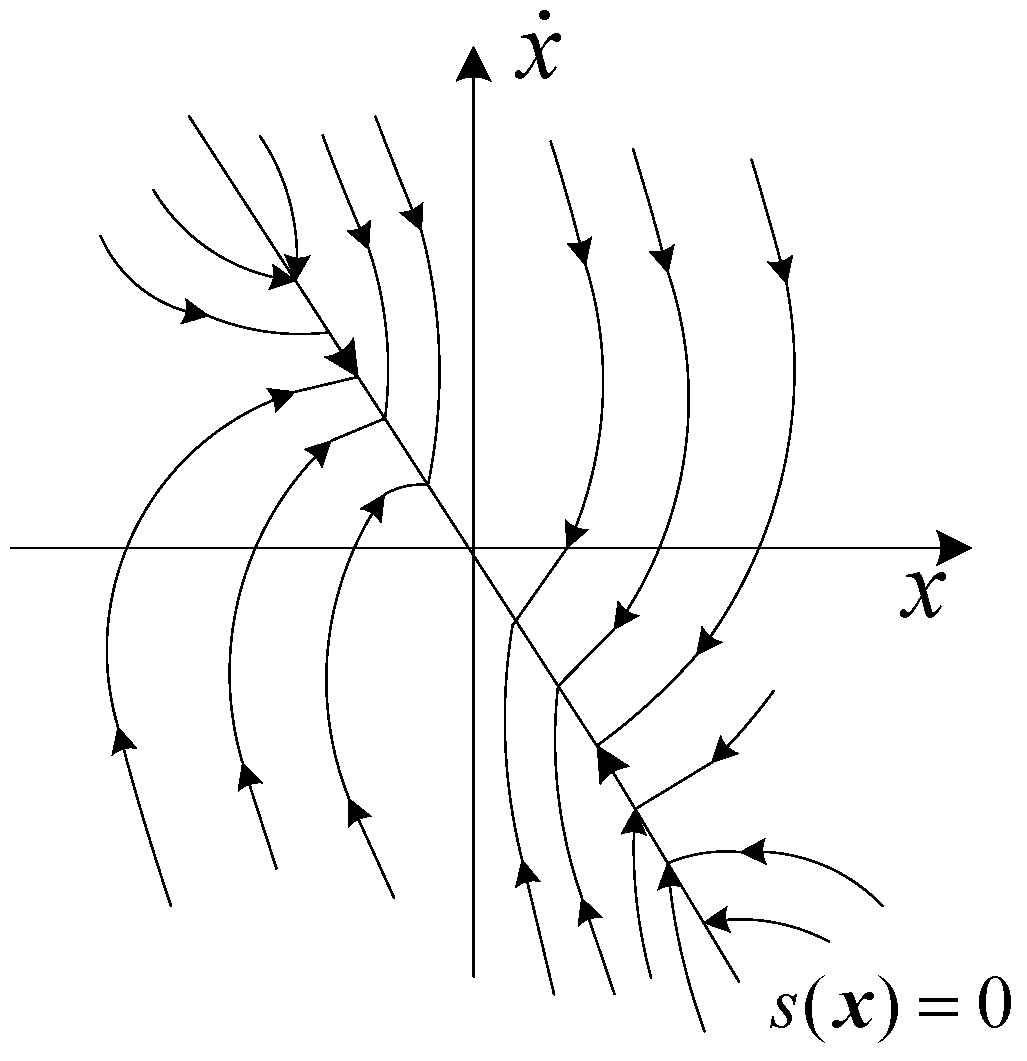
3.1.1. SMC Strategy
3.1.2. GP-SMC Strategy
3.2. Control Strategy for the Engine
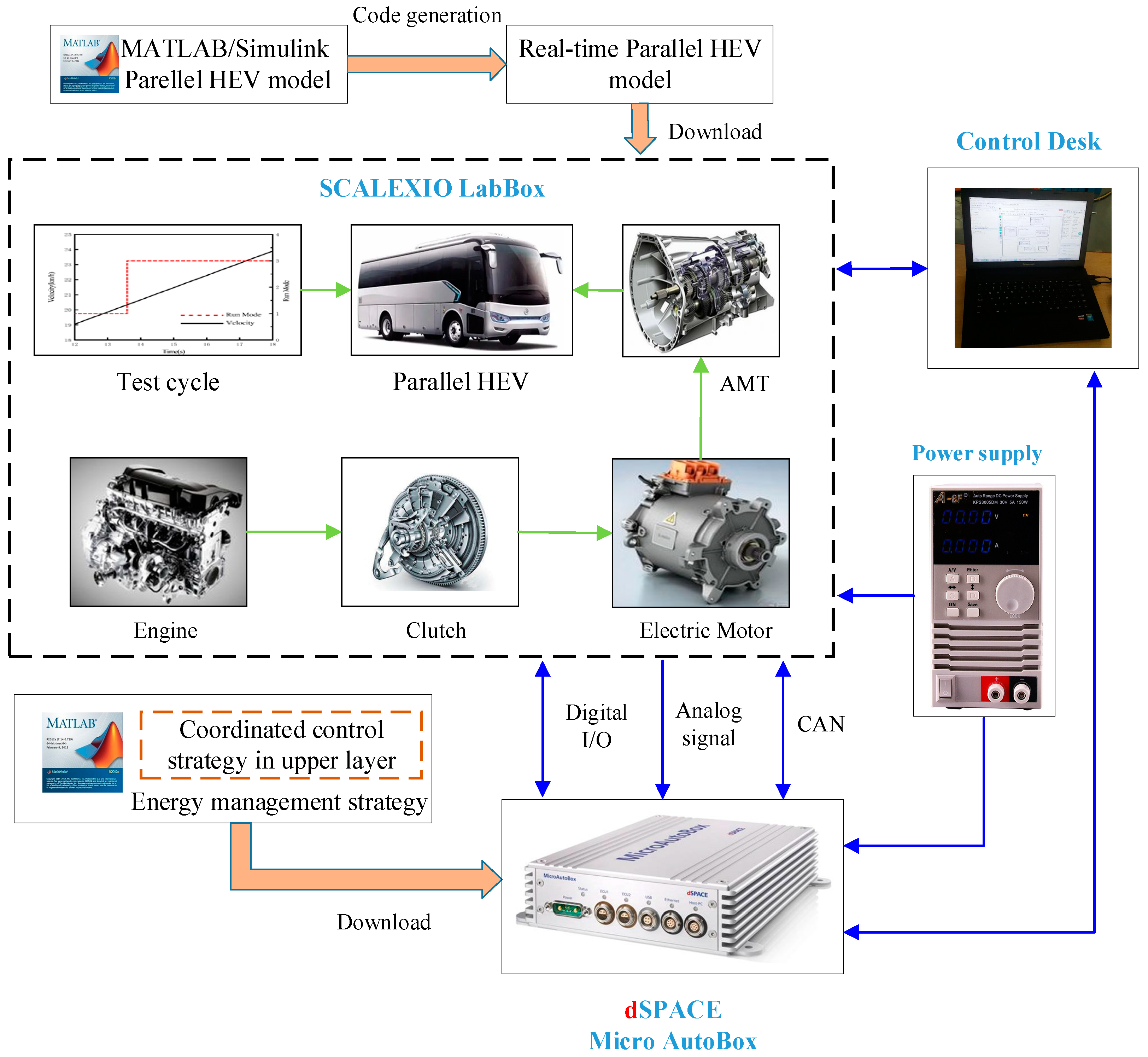
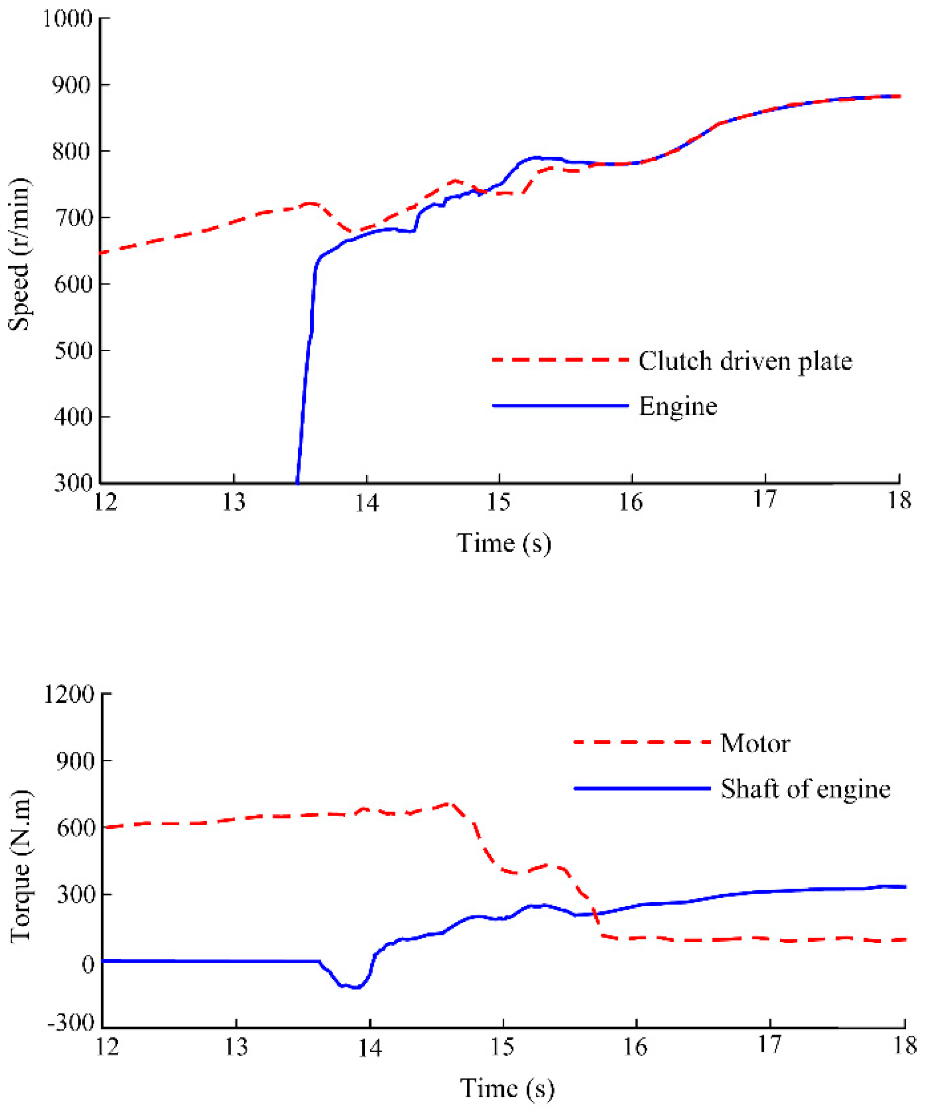
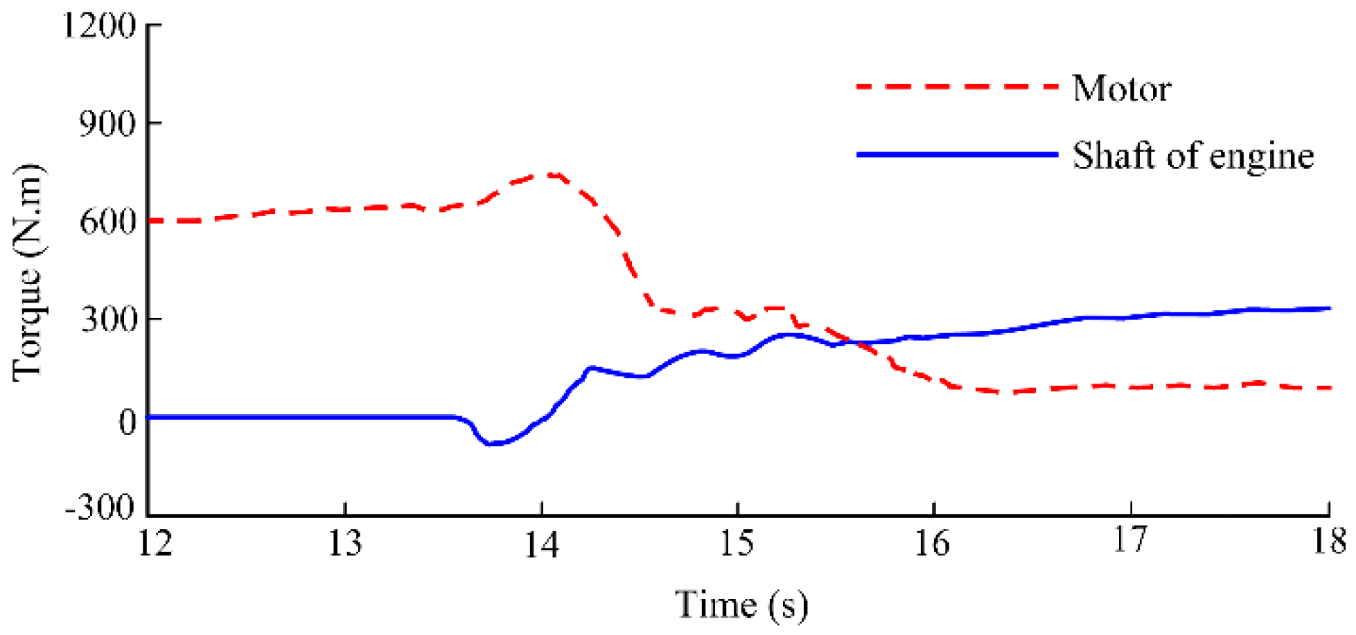
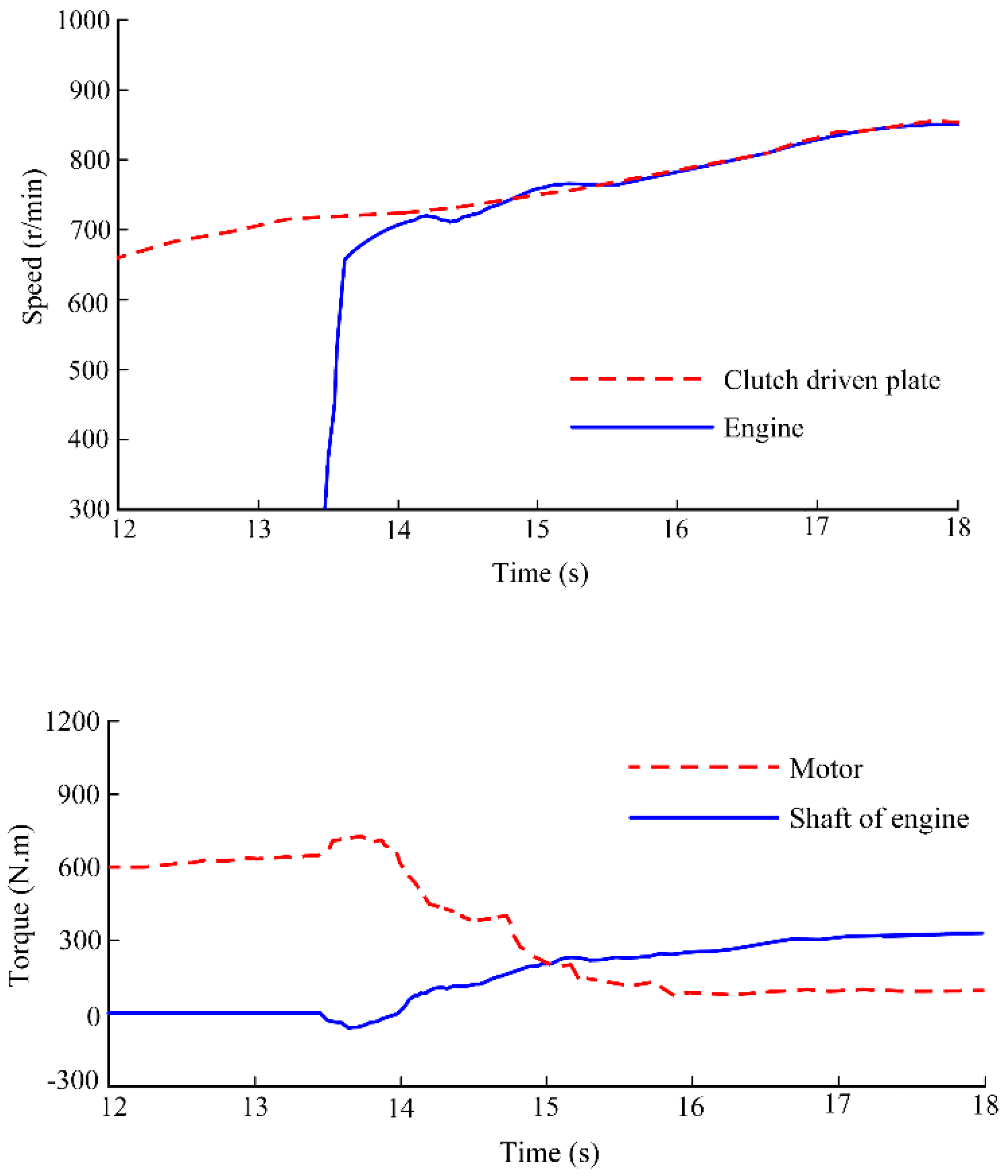
4. Results and Discussion
5. Conclusions
Author Contributions
Funding
Institutional Review Board Statement
Informed Consent Statement
Data Availability Statement
Conflicts of Interest
Nomenclature
| t | combined inertia of the engine and accessories |
| Jw | inertia of wheels |
| ωm | motor speed |
| bm | motor internal friction coefficient |
| bw | tire damping coefficient |
| i0 | gear ratio of the final drive |
| ks | spring coefficient of the driveline |
| Te | engine torque |
| Tc | clutch torque |
| g | gravity acceleration |
| fr | rolling resistance coefficient |
| A | frontal area |
| va | vehicle velocity |
| Ti | input torque of the driving plate |
| Nc | friction plate number |
| R | outer radius of the diaphragm spring |
| △ω | speed difference |
| u(t) | control input |
| tf | terminal time |
| U | maximum of control input |
| α | positive constant |
| xd | ideal trajectory |
| k | constant with a positive value |
| d | disturbance |
| σ | positive constant with a smaller value |
| Tm_max | maximum motor torque |
| λk,1 | regulation coefficient for slope value 1 |
| λk,2 | regulation coefficient for slope value 2 |
| λk,3 | regulation coefficient for slope value 3 |
| Ki | integral coefficient |
| e(t) | speed error at the time t |
| Kp_min | minimum of the parameter Kp |
| Ki_min | minimum of the parameter Ki |
| yn | fuzzy singletons |
| M | number of inference rules |
| v | vehicle velocity determined by the driving cycle |
| t1 | initial time of the clutch slipping process |
| J | vehicle jerk |
| N | iteration number |
| Jm | combined inertia of the motor rotor and transmission |
| ωe | engine speed |
| ωw | wheel speed |
| be | engine friction coefficient |
| ig | gear ratio of the AMT |
| bs | equivalent damping coefficient of the driveline |
| θs | torsional displacement of the driveshaft |
| Tm | motor torque |
| TL | vehicle load torque |
| m | gross mass |
| θ | road slope angle |
| CD | air drag coefficient |
| δ | modified coefficient of the rotating mass |
| uc | clutch friction coefficient |
| Fc | normal force |
| r | inside radius of the diaphragm spring |
| x(t) | system state |
| t0 | initial time |
| J(u) | performance function |
| M0 | positive constant |
| S(x) | sliding surface |
| ωwd | expected wheel speed |
| u1 | control law |
| χ | positive constant |
| Rw | wheel radius |
| h | step size |
| Kp | proportional coefficient |
| ωe_cmd | target speed for engine |
| Kp_max | maximum of the parameter Kp |
| Ki_max | maximum of the parameter Ki |
| fuzzy sets | |
| xi | input variable |
| a | vehicle acceleration |
| Wf | clutch frictional loss |
| t2 | end time of the clutch slipping process |
| F(x(tf), tf) | terminal index function |
| L(x, u, t) | Lagrange function |
References
- Agamloh, E.; Von Jouanne, A.; Yokochi, A. An Overview of Electric Machine Trends in Modern Electric Vehicles. Machines 2020, 8, 20. [Google Scholar] [CrossRef]
- Tian, X.; Cai, Y.; Sun, X.; Zhu, Z.; Xu, Y. A Novel Energy Management Strategy for Plug-in Hybrid Electric Buses Based on Model Predictive Control and Estimation of Distribution Algorithm. IEEE/ASME Trans. Mechatron. 2022, 1–12. [Google Scholar] [CrossRef]
- Mercorelli, P. Parameter identification in a permanent magnet three-phasesynchronous motor of a city bus for an intelligent drive assistant. Int. J. Model. Identif. Control 2014, 21, 352–361. [Google Scholar] [CrossRef]
- Wang, Z.; Cai, Y.; Zeng, Y.; Yu, J. Multi-objective optimization for plug-in 4WD hybrid electric vehicle powertrain. Appl. Sci. 2019, 9, 4068. [Google Scholar] [CrossRef]
- Morales-Morales, J.; Rivera-Cruz, M.A.; Cruz-Alcantar, P.; Santos, H.B.; Cervantes-Camacho, I.; Herrera, V.A.R. Performance Analysis of a Hybrid Electric Vehicle with Multiple Converter Configuration. Appl. Sci. 2020, 10, 1074. [Google Scholar] [CrossRef]
- Ebbesen, S.; Elbert, P.; Guzzella, L. Battery State-of-Health Perceptive Energy Management for Hybrid Electric Vehicles. IEEE Trans. Veh. Technol. 2012, 61, 2893–2900. [Google Scholar] [CrossRef]
- Tang, X.; Yang, W.; Hu, X.; Zhang, D. A novel simplified model for torsional vibration analysis of a series-parallel hybrid electric vehicle. Mech. Syst. Signal Process. 2017, 85, 329–338. [Google Scholar] [CrossRef]
- Nüesch, T.; Elbert, P.; Flankl, M.; Onder, C.H.; Guzzella, L. Convex Optimization for the Energy Management of Hybrid Electric Vehicles Considering Engine Start and Gearshift Costs. Energies 2014, 7, 834–856. [Google Scholar] [CrossRef]
- Sun, X.; Shi, Z.; Zhu, J. Multiobjective Design Optimization of an IPMSM for EVs Based on Fuzzy Method and Sequential Taguchi Method. IEEE Trans. Ind. Electron. 2020, 68, 10592–10600. [Google Scholar] [CrossRef]
- Koprubasi, K.; Westervelt, E.R.; Rizzoni, G. Toward the Systematic Design of Controllers for Smooth Hybrid Electric Vehicle Mode Changes. In Proceedings of the 2007 American Control Conference, New York, NY, USA, 9–13 July 2007; pp. 2985–2990. [Google Scholar] [CrossRef]
- Chen, L.; Xi, G.; Sun, J. Torque Coordination Control During Mode Transition for a Series–Parallel Hybrid Electric Vehicle. IEEE Trans. Veh. Technol. 2012, 61, 2936–2949. [Google Scholar] [CrossRef]
- Zhang, H.; Wang, C.-L.; Zhang, Y.; Liang, J.-Y.; Yin, C.-L. Drivability improvements for a single-motor parallel hybrid electric vehicle using robust controls. J. Zhejiang Univ. A 2014, 15, 291–301. [Google Scholar] [CrossRef]
- Kim, H.; Kim, J.; Lee, H. Mode Transition Control Using Disturbance Compensation for a Parallel Hybrid Electric Vehicle. Proc. Inst. Mech. Eng. Part D J. Automob. Eng. 2011, 225, 150–166. [Google Scholar] [CrossRef]
- Yang, C.; Jiao, X.; Li, L.; Zhang, Y.; Chen, Z. A robust H∞ control-based hierarchical mode transition control system for plug-in hybrid electric vehicle. Mech. Syst. Signal Process. 2018, 99, 326–344. [Google Scholar] [CrossRef]
- Zeng, X.; Yang, N.; Wang, J.; Song, D.; Zhang, N.; Shang, M.; Liu, J. Predictive-model-based dynamic coordination control strategy for power-split hybrid electric bus. Mech. Syst. Signal Process. 2015, 60–61, 785–798. [Google Scholar] [CrossRef]
- Michalek, M.M.; Patkowski, B.; Gawron, T. Modular Kinematic Modelling of Articulated Buses. IEEE Trans. Veh. Technol. 2020, 69, 8381–8394. [Google Scholar] [CrossRef]
- Sun, X.; Cai, F.; Yang, Z.; Tian, X. Finite Position Control of Interior Permanent Magnet Synchronous Motors at Low Speed. IEEE Trans. Power Electron. 2022, 37, 7729–7738. [Google Scholar] [CrossRef]
- Suhail, M.; Akhtar, I.; Kirmani, S.; Jameel, M. Development of Progressive Fuzzy Logic and ANFIS Control for Energy Management of Plug-In Hybrid Electric Vehicle. IEEE Access 2021, 9, 62219–62231. [Google Scholar] [CrossRef]
- Tian, X.; He, R.; Sun, X.; Cai, Y.; Xu, Y. An ANFIS-Based ECMS for Energy Optimization of Parallel Hybrid Electric Bus. IEEE Trans. Veh. Technol. 2019, 69, 1473–1483. [Google Scholar] [CrossRef]
- Ji, Y.; Lee, H. Event-Based Anomaly Detection Using a One-Class SVM for a Hybrid Electric Vehicle. IEEE Trans. Veh. Technol. 2022, 71, 6032–6043. [Google Scholar] [CrossRef]
- Sun, X.; Shi, Z.; Cai, Y.; Lei, G.; Guo, Y.; Zhu, J. Driving-Cycle-Oriented Design Optimization of a Permanent Magnet Hub Motor Drive System for a Four-Wheel-Drive Electric Vehicle. IEEE Trans. Transp. Electrif. 2020, 6, 1115–1125. [Google Scholar] [CrossRef]
- Bhattacharjee, S.; Halder, S.; Yan, Y.; Balamurali, A.; Iyer, L.V.; Kar, N.C. Real-Time SIL Validation of a Novel PMSM Control Based on Deep Deterministic Policy Gradient Scheme for Electrified Vehicles. IEEE Trans. Power Electron. 2022, 37, 9000–9011. [Google Scholar] [CrossRef]
- Wang, L.; Zhang, Y.; Yin, C.; Zhang, H.; Wang, C. Hardware-in-the-loop simulation for the design and verification of the control system of a series–parallel hybrid electric city-bus. Simul. Model. Pract. Theory 2012, 25, 148–162. [Google Scholar] [CrossRef]
- Hong, S.; Kim, H.; Kim, J. Motor control algorithm for an optimal engine operation of power split hybrid electric vehicle. Int. J. Automot. Technol. 2015, 16, 97–105. [Google Scholar] [CrossRef]
- Sun, X.; Cao, J.; Lei, G.; Guo, Y.; Zhu, J. A Composite Sliding Mode Control for SPMSM Drives Based on a New Hybrid Reaching Law With Disturbance Compensation. IEEE Trans. Transp. Electrif. 2021, 7, 1427–1436. [Google Scholar] [CrossRef]
- Serrao, L.; Onori, S.; Rizzoni, G. A Comparative Analysis of Energy Management Strategies for Hybrid Electric Vehicles. J. Dyn. Syst. Meas. Control 2011, 133, 031012. [Google Scholar] [CrossRef]
- Sun, X.; Zhang, Y.; Lei, G.; Guo, Y.; Zhu, J. An Improved Deadbeat Predictive Stator Flux Control with Reduced-Order Disturbance Observer for In-Wheel PMSMs. IEEE/ASME Trans. Mechatron. 2021, 27, 690–700. [Google Scholar] [CrossRef]
- Pathmanathan, M.; Semsar, S.; Viana, C.; Lehn, P.W. Power Sharing Control Algorithm for Direct Integration of Fuel Cells in a Dual-Inverter Electric Vehicle Drivetrain. IEEE Trans. Transp. Electrif. 2022, 8, 2490–2500. [Google Scholar] [CrossRef]
- Zhou, Q.; Yao, D.; Wang, J.; Wu, C. Robust control of uncertain semi-Markovian jump systems using sliding mode control method. Appl. Math. Comput. 2016, 286, 72–87. [Google Scholar] [CrossRef]
- Jin, Z.; Sun, X.; Lei, G.; Guo, Y.; Zhu, J. Sliding Mode Direct Torque Control of SPMSMs Based on a Hybrid Wolf Optimization Algorithm. IEEE Trans. Ind. Electron. 2021, 69, 4534–4544. [Google Scholar] [CrossRef]
- Krueger, B.; Filomeno, G.; Golle, A.; Dennin, D.; Tenberge, P. Unified Mode-Based Description of Arbitrary Hybrid and Electric Powertrain Topologies. IEEE Trans. Veh. Technol. 2021, 71, 1293–1306. [Google Scholar] [CrossRef]
- Tian, X.; Cai, Y.; Sun, X.; Zhu, Z.; Xu, Y. An adaptive ECMS with driving style recognition for energy optimization of parallel hybrid electric buses. Energy 2019, 189, 116151. [Google Scholar] [CrossRef]
- Liu, C.-S. Cone of non-linear dynamical system and group preserving schemes. Int. J. Non-Linear Mech. 2001, 36, 1047–1068. [Google Scholar] [CrossRef]
- Lu, J.; Tang, J.; Qin, X.; Feng, Y. Modified group preserving methods and applications in chaotic systems. Acta Phys. Sin. 2016, 65, 11–19. [Google Scholar]
- Hager, W.W. Runge-Kutta methods in optimal control and the transformed adjoint system. Numer. Math. 2000, 87, 247–282. [Google Scholar] [CrossRef]
- Huang, C.; Chen, L.; Jiang, H.B.; Yuan, C.C.; Xia, T. Nonlinear Analysis and Intelligent Control of Integrated Vehicle Dynamics. Math. Probl. Eng. 2014, 2014, 832864. [Google Scholar] [CrossRef]
- Mura, R.; Utkin, V.; Onori, S. Energy Management Design in Hybrid Electric Vehicles: A Novel Optimality and Stability Framework. IEEE Trans. Control Syst. Technol. 2015, 23, 1307–1322. [Google Scholar] [CrossRef]
- Tian, X.; Cai, Y.; Sun, X.; Zhu, Z.; Wang, Y.; Xu, Y. Incorporating Driving Style Recognition into MPC for Energy management of Plug-in Hybrid Electric Buses. IEEE Trans. Transp. Electrif. 2022, 1. [Google Scholar] [CrossRef]
- Ferrara, A.; Hametner, C. Impact of energy management strategies on hydrogen consumption and start-up/shut-down cycles in fuel cell-ultracapacitor-battery vehicles. IEEE Trans. Veh. Technol. 2022, 7, 5692–5703. [Google Scholar] [CrossRef]
- Sun, J.; Xing, G.; Liu, X.; Fu, X.; Zhang, C. A Novel Torque Coordination Control Strategy of a Single-Shaft Parallel Hybrid Electric Vehicle Based on Model Predictive Control. Math. Probl. Eng. 2015, 2015, 960678. [Google Scholar] [CrossRef]
- Laurén, M.; Goswami, G.; Tupitsina, A.; Jaiswal, S.; Lindh, T.; Sopanen, J. General-Purpose and Scalable Internal-Combustion Engine Model for Energy-Efficiency Studies. Machines 2021, 10, 26. [Google Scholar] [CrossRef]
- Sun, X.; Li, T.; Yao, M.; Lei, G.; Guo, Y.; Zhu, J. Improved Finite-Control-Set Model Predictive Control with Virtual Vectors for PMSHM Drives. IEEE Trans. Energy Convers. 2021, 1. [Google Scholar] [CrossRef]
- Mironova, A.; Mercorelli, P.; Zedler, A. A multi input sliding mode control for peltier cells using a cold-warm sliding surface. J. Frankl. Inst. 2018, 355, 9351–9373. [Google Scholar] [CrossRef]
- Sun, X.; Cao, J.; Lei, G.; Guo, Y.; Zhu, J. A Robust Deadbeat Predictive Controller With Delay Compensation Based on Composite Sliding-Mode Observer for PMSMs. IEEE Trans. Power Electron. 2021, 36, 10742–10752. [Google Scholar] [CrossRef]
- Muna, Y.B.; Kuo, C.-C. Feasibility and Techno-Economic Analysis of Electric Vehicle Charging of PV/Wind/Diesel/Battery Hybrid Energy System with Different Battery Technology. Energies 2022, 15, 4364. [Google Scholar] [CrossRef]
- Sun, X.; Li, T.; Zhu, Z.; Lei, G.; Guo, Y.; Zhu, J. Speed Sensorless Model Predictive Current Control Based on Finite Position Set for PMSHM Drives. IEEE Trans. Transp. Electrif. 2021, 7, 2743–2752. [Google Scholar] [CrossRef]
- Shabbir, W.; Evangelou, S.A. Threshold-changing control strategy for series hybrid electric vehicles. Appl. Energy 2018, 235, 761–775. [Google Scholar] [CrossRef]
- Li, P.; Jiao, X.; Li, Y. Adaptive real-time energy management control strategy based on fuzzy inference system for plug-in hybrid electric vehicles. Control Eng. Pract. 2020, 107, 104703. [Google Scholar] [CrossRef]
- Hwang, H.S.; Yang, D.H.; Choi, H.K.; Kim, H.S.; Hwang, S.-H. Torque control of engine clutch to improve the driving quality of hybrid electric vehicles. Int. J. Automot. Technol. 2011, 12, 763–768. [Google Scholar] [CrossRef]


| Components | Description |
|---|---|
| Engine | Diesel type, peak torque: 800 Nm, maximum power: 162 kW |
| Motor | Permanent magnet, peak torque: 850 Nm, maximum power: 95 kW |
| Gearbox | AMT, gear ratios: 6.71, 3.77, 2.26, 1.44, 1, 0.77 |
| Battery | Lithium iron phosphate, nominal voltage: 483 V, capacity: 110 Ah |
| NB | NM | NS | ZO | PS | PM | PB | ||
| e | NB | NB | NB | NB | NS | NS | ZO | ZO |
| NM | NB | NB | NS | NS | ZO | ZO | PS | |
| NS | NS | NS | NS | ZO | ZO | PS | PS | |
| ZO | NS | ZO | ZO | ZO | PS | PS | PS | |
| PS | ZO | ZO | ZO | PS | PS | PS | PB | |
| PM | ZO | ZO | PS | PS | PS | PB | PB | |
| PB | ZO | PS | PS | PS | PB | PB | PB | |
| NB | NM | NS | ZO | PS | PM | PB | ||
| e | NB | ZO | ZO | ZO | PS | PB | PB | PB |
| NM | ZO | ZO | PS | PS | PS | PB | PB | |
| NS | ZO | PS | PS | PS | PS | PS | PB | |
| ZO | NS | PS | ZO | ZO | ZO | PS | PS | |
| PS | NB | NS | NS | NS | NS | NS | ZO | |
| PM | NB | NB | NS | NS | NS | ZO | ZO | |
| PB | NB | NB | NB | NS | ZO | ZO | ZO | |
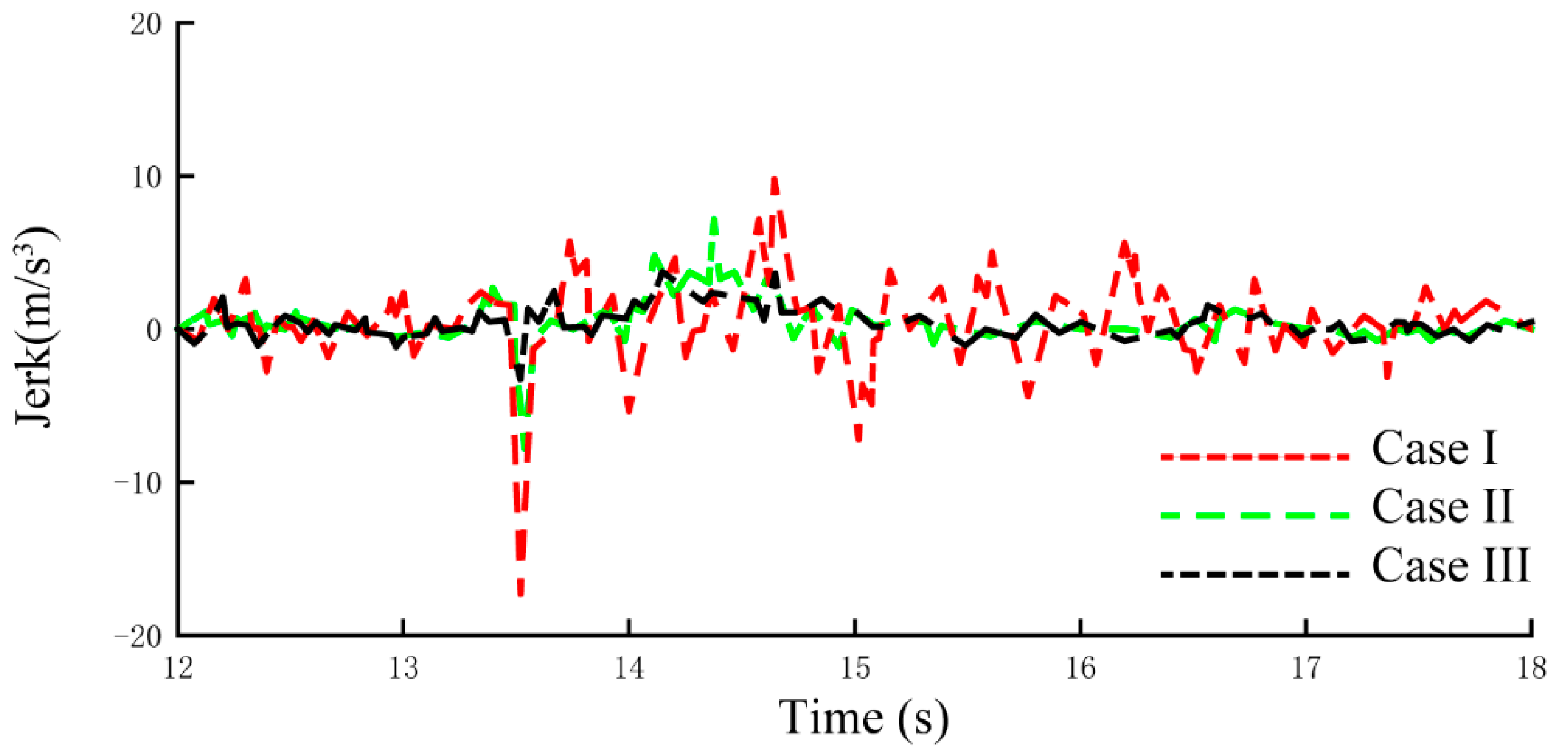
| Cases | Control Strategy |
|---|---|
| I | Without coordinated control |
| II | Motor control with SMC |
| III | Motor control with GP-SMC and engine control with Fuzzy-PI |
| Control Strategy | Clutch Frictional Loss (kJ) | Maximum Vehicle Jerk (m/s3) | Maximum Vehicle Velocity Error (%) |
|---|---|---|---|
| Case I | 6.074 | 18.81 | 7.37 |
| Case II | 4.983 | 8.65 | 3.95 |
| Case III | 1.897 | 4.03 | 1.27 |
Publisher’s Note: MDPI stays neutral with regard to jurisdictional claims in published maps and institutional affiliations. |
© 2022 by the authors. Licensee MDPI, Basel, Switzerland. This article is an open access article distributed under the terms and conditions of the Creative Commons Attribution (CC BY) license (https://creativecommons.org/licenses/by/4.0/).
Share and Cite
Xu, S.; Tian, X.; Wang, C.; Qin, Y.; Lin, X.; Zhu, J.; Sun, X.; Huang, T. A Novel Coordinated Control Strategy for Parallel Hybrid Electric Vehicles during Clutch Slipping Process. Appl. Sci. 2022, 12, 8317. https://doi.org/10.3390/app12168317
Xu S, Tian X, Wang C, Qin Y, Lin X, Zhu J, Sun X, Huang T. A Novel Coordinated Control Strategy for Parallel Hybrid Electric Vehicles during Clutch Slipping Process. Applied Sciences. 2022; 12(16):8317. https://doi.org/10.3390/app12168317
Chicago/Turabian StyleXu, Shanzhen, Xiang Tian, Cheng Wang, Youning Qin, Xiaohu Lin, Jingxuan Zhu, Xiaodong Sun, and Tiandong Huang. 2022. "A Novel Coordinated Control Strategy for Parallel Hybrid Electric Vehicles during Clutch Slipping Process" Applied Sciences 12, no. 16: 8317. https://doi.org/10.3390/app12168317