Article

Influence of Internal Flow on the Performance of High-Speed Centrifugal Pumps with a Fully Sealed Structure

1
School of Energy and Power Engineering, Xi’an Jiaotong University, Xi’an 710049, China
2
Aerospace System Engineering Shanghai, Shanghai 201109, China
*
Author to whom correspondence should be addressed.
Appl. Sci. 2022, 12(10), 5263; https://doi.org/10.3390/app12105263
Submission received: 2 May 2022 / Revised: 18 May 2022 / Accepted: 21 May 2022 / Published: 23 May 2022

Abstract

:
A high-speed centrifugal pump with a fully sealed structure has the advantages of a small size, no external leakage, and being pollution-free. The inner leakage passage of a pump with a fully sealed structure includes the tip clearance and the hub clearance. The hub clearance, the lubrication passage of the bearing, and the clearance between the stator and the rotor of the built-in motor constitute the internal flow channel. As a consequence of hub leakage, the complexity of the flow field increases and performance of the pump is affected. However, hub leakage also lubricates the bearing and cools the motor by flowing through the internal flow channel. To obtain the actual flow field distribution and external characteristics of the pump, a coupling calculation based on a conventional CFX simulation and MATLAB was carried out. The results show that hub leakage promotes an increase in tip leakage and changes the distribution of the main flow field. Moreover, hub leakage also significantly affects the efficiency of the pump. Compared with hub leakage, the internal flow has a greater impact on the performance of the pump. The numerical simulation results of the internal flow model are similar to the experimental results, with the maximum absolute error of the head at 0.3 m and the maximum absolute error of the efficiency at 1.7%, indicating that the internal flow model is effective at predicting the performance of the high-speed centrifugal pump with a fully sealed structure.

1. Introduction

A high-speed centrifugal pump with a fully sealed structure has the advantages of being small, free of external leakage, and free of any rolling bearings and fans so that it does not need lubricating oil and has no pollution. The inner leakage passage of a pump with a fully sealed structure includes the tip clearance and the hub clearance. The hub clearance, the lubrication passage of the bearing, and the clearance between the stator and the rotor of the built-in motor constitute the internal flow channel. Hub leakage flows through the internal flow channel as the internal flow to lubricate the sliding bearing and cool the motor. This not only solves the problems of cooling the motor and preventing sliding bearing failures caused by friction and the accumulated heat in the lubricant fluid, but also effectively increases the upper speed limit, improving the working performance of the pump [1,2]. Moreover, due to the changes in the liquid film and displacement of the sliding bearing in the working process, the leakage channel is dynamic [3]. The internal flow increases the tip leakage and complicates the flow field, which generally affect the performance of the pump.
Many achievements have been made in the numerical simulation of pump characteristics. Hamed et al. [4] conducted an unsteady numerical simulation and a performance test of a centrifugal pump and analyzed the development of the tip leakage vortex and the principles affecting the performance of the pump. Through numerical simulation research, Benjamin W. et al. [5] found that the tip leakage channel accounted for a relatively small proportion compared with the mainstream area, but the impact of tip leakage on the pump performance could not be ignored. Additionally, the increase in the impeller tip clearance caused additional losses. Through visual experiments, Michael M. found that increasing the tip clearance will reduce the pump performance [6]. Through numerical simulation research, Baoling et al. [7] found that the leakage vortex formed by tip leakage is an important factor interfering with the internal flow of the impeller. Georgios M. et al. verified though visual experiments the findings of a numerical simulation study (tip leakage affects the pump performance by destroying the flow field and the degree of influence is related to the tip clearance thickness) [8]. Through numerical simulation and experimental research, Yabin L. found that tip leakage will promote the development of a leakage vortex and the separation of the vortex, based on which they proposed a power function law to describe the intensity of the primary tip leakage vortex core along the trajectory [9,10,11]. Jingling L. et al. [12,13] performed a numerical simulation of the entire passage of a centrifugal pump and analyzed the frequency spectrum characteristics, the external characteristics of the tip leakage vortex, and the structural characteristics and their influence on the pump. Through a numerical simulation, Beomjun K. et al. found that the existence of tip leakage and hub leakage caused a loss of flow and promoted the growth of a vortex in the pump [14]. Dazhuan W. et al. [15] numerically simulated the three-dimensional flow field of a centrifugal pump considering tip leakage and hub leakage and put forward structural design suggestions by comparing the influence of structural parameters on the performance of the centrifugal pump. According to the above analysis, the internal leakage in the centrifugal pump affects the pump performance by interfering with the flow field distribution. The numerical simulation of centrifugal pump performance in the above-mentioned studies was used to analyze the influence of internal leakage on the performance of the pump. Most of the studies only considered tip leakage and a few considered hub leakage. However, all of them ignored the influence of the internal flow in the bearing lubrication and motor cooling channel. To obtain a higher-precision simulation of the flow in a centrifugal pump with a fully sealed structure, a model that fully considers the influence of the pump’s internal leakage needs to be researched.
In this paper, a CFX–MATLAB coupling calculation was performed to simulate the flow field of the pump and analyze the influence of internal flow on the flow field distribution. The simulation results were compared with the experimental results to verify the accuracy of the internal flow model and the calculation method.

2. Model and Methods

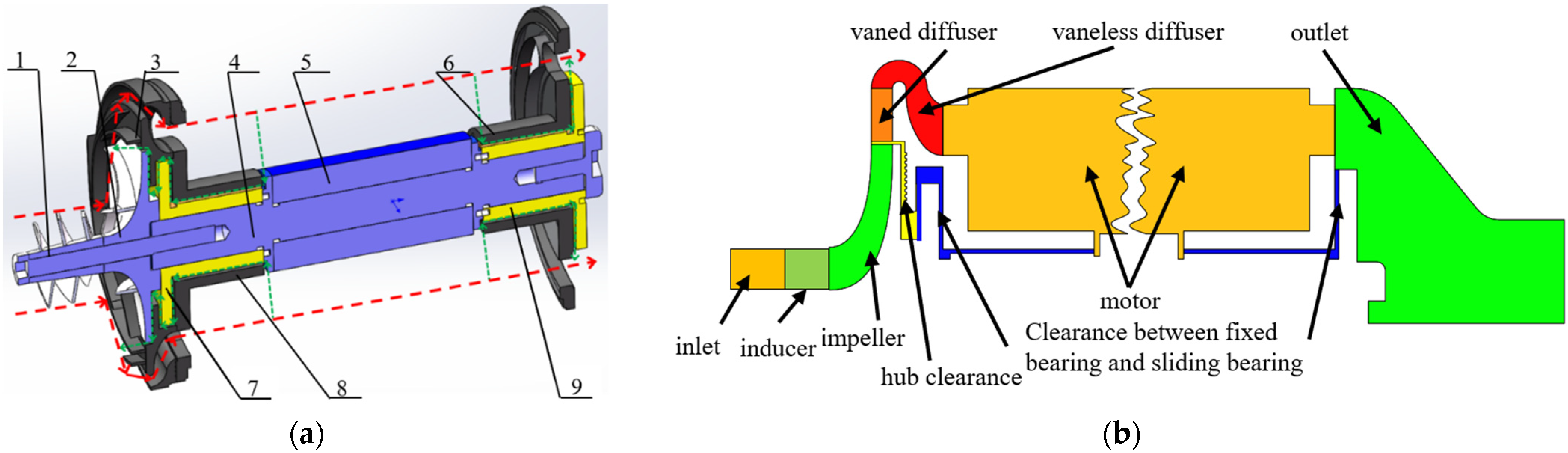
2.1. Structural Parameters of the Pump

A Xi’an Jiaotong University doctoral student named Xufeng F. [16] developed a new type of high-speed centrifugal pump with a sealed structure. The design parameters of the centrifugal pump are a flow rate Q = 3 m3·h−1, a head H = 30 m, and a rotational speed n = 7500 rpm. Different from other pumps, sliding bearings are adopted in the pump instead of ball bearings. The structural parameters of the pump are listed in Table 1, and images of the pump are shown in Figure 1.

2.2. Physical Model

A model diagram and a flow passage diagram of the low-specific-speed high-speed centrifugal pump with a fully sealed structure are shown in Figure 2. The model is composed of an inlet section, an inducer, an impeller, a vaned diffuser, a vaneless diffuser, a motor flow channel, an outlet section, and an internal flow channel. The internal leakage channel is divided into two sections. The first section is the hub and head bearing channel, which is composed of the hub clearance, the clearance between the head fixed bearing and the head sliding bearing, and the connecting parts, as indicated by the part highlighted in yellow and blue on the left side of Figure 2b. The other section is the tail bearing channel, which is composed of the clearance between the tail fixed bearing and the tail sliding bearing and the connecting parts, as indicated by the part highlighted in blue on the right side of Figure 2b.

2.3. Mesh Independence Study

The inducer, impeller, and diffuser of the pump were meshed by TurboGrid. The inlet section, vaneless diffuser, motor flow channel, and outlet section were meshed by ICEM. The internal flow channel was meshed by gambit. To perform the mesh independence study, five groups of models with different grid numbers were simulated, taking the head of the pump as the target parameter. When the number of model grids was 0.54 M, 2.26 M, 4.24 M, 7.58 M, and 10.07 M, the pump head corresponding to the design flow condition was 26.98 m, 27.31 m, 27.50 m, 27.61 m, and 27.61 m, respectively. Therefore, the fourth group of grids was selected for subsequent research.

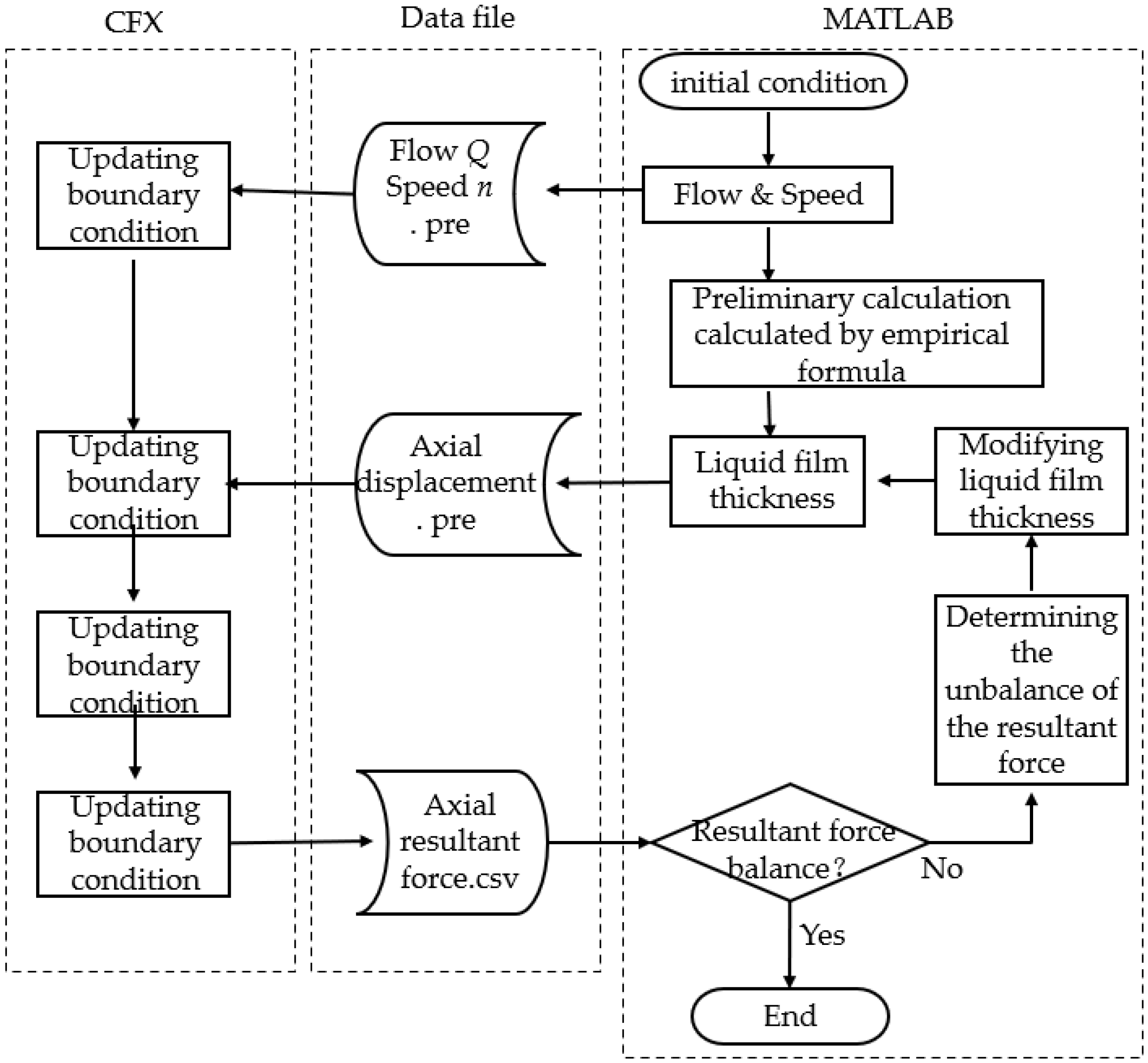
2.4. Calculation Method

During the operation of the high-speed centrifugal pump, the axial displacement of the rotor is 4 orders of magnitude different from the minimum scale of the centrifugal pump, so the influence of the axial displacement on the flow field can be ignored. Therefore, it is unnecessary to carry out a dynamic grid calculation considering the axial force balance. As for a pump with an internal flow channel, its rotor is floating during operation. When the working conditions change, both the balance position of the axial force and the bearing capacity change continuously, and the rotor moves back and forth in the axial direction. In addition, the liquid film thickness directly affects the flow field as well as the flow rate of the internal flow. Therefore, a MATLAB–CFX coupling calculation method was adopted.
The clearance of the high-speed centrifugal pump with a fully sealed structure is composed of four main parts, namely the front liquid film thickness, the tail liquid film thickness, the tip clearance, and the hub clearance. When the pump operates in a stable state, the axial resultant force is zero and the rotor is in the balance position. When the working condition changes, the distribution of the flow field at the inlet of the sliding bearing changes, and the axial force of the impeller becomes non-zero. Moreover, the change in the working condition will also cause the motor to move, which will affect the size of the tip clearance and the hub clearance in turn. As a result, the flow field distribution of the impeller will change again. A flow chart of the calculation is shown in Figure 3. The coupled steady-state calculation of the impeller and the bearing was simulated by MATLAB and the ANSYS-CFX platform. In MATLAB, the axial force of the impeller and the bearing capacity of the bearing are both calculated through the empirical formula, and an approximate liquid film thickness is given in advance. Then, CFX is called through the batch file to write the flow, speed, and axial displacement of the rotor into the intermediate data file. In CFX, according to the displacement given by the data file, the grid of the flow field is updated by using the moving grid method, and the information on the axial force is transmitted to MATLAB after the calculation converges. Next, in MATLAB, the liquid film thickness is modified again according to the imbalance in the axial force, after which CFX is called to perform a recalculation. The above-described steps repeat until the resultant force reaches equilibrium.
Since the working medium in the pump, which is water, is an incompressible fluid, governing equations of incompressible flow were adopted that ignore the change in temperature. The equations for the pump head and efficiency are shown below.
H = P out ρ g P in ρ g + z
η = P u P u + P h + P v + P m
where P out is the outlet pressure of the pump, P in is the inlet pressure of the pump, ρ is the density of water, g is a constant term, and z is the height difference between the outlet and the inlet. In Equation (2), P u is the useful power, P h is the hydraulic loss power, P v is the volume loss power of the internal flow and tip leakage, and P m is the mechanical loss power, which is mainly composed of the disc friction loss power.

3. Numerical Simulation Results

3.1. Impact of the Internal Flow on External Characteristics

To analyze the effect of internal flow on external characteristics of the pump, three calculation models with different internal leakage channels were built for numerical simulations, and the test-bed described in [10] was used for experiments under different flow conditions. As with all open and semi-open impeller high-speed centrifugal pumps, tip leakage is inevitable. The numerical simulation of a pump considering tip leakage can be carried out by using a model whose impeller contains a fixed tip clearance, so tip leakage is considered in most studies. Hub leakage refers to the flow of fluid into the hub clearance from the gap between the impeller outlet and the diffuser inlet. The sealing structure is set in the hub clearance, which can reduce hub leakage to a certain extent, resulting in the omission of hub leakage in most studies. However, the hub leakage in a pump with a sealed structure is comprised of both the internal leakage and the internal flow. It flows through the internal flow channel and rejoins the main stream, during which time it lubricates the sliding bearing and cools the motor. As a consequence of hub leakage, the flow field becomes more complicated and the performance of the pump is affected. Therefore, in pumps with a fully sealed structure, hub leakage cannot be ignored, and a model that considers the complete internal flow channel is required to accurately study the influence of hub leakage on the pump.
The first model, the tip leakage model, contains the main flow channel and the tip clearance, based on which the second model, the tip–hub leakage model, considers the hub leakage. The third model, the internal flow model, takes into account all flow channels, including the tip clearance channel and the internal flow channel. A comparison between the calculated results of each model and the experimental values is shown in Table 2. With the increase in the leakage channel, the following changes occur simultaneously: the tip leakage flow continues to increase, the pump head first increases and then decreases, and the efficiency shows a decreasing trend, which becomes increasingly similar to the experimental values. This variation is consistent with [17]. Between the tip leakage model and the tip–hub leakage model, the relative error of the head is 0.5% and the relative error of the efficiency is 10%, indicating that hub leakage greatly affects the efficiency. Between the tip–hub leakage model and the internal flow model, the relative error of the head is 2.9% and the relative error of the efficiency is 2.1%, indicating that the influence of leakage from the bearing clearance on the external characteristics of the pump cannot be ignored. Between the tip leakage model and the internal flow model, the relative error of the head is 2.4% and the deviation in the efficiency is 12.1%. Moreover, compared with the tip leakage model, the tip leakage of the internal flow model increases by 52%, indicating that the internal flow greatly increases the tip leakage and significantly affects the external characteristics of the pump. Since the internal flow lubricates the bearing, cools the motor, and has a great impact on the external characteristics of the pump, the complete internal flow channel must be adopted in order to build a model of a centrifugal pump with a fully sealed structure.

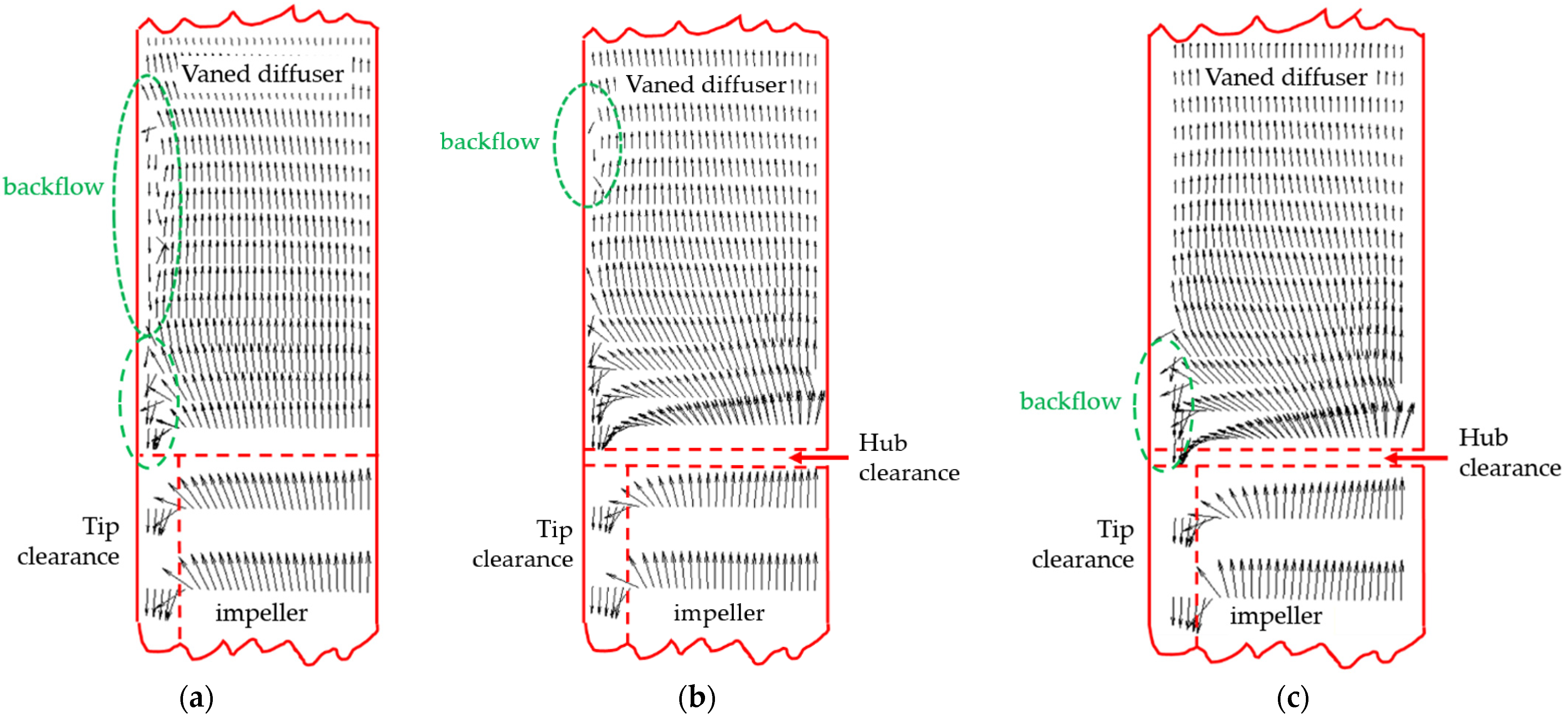
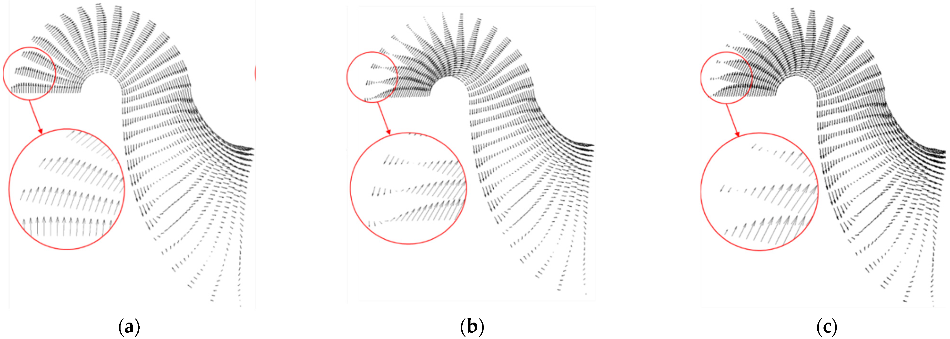
3.2. Impact of the Internal Flow on the Flow Field

A meridional velocity vector diagram of the impeller and the diffuser under design conditions is shown in Figure 4. When the influence of internal leakage is not considered, the main stream basically contains only the velocity vector along the flow direction. As can be seen in Figure 4a, tip leakage disturbs the direction of the flow of the fluid that is on the top of hydraulic components, leading to the appearance of backflow in the middle on the top of the vaned diffuser. As can be seen in Figure 4b, the backflow generated in the hub clearance damages the uniform flow field, resulting in a rapid increase in tip leakage and the upward velocity vector component of the fluid near the interface between the impeller and the vaned diffuser. At the same time, the upward velocity vector component of the main flow in the vaned diffuser increases, shortening the length of the top backflow section caused by tip leakage. As can be seen in Figure 4c, compared with hub leakage, the internal flow has a greater impact on the flow field of the pump. The static pressure of the main stream increases rapidly after it passes through the diffuser, then the partial flow, namely the internal flow, flows back from the internal flow channel into the junction between the impeller and the vaned diffuser. As a consequence of the internal flow, both the upward velocity vector component of the fluid in the vaned diffuser and the tip leakage flow increase, and the flow disturbance exacerbates, resulting in the appearance of backflow. Generally, the existence of an internal flow complicates the flow field distribution in the impeller and the vaned diffuser, which further destroys the uniform flow field of the main stream. As a result, the tip leakage flow increases and both the position and degree of the backflow change.
To convert the fluid from a radial flow to an axial flow and reduce the fluid diffusion problem caused by the excessive cross-sectional area in the subsequent flow channel, the vaneless diffuser is designed to have a bend, as shown in Figure 5. In the vaneless diffuser, due to the change in the channel’s direction and the action of centripetal force, the velocity vector component of the fluid that points to the center of the curve increases. According to the law of flow at an elbow, the fluid at the top of the inlet of the vaneless diffuser diffuses while the fluid at the bottom shrinks. Moreover, there is a concave wall vortex zone at the top [18]. Such a flow field distribution is also affected by the flow field distribution of the former hydraulic component, which is the vaned diffuser. The longer the length of the backflow in the vaned diffuser, the smaller the disturbance at the top of the inlet of the vaneless diffuser. When there is some backflow at the top of the vaned diffuser, the upward velocity vector component of the nearby fluid is large, which cancels out the velocity vector component towards the center of the curve caused by the centripetal force so that the disturbance is reduced. The backflow and secondary flow at the outlet of the vaneless diffuser are mainly caused by the drastic change in the flowing cross-sectional area at the interface between the outlet and the motor flow channel. In conclusion, the internal flow further affects the flow field distribution in the vaneless diffuser by affecting the flow field of the vaned diffuser.
A diagram of the stream line of the motor flow channel and the outlet flow channel is shown in Figure 6. In the motor flow channel, the fluid is divided into two streams due to the existence of the motor stator. A stream flows along the outer wall of the stator and the pump housing. There are some vortices that appear at the head of the flow channel due to the disturbance caused by the structural change in the inlet, and the subsequent stream line gradually becomes uniform. The other stream flows along the gap between the shaft wall and the inner wall of the stator. Due to the disturbance of the shaft wall and the bearing channel, the stream line in the channel is always in a fluctuating state, and eddy currents of varying degrees appear in the middle section. With the increase in the flow, the vortex moves backward, and the number of vortices decreases. In the meantime, the area of the single vortex expands.

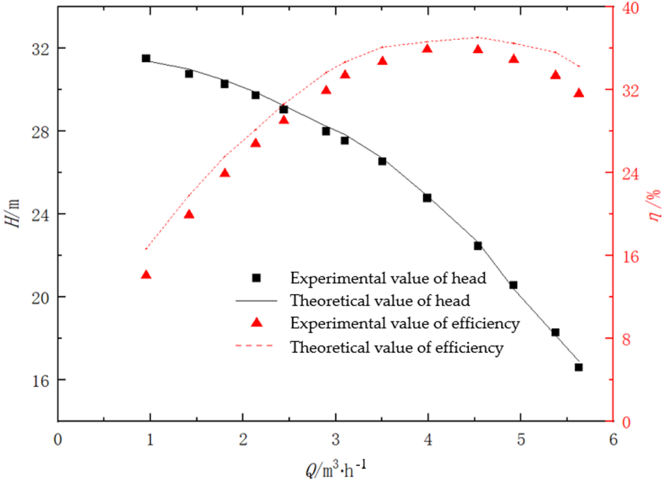
3.3. Comparison between Numerical Simulation Results and Experimental Results

A comparison of the experimental results and simulation results under different flow conditions is shown in Figure 7. It can be seen that the results of the internal flow model are very close to the experimental values, with the maximum absolute error of the head at 0.3 m and the maximum absolute error of the efficiency at 1.7%. Since some mechanical losses were ignored in the simulation calculation, the overall predicted value for efficiency is larger than the experimental value.
Generally, based on the CFX–MATLAB coupling calculation method, the prediction performance of the internal flow model is sufficiently accurate and reliable for high-speed centrifugal pumps with a fully sealed structure. Hence, the proposed method is of qualitative and even quantitative significance to the numerical simulation of centrifugal pumps with a fully sealed structure.

4. Conclusions

Three models of the centrifugal pump with a fully sealed structure referred to in [10] were established, and a CFX–MATLAB coupling calculation method was proposed to analyze them. Through a comparison of numerical simulation results and experimental results, the following conclusions were drawn.
1.
Hub leakage destroys the uniform flow field of the main stream and significantly affects the pump’s efficiency. Hub leakage promotes an increase in the tip leakage flow and the upward velocity vector component of the main stream, which affects the distribution of the main stream field.
2.
Compared with hub leakage, the internal flow further destroys the uniform flow field of the main flow and has a great impact on the performance of the pump. Between the tip leakage model and the internal flow model, the relative error of the head is 2.4% and the relative error of the efficiency is 12.1%.
3.
Under the design conditions, the external characteristics of the internal flow model are the closest to the experimental results, with the absolute error of the head at 0.03 m and the absolute error of the efficiency at 1.3%.
4.
In the actual flow in the pump, the axial displacement of the main shaft leads to a change in the front liquid film thickness, the tail liquid film thickness, the tip clearance, and the hub clearance, as a result of which the flow field is dynamic. Based on the CFX–MATLAB coupling calculation method, the internal flow model can better simulate the flow in a pump with a dynamic flow field and predict the performance of a pump with a fully sealed structure. Under different flow conditions, the simulation results were found to be very close to the experimental results, with the maximum absolute error of the head at 0.3 m and the maximum absolute error of the efficiency at 1.7%.

Author Contributions

Investigation, X.L.; data curation and paper writing, X.L. and B.Z.; numerical study, B.Z.; experiment system design, L.C. and T.L.; data analysis, M.Z. and Y.Z.; supervision and project administration, R.X. All authors have read and agreed to the published version of the manuscript.

Funding

This research was funded by the National Natural Science Foundation of China grant number 51976150, the Fundamental Research Funds for the Central Universities, and the Youth Innovation Team of Shaanxi Universities.

Institutional Review Board Statement

Not applicable.

Informed Consent Statement

Not applicable.

Data Availability Statement

Not applicable.

Conflicts of Interest

The authors declare no conflict of interest.

References

  1. Gerasimov, V.S.; Nikiforov, S.A.; Pautov, Y.M.; Snetkov, V.G.; Fedorov, G.P.; Mikhailov, A.D. Development of high-load water-lubricated radial-axial bearings for electric-pump units in the first loop of a nuclear power plant. At. Energy 2000, 89, 1027–1030. [Google Scholar] [CrossRef]
  2. Xue, R.; Cai, Y.; Fang, X.; Chen, L.; Zhang, X.; Hou, Y. Optimization study on a novel high-speed oil-free centrifugal water pump with hydrodynamic bearings. Appl. Sci. 2019, 9, 3050. [Google Scholar] [CrossRef] [Green Version]
  3. Fang, X.; Hou, Y.; Cai, Y.; Chen, L.; Lai, T.; Chen, S. Study on a high-speed oil-free pump with fluid hydrodynamic lubrication. Adv. Mech. Eng. 2020, 12, 1–14. [Google Scholar] [CrossRef]
  4. Hamed, A.; Seyyed, A.N.; Mehrdad, R.; Amir, F.N. Effect of the volute tongue profile on the performance of a low specific speed centrifugal pump. Proc. Inst. Mech. Eng. Part A J. Power Energy 2014, 229, 210–220. [Google Scholar]
  5. Benjamin, W.; Robert, K.; Philipp, S.; Peter, J.; Caitlin, S. Numerical and experimental investigation of an impeller tip clearance variation in an aero-engine centrifugal compressor with close-coupled pipe-diffuser. CEAS Aeronaut. J. 2014, 5, 171–183. [Google Scholar]
  6. Michael, M.; Bernd, W.; Dominique, T. Effect of tip clearance gap and inducer on the transport of two-phase air-water flows by centrifugal pumps. Exp. Therm. Fluid Sci. 2018, 99, 487–509. [Google Scholar]
  7. Baoling, C.; Desheng, C.; Canfei, W.; Zuchao, Z.; Yingzi, J.; Yuzhen, J. Research on performance of centrifugal pump with different-type open impeller. J. Therm. Sci. 2013, 22, 586–591. [Google Scholar]
  8. Georgios, M.; Ioannis, K.; George, A.; Ioannis, A. Numerical simulation of the performance of a centrifugal pump with a semi-open impeller under normal and cavitating conditions. Appl. Math. Model. 2021, 89, 1814–1834. [Google Scholar]
  9. Yabin, L.; Lei, T.; Hao, Y.; Xu, Y. Energy performance and flow patterns of a mixed flow pump with different tip clearance sizes. Energies 2017, 10, 191. [Google Scholar] [CrossRef]
  10. Yabin, L.; Lei, T. Tip clearance on pressure fluctuation intensity and vortex characteristic of a mixed flow pump as turbine at pump mode. Renew. Energy 2018, 129, 606–615. [Google Scholar]
  11. Yabin, L.; Lei, T. Spatial-temporal evolution of tip leakage vortex in a mixed flow pump with tip clearance. J. Fluids Eng. 2019, 141, 081302. [Google Scholar]
  12. Jinling, L.; Lei, G.; Like, W.; Wei, W.; Pengcheng, G.; Xingqi, L. Unsteady flow characteristics of tip clearance in semi-open impeller centrifugal pump. Trans. Chin. Soc. Agric. Mach. 2019, 50, 163–172. [Google Scholar]
  13. Like, W.; Jinling, L.; Weili, L.; Yaping, Z.; Wei, W. Numerical simulation of the tip leakage vortex characteristics in a semi-open centrifugal pump. Appl. Sci. 2019, 9, 5244. [Google Scholar] [CrossRef] [Green Version]
  14. Beomjun, K.; Keuntae, P.; Haecheon, C.; Myungsung, L.; Joo-Han, K. Flow characteristics in a volute-type centrifugal pump using large eddy simulation. Int. J. Heat Fluid Flow 2018, 72, 52–60. [Google Scholar]
  15. Dazhuan, W.; Youbo, S.; Tao, C.; Binjie, X.; Leqin, W. Numerical study on key parameters optimization of semi-unshrouded impeller. J. Eng. Thermophys. 2013, 34, 75–78. [Google Scholar]
  16. Xufeng, F.; Yijie, C.; Xin, C.; Shuangtao, C.; Rong, X.; Liang, C.; Yu, H. Variable speed performance study of oil-free lubricated high-speed centrifugal pump. Fluid Mach. 2020, 48, 6–11. [Google Scholar]
  17. Chuan, W.; Weidong, S.; Xikun, W.; Xiaoping, J.; Yang, Y.; Wei, L.; Ling, Z. Optimal design of multistage centrifugal pump based on the combined energy loss model and computational fluid dynamics. Appl. Energy 2017, 187, 10–26. [Google Scholar]
  18. Yijun, Z.; Yiying, H. Hydraulic characteristics of Z-type pipe combination with two similar rectangular bends. J. Hydraul. Eng. 2006, 7, 778–783. [Google Scholar]
Figure 1. (a) The components of the pump; (b) the assembled pump.
Applsci 12 05263 g001
Figure 2. Diagram of the centrifugal pump with a fully sealed structure. (a) Model diagram of the pump (1, Inducer; 2, Impeller; 3, Diffuser; 4, Main axle; 5, Motor stator; 6, Tail end fixed bearing; 7, Front sliding bearing; 8, Front fixed bearing; 9, Tail end sliding bearing); and (b) flow passage diagram of the pump.
Applsci 12 05263 g002
Figure 3. Coupled steady-state calculation of the impeller and the bearing of the high-speed centrifugal pump.
Applsci 12 05263 g003
Figure 4. Velocity vector diagram of the meridional surface of the impeller and the vaned diffuser. (a) Tip leakage model; (b) tip–hub leakage model; (c) internal flow model.
Applsci 12 05263 g004
Figure 5. Velocity vector diagram of the meridional surface of the vaneless diffuser. (a) Tip leakage model; (b) tip–hub leakage model; (c) internal flow model.
Applsci 12 05263 g005
Figure 6. Stream line distribution of the internal flow passage of the motor and the outlet under different flow rates. (a) Stream line distribution at Q = 1 m3·h−1; (b) stream line distribution at Q = 3 m3·h−1; (c) stream line distribution at Q = 5 m3·h−1.
Applsci 12 05263 g006
Figure 7. Comparison between numerical simulation results and experimental data.
Applsci 12 05263 g007
Table 1. Structural parameters of the pump.
ParametersSymbolValue
Semi-open impellerNumber of bladesZ16
Inlet diameter (mm)D127.2
Outlet diameter (mm)D264.0
Outlet blade width (mm)b23.8
Outlet angle (°)β220
Vaned diffuserNumber of bladesZ27
Inlet diameter (mm)D365.0
Outlet diameter (mm)D482.0
Outlet angle (°)β35.8
Sliding bearingBearing radius (mm)Ro12.5
Inner circle radius (mm)Ri8
Number of groovesZ312
Groove width (mm)D83.54
Film thickness (μm)Hg3.3
Table 2. Comparison of the results of different models.
Head/mHead Relative Error (%)Efficiency (%)Tip Leakage Flow Relative Error (%)Tip Leakage Flow (kg·m−3)
Tip leakage model28.282.538.516.00.0795
Tip–hub leakage model28.423.035.26.00.1003
Internal flow model27.610.134.53.90.1209
Experimental values27.58 33.2
Publisher’s Note: MDPI stays neutral with regard to jurisdictional claims in published maps and institutional affiliations.

