1. Introduction
Microwaves are a form of electromagnetic radiation with wave frequencies (wavelengths) ranging from 300 MHz (
λ = 1 m) up to 300 GHz (
λ = 1 mm) [
1]. Microwave technology is nowadays present in numerous fields and is utilized in the radar and communication industry [
2], in laboratory measurements [
3], in medical and scientific appliances [
4], and in the field of chemistry [
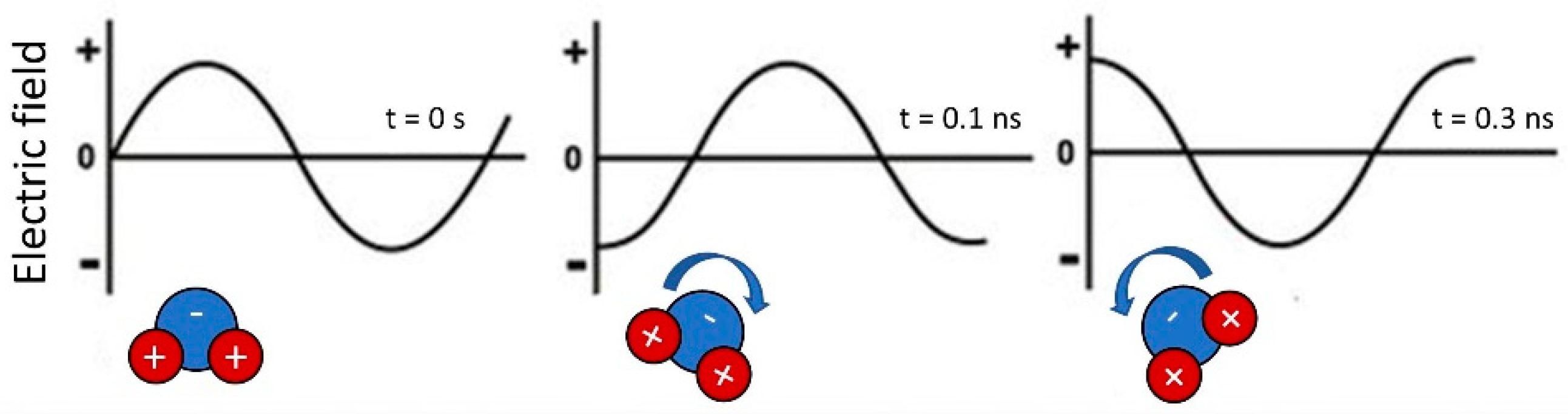
5]. This article focuses on issues related to the use of microwaves as an alternative method for heating and drying. Microwaves in this case are converted into heat by interacting with dielectric dipolar materials.
The most common substance that can easily absorb microwave energy and can dissipate it as heat is water [
6] as it is presented in
Figure 1. Additionally, some carbon-based materials react like dielectric materials, as they contain freely moving delocalized π-electrons [
7,
8,
9,
10].
In general, microwaves enable selective heating, rapid and high efficiency heat transfer, and device miniaturization, while decreasing the cost of energy used and environment pollution [
12].
Microwave heating is widely used in the areas of material science [
13,
14], analytical chemistry [
15], food processing [
16,
17], processing of materials [
18], metal fractionation in sewage sludge [
19], organic synthesis [
20], polymer synthesis [
21,
22], hospital waste sterilization [
23], and wood drying [
24].
Microwave heaters are excited through the use of a magnetron that produces fixed frequency oscillations. The microwaves are then guided to a microwave resonance chamber, where standing waves occur, increasing wave amplitude. Alternatively, microwaves can be applied to non-resonant cavities; in this case, high RF energy absorption occurs where no standing wave is generated. In both cases, however, the delivered energy is generated in the magnetron.
Designing a device especially equipped with a resonant chamber requires complex calculations based on field theory [
25]. Building and testing prototypes is time consuming and highly ineffective. An alternative to physical models is computational modelling, which uses the finite element method for solving differential equations describing a specific physical phenomenon [
26,
27].
A key factor in accurate FEM calculations is mesh density [
28,
29,
30]. Although Elmer FEM enables the use of second-order elements, the microwave ElmerSolver works only on tetrahedrons, so the shape of the elements used in the experiment is not discussed. The size of the involved elements has a great influence on the quality of the model. Small tetrahedral elements allow for more reliable solid representation and more accurate results. However, they are affected by a radical increase in calculation cost and memory resources. Moreover, this causes an unacceptably long time to be required to reach convergence on a solution. Furthermore, increasing mesh granularity makes the simulation more sensitive to numerical errors, such that it requires the more precise parameters of reality, which are sometimes difficult to get. Therefore, a compromise between mesh granularity, which is directly connected with calculation accuracy, and time consumption must be found.
The aim of this paper is to examine the influence of mesh granularity on the accuracy of FEM modelling of the resonant state in a microwave resonant chamber. The most commonly used chambers are rectangular and cylindrical chambers. The chamber could have any shape, but rectangular and cylindrical are most frequently used; hence, the authors decided to model a cylindrical chamber. The modelling was carried out utilizing ELMER FEM open-source software enabling FEM-based modelling of microwave resonant states [
31,
32]. The following section provides a detailed description of the chamber’s geometric design process.
2. Microwave Chamber’s Geometry
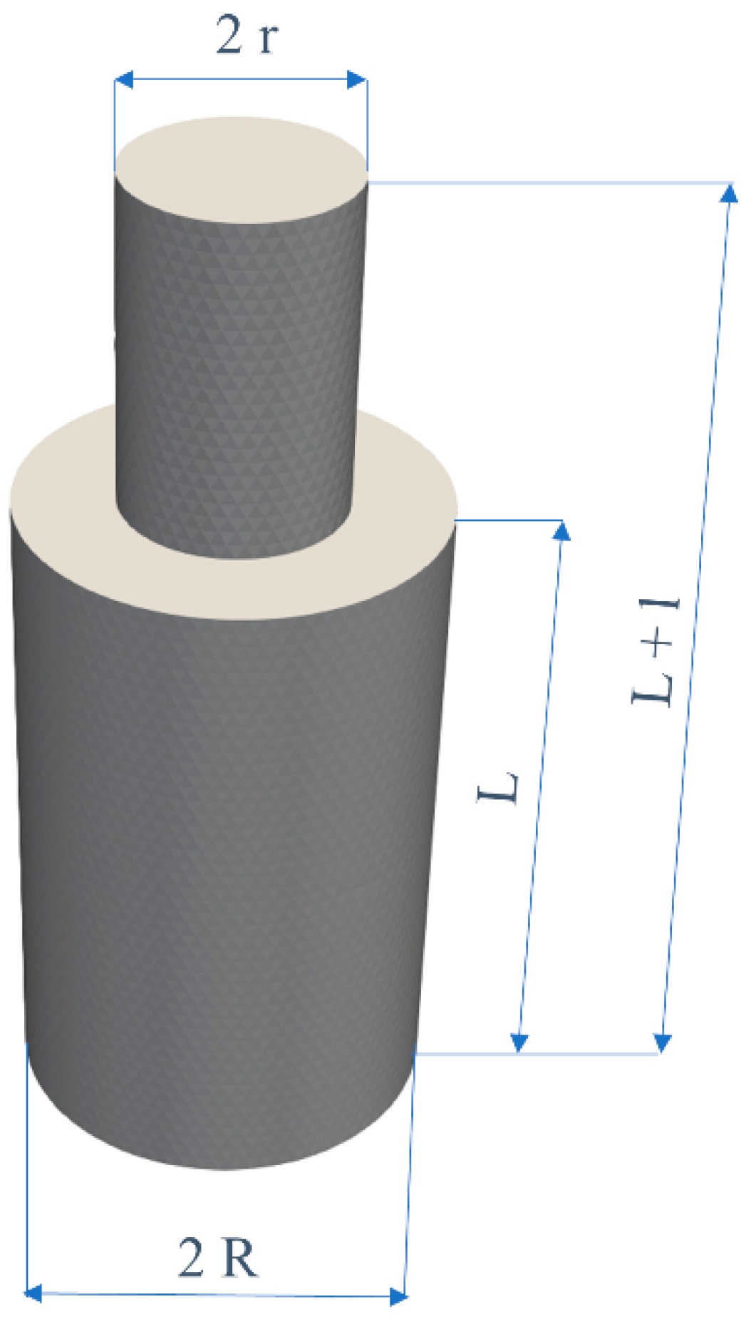
For the purpose of the experiment, a model of an exemplary cavity was developed: a cylindrical chamber with a cylindrical waveguide joined at the top of a chamber, as is displayed in
Figure 2. The model is described with four basic dimensions: the waveguide radius,
r; the waveguide’s length,
l; the chamber’s radius,
R; and the chamber’s length,
L.
It was assumed that the device would operate in a resonant frequency of 2.45 GHz, as the most commonly used microwave range in ovens operates at frequencies of about 2.45 GHz [
33]. Resonant frequency and field distribution shape is dependent on wave type and chamber dimensions and is related to the possibility of standing wave generation. The resonant frequency
fnmp of the cylindrical chamber for the transverse electric (TE) mode, where the electric field is transverse to the
Z axis [
34], is described as [
35]:
where
p’mn is the
n-th root of derivative of
m-th order Bessel function,
p is an axial mode number,
R is chamber’s radius and
L is the chamber length.
The chamber length L, as well as the waveguide length l, was an integer multiple of the wavelength λ: .
The waveguide radius,
r, was estimated using an equation describing cut-off angular frequency
ωc and phase constant
β [
36]:
where
p′mn is the
n-th root of derivative of
m-th order Bessel function,
r is the waveguide radius and
ω = 2
πf is the chamber’s angular resonant frequency. The condition used for deriving the waveguide radius is defined by a phase constant (3), which must be a positive value. Fulfilling the condition (3) guarantees lossless wave propagation. The biggest waveguide radius
r fulfilling the condition (3) was selected as
. Using Equation (1), the chamber radius
R can be calculated as
.
In order to generate multiple wave modes, the length L and the radius R of the chamber should be an integer multiple of the previously calculated dimensions: and .
On the base of Equations (1)–(3), the resonance should occur for the chamber radius R equal to 151 mm. However, it should be highlighted that the analytical model given by Equations (1)–(3) enables only a rough estimation of the size of the microwave resonant chamber. Moreover, this estimation is possible only for a simple shape of such a chamber, whereas for technical purposes, much more sophisticated shapes are often required. As a result, the dimensions of the microwave chamber necessary for the resonance can be estimated only on the basis of the FEM model. Moreover, achieved results can be verified only experimentally, after the manufacturing of the chamber.
Estimations made for device dimensions and dimensional tolerances based on finite elements modelling significantly reduces the cost of development and practical validation of the operability of microwave resonant chambers for industrial applications. In addition, even in simplified cases, the achieved results significantly vary from the results of Equations (1)–(3). These differences are caused by, e.g., the significant size of the microwave waveguide and strongly influence the operation of real devices. In the next section, the technical method of validation of the FEM mesh granularity value is proposed, which can be used for any shape of microwave resonant chamber.
3. Implementation of Proposed Models in Open-Source FEM-Oriented Software
In the microwave field, there are a few specialized programs that provide FEM solutions for models. However, development tool chains are usually highly expensive, which can be an obstacle for researchers and smaller companies to utilize them. The alternative is open-source software, which also has the benefit of freely available code for calculation verification purposes. Implementation of the proposed model was carried out exclusively with the use of an open-source microwave modelling tool chain, operated under LINUX MINT [
37], covering OCTAVE (free equivalent of MATLAB) [
38], NETGEN mesh generator [
39,
40,
41], ELMER FEM microwave FEM solver [
42] and PARAVIEW [
43,
44] software for visualization of results.
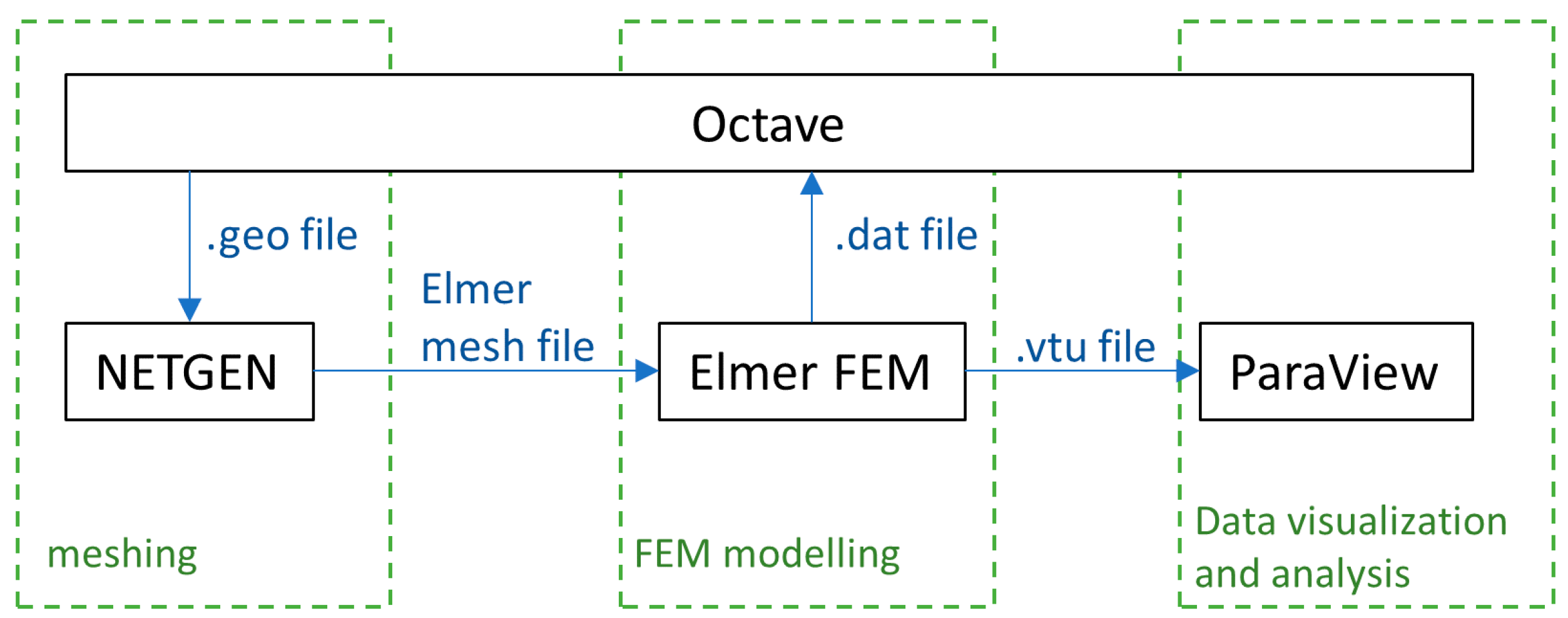
The tool chain block diagram is presented in
Figure 3. The whole process was controlled by scripts in Octave, which generated a series of NETGEN batch .geo files describing the geometry of the model. NETGEN discredited the model with the Delaunay triangulation algorithm [
45] and converted the mesh into ELMER mesh files. ELMER FEM software was used for solving Maxwell equations and introducing the module for wave equations [
46]. After each model computation, the results were saved both into Octave (.mat) and PARAVIEW (.vtu) format for further analysis.
The software was used under a GNU GPL license; thus, the cost of possible commercialization will not be a barrier to the use of the results presented in this paper.
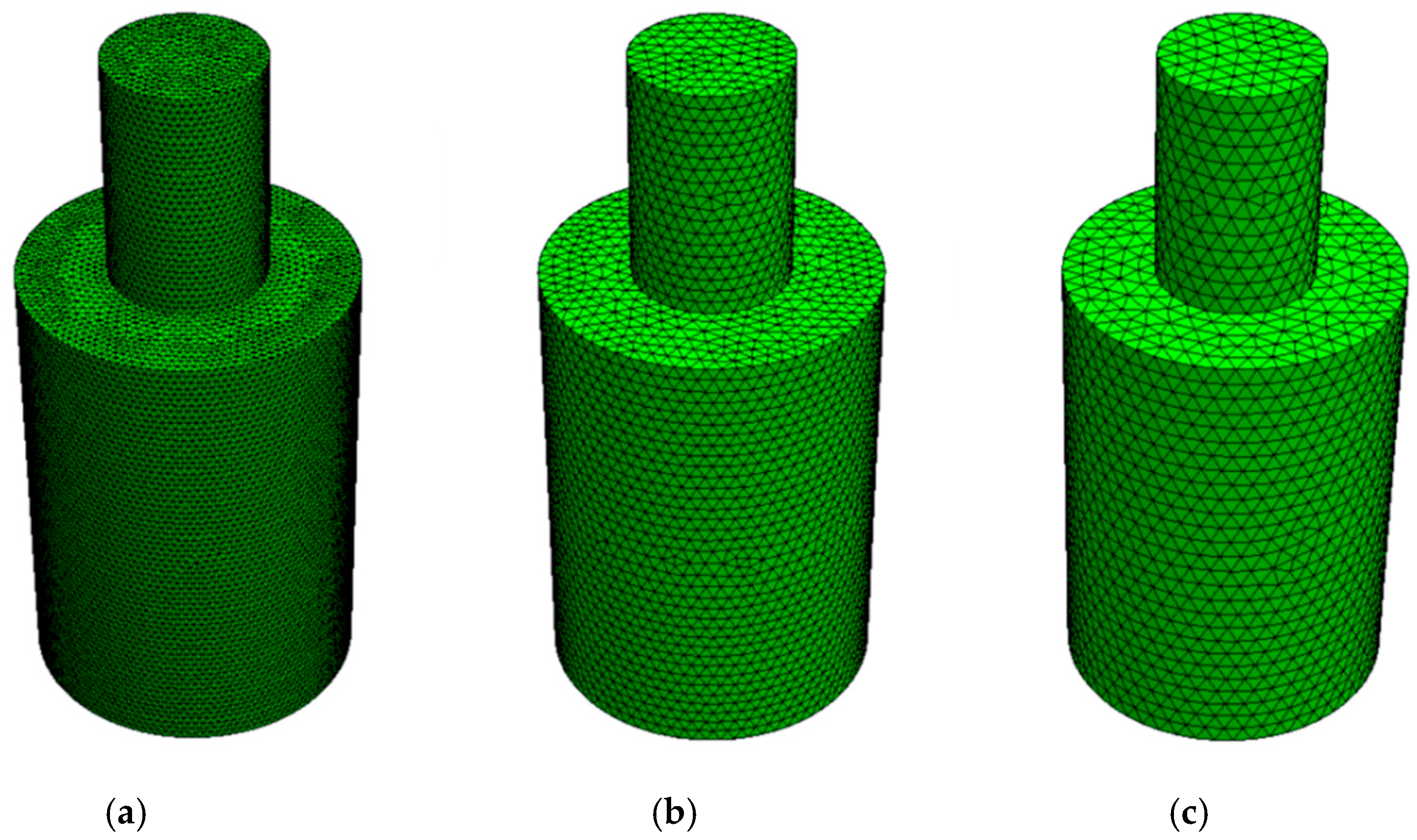
In the case of tetrahedral meshes generated during the Delaunay triangulation process being implemented in NETGEN, the mesh granularity is determined by the maximal height of tetrahedral element
hmax. In order to check mesh influence on the resonant state, a number of simulations were carried out prior to the commencement of the planned experiment. The first series made it possible to find the radius for which there is the strongest resonance (as mentioned in the previous section; as a result of the calculations we only get an approximate value). It was identified that the best resonance occurs for
R = 171 mm. In the next series of calculations, a series of models with radius ranging from 168–174 mm in intervals of 1 mm and for five mesh granularities with the maximum element height of the mesh (
hmax) set to 8, 10, 12, 15, 20 mm, respectively, was carried out. Only the results for the coarsest mesh (for
hmax = 20 mm) show a different extreme field strength for the model with 170 mm radius, whereas for all of the others, the best resonance parameters were gained for a chamber of 171 mm radius. The obtained results were used in the main part of the experiment. Finally, seven models of radiuses
R range from 169.25–171.75 mm with an interval of 0.25 mm were implemented. The maximum element height of the mesh (
hmax) was the same as in the preliminary experiment: 8, 10, 12, 15, and 20 mm, which gave 35 models in total. The specific range of radiuses
R depended on the maximum element height for the mesh:
R was in the range of 169.25–171.75 mm for
hmax equal to 20 mm and R was in the range of 170.25–171.25 mm for all the other
hmax values, which were equal to 8, 10, 12, 15 mm. The example of meshes used for modelling is given in
Figure 4.
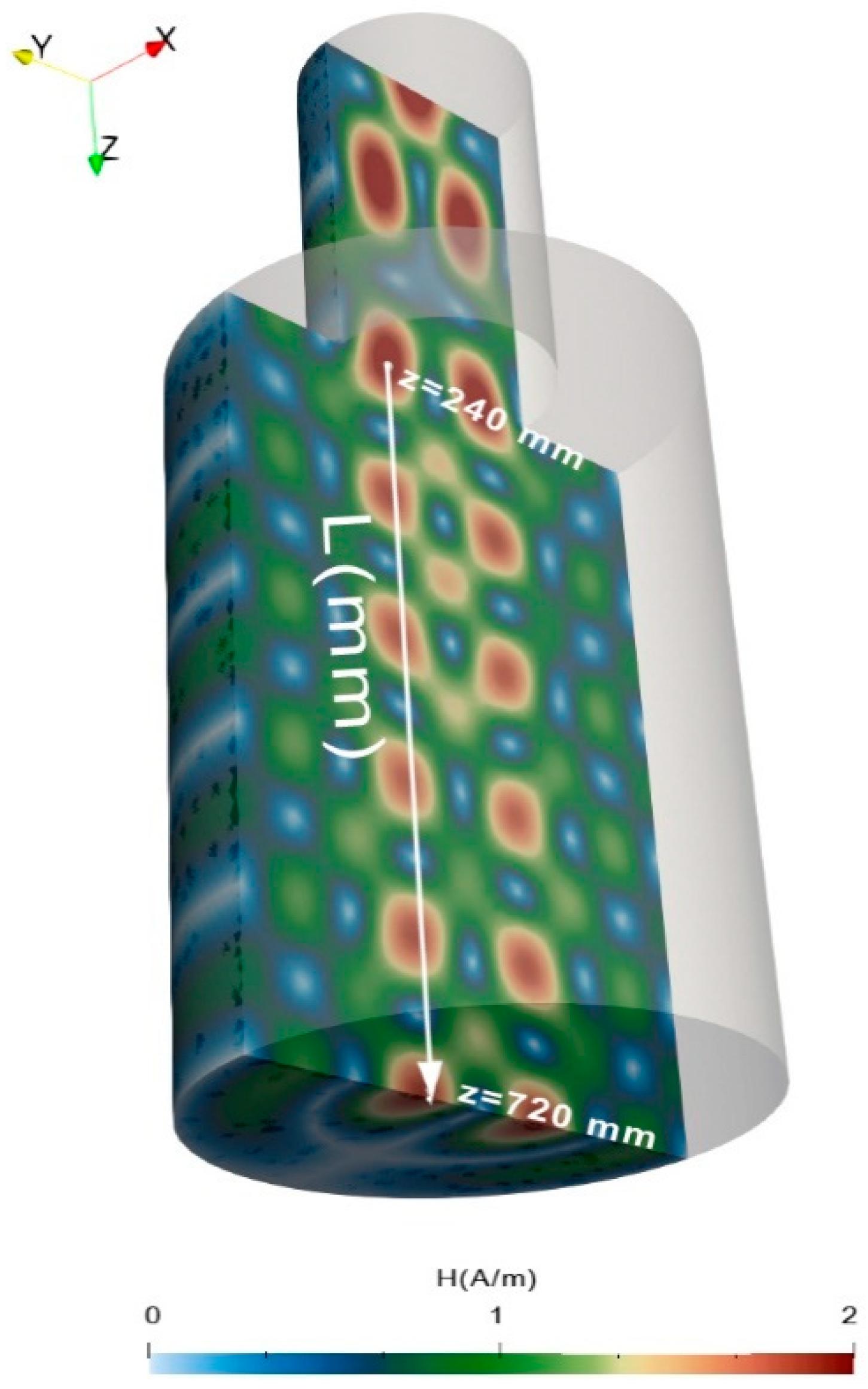
To perform the analysis, the electromagnetic field value was sampled along the line shown in
Figure 5. The line was parallel to the chamber’s axis of symmetry and placed 40 mm away from it in the
YZ plane. The position of the line was selected based on 3D data from PARAVIEW so that it passes through the local maxima of the electromagnetic field strength,
H.
To enable further validation of the model as well as its development according to the specific needs of different microwave resonant chambers, the source files necessary for modelling are available at:
https://github.com/DKopala/MicrowaveChamber (access on 20 August 2021). The following section presents results achieved from the given modelling processes.
4. Results
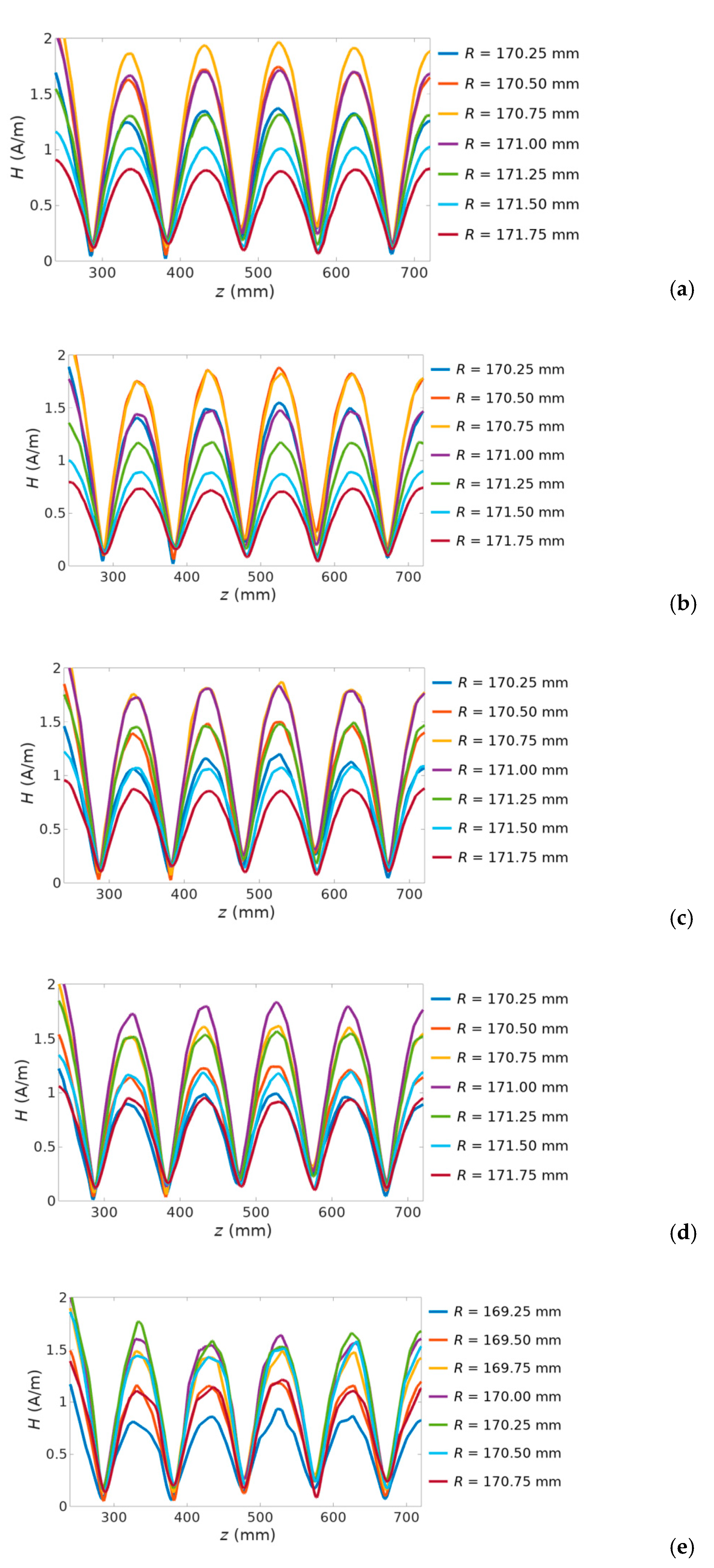
To analyze the resonance in the microwave chamber, the dependency of the distribution of the electromagnetic field strength
H was calculated along the line in the
Z-axis direction, as presented in
Figure 5. Electromagnetic field strength
H distributions are plotted as a function of both chamber’s radius
R and mesh parameter
hmax, presented in
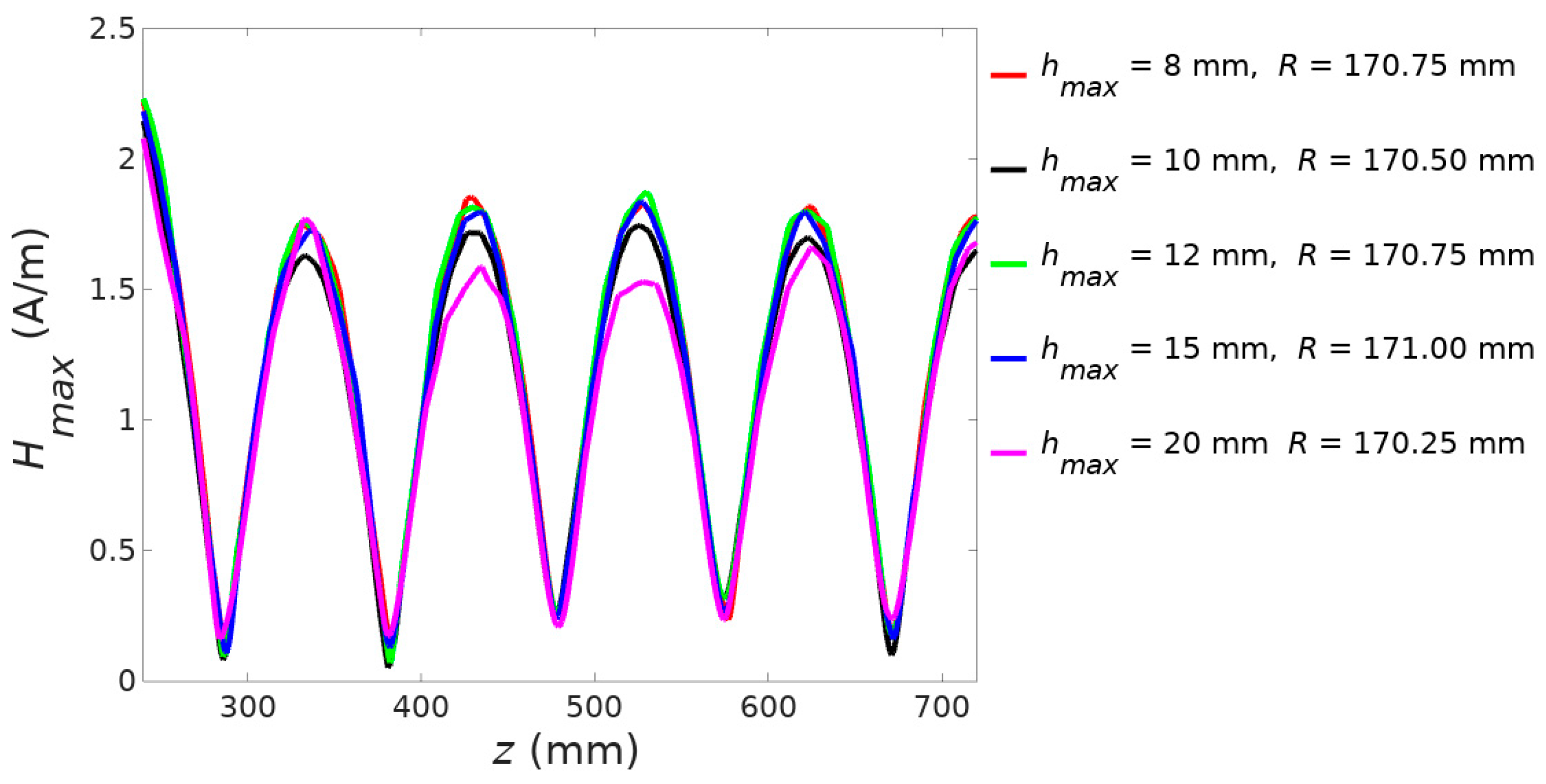
Figure 6. On the base of the results presented in
Figure 6, the plots of resonant electromagnetic field strength
H distributions are displayed in
Figure 7.
The presented results clearly indicate that meshing granularity hmax has a strong influence on the results of electromagnetic field strength H distribution on microwave chamber resonance. It should be highlighted that for different mesh granularity values of hmax, resonance occurs for different positions on the line in the Z-axis of the resonant chamber. For mesh granularity hmax values between 8 mm and 20 mm, the parameter R varies from 170.25 mm to 171.00 mm.
In addition, for higher mesh granularity
hmax, artefacts in the spatial distribution of maximal values of
H occur. It can be observed in
Figure 6 that for
hmax = 20 mm, values of maximal
H values near the centre of resonant chamber are smaller than near its edge. For smaller granularities (e.g., for
hmax = 8 mm), the spatial distribution of values of amplitudes in the maxima of the
H plot corresponds to the expected physical phenomena. Maxima of
H values near the centre of the chamber are higher than near the edge of resonant chamber.
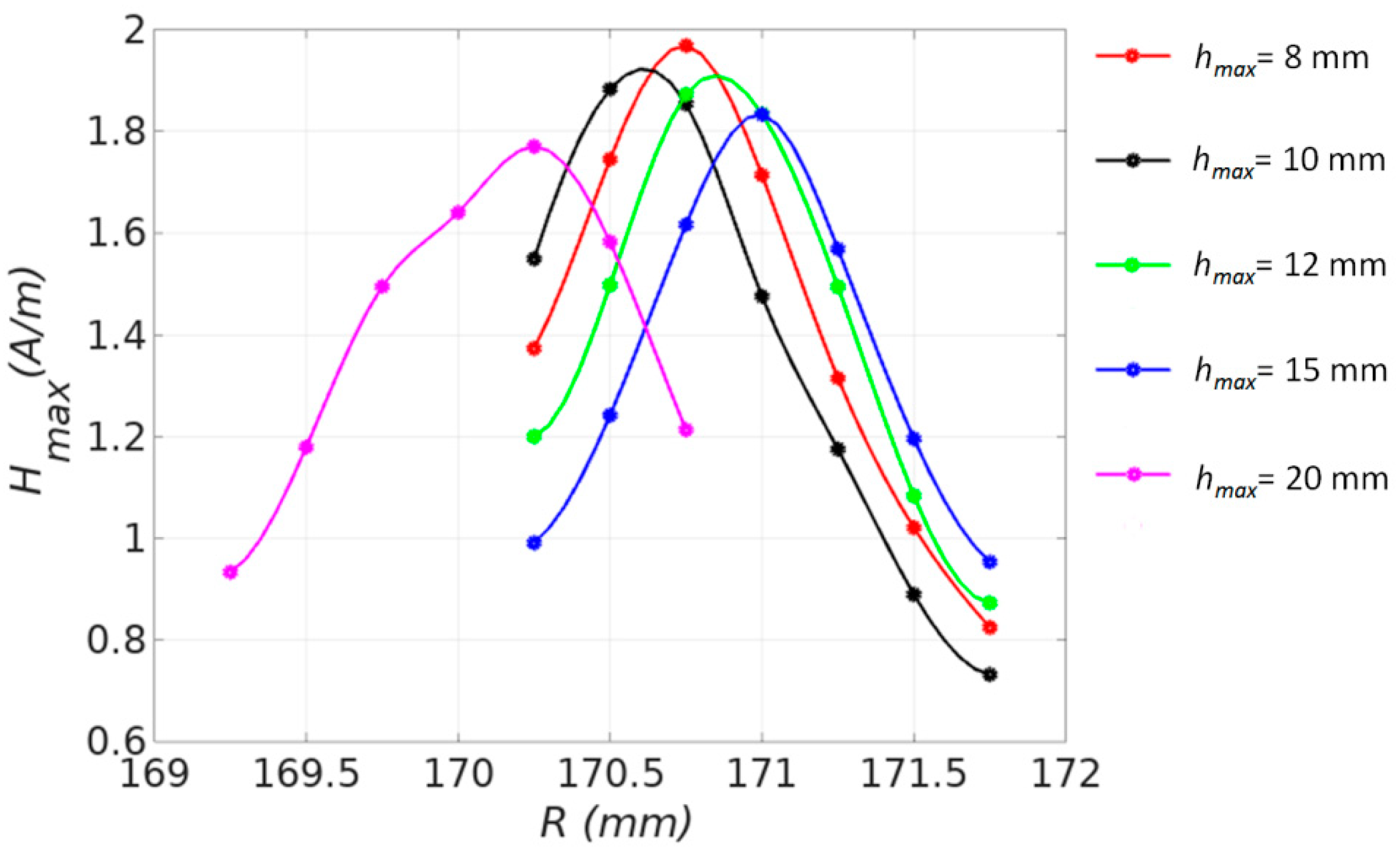
The presented results may lead to significant confusion during modelling in the development of microwave resonant chambers for practical applications. The radius of the resonant chamber R is critical from a practical perspective; however, it is dependent on mesh granularity hmax in the model.
Figure 8 presents the idea of overcoming this problem. It is evident that the required radius
R of the resonant chamber is convergent to a given value as a function of mesh granularity parameter
hmax.
The results of modelling presented in
Figure 8 clearly confirm that the required radius
R of the microwave resonant chamber is equal to 170.75 mm. In addition, the influence of the accuracy of microwave resonant chamber dimensions on its effectiveness may be estimated from
Figure 8.
On the other hand, it should be indicated that a decrease of mesh granularity (connected with decreasing of parameter hmax) leads to an increase in the number of tetrahedral mesh elements in a third power proportion. As a result, reduction of the granularity of the model must be done carefully to avoid overcoming the computing power and memory resources of the available computer.
In addition, the presented results clearly indicate that the height of the tetrahedral elements can be much bigger than the accuracy of estimation of the geometry of the resonant chamber. This effect relates to spatial averaging during the finite element method modelling. As a result, the efficient modelling of the microwave resonant chamber may be carried out with reasonable computing power and memory resources.
5. Conclusions
The presented results clearly confirm that microwave resonant chambers necessary for technical applications may be efficiently modelled on the base of open-source software tool chains covering mainly NETGEN mesher, ELMER FEM finite elements solver as well as PARAVIEW visualization software.
It should be highlighted that the results of finite elements modelling of resonant chamber diameters significantly vary from the results achieved on the base of commonly known, generalized and simplified equations. This is connected with the fact that shapes of resonant chambers used in practice significantly vary from simplified theoretical shapes and can be influenced by, e.g., connected waveguides.
On the other hand, mesh granularity, described by the maximal height of tetrahedral element hmax, may significantly influence the results of modelling. The present article proposed an iterative method of modelling while decreasing the granularity parameter hmax. With the use of this proposed method, the resonant chamber’s dimensions may be determined with the required degree of accuracy; additionally, one can avoid overcoming the computing power and memory resources of the available computer.
In addition, due to spatial averaging during the finite element method, the height of tetrahedral elements can be much bigger than the accuracy of estimation of the geometry of the resonant chamber. This effect is very useful in the case of development and modelling of microwave resonant chambers for practical applications.
It should be highlighted that modelling microwave chambers and cavities in a resonant state is a diversified task. The present paper presents a specific example as well as a concept of a universal method of identification of the parameters of geometry of such chambers, especially microwave chambers for drying equipment. Further works should be focused on microwave chemistry and miniature microwave resonant chambers for materials physics research. In such a case, a material located in the resonant chamber or cavity can significantly influence the resonant condition. Such an influence may be also modelled, enabling optimization of functional parameters of resonant chambers or miniature cavities according to the needs of the microwave chemistry of given physical processes.
Author Contributions
Conceptualization, D.K., A.O.-L. and R.S.; methodology, A.O.-L., D.K., P.R.; software, D.K., P.R., A.O.-L. and P.R.; validation, J.S.; formal analysis, D.K.; investigation, D.K., A.O.-L. and R.S.; data curation, D.K. and A.O.-L.; writing—original draft preparation, D.K., A.O.-L. and R.S.; writing—review and editing, D.K., A.O.-L., J.S., P.R. and R.S.; visualization, D.K. and A.O.-L.; supervision, A.O.-L. All authors have read and agreed to the published version of the manuscript.
Funding
This research received no external funding.
Institutional Review Board Statement
Not applicable.
Informed Consent Statement
Not applicable.
Data Availability Statement
Not applicable.
Conflicts of Interest
The authors declare no conflict of interest.
References
- Golio, M. (Ed.) The RF and Microwave Handbook; CRC Press: Boca Raton, FL, USA, 2000. [Google Scholar] [CrossRef]
- Forrest, J.R. Communication networks for the new millennium. IEEE Trans. Microw. Theory Tech. 1999, 47, 2195–2201. [Google Scholar] [CrossRef]
- Chung, B.; Chuah, H.; Bredow, J. A microwave anechoic chamber for radar-cross section measurement. IEEE Antennas Propag. Mag. 1997, 39, 21–26. [Google Scholar] [CrossRef]
- Gupta, M.; Wong, W.L.E. Microwaves and Metals; John Wiley & Sons: Hoboken, NJ, USA, 2008. [Google Scholar]
- Sakemi, D.; Serpone, N.; Horikoshi, S. Search for the Microwave Nonthermal Effect in Microwave Chemistry: Synthesis of the Heptyl Butanoate Ester with Microwave Selective Heating of a Sulfonated Activated Carbon Catalyst. Catalyst 2021, 11, 466. [Google Scholar] [CrossRef]
- Laguerre, J.-C.; Hamoud-Agha, M.M. Microwave Heating for Food Preservation. In Food Preservation and Waste Exploitation; IntechOpen: London, UK, 2020. [Google Scholar] [CrossRef]
- Menéndez, J.; Arenillas, A.; Fidalgo, B.; Fernández, Y.; Zubizarreta, L.; Calvo, E.; Bermúdez, J. Microwave heating processes involving carbon materials. Fuel Process. Technol. 2010, 91, 1–8. [Google Scholar] [CrossRef] [Green Version]
- Atwater, J.E.; Wheeler, R.R., Jr. Complex permittivities and dielectric relaxation of granular activated carbons at micro-wave frequencies between 0.2 and 26 GHz. Carbon 2003, 41, 1801–1807. [Google Scholar] [CrossRef]
- Atwater, J.E.; Wheeler, R.R., Jr. Temperature dependent complex permittivities of graphitized carbon blacks at microwave frequencies between 0.2 and 26 GHz. J. Mater. Sci. 2004, 39, 151–157. [Google Scholar] [CrossRef]
- Atwater, J.E.; Wheeler, R.R., Jr. Microwave permittivity and dielectric relaxation of a high surface area activated carbon. Appl. Phys. A 2004, 79, 125–129. [Google Scholar] [CrossRef]
- Verma, D.K.; Mahanti, N.K.; Thakur, M.; Chakraborty, S.K.; Srivastav, P.P. Microwave Heating: Alternative Thermal Process Technology for Food Application. In Emerging Thermal and Nonthermal Technologies in Food Processing; Apple Academic Press: Cambridge, MA, USA, 2020; pp. 25–67. [Google Scholar] [CrossRef]
- Yuen, F.K.; Hameed, B.H. Recent developments in the preparation and regeneration of activated carbons by microwaves. Adv. Colloid Interface Sci. 2009, 149, 19–27. [Google Scholar] [CrossRef] [PubMed]
- Hasna, A.M. Curing starch based adhesives: Microwave or conventional. Int. J. Mater. Prod. Technol. 2003, 19, 259. [Google Scholar] [CrossRef]
- Bergese, P.; Colombo, I.; Gervasoni, D.; Depero, L. Microwave generated nanocomposites for making insoluble drugs soluble. Mater. Sci. Eng. C 2003, 23, 791–795. [Google Scholar] [CrossRef]
- Lu, A.; Zhang, S.; Shan, X.-Q.; Wang, S.; Wang, Z. Application of microwave extraction for the evaluation of bioavailability of rare earth elements in soils. Chemosphere 2003, 53, 1067–1075. [Google Scholar] [CrossRef]
- Meda, V.; Orsat, V.; Raghavan, V. Microwave heating and the dielectric properties of foods. Microw. Process. Foods 2017, 23–43. [Google Scholar] [CrossRef]
- Datta, A.K. Handbook of Microwave Technology for Food Application; CRC Press: Boca Raton, FL, USA, 2001. [Google Scholar]
- Bykov, Y.V.; Rybakov, K.; Semenov, V.E. High-temperature microwave processing of materials. J. Phys. D Appl. Phys. 2001, 34, R55–R75. [Google Scholar] [CrossRef]
- Cid, B.P.; Alborés, A.F.; Gómez, E.F.; López, E.F. Use of microwave single extractions for metal fractionation in sewage sludge samples. Anal. Chim. Acta 2001, 431, 209–218. [Google Scholar] [CrossRef]
- Varma, R.S. Microwave Technology-Applications in Chemical Synthesis. Kirk-Othmer Encycl. Chem. Technol. 2013, 1–68. [Google Scholar] [CrossRef]
- Zong, L.; Zhou, S.; Sgriccia, N.; Hawley, M.; Kempel, L. A Review of Microwave-Assist Polymer Chemistry (MAPC). J. Microw. Power Electromagn. Energy 2003, 38, 49–74. [Google Scholar] [CrossRef]
- Hernandez, M.; Gonzalez, M. Synthesis of resins as alpha-alumina precursors by the Pechini method using microwave and infrared heating. J. Eur. Ceram. Soc. 2002, 22, 2861–2868. [Google Scholar] [CrossRef]
- Tata, A.; Beone, F. Hospital waste sterilization: A technical and economic comparison between radiation and microwaves treatments. Radiat. Phys. Chem. 1995, 46, 1153–1157. [Google Scholar] [CrossRef]
- Harris, G.A.; Brodie, G.; Ozarska, B.; Taube, A. Design of a Microwave Chamber for the Purpose of Drying of Wood Components for Furniture. Trans. ASABE 2011, 54, 363–368. [Google Scholar] [CrossRef]
- Jackson, J.D.; Fox, R.F. Classical Electrodynamics, 3rd ed. Am. J. Phys. 1999, 67, 841–842. [Google Scholar] [CrossRef]
- Zienkiewicz, O.; Taylor, R.; Zhu, J. The Finite Element Method: Its Basis and Fundamentals; Elsevier: Amsterdam, The Netherlands, 2013. [Google Scholar] [CrossRef]
- Marfurt, K.J. Accuracy of finite-difference and finite-element modeling of the scalar and elastic wave equations. Geophysic 1984, 49, 533–549. [Google Scholar] [CrossRef]
- Liu, Y.; Glass, G.A. Effects of Mesh Density on Finite Element Analysis; SAE Technical Paper Series; SAE International: Warrendale, PA, USA, 2013; Volume 2. [Google Scholar] [CrossRef]
- Roth, S. Influence of mesh density on a finite element model’s response under dynamic loading. J. Biol. Phys. Chem. 2009, 9, 210–219. [Google Scholar] [CrossRef]
- Ghavidel, A.; Mousavi, S.R.; Rashki, M. The Effect of FEM Mesh Density on the Failure Probability Analysis of Structures. KSCE J. Civ. Eng. 2018, 22, 2370–2383. [Google Scholar] [CrossRef]
- Råback, P.; Forsström, P.-L.; Lyly, M.; Gröhn, M. Elmer-finite element package for the solution of partial differential equa-tions. In EGEE User Forum; CSC: Espoo, Finland, 2007. [Google Scholar]
- (108) Elmer FEM Webinar—Microwave Modeling in Elmer—YouTube. Available online: https://www.youtube.com/watch?v=aGf4sC5q0QE (accessed on 27 July 2021).
- Luan, D.; Wang, Y.; Tang, J.; Jain, D. Frequency Distribution in Domestic Microwave Ovens and Its Influence on Heating Pattern. J. Food Sci. 2017, 82, 429–436. [Google Scholar] [CrossRef]
- Ishimaru, A. Electromagnetic Wave Propagation, Radiation, and Scattering: From Fundamentals to Applications; John Wiley & Sons: Hoboken, NJ, USA, 2017. [Google Scholar]
- Nyfors, E.G. Cylindrical Microwave Resonator Sensors for Measuring Materials under Flow; Helsinki University of Technology Radio Laboratory Publications: Helsinki, Finland, 2000. [Google Scholar]
- Magnusson, P.C.; Weisshaar, A.; Tripathi, V.K.; Alexander, G.C. Transmission Lines and Wave Propagation, 4th ed.; CRC Press: Boca Raton, FL, USA, 2000. [Google Scholar] [CrossRef]
- Main Page—Linux Mint. Available online: https://linuxmint.com/ (accessed on 8 April 2020).
- Top (GNU Octave (Version 5.2.0)). Available online: https://octave.org/doc/v5.2.0/ (accessed on 25 April 2020).
- Netgen/NGSolve. Available online: https://ngsolve.org/ (accessed on 23 November 2020).
- Arnold, N. Numerische Lösungen Elliptischer und Parabolischer Differentialgleichungen in Zwei und Drei Dimensionen Mit NETGEN/NGSolve. Master’s Thesis, University of Zürich, Zürich, Switzerland, 2013. [Google Scholar]
- Schöberl, J. NETGEN An advancing front 2D/3D-mesh generator based on abstract rules. Comput. Vis. Sci. 1997, 1, 41–52. [Google Scholar] [CrossRef]
- Szałatkiewicz, J.; Szewczyk, R.; Kalinowski, M.; Kataja, J.; Råback, P.; Ruokolainen, J.; Kachniarz, M. Open source ELMER software based FEM modeling of waveguides and resonant cavities for microwave heating and drying devices. Arch. Electr. Eng. 2017, 66, 745–750. [Google Scholar] [CrossRef] [Green Version]
- ParaView. Available online: https://www.paraview.org/ (accessed on 25 April 2020).
- Ahrens, J.; Geveci, B.; Law, C. ParaView: An End-User Tool for Large-Data Visualization; Elsevier BV: New York, NY, USA, 2005; pp. 717–731. [Google Scholar]
- Cignoni, P.; Montani, C.; Scopigno, R. DeWall: A fast divide and conquer Delaunay triangulation algorithm in Ed. Comput. Des. 1998, 30, 333–341. [Google Scholar] [CrossRef]
- Råback, P.; Malinen, M.; Ruokolainen, J.; Pursula, A.; Zwinger, T. Elmer Models Manual. Available online: https://www.nic.funet.fi/index/elmer/doc/ElmerModelsManual.pdf (accessed on 10 April 2020).
| Publisher’s Note: MDPI stays neutral with regard to jurisdictional claims in published maps and institutional affiliations. |
© 2021 by the authors. Licensee MDPI, Basel, Switzerland. This article is an open access article distributed under the terms and conditions of the Creative Commons Attribution (CC BY) license (https://creativecommons.org/licenses/by/4.0/).


 ,
, 


