
Design of JET Humanoid Robot with Compliant Modular Actuators for Industrial and Service Applications
by
 , , , , and
Jaehoon Sim
1 ,
,
Seungyeon Kim
1,
Suhan Park
1,
Sanghyun Kim
2,
Mingon Kim
1 and
Jaeheung Park
1,3,* 1
Graduate School of Convergence Science and Technology, Seoul National University, Seoul 08826, Korea
2
Korea Institute of Machinery and Materials (KIMM), Daejeon 34103, Korea
3
Advanced Institute of Convergence Technology (AICT), Suwon 16229, Korea
*
Author to whom correspondence should be addressed.
Appl. Sci. 2021, 11(13), 6152; https://doi.org/10.3390/app11136152
Submission received: 31 May 2021
/
Revised: 26 June 2021
/
Accepted: 30 June 2021
/
Published: 2 July 2021
(This article belongs to the Special Issue Modelling and Control of Mechatronic and Robotic Systems, Volume II)
Abstract
:This paper presents the development of the JET humanoid robot, which is based on the existing THORMANG platform developed in 2015. Application in the industrial and service fields was targeted, and three design concepts were determined for the humanoid robot. First, low stiffness of the actuator modules was utilized for compliance with external environments. Second, to maximize the robot whole-body motion capability, the overall height was increased. However, the weight was reduced to satisfy power requirements. The workspace was also increased to enable various postures, by increasing the range of motion of each joint and extending the links. Compared to the original THORMANG platform, the lower limb length increased by approximately 20%, and the hip range of motion increased by 39.3%. Third, the maintenance process was simplified through modularization of the electronics and frame design for improved accessibility. Several experiments, including stair climbing and egress from a car, were performed to verify that the JET humanoid robot performance enhancements reflected the design concepts.
1. Introduction
Robots have many increasingly different applications. Recently, their feasibility in various service and industry settings, where interaction with humans or environments is required, has been explored. Among the many possible robot forms for these applications, humanoids can be very effective as they have similar kinematic structures to humans. That is, utilizing two arms and two legs, humanoid robots can perform various tasks in a human-centered environment. In particular, the DARPA Robotics Challenge (DRC) Finals in 2015 demonstrated the potential of humanoid robots for use in disaster-response scenarios [1]. Furthermore, the use of humanoid robots in industrial applications, such as airplane assembly and nuclear power plant cleaning, is now being actively investigated [2].
As humanoid robots are required to interact with people as well as the environment in industry and service applications, both high performance and safety are important. Thus, several design features should be considered: compliance with unexpected external forces, whole-body motion capability through an increased workspace, and straightforward maintenance.
Compliance reduces the physical damage or instability from unexpected collisions between the robot and external objects and is an essential design consideration for a humanoid robot. There are two approaches to achieving compliance: hardware methods using low-stiffness actuators and software approaches such as torque-based controllers and impedance controllers [3,4]. Recently, a method for controlling compliant contact with objects has been proposed through an optimization-based approach [5]. In addition, artificial intelligence-based methods of controlling desired compliance have also been introduced for many applications [6]. However, software methods are limited by their dependence on the performance of a sensory system, with their compliance bandwidth limited by those of the sensors and control systems. Furthermore, if a sensor malfunction or software failure occurs, robot compliance cannot be guaranteed. Therefore, humanoid robots with low-stiffness actuators have recently been developed [7,8].
Second, whole-body motion capability is fundamental for various tasks, and a large robot workspace enhances this capability. In the DRC Finals, most teams reported whole-body motion planning as a main factor determining manipulation capability in human-centered environments [9]. For instance, the robot should have the capability to perform complex tasks such as stair climbing, driving, and exiting a vehicle.
Finally, and most importantly, industrial and service humanoids should be easy to maintain. As humanoid robots frequently interact with humans or objects, they require periodic maintenance to avoid malfunction. Modularization is a dominant approach to easy maintenance and is adopted for many robots [10].
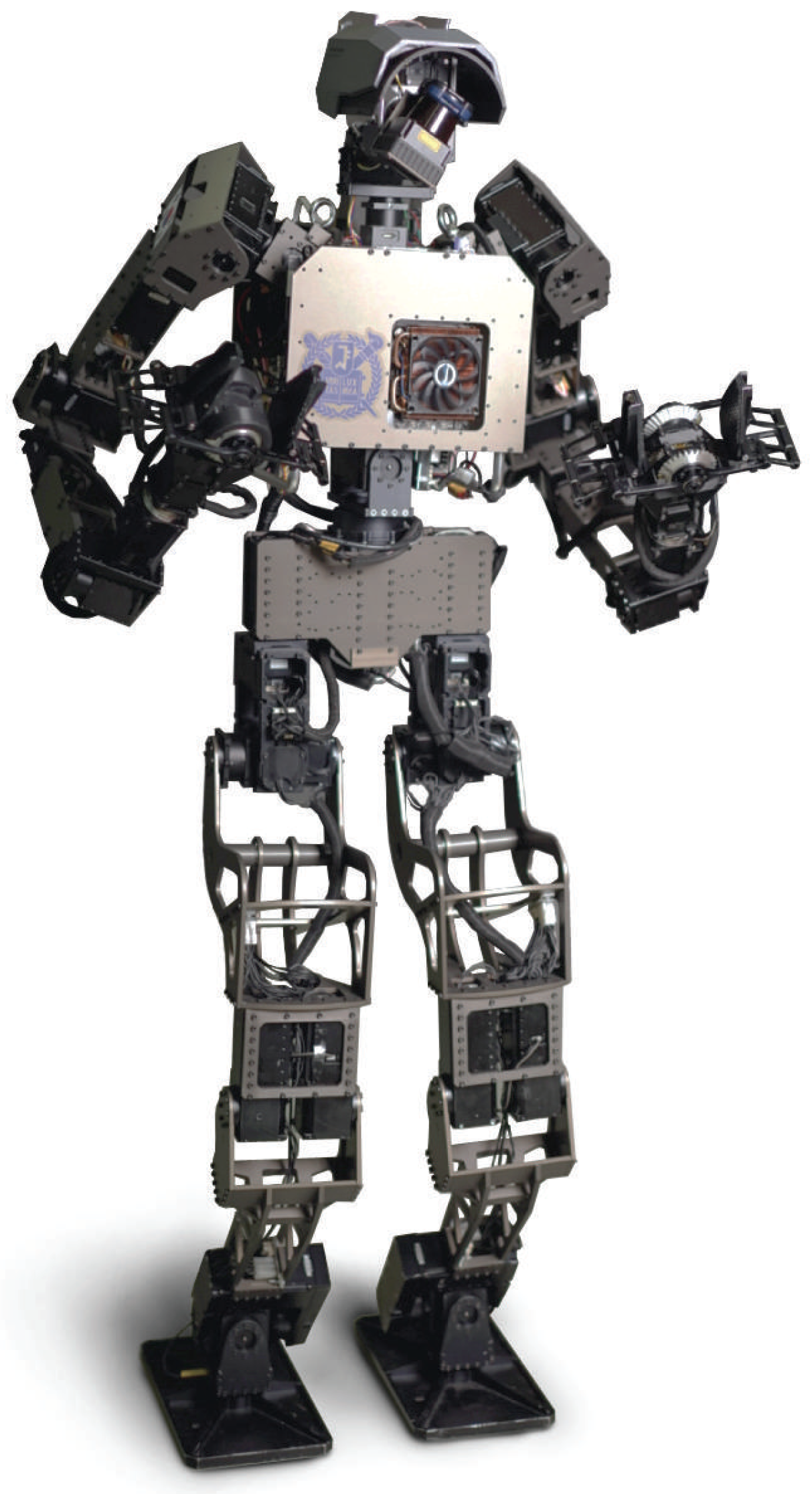
In this study, the JET humanoid platform shown in Figure 1 is introduced to implement the three features listed above. JET was developed on the basis of THORMANG, which was developed by ROBOTIS and was modified by TEAM SNU for the DRC Finals [11]. Through the new design proposed herein, JET overcomes the THORMANG platform limitations while conserving its advantages. The main aim of the new design is to acquire more practical capabilities suited to industrial and service applications.
The remainder of this paper is organized as follows. Section 2 describes the THORMANG platform specifications and our design goals, while Section 3 presents the newly developed JET humanoid robot design. Section 4 reports experimental validation of the developed robot and Section 5 concludes the paper.
2. Design Goal Selection
This section presents the specifications of our previous humanoid robot platform, THORMANG, and the design goals of our newly proposed humanoid robot for maximized performance.
2.1. Limitation of THORMANG Platform
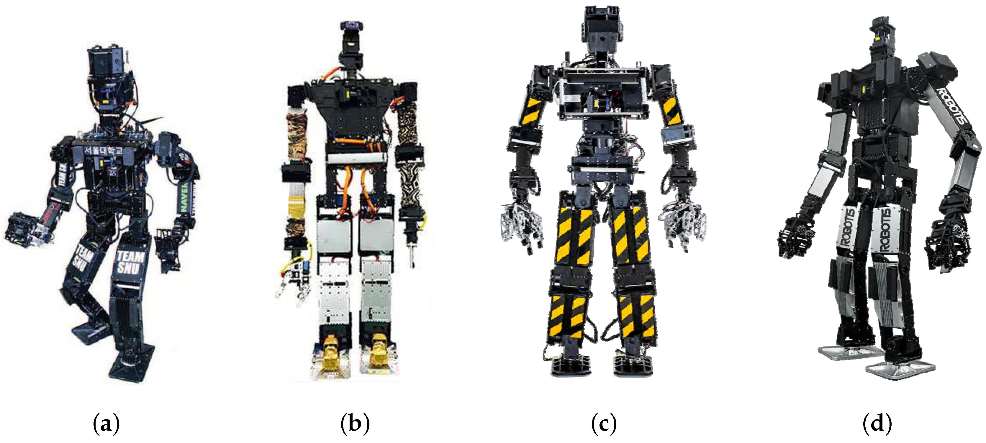
THORMANG, which was developed by ROBOTIS, is an open source platform humanoid. This robot has two representative characteristics. First, THORMANG is modular and can, therefore, be easily modified according to user aims. For example, although four teams used the THORMANG platform at the DRC Finals (TEAM SNU, TEAM THOR, TEAM, Hector, and TEAM Robotis), the robot shapes, sizes, and weights varied, as shown in Figure 2 [11].
Second, THORMANG employs Dynamixel Pro, which is an actuator module developed as a commercial product by ROBOTIS. Dynamixel Pro has low stiffness, which is more comparable to a series elastic actuator (SEA) than to other conventional electric actuators with harmonic drives. The SHG-17-100-2SO harmonic drive, which has a similar torque capacity to Dynamixel Pro, has a stiffness of 10,000 Nm/rad or higher [12,13]. In contrast, SEAs for humanoids have a lower stiffness of 500–10,000 Nm/rad [14,15]. Notably, the H54-200-S500-R Dynamixel Pro stiffness is 900 Nm/rad, on a similar scale as the COMAN and WALKMAN SEAs [16]. As mentioned above, mechanical compliance from low-stiffness actuators aids robot control in complex multiple-contact situations, as it can provide robustness to the disturbance caused by unexpected contact with external objects.
However, the THORMANG platform has several limitations in terms of robot performance. First, the robot kinematic structure is not suited to various tasks in human-centered environments such as industrial and service sites. Humanoids require whole-body motion capability to perform diverse tasks, but the THORMANG leg length is insufficient and the joint ranges are limited. In the DRC Finals, all THORMANG-based robots failed the egress task, as detailed in Table 1, because the robot could not reach the floor while sitting in the vehicle. Further, the stair task, which required the robot to climb a staircase, was one of the most difficult tasks for the THORMANG-based designs because of their short legs and narrow workspace [11]. To statically climb the stairs, the knees required sufficient bending for lateral movement. To move the center of mass (COM) over the feet on the stairs, it was necessary for the leg joints to rotate by more than the shorter length between the hip and foot. On a step with a 24 cm height, self-collision of the hip and knee joints occurred because of the short legs of the THORMANG design.
Second, unmeasurable deformation occurred at the hip joints because of the high lower body weight and actuator module compliance. The lower body of the original THORMANG platform consists of two lithium polymer (LiPo) batteries (22,000 mAh, 22.2 V) and heavy links [17]. Therefore, when the robot walks, the pelvis tilt is so extensive that control of the swing foot is very difficult. During the DRC competition, most THORMANG-based robots, excluding that of TEAM SNU, fell when walking.
Therefore, we concentrated on developing our hardware to upgrade the performance and overcome the above limitations.
2.2. Design Goals
In addition to overcoming the above THORMANG limitations, to achieve compliance, whole-body motion capability, and easy maintenance, as mentioned in Section 1, the following three philosophies were adopted as the JET design goals.
First, increasing the lower body workspace allows a robot to fit various situations. As main structures such as stairs, seats, and ladders are designed for humans, a proper leg length is advantageous. Furthermore, the robot range of motion (ROM) can be increased by avoiding self-collision. Hence, the designed robot can perform various motions such as full squats.
Second, robot weight reduction is necessary for increased energy efficiency and to alleviate actuator loads. However, increasing the link length to enhance the robot workspace can overload the actuators. To solve this problem, we considered better weight distribution as well as weight reduction for JET.
Third, easy maintenance is important for increased economic feasibility. Thus, the JET links are composed of many small parts. We designed most link parts to have a flat shape for easy laser cutting, which is cheaper and quicker than milling. Additionally, the frames containing actuators and circuits were designed to be easily removable for easy disassembly and assembly.
3. JET Design
As detailed in Table 2, the height, weight, and wingspan of the developed robot are 1.63 m, 48 kg, and 2.12 m, respectively. Other robots, including TALOS, HRP-5P, and former THORMANG platforms, and human characteristics are also shown in Table 2. Similar to the THORMANG platforms, TALOS is a commercial off-the-shelf research platform which is developed by PAL-Robotics [18]. HRP-5P is an adult-sized humanoid developed to realize the use of humanoids in large-scale assembly industries. Compared with the THORMANG of Team SNU, JET is taller and lighter. However, JET is heavier than THORMANG3, the latest released version from ROBOTIS because THORMANG3 is the shortest platform among all of the THORMANG platforms. Both THORMANG3 and JET are developed on the basis of THORMANG, but THORMANG3 is designed to focus on increasing speed by reducing size. On the other hand, JET is designed to focus on the workspace to conduct difficult tasks, such as egress from the vehicle and climbing stairs in the DRC Finals, for THORMANG due to its small size. With a similar leg length to JET, TALOS is taller but much heavier due to stronger actuators and torque sensors. Developed to perform a variety of industrial tasks with a wide joint range, HRP-5P has 23 mm longer legs, and it is taller than JET. However, HRP-5P is much heavier due to its larger degrees of freedom (DOF) and stronger actuators. Notably, the JET height, weight, and leg length are similar to the averages for Korean young women aged 20–24 [19]. Due to the torque capacity of the hip pitch joint, the length of each link in the shin and thigh was adjusted. Therefore, the JET hardware specifications are suitable for performance of various complex tasks in a human-centered environment.
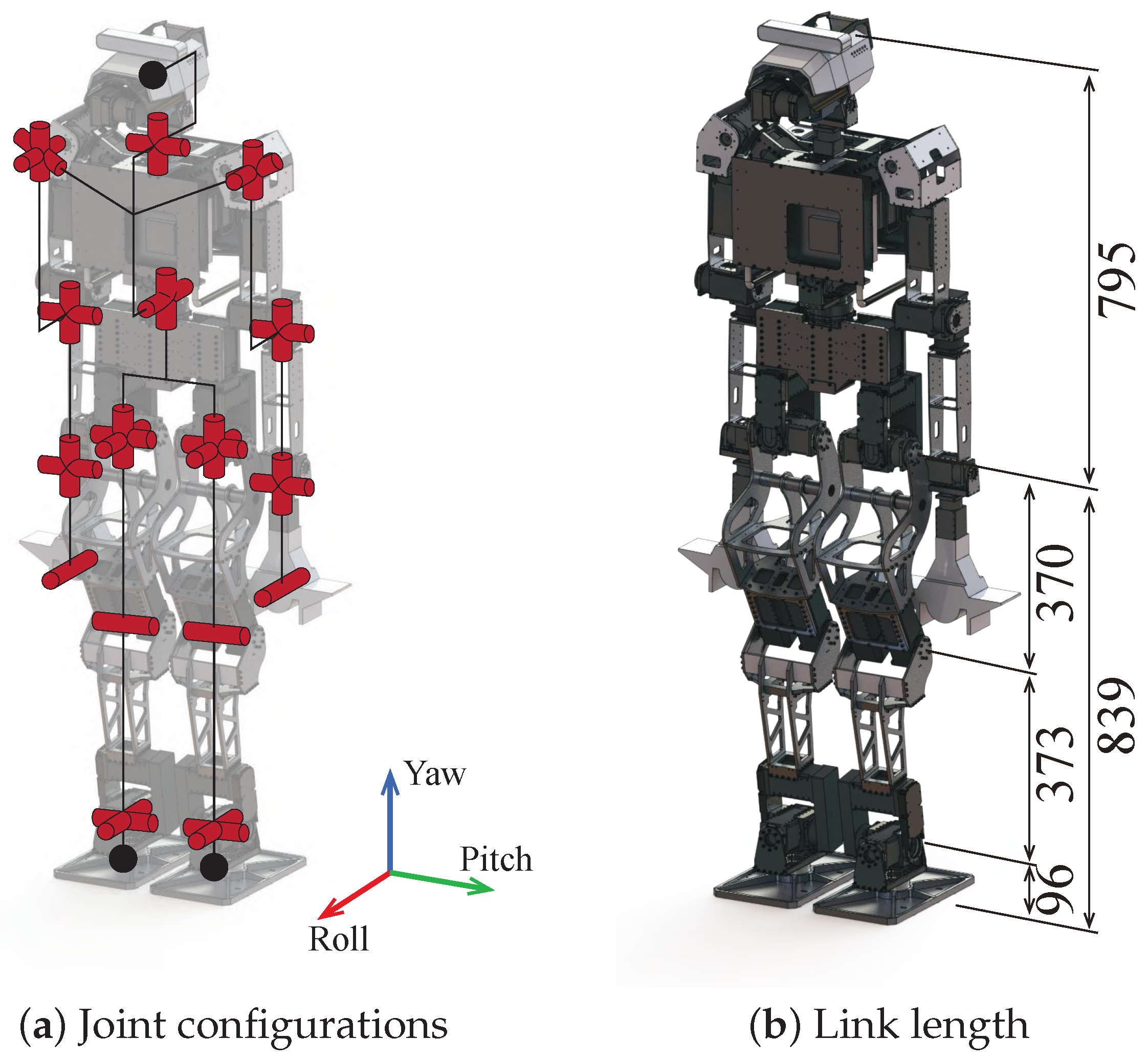
Figure 3 shows the JET joint configuration, which consists of a total of 32 DOF, excluding the LiDAR actuator. There are eight joints in each arm with the end-effectors, six in each leg, two in the waist, and two in the head. In the waist, we used two DOF joints in the yaw and roll directions to increase not only the bipedal walking stability but also the robot workspace [22].
The following subsections present details of the proposed hardware, i.e., the electrical system and lower and upper body designs.
3.1. Electrical System Design
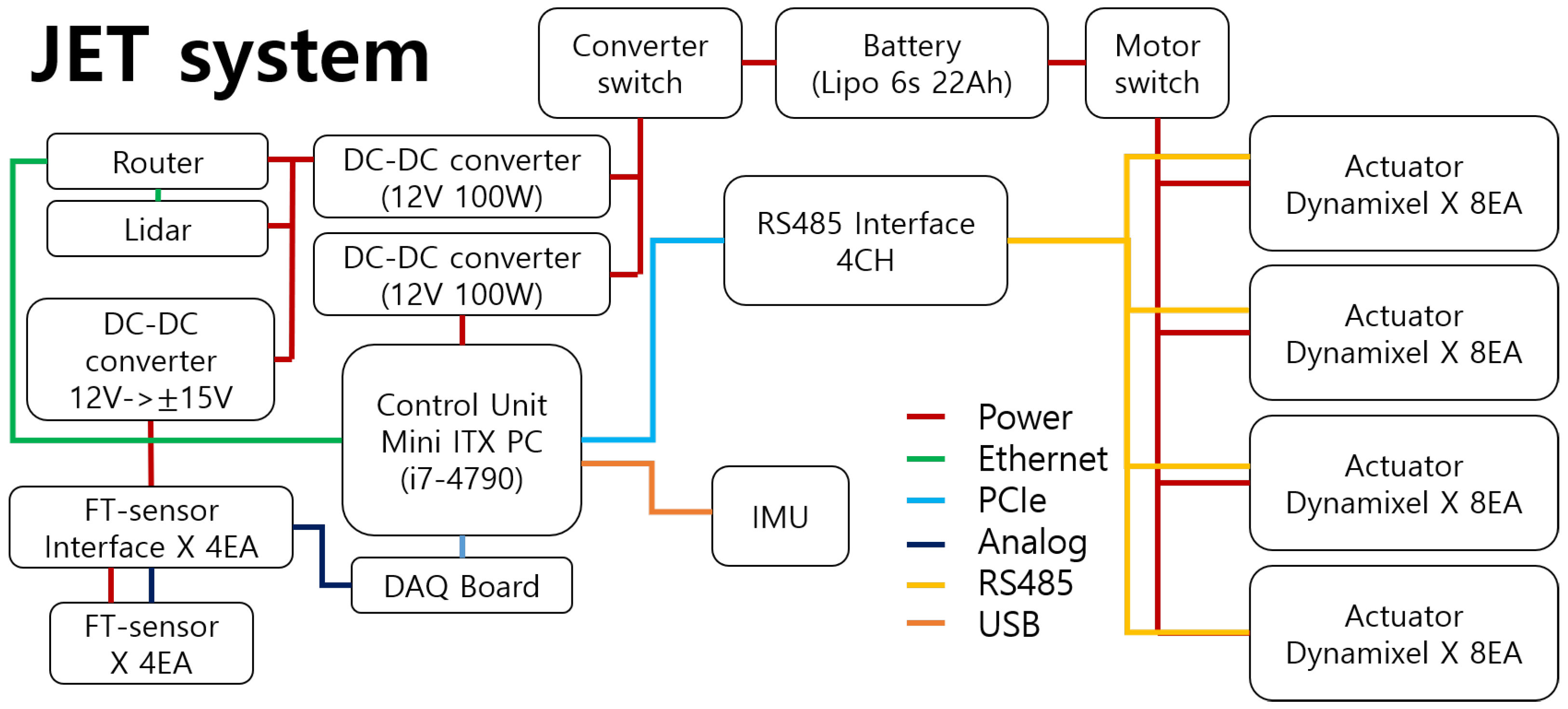
Figure 4 shows the overall electrical system of JET. A mini-ITX PC is used as the computing system, with the computer board being placed at the front of the robot’s chest. The computer CPU is an Intel Core i7-4790 Processor (3.6 GHz) to provide sufficient computation performance for robot control. The computer is equipped with a SENSORAY 826 DAQ board for acquiring analog sensor data and a DIAMOND DS-MPE-OPT4485 4-Port RS-485 MiniCard Module for actuator communication. Using a PCIe-based communication interface, JET can be controlled with a 200 Hz command rate. In contrast, the THORMANG command rate is 100 Hz [11].
To supply power to the robot, we designed a power system including regulators and a battery. To connect the battery, electronics, and regulators, wire connectors were unified with the same actuator connectors. Parts unification is a well-known method of reducing both manufacturing cost and maintenance. In the JET system, one LiPo (22,000 mAh, 22.2 V) battery supplies power to all actuators and voltage transformer modules. A voltage transformer module is composed of three DC–DC converters. To match the computer ground level with the actuators, two 12 V converters are nonisolated. However, the converter for the FT sensor interface is isolated to reduce the FT sensor power source noise. The sensor ground level is matched with the main ground via the DAQ board. The LiPo battery has excellent discharge performance and small voltage fluctuation, even under high load. On standby, JET consumes 5 A (0.2 C). The peak current while walking is 9 A (0.4 C); this is a small current compared to the LiPo battery discharge rate. Thus, the battery voltage fluctuations due to the discharge rate are sufficiently small to integrate the actuator power source with the computer source. With a fully charged LiPo battery, JET can stand for 4 h.
The sensory system required for humanoids includes an environment perception sensor and a measurement sensor of the robot state. Three sensor types are used for the perception system: one LiDAR, one IMU, and four FT sensors. A HOKUYO UTM-30LX-EW sensor, which is a 2D LiDAR, is mounted at the head to acquire 3D point cloud data of the robot surroundings; this is achieved by continuously rotating the sensor about its vertical axis. To facilitate continuous LiDAR rotation, a slip ring is used to connect the electric wires. A MicroStrain 3DM-GX4-25 IMU is placed at the robot coordinate origin in the pelvis. Finally, ATI Mini 58 and Mini 45 FT sensors are mounted on both feet and hands to measure the forces acting on the feet and wrists. Further system integration and software development details are given in our previous paper [23]. Using a robot operating system (ROS)-based system framework, JET can be controlled stably with many sensors and actuators.
3.2. Lower Body Design
The lower body design goal was to achieve a wide ROM. To accommodate various environments and obstacles tailored to an adult body, a wide lower body workspace is required. The foot workspace can be extended by increasing the leg length or by increasing the joint ROM. However, in the case of JET, the lower body length is limited by the robot actuator. Therefore, to secure a large working space, the ROM of each joint must be increased.
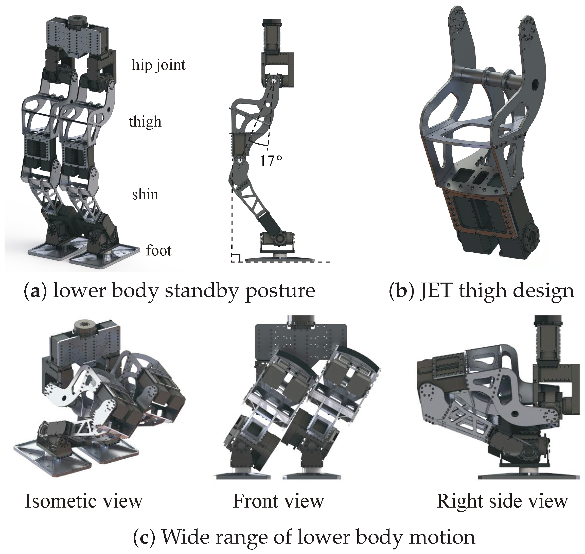
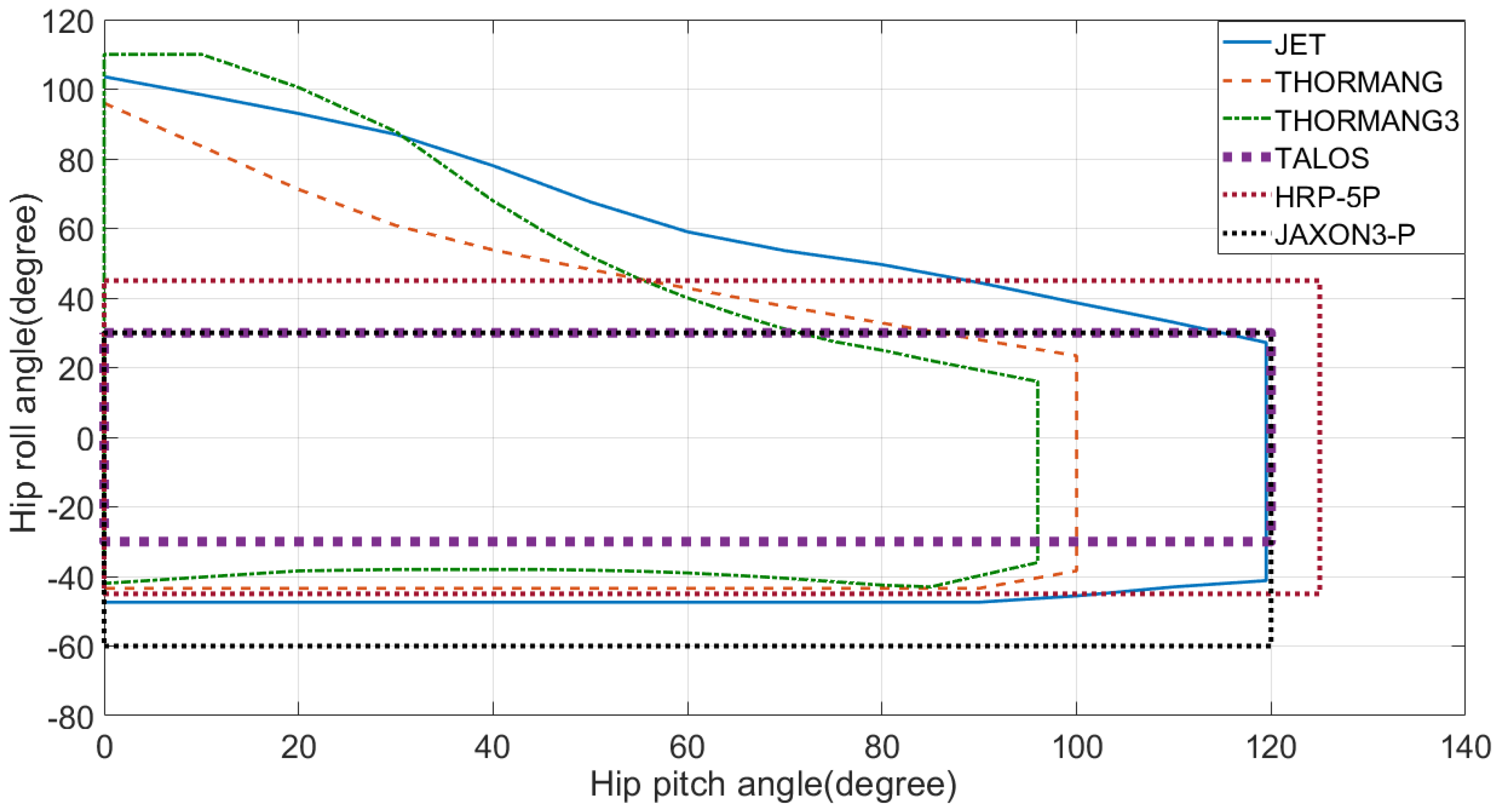
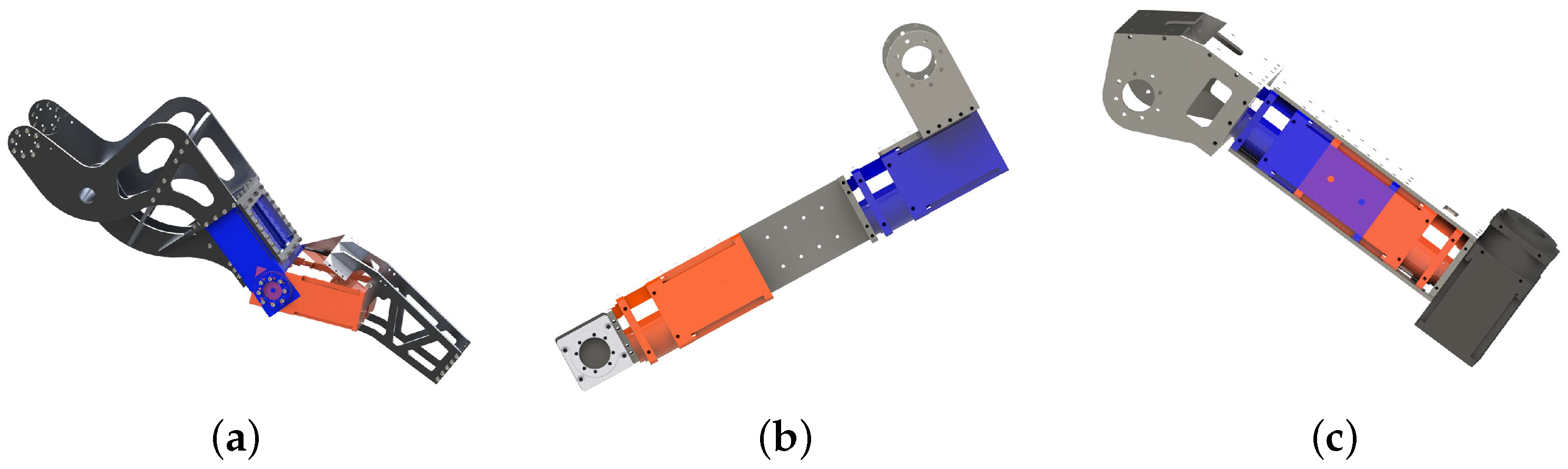
JET has the same hip joint structure as THORMANG. The hip joint consists of two actuators in roll-pitch order, as shown in Figure 5a, and each axis of rotation is orthogonal at the initial position. To increase the ROM, an S-shape thigh frame was devised, as shown in Figure 5b. This thigh frame reduces interference between the motor and thigh frames, thereby increasing the hip joint ROM, as shown in Figure 5c. Figure 6 compares the JET, THORMANG, THORMANG3, and TALOS ROMs. Because of self-collision, the ROM of one joint is not independent of another joint position. Thus, thigh frame was designed for ROM expansion when both hip joints bend. Hence, the ROM of the two hip joints was expanded by 39.3% and 36.7%, respectively, compared to THORMANG and THORMANG3. The hip joint ROM of TALOS, which is introduced in [18], is also smaller than the ROM of JET. The authors of [21] developed HRP-5P, which has larger hip roll ROM than that of JET when the pitch angle is 110°. JAXON3-P, which has a 1.7 m height and 70 kg weight, also has larger hip roll ROM than that of JET when the hip pitch is 110° [24]. To increase the knee ROM, the curves of the back of the thigh and shin frame were designed similarly, and the knee actuator was relocated from the shin to the thigh. These changes allow JET to perform more varied postures than THORMANG.
THORMANG has a larger upper-to-lower body height ratio than that of a typical young female with similar height, at 1:0.79 compared to 1:1, respectively. The large head, which includes many cameras, is one of the reasons for this difference. Generally, a humanoid robot with a shorter pelvis and lower shoulder height than humans has performance limitations for various tasks involving human life tools such as ladders and stairs.
The JET lower body design is based on the average body proportions of a young female for more natural behavior in industry and service applications. Thus, the lower body is lengthened from 696 to 839 mm compared to THORMANG. The the thigh length to shin length to ankle joint height ratio is 1:1:0.26, which is adjusted to the average ratio for a young female. Figure 3b shows the length of each part. With this leg length increase, the upper-to-lower body height ratio is almost 1:1.
In addition to the functional advantages, the S-shape thigh frame has aesthetic benefits, having a fuller shape than that of the shin and human-like body proportions. As shown in Figure 5c, the S-shape thigh frame seems to be stretching the knees in the standby pose, because the thigh front surface is perpendicular to the ground.
3.3. Upper Body Design
JET features a yaw and roll combination in the waist for the following reasons. First, downward tilting of the upper body in the forward direction is difficult, because the actuator has limited maximum torque. However, the waist pitch motion can be generated by the two hip pitch actuators. Second, the upper body roll motion is useful to control the center of mass in the lateral direction during walking [22,25]. This also extends the arm reach in the vertical direction. Finally, the yaw motion is useful to reverse the upper body orientation to avoid collision between obstacles and the shin, which protrudes during knee bending [11,26].
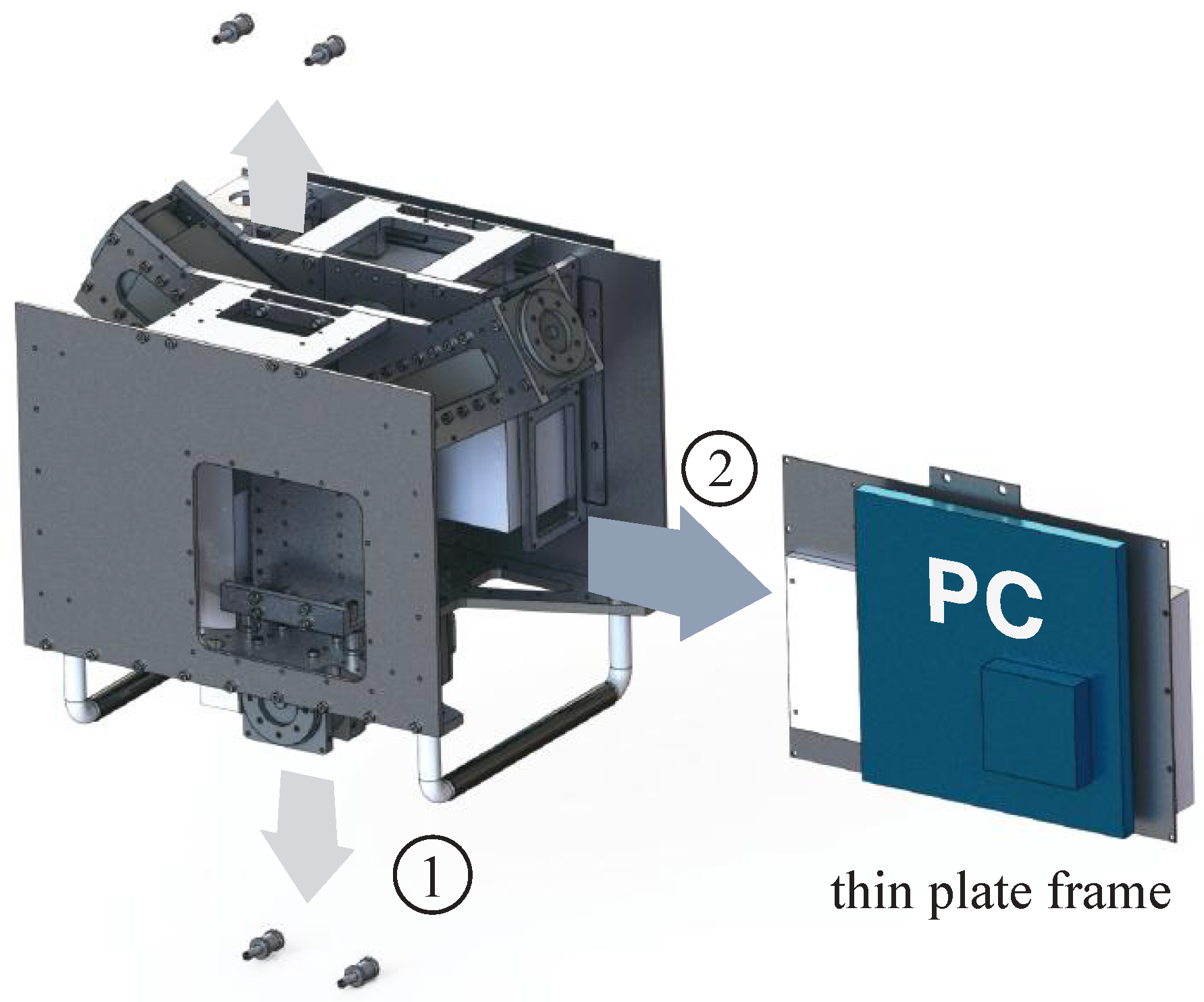
For easy maintenance, most electronic components are located on the open side of the torso. The advantage of this is that most electrical components can be accessed without disassembling the entire frame. The part where the circuit is fixed is modularized for easy assembly and disassembly. Figure 7 shows the torso and modularized computer design, which allows easy removal of the computer module from the robot.
3.4. Design for Load Alleviation
Greater leg length increases the moment of inertia as well as the gravity load of the same joint space configuration. As JET employs the same actuators as THORMANG, it was essential to alleviate the load in accordance with the actuator capacity. The frame weight was reduced by adding polygon holes. Through finite element analysis (FEA), a lightweight link was created that could maintain the strength to withstand an applied load without excessive deformation.
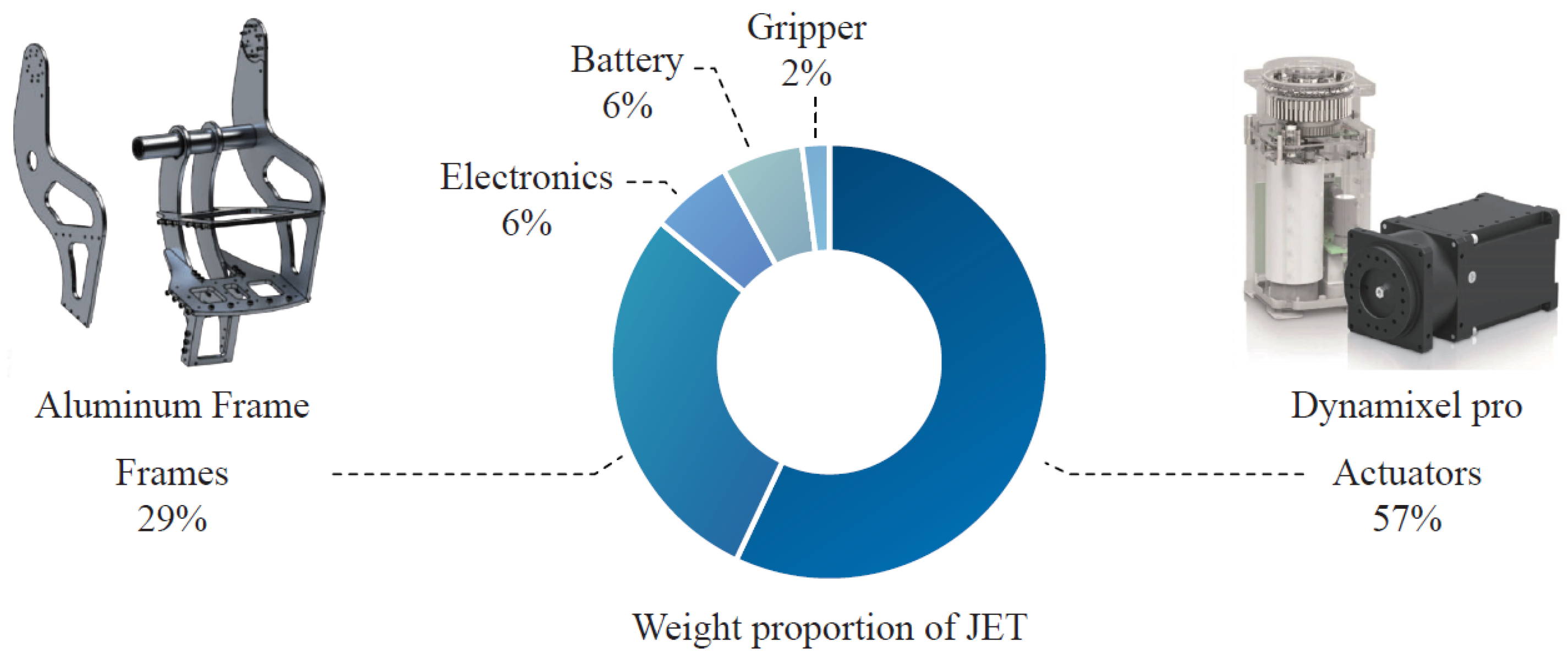
Figure 8 shows the overall weight proportions of each JET component. The actuators occupy more than 50% of the total robot weight. As the ratio of the actuators to the total weight is significant, the actuator arrangement played an important role in load reduction. In various studies, four bar linkages or ball screws have been used to position the actuators close to the first limb joint [27,28]. Although transmission helps reduce inertia, these approaches increase the overall weight and mechanical element number. Such changes would complicate achievement of the design goals in this case.
Therefore, the JET actuators were placed as close as possible to the parent joint. However, a simple structure is maintained. As shown in Figure 9, various actuator arrangements are possible. The JET actuator positions are colored blue, and the worst cases, with maximum inertia, are colored orange. The inertia values at the hip and shoulder calculated for each case are listed in Table 3. Note that all values were calculated from the initial pose, with full extension of the robot legs and arms.
For example, the total inertia of the entire leg at the hip roll joint is 2.53 kgm for the blue case, with a knee-actuator inertia of 0.22 kgm. For the orange case, however, the knee actuator contributes 0.34 kgm to the total inertia with respect to the hip roll joint. Therefore, the inertia due to the knee actuator increases by 50%, and the total inertia increases by 5%. The foot has a major effect on the total inertia. When the robot bends its knees, the proportion of inertia due to the knee actuator increases. Note that the total inertia decreases when the knees bend, but the inertia due to the knee actuator is independent of the joint configuration. Therefore, the proposed design has a greater impact in the walking configuration. Similar to the knee actuator, the forearm and arm actuator positions affect the inertia at the shoulder joint. Without weight reduction, inertia reduction is achieved through actuator rearrangement.
Although each JET link was lengthened, the entire link weight is 3 kg less than that of THORMANG. We designed a frame with polygonal-shaped holes, not only for weight reduction but also to enhance the actuator connector accessibility. The actuator modules were utilized as the frame itself to reduce the weight. Thus, in the final design, most actuator modules are exposed. Hence, most actuators can be easily disassembled and replaced. For safety, every frame was assessed via FEA to confirm a yield strength with a gravity load.
Most frames were designed to have flat plate shapes for cheap fabrication. These flat frames were manufactured by laser cutting, which is faster and cheaper than CNC milling. Sanding is essential for laser cut frames to remove the roughness of the laser cut surface. However, both rough and sanded surfaces are too inaccurate for assembly. Therefore, we designed flat frames that do not require high edge tolerance for assembly. This design approach allowed us to manufacture complex links, such as the thigh links in Figure 5b, at low cost.
To reduce the total weight, the battery capacity was reduced from 44,000 to 22,000 mAh. THORMANG utilizes two low-performance computers. However, JET features one high-performance computer. Additionally, for weight reduction, JET has no bumpers. Therefore, the total JET weight is 12 kg lower than that of THORMANG.
3.5. Design for Maintenance
Section 3.1, Section 3.3 and Section 3.4 describe the electric connector frame design and unification. In addition to the above design approaches, the number of bolt types used for assembly was also limited. Dynamixel Pro requires M3 bolts. Thus, many of the bolts for the frames were selected to have an M3 size. Overall, more than 95% of the bolts in the finalized design are M3. Further, more than 90% of the bolts are the same size, with one of three different lengths: 6, 8 and, 12 mm. Thus, only one tool is required to disassemble most of the actuators.
4. Performance Demonstrations
This section reports and discusses several experiments performed to demonstrate the performance of the developed hardware. In particular, to assess the compliance and whole-body motion capability, various tests involving locomotion, stair climbing, exiting a vehicle, etc., were performed.
As mentioned in Section 1, compliance reduces physical damage or instability from unexpected contacts. Therefore, compliance helps increase robot stability and balance during contact situations. However, compliance from low-stiffness actuators in the supporting limb often causes problems during humanoid bipedal walking, which degrades the performance and stability. To overcome this problem, in a previous work, we presented the actuator elasticity compensator [16].
To enhance the swing leg compliance and overcome the negative features of the supporting leg, the following studies were conducted. External joint encoders were installed to measure the actuator deformation [23]. A linear quadratic regulator (LQR)-based trajectory tracking controller and disturbance observer (DOB)-based compliance controller, which were presented in our previous work [29], were also employed, along with a walking pattern generator with improved stability proposed by Kim et al. [30]. Using these new algorithms, JET can walk faster and with better stability than THORMANG. To minimize the COM velocity fluctuation, model predictive control-based pattern generation was developed and verified for JET [31].
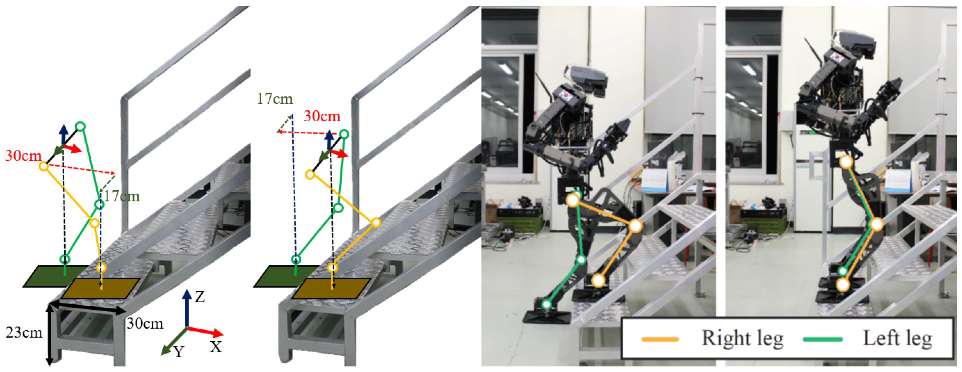
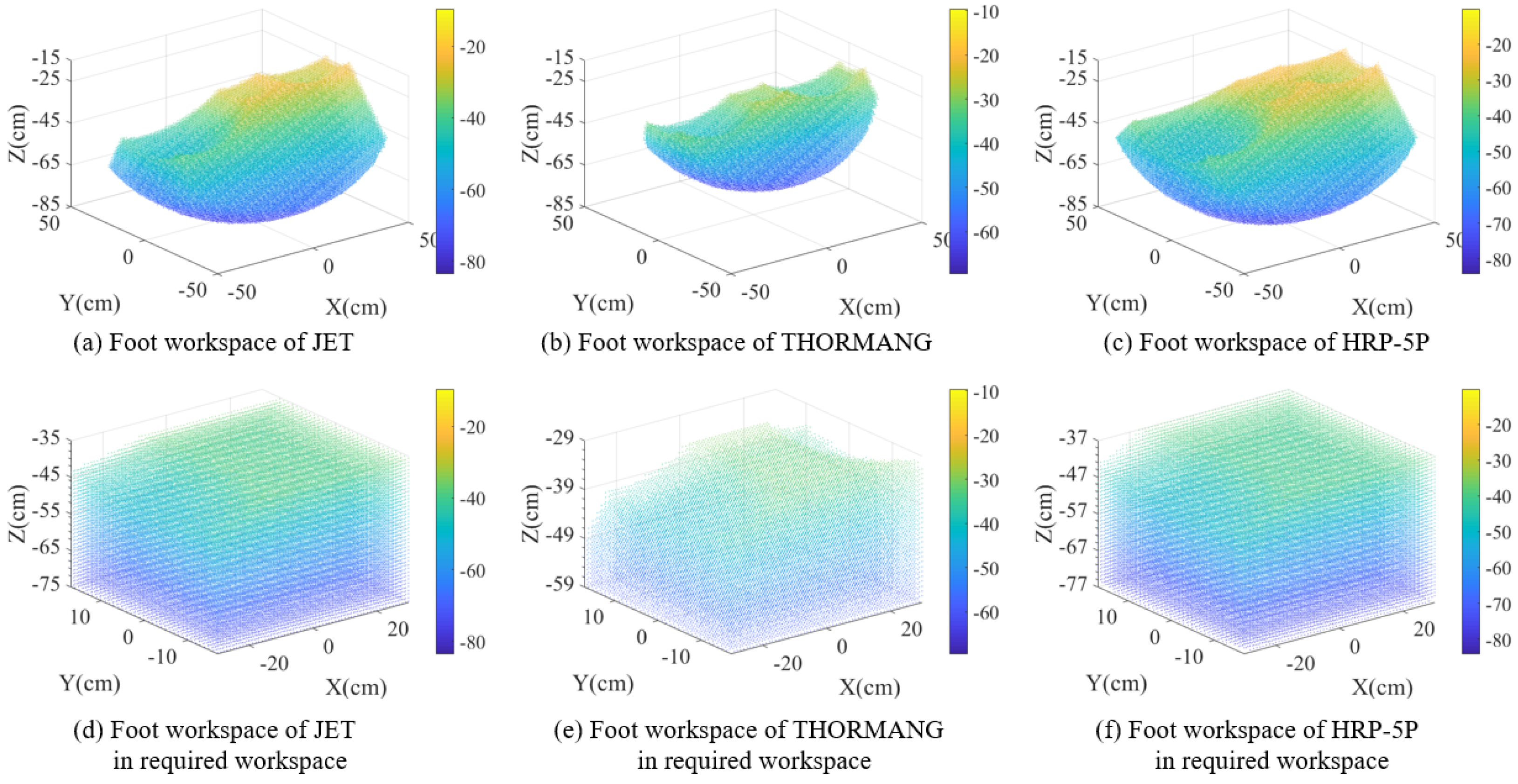
Whole-body motion capability was verified through the following experiments. Stair climbing and egress experiments were chosen among the DRC Finals missions. Both tasks were the hardest tasks in the DRC Finals because THORMANG has short legs for these missions. First, the lower body workspaces were validated through stair climbing experiments on 23 cm high stairs, which were the same height as the stairs used in the DRC Finals. As shown in Figure 10, JET walked up the stairs without any of the THORMANG strategies applied at the DRC. That is, THORMANG climbed the stairs without bumping into the stairs themselves by grabbing the rails and walking backwards [11]. The required foot workspaces of the JET for climbing stairs are cm for x-axis, cm for y-axis, and 23 cm for z-axis as shown in Figure 10. The x and z axis workspaces are determined by the dimensions of the stairs. Figure 11 shows the total foot workspace of JET, THORMANG, and HRP-5P and the required workspaces of the robots. In Figure 11d, JET has a 32 cm z-axis workspace from −75 cm to −43 cm. In the same way, HRP-5P has a 34 cm z-direction workspace from −77 cm to −43 cm, but THORMANG has only a 17 cm z-direction workspace from −59 cm to −42 cm. In this experiment, JET used the same walking pattern generation algorithm which was used at the DRC Finals [11].
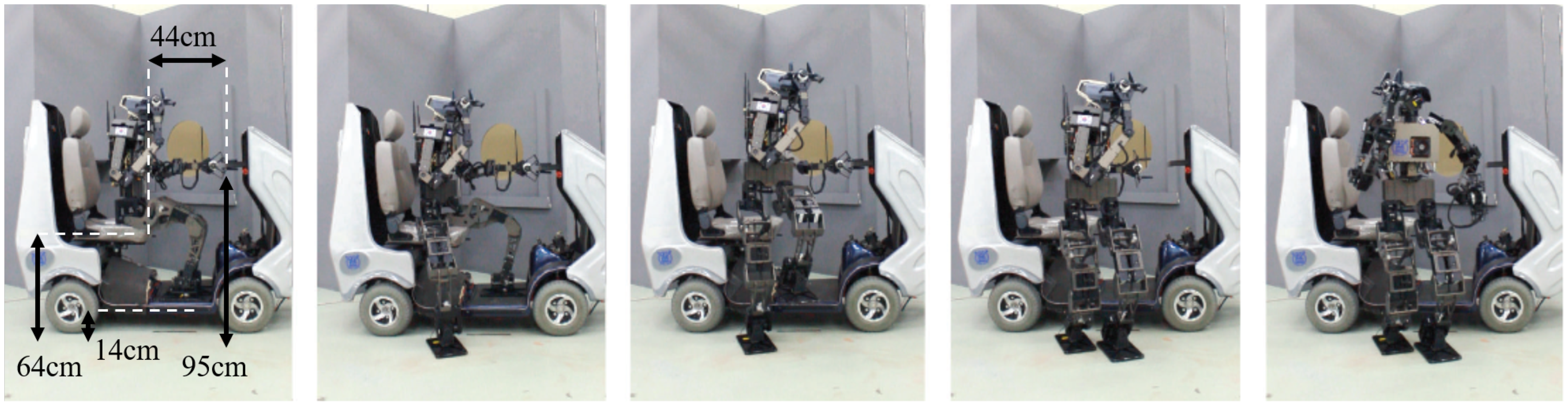
Next, we confirmed the robot could rise from a 64 cm high vehicle seat using whole-body motion with multiple contacts. Figure 12 shows snapshots of the robot egress from the vehicle. In this experiment, the robot performed whole-body motion with contacts at the gripper, pelvis, and two feet. The gripper holds the hand rail to stabilize the body during the JET stand-up. This demonstrated not only the improved robot workspaces, but also the robot’s capability to execute compliant motion in multiple-contact situations. In this experiment, the personal mobility vehicle which was designed for adults is used. The height of the vehicle seat is 56 mm, which is shorter than the fully stretched leg length of THORMANG.
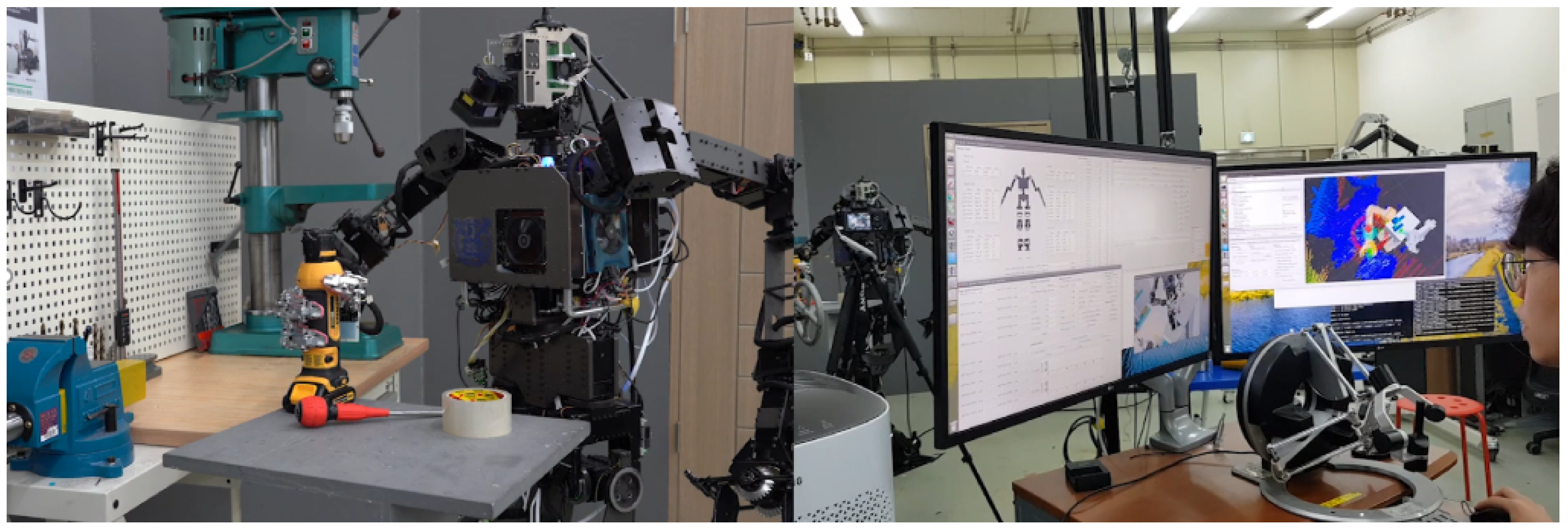
In Figure 13, JET manipulated objects with the gripper developed by Kim and Park and teleoperation systems [32]. Videos of experiments on manipulation and locomotion can be viewed at https://youtu.be/jWbCwT1IYJ4 (accessed on 1 July 2021), https://youtu.be/T48uXPhgeoU (accessed on 1 July 2021), and https://youtu.be/ZfyvAklrUBQ (accessed on 1 July 2021).
5. Conclusions
We developed the JET humanoid robot, which is based on the THORMANG platform. To develop JET, the limitations of THORMANG were considered, as revealed by our experiences at the DRC. However, THORMANG has the advantage of easy maintenance as it employs the Dynamixel commercial modular actuator. To retain the advantages of THORMANG but overcome its platform limitations, three design goals were identified with the aim of effective application to the industrial and service fields: compliance, whole-body motion capability, and easy maintenance. To achieve compliance, the Dynamixel low stiffness was utilized to achieve compliance with external environments.
To overcome the small workspaces of THORMANG, the overall height was increased. However, the weight and inertia were reduced to satisfy the power requirement. Notably, load alleviation is essential for a taller robot with the same actuators. The leg-joint ROM was also increased to achieve a larger lower limb workspace.
Both manufacturing and maintenance methods were considered for the JET design. The frame was designed to provide easy access to the electronics, including the computer, power modules, and actuators. With this exposed design, the modular actuators can be replaced easily. Further, by limiting the number of electric connector and bolt types, the number of parts required for actuator replacement was reduced. The number of links requiring manufacture with expensive CNC milling was reduced through the use of flat-plate-shaped links, which can be manufactured through low-cost laser cutting.
Several experiments were conducted to verify the enhancements of the JET humanoid robot based on the above three design concepts. Compliance and enhanced whole-body motion capability were observed for stair climbing and egress from a personal mobile vehicle. In addition, the entire system was verified through a teleoperation test. These experiments validated the JET performance.
As a future study, an optimization-based control and path generation algorithm to improve walking speed and stability will be developed based on the JET proposed in this paper.
Author Contributions
Conceptualization, methodology, formal analysis, J.S. and S.K. (Seungyeon Kim); software, S.P., M.K. and S.K. (Sanghyun Kim); validation, M.K. and S.K. (Sanghyun Kim); investigation, J.S., S.K. (Seungyeon Kim) and M.K.; resources, J.S.; data curation, J.S.; writing—original draft preparation, J.S., S.K. (Seungyeon Kim) and S.K. (Sanghyun Kim); writing—review and editing, J.S.; visualization, S.K. (Seungyeon Kim); supervision, J.P.; project administration, J.P.; funding acquisition, J.P. All authors have read and agreed to the published version of the manuscript.
Funding
This work was supported by a National Research Foundation of Korea (NRF) grant funded by the Korean government (MSIT) (No. 2021R1A2C3005914).
Conflicts of Interest
The authors declare no conflict of interest.
Abbreviations
The following abbreviations are used in this manuscript:
| ROM | Range of Motion |
| DRC | DARPA Robotics Challenge |
| SEA | Series Elastic Actuator |
| DOF | Degree of Freedom |
| FEA | Finite Element Analysis |
| CNC | Computerized Numerical Control |
References
- Krotkov, E.; Hackett, D.; Jackel, L.; Perschbacher, M.; Pippine, J.; Strauss, J.; Pratt, G.; Orlowski, C. The DARPA Robotics Challenge Finals: Results and Perspectives. J. Field Robot. 2016, 34, 229–240. [Google Scholar] [CrossRef]
- Caron, S.; Kheddar, A. Multi-contact walking pattern generation based on model preview control of 3D COM accelerations. In Proceedings of the 16th International Conference on Humanoid Robots (Humanoids) IEEE-RAS, Cancun, Mexico, 15–17 November 2016; pp. 550–557. [Google Scholar]
- Negrello, F.; Garabini, M.; Catalano, M.G.; Kryczka, P.; Choi, W.; Caldwell, D.G.; Bicchi, A.; Tsagarakis, N.G. WALK-MAN humanoid lower body design optimization for enhanced physical performance. In Proceedings of the International Conference on Robotics and Automation (ICRA), Stockholm, Sweden, 16–21 May 2016; pp. 1817–1824. [Google Scholar]
- Dietrich, A.; Wimböck, T.; Albu-Schäffer, A. Dynamic whole-body mobile manipulation with a torque controlled humanoid robot via impedance control laws. In Proceedings of the 2011 IEEE/RSJ International Conference on Intelligent Robots and Systems, San Francisco, CA, USA, 25–30 September 2011; pp. 3199–3206. [Google Scholar]
- Sands, T. Optimization Provenance of Whiplash Compensation for Flexible Space Robotics. Aerospace 2019, 6, 93. [Google Scholar] [CrossRef] [Green Version]
- Ren, T.; Dong, Y.; Wu, D.; Chen, K. Learning-based variable compliance control for robotic assembly. J. Mech. Robot. 2018, 10. [Google Scholar] [CrossRef]
- Paine, N.; Mehling, J.S.; Holley, J.; Radford, N.A.; Johnson, G.; Fok, C.L.; Sentis, L. Actuator Control for the NASA-JSC Valkyrie Humanoid Robot: A Decoupled Dynamics Approach for Torque Control of Series Elastic Robots. J. Field Robot. 2015, 32, 378–396. [Google Scholar] [CrossRef]
- Knabe, C.; Griffin, R.; Burton, J.; Cantor-Cooke, G.; Dantanarayana, L.; Day, G.; Ebeling-Koning, O.; Hahn, E.; Hopkins, M.; Neal, J.; et al. Team valor’s escher: A novel electromechanical biped for the darpa robotics challenge. J. Field Robot. 2017, 34, 912–939. [Google Scholar] [CrossRef]
- DeDonato, M.; Polido, F.; Knoedler, K.; Babu, B.P.; Banerjee, N.; Bove, C.P.; Cui, X.; Du, R.; Franklin, P.; Graff, J.P.; et al. Team WPI-CMU: Achieving Reliable Humanoid Behavior in the DARPA Robotics Challenge. J. Field Robot. 2017, 34, 381–399. [Google Scholar] [CrossRef]
- Stentz, A.; Herman, H.; Kelly, A.; Meyhofer, E.; Haynes, G.C.; Stager, D.; Zajac, B.; Bagnell, J.A.; Brindza, J.; Dellin, C.; et al. Chimp, the cmu highly intelligent mobile platform. J. Field Robot. 2015, 32, 209–228. [Google Scholar] [CrossRef]
- Kim, S.; Kim, M.; Lee, J.; Hwang, S.; Chae, J.; Park, B.; Cho, H.; Sim, J.; Jung, J.; Lee, H.; et al. Team SNU’s Control Strategies for Enhancing a Robot’s Capability: Lessons from the 2015 DARPA Robotics Challenge Finals. J. Field Robot. 2016, 34, 359–380. [Google Scholar] [CrossRef]
- SHG-17-100-2SO | Harmonic Drive. Available online: https://www.harmonicdrive.net/products/gear-units/simplicity-gear-units/shg-2so/shg-17-100-2so (accessed on 11 June 2021).
- Robotis e-Manual. Available online: https://emanual.robotis.com/docs/en/dxl/pro/h54-200-s500-ra/ (accessed on 11 June 2021).
- Tsagarakis, N.G.; Caldwell, D.G.; Negrello, F.; Choi, W.; Baccelliere, L.; Loc, V.G.; Noorden, J.; Muratore, L.; Margan, A.; Cardellino, A.; et al. Walk-man: A high-performance humanoid platform for realistic environments. J. Field Robot. 2017, 34, 1225–1259. [Google Scholar] [CrossRef]
- Tsagarakis, N.G.; Morfey, S.; Cerda, G.M.; Zhibin, L.; Caldwell, D.G. Compliant humanoid coman: Optimal joint stiffness tuning for modal frequency control. In Proceedings of the 2013 IEEE International Conference on Robotics and Automation (ICRA), Karlsruhe, Germany, 6–10 May 2013; pp. 673–678. [Google Scholar]
- Kim, J.; Kim, M.; Park, J. Improvement of humanoid walking control by compensating actuator elasticity. In Proceedings of the 2016 IEEE-RAS 16th International Conference on Humanoid Robots (Humanoids), Cancun, Mexico, 15–17 November 2016; pp. 29–34. [Google Scholar]
- Kim, S.; Kim, M.; Lee, J.; Hwang, S.; Chae, J.; Park, B.; Cho, H.; Sim, J.; Jung, J.; Lee, H.; et al. Approach of team snu to the darpa robotics challenge finals. In Proceedings of the 2015 IEEE-RAS 15th International Conference on Humanoid Robots (Humanoids), Seoul, Korea, 3–5 November 2015; pp. 777–784. [Google Scholar]
- Stasse, O.; Flayols, T.; Budhiraja, R.; Giraud-Esclasse, K.; Carpentier, J.; Mirabel, J.; Del Prete, A.; Souères, P.; Mansard, N.; Lamiraux, F.; et al. TALOS: A new humanoid research platform targeted for industrial applications. In Proceedings of the 2017 IEEE-RAS 17th International Conference on Humanoid Robotics (Humanoids), Birmingham, UK, 15–17 November 2017; pp. 689–695. [Google Scholar]
- Korean Size Report. Available online: Https://sizekorea.kr/ (accessed on 7 May 2021).
- Talos Description. Available online: https://github.com/pal-robotics/talos_robottree/kinetic-devel/talos_description (accessed on 11 June 2021).
- Kaneko, K.; Kaminaga, H.; Sakaguchi, T.; Kajita, S.; Morisawa, M.; Kumagai, I.; Kanehiro, F. Humanoid robot HRP-5P: An electrically actuated humanoid robot with high-power and wide-range joints. IEEE Robot. Autom. Lett. 2019, 4, 1431–1438. [Google Scholar] [CrossRef]
- Ogura, Y.; Aikawa, H.; Shimomura, K.; Morishima, A.; Lim, H.O.; Takanishi, A. Development of a new humanoid robot WABIAN-2. In Proceedings of the 2006 IEEE International Conference on Robotics and Automation, ICRA 2006, Orlando, FL, USA, 15–19 May 2006; pp. 76–81. [Google Scholar]
- Park, S.; Sim, J.; Park, J. System design of humanoid robot dyros-jet. In Proceedings of the 2019 IEEE/SICE International Symposium on System Integration (SII), Paris, France, 14–16 January 2019; pp. 746–750. [Google Scholar]
- Kojima, K.; Kojio, Y.; Ishikawa, T.; Sugai, F.; Kakiuchi, Y.; Okada, K.; Inaba, M. A robot design method for weight saving aimed at dynamic motions: Design of humanoid JAXON3-P and realization of jump motions. In Proceedings of the 2019 IEEE-RAS 19th International Conference on Humanoid Robots (Humanoids), Toronto, ON, Canada, 15–17 October 2019; pp. 586–593. [Google Scholar]
- Ogura, Y.; Lim, H.O.; Takanishi, A. Stretch walking pattern generation for a biped humanoid robot. In Proceedings of the 2003 IEEE/RSJ International Conference on Intelligent Robots and Systems, 2003 (IROS 2003), Las Vegas, NV, USA, 27–31 October 2003; Volume 1, pp. 352–357. [Google Scholar]
- Lim, J.; Lee, I.; Shim, I.; Jung, H.; Joe, H.M.; Bae, H.; Sim, O.; Oh, J.; Jung, T.; Shin, S.; et al. Robot System of DRC-HUBO+ and Control Strategy of Team KAIST in DARPA Robotics Challenge Finals. J. Field Robot. 2017, 34, 802–829. [Google Scholar] [CrossRef]
- Lohmeier, S.; Buschmann, T.; Schwienbacher, M.; Ulbrich, H.; Pfeiffer, F. Leg design for a humanoid walking robot. In Proceedings of the 2006 6th IEEE-RAS International Conference on Humanoid Robots, Genova, Italy, 4–6 December 2006; pp. 536–541. [Google Scholar]
- Lahr, D.F. Design and Control of a Bipedal Robot. Ph.D. Thesis, Virginia Polytechnic Institute and State University, Blacksburg, VA, USA, 2014. [Google Scholar]
- Kim, M.; Kim, J.H.; Kim, S.; Sim, J.; Park, J. Disturbance observer based linear feedback controller for compliant motion of humanoid robot. In Proceedings of the 2018 IEEE International Conference on Robotics and Automation (ICRA), Brisbane, QLD, Australia, 21–25 May 2018; pp. 403–410. [Google Scholar]
- Kim, M.; Lim, D.; Park, J. Online walking pattern generation for humanoid robot with compliant motion control. In Proceedings of the 2019 International Conference on Robotics and Automation (ICRA), Montreal, QC, Canada, 20–24 May 2019; pp. 1417–1422. [Google Scholar]
- Park, B.; Park, J. Walking Pattern Generation using MPC with minimization of COM Velocity Fluctuation. In Proceedings of the 2020 20th International Conference on Control, Automation and Systems (ICCAS), Busan, Korea, 13–16 October 2020; pp. 268–273. [Google Scholar]
- Kim, S.; Park, J. Gripper with Thumb Adduction/Abduction Joint for Enhanced In-hand Orientation Manipulation. In Proceedings of the 2018 IEEE-RAS 18th International Conference on Humanoid Robots (Humanoids), Beijing, China, 6–9 November 2018; pp. 1–9. [Google Scholar]
Figure 1.
Humanoid robot JET.

Figure 2.
THORMANG platform at DRC Finals in 2015: (a) THORMANG, TEAM SNU (1.47 m, 60 kg), (b) THOR-RD, TEAM THOR (1.50 m, 54 kg), (c) Johnny05, TEAM Hector (1.47 m, 55 kg), (d) THORMANG2, TEAM ROBOTIS (1.60 m, 60 kg).
Figure 2.
THORMANG platform at DRC Finals in 2015: (a) THORMANG, TEAM SNU (1.47 m, 60 kg), (b) THOR-RD, TEAM THOR (1.50 m, 54 kg), (c) Johnny05, TEAM Hector (1.47 m, 55 kg), (d) THORMANG2, TEAM ROBOTIS (1.60 m, 60 kg).

Figure 3.
Kinematic structure of JET.

Figure 4.
Electrical system diagram of JET.

Figure 5.
Lower limb design: (a) lower body standby posture, (b) thigh design, (c) lower body squatting pose. The lower body frames were designed to avoid self-collisions. In particular, the thigh frames were designed such that the link front surfaces are perpendicular to the ground.
Figure 5.
Lower limb design: (a) lower body standby posture, (b) thigh design, (c) lower body squatting pose. The lower body frames were designed to avoid self-collisions. In particular, the thigh frames were designed such that the link front surfaces are perpendicular to the ground.

Figure 6.
ROM comparison for JET, THORMANG, THORMANG3, TALOS, HRP-5P, and JAXON3-P hip joints.

Figure 7.
Exploded view of computer module. The modularized computer board can be sideways-disassembled by removing four bolts.
Figure 7.
Exploded view of computer module. The modularized computer board can be sideways-disassembled by removing four bolts.

Figure 8.
JET weight proportions.

Figure 9.
Possible actuator arrangements, blue for JET and orange for bad case: (a) Knee actuator arrangements, (b) Forearm actuator arrangements, (c) Arm actuator arrangements.
Figure 9.
Possible actuator arrangements, blue for JET and orange for bad case: (a) Knee actuator arrangements, (b) Forearm actuator arrangements, (c) Arm actuator arrangements.

Figure 10.
Snapshots of stair climbing test.

Figure 11.
Comparison of foot workspace among JET, THORMANG, and HRP-5P. (a–c) are the total foot workspaces of JET, THORMANG, and HRP-5P. (d–f) are the required workspaces with 60 cm × 34 cm on x- and y-axis.
Figure 11.
Comparison of foot workspace among JET, THORMANG, and HRP-5P. (a–c) are the total foot workspaces of JET, THORMANG, and HRP-5P. (d–f) are the required workspaces with 60 cm × 34 cm on x- and y-axis.

Figure 12.
Snapshots of egress test with personal mobility. Videos can be seen at https://youtu.be/6NWdPNTjnjs (accessed on 1 July 2021).
Figure 12.
Snapshots of egress test with personal mobility. Videos can be seen at https://youtu.be/6NWdPNTjnjs (accessed on 1 July 2021).

Figure 13.
Manipulating objects with teleoperation.


Table 1.
Scores of THORMANG-based teams in DRC Finals. Team SNU successfully performed 4 missions (O), but failed 4 missions (X), including the egress task.
Table 1.
Scores of THORMANG-based teams in DRC Finals. Team SNU successfully performed 4 missions (O), but failed 4 missions (X), including the egress task.
| Mission | Team SNU | Team ROBOTIS | Team THOR | Team HECTOR |
|---|---|---|---|---|
| Driving | O | O | O | O |
| Egress | X | X | X | X |
| Door | O | O | O | X |
| Valve | O | O | O | X |
| Wall | O | X | X | X |
| Surprise | X | X | X | X |
| Rubble | X | X | X | X |
| Stairs | X | X | X | X |
| Score | 4 | 3 | 3 | 1 |
Table 2.
Comparison of JET, THORMANG (Team SNU), THORMANG3, TALOS, HRP-5P, and average Korean young female (aged 20–24) characteristics.
Table 2.
Comparison of JET, THORMANG (Team SNU), THORMANG3, TALOS, HRP-5P, and average Korean young female (aged 20–24) characteristics.
| JET | THORMANG (Team SNU) | THORMANG3 | TALOS [20] | HRP-5P [21] | Korean Young Female | |
|---|---|---|---|---|---|---|
| Height (m) | 1.63 | 1.47 | 1.38 | 1.75 | 1.83 | 1.61 |
| Weight (kg) | 48 | 60 | 42 | 95 | 101 | 55 |
| Wingspan (m) | 2.12 | 1.95 | 1.69 | 2.1 | - | 1.62 |
| Leg length (mm) | 839 | 696 | 716 | 837 | 862 | 799 |
| Thigh length (mm) | 370 | 300 | 300 | 380 | 380 | 384 |
| Shin length (mm) | 373 | 300 | 300 | 325 | 380 | 352 |
| Foot height (mm) | 96 | 96 | 116 | 132 | 102 | 63 |
| Degree of freedom | 32 | 32 | 32 | 31 | 37 | - |
Table 3.
Comparison of inertia values for various actuators and arrangements.
| Joint Inertia | Joint Inertia | |
|---|---|---|
| for Blue Case | for Orange Case | |
| (Total/Actuator) | (Total/Actuator) | |
| Hip roll | ||
| (Knee actuator) | 2.53/0.22 | 2.65/0.34 |
| Hip pitch | ||
| (Knee actuator) | 2.53/0.22 | 2.65/0.34 |
| Shoulder pitch | ||
| (forearm actuator) | 1.13/0.08 | 1.26/0.20 |
| Shoulder pitch | ||
| (arm actuator) | 1.13/0.02 | 1.26/0.03 |
| Shoulder roll | ||
| (forearm actuator) | 1.15/0.08 | 1.29/0.20 |
| Shoulder roll | ||
| (arm actuator) | 1.15/0.02 | 1.29/0.03 |
Publisher’s Note: MDPI stays neutral with regard to jurisdictional claims in published maps and institutional affiliations. |
© 2021 by the authors. Licensee MDPI, Basel, Switzerland. This article is an open access article distributed under the terms and conditions of the Creative Commons Attribution (CC BY) license (https://creativecommons.org/licenses/by/4.0/).
Share and Cite
MDPI and ACS Style
Sim, J.; Kim, S.; Park, S.; Kim, S.; Kim, M.; Park, J. Design of JET Humanoid Robot with Compliant Modular Actuators for Industrial and Service Applications. Appl. Sci. 2021, 11, 6152. https://doi.org/10.3390/app11136152
AMA Style
Sim J, Kim S, Park S, Kim S, Kim M, Park J. Design of JET Humanoid Robot with Compliant Modular Actuators for Industrial and Service Applications. Applied Sciences. 2021; 11(13):6152. https://doi.org/10.3390/app11136152
Chicago/Turabian StyleSim, Jaehoon, Seungyeon Kim, Suhan Park, Sanghyun Kim, Mingon Kim, and Jaeheung Park. 2021. "Design of JET Humanoid Robot with Compliant Modular Actuators for Industrial and Service Applications" Applied Sciences 11, no. 13: 6152. https://doi.org/10.3390/app11136152
Note that from the first issue of 2016, this journal uses article numbers instead of page numbers. See further details here.