
Methodological and On-Site Applied Construction Layout Plan with Batter Boards Stake-Out Methods Comparison: A Case Study of Romania


Faculty of Civil Engineering, Technical University of Cluj-Napoca, 400020 Cluj-Napoca, Romania
Appl. Sci. 2021, 11(10), 4331; https://doi.org/10.3390/app11104331
Submission received: 21 April 2021
/
Revised: 8 May 2021
/
Accepted: 10 May 2021
/
Published: 11 May 2021
(This article belongs to the Special Issue Technology and Management Applied in Construction Engineering Projects)
Abstract
:The layout or stake-out is one of the most important assignments of the surveying engineer, and it is of vital importance in the building process, as the designed geometries of the structure ensure the verticality and the correct positioning inside the terrain. The mission of the surveying engineer involves both legal and technical aspects, and the correct planning of the layout process must take into consideration aspects regarding the site conditions, instrumentation used, the required and achievable accuracies, network design and survey methods used. Given the vast applications of geodesy and topography in different domains and industries, the study incorporates general notions and technical aspects regarding the workflow in cadastre and construction surveying, guidelines for an efficient design of site layout plan with on-site applicability, as well as a novel comparison between four methods of construction lines geometry layout on batter boards. The results of this study aim to further consolidate the importance of accurate and efficient construction layout projects, with comprehensive design plans, methods and instrumentation selection, as well as recommendations. The presented discussions and conclusions are of interest to the geodetic community as well as the construction industry, and due to the pragmatic and experimental nature of the research, incorporates technical notes and original results of professional and academic importance.
1. Introduction
The efficient layout planning of a construction site is a fundamental task for any project undertaking, and the survey engineer’s responsibility to guide the builders and conduct accurate, safe, time- and cost-efficient layout of the designed structure [1,2,3]. In theory, any surveyor can attempt a construction survey or precision surveying project. However, due to the difficulties of the work and the unpredictable site conditions and scenarios, the practice is much more difficult than would be expected. While the principals involved in surveying are generally established, the instrumentation used is equally important and the survey engineer must adapt and be prepared for any situation and task [4,5]. Thus, this research attempts to give answers to the following notions: the surveyor engineer’s workflow and each legal and technical stage involved in a construction project, the design of a comprehensive site layout plan with on-site applicability and a comparison between four methods of construction lines layout on batter boards.
It is critical for a surveyor to take the time and care, both in the field and when processing data, to avoid or minimize errors and conduct precise and efficient surveys, layout or monitoring projects [5,6]. These applications and tasks integrate the highly sophisticated graphical capabilities of computer-aided design (CAD) platforms, with the geodetic instrumentations used in the field for observations and data collection. Precision surveyors working in the field have a large array of instrumentation at their disposition, with a constant flux of innovation [7,8,9]. There are numerous instrumentations and technologies used in the industry, such as: total stations, optical and digital levels, GNSS (Global Navigation Satellite System), terrestrial laser scanners, UAV (unmanned aerial vehicle) photogrammetry, airborne or UAV light detection and ranging (LiDAR), and many more geomatics applications. Each one of the instrumentations and techniques have certain advantages or disadvantages, that range from cost, to survey coverage, time efficiency, precision, and learning curve. Although for survey and monitoring projects all of the aforementioned instrumentation can provide viable solutions, in the case of layout projects and precise construction surveying, total stations are the best choice. Total stations have pinpoint accuracy and can yield precise surveying, positioning and observations [10,11,12]. In spite of the increasing use of new technologies, total stations remain a fundamental instrument for different survey projects, including land, cadastre and especially constructions [13].
Due to the many variables that encroach on the physical world and on the construction sites, surveyors must be extremely cautious with the work management, instrumentation used, data processing and error mitigations [14,15,16]. In field applications, precision surveying, layout and monitoring projects are used to provide cost savings, offer guidance and expertise to builders, verify design assumptions, reduce risks and even to protect lives [17,18,19]. Although in theory these are simple and easy benefits to obtain, due to the practical and somehow unpredictable nature of the profession, in practice these benefits may be difficult to obtain due to different site conditions, access problems or budgetary constraints. Thus, the present research serves as a combination of technical notes in the field of geodesy and topography applied in construction, guidelines for efficient layout plan design and on-site implementation, and a pragmatic and experimental comparison for the layout of a construction geometry on batter boards. The results of this study are of interest to the geodetic community as well as the construction industry, for many surveying engineering and land surveying applications. In addition, they can be instructive from an educational point of view, as well as beneficial to the private sector, public sector and academia.
2. Materials and Methods
2.1. Land Surveyor Profession in Romania
Surveying engineers are people who work both in the field taking measurements, as well as in the office, analyzing the measured data and planning maps, technical plans and registering legal documents regarding boundaries of existing land parcels. It is often said that surveyor engineers are the first persons to enter the construction site, and the last to leave it. This is because the inception of any investment construction project starts from the legal documents regarding the location, as well as feasibility studies that involve topographic surveys in order to provide geo-spatial data to the architects, civil engineers and other design engineers.
In Romania, the profession of survey engineering is called topographer or geodetic engineer. Compared to other countries, in Romania this profession combines the knowledge, attributions and responsibility of both land surveyors and building surveyors. In essence, a Romanian topographer or geodetic engineer is the person who consults and works with the legal aspects of property law, such as boundary surveys and cadastre, as well as the technical aspects that involve the construction industry, such as guiding the construction of new structures such as infrastructures or buildings.
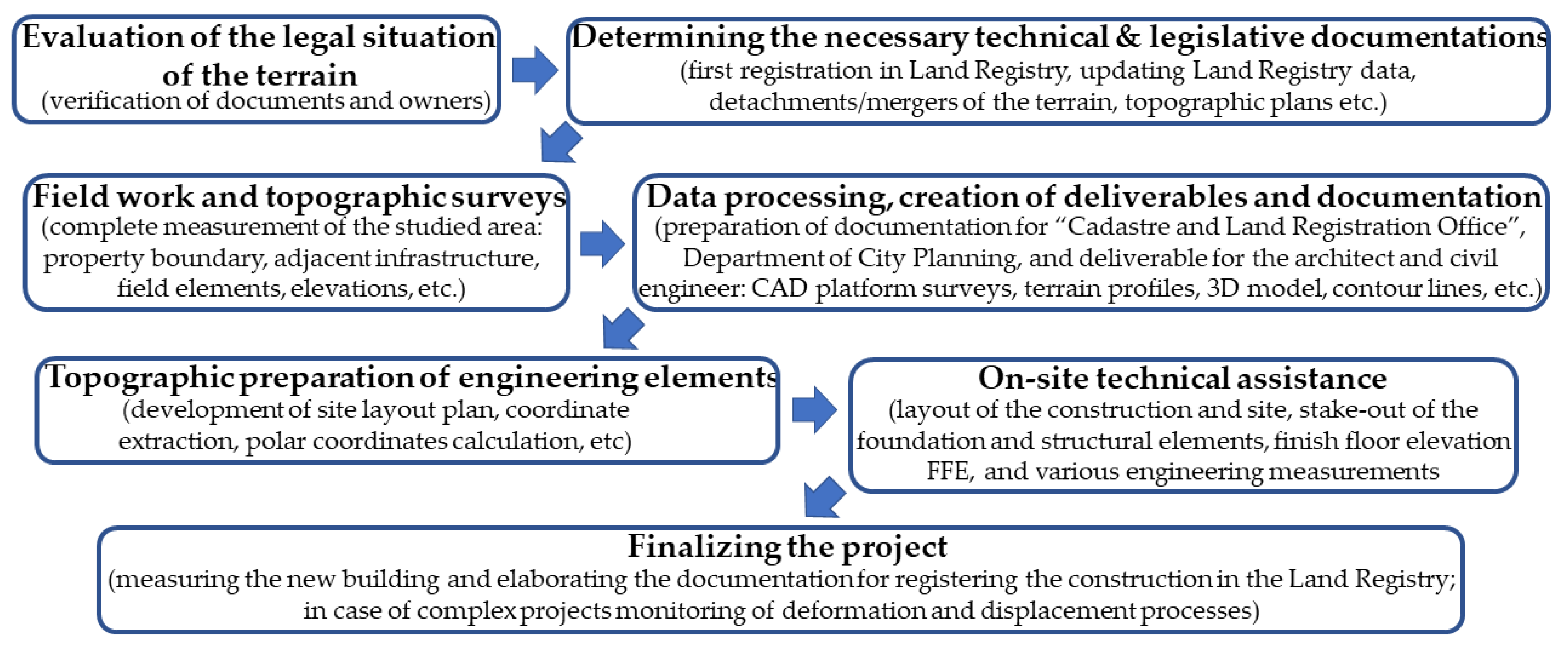
In order to practice this profession, a bachelor’s degree is required, as well as a number of years of experience in order to become an authorized or licensed surveyor, with one of the four different levels of qualification: C, B, A and D (highest). These levels of qualification require different years of experience, portfolio of survey works and different types of examination and interviews. As a license to practice, a category C surveyor can only work in cadastre and land surveys, categories B and A, beside the previous category C competencies, can design technical topographical plans, building surveys, layout or stake-out of reference points and markers for constructions and, lastly category D, which incorporates the previous competencies, can also create or verify geodetic networks. The authority that grants these licenses to practice is the National Agency for Cadastre and Land Registration, a government institution that oversees the property law and cadastre in the country. A typical workflow for a survey engineer is as follows (Figure 1):
The preliminary work consists of consultancy and evaluation of the legal situation of the terrain, as for any building permit it is necessary to have a clear property law, checking property boundaries and assigning a cadastral number. In order to prepare the terrain for investment, besides the land registry data integrity, the shape of the terrain has to be considered, thus there is often documentation for land parcel detachments or mergers. The topographic plan is necessary for both the technical documentation for obtaining the building permit, as well as for the design of the architect and civil engineer, by providing a series of complex works and deliverables such as: computer-aided design (CAD) platform surveys, transverse and longitudinal terrain profiles, 3D modeling of the terrain, contour lines and other elements that are the basis for the architecture, structure and design projects. Works during the construction process include regular site topographic assistance, where the surveyor engineer ensures the connection between the design made by the architect/civil engineer and the builder/contractor. In order to ensure the accuracy of the site position of the designed structural elements, it is necessary to layout or stake-out building reference points as well as construction axes and geometry, markers of finish floor elevations, verifications of various elements and elevations, verticality studies, quantity calculation, monitoring of adjacent buildings and other engineering measurements. Works after completion of constructions include: “As-Built” plan necessary to detect non-conformities between what was built and the project; topographic plans and cadastral works in order to connect the new constructions to utilities and registration in property law; in the case of apartment buildings additional detachment documentations and surveys of interior spaces; and, finally, in the case of complex projects, monitoring of the new building in order to determine its behavior during the period of construction.
2.2. Site Location and Conditions
In the constant expanding and highly populated Cluj-Napoca metropolitan area, Romania (Figure 2), the need for qualitative, safe, time and cost-efficient survey engineering works is imperative. With a general move towards urbanization, the construction industry is booming, land is becoming an increasingly difficult resource to obtain and the construction market is a desideratum [20,21]. The unprecedented urban sprawl phenomenon imposed the expansion of the city limits and the transformation of adjacent villages, agricultural terrains or old industrial parks from Cluj-Napoca into suburbs and residential complexes [22]. Given the current situation, the surveying engineer is a sought-after specialist who can provide multifunctional services for investors such as legal and technical consultancy regarding property law, initial field measurements for the construction design, and on-site technical assistance, up to the final stages of the investment project. Although most of the big construction companies have their own survey engineers, small and medium firms do not and they rely on contracts of service providers with survey engineering companies or licensed individuals. These issues call for a retrospective look at the main technical assistance that survey engineers provide on the construction site (to stake out reference points and markers that will guide the construction of new structures), as well as guidelines for efficient site layout plan creation and the use of on-site batter boards marked with layout lines for future positioning of construction reference points by the builder/contractor.
The present technical project consists of the construction of 2 duplex houses having four living units, in a newly developed neighborhood consisting mainly of houses on the outskirts of Cluj-Napoca (Figure 2). The terrain has an area of 1147 square meters, the designed duplex houses have a low height regime specific to the region, with ground floor and first floor, and each duplex has a double partition wall between the units, thus having the possibility to be registered in property law as four distinct houses. Each designed unit has a usable area of approximately 120 square meters, 2 parking spaces and a garden of approximately 215 square meters, thus making it a perfect solution for young families.
2.3. Methodological Approach and Instrumentation
The methodological structure pursued to develop the presented study is in accordance with the general line of technical notes and practices in the field. Thus, in the present study, the research direction was divided in two main stages of dissemination: that of evaluating the methodological process of obtaining an efficient site layout plan, with a retrospective look at the design and field-work practiced notions; the second main stage, represents the on-site applied designs, together with a novelty comparison between four methods of batter boards stake-out of the construction layout lines, in order to determine the most qualitative, safe, time and cost-efficient one, as well as highlighting advantages and disadvantages of each method and the possible instrumentation used.
To better understand the workflow of such a project, a graphical abstract of the site layout plan process was created (Figure 3). As previously mentioned, the surveyor engineer’s work starts in the office with evaluating the land registry of the terrain, in order to determine the required technical and legislative documentation. Once this stage is complete, an elaborate field measurement is scheduled, with the necessary presence of the land owners or investors. In this topographic survey, the geodetic engineer can either divide his workflow in measurements for cadastral purposes, technical purposes, or combine both of them. Measurements for cadastral purposes are more straightforward, with an emphasis on the boundaries of the property, checking for inadvertences between the measured area and the one in the documents, and accessibility to the terrain. The measurement for technical purposes is much more complex, and requires the data acquisition necessary to create topographic plans for the building permit, as well as deliverables to the architect, civil engineer and other design engineers. It is the survey engineer’s duty to accurately and in great detail represent the terrain surface, in order to develop an investment project. The required deliverables differ depending on the type of project, but the most common ones are the following: a CAD platform complete survey of the study area, with the cadastre contours layer; a 3D model of the terrain and contour lines, achieved also in CAD software; transversal or longitudinal profiles, which are necessary especially for infrastructure. Based on these deliverables, together with a clear property law of the terrain and the topographic plan signed and sealed from the Office of Cadastre and Land Registration, the architect and civil engineer can apply for the Building Permit at the local Department of City Planning. This operation can take up to 6 months, depending on the complexity of the project and the urbanistic regulation in the proposed area. Once the Building Permit is obtained, and the owners or investors have also contracted a team of builders, the need for the survey engineer is again required. The survey engineer must obtain from the design team the site/location plan, which details the geometry and location of the designed building inside the terrain, as well as dimensions between the layout lines or building axes, and distances from the boundary limits to the construction. Even though the initial survey may have been undertaken within a geodetic datum and dimensions, the design team, especially the architects, work in millimeter units and different design softwares, thus the site/location plan received must be converted into the correct coordinate system (in the current case, Stereographic 1970). This process is undertaken in the preferred software of the survey engineer (customarily AutoCAD), and involves the correct cadastral contour and the functions of scale, move and rotate. The desideratum is the creation of the Site Layout Plan, a comprehensive design that highlights the layout of the proposed construction inside the terrain, together with the coordinates and the stake-out elements of the building reference points (usually axes intersections). The stake-out elements consist of horizontal angles and distances from known geodetic points or control points, together with the instrumentation and layout method used in order to mark the position of the designed building. These horizontal angles and distances can be calculated from the Cartesian coordinates of the control/geodetical points and the designed points of the building, and can be done manually or by spreadsheet software. Total stations have the processing capabilities of instantly calculating these values, but it is recommended to also have them calculated and displayed on the final site layout plan.
In terms of used instrumentation, the total station and GNSS systems are the most used by the survey engineer. GNSS systems are the perfect choice for topographical surveys where the field conditions are optimal (sufficient satellite availability, network RTK services, open field etc.). In recent decades, GNSS systems have been used to obtain geodetic networks or control points, for precise measurements, accurate monitoring processes or construction stake-outs. In the case of classical methods of determining new geodetic points, by means of resection or traverse networks, a current deficiency is the lack of reliable control points or geodetic points, almost completely destroyed in the past decades. The total station is often considered the right hand of the survey engineer, and offers pinpoint accuracy and can yield precise observations, as well as efficient and reliable layout of reference points. The instruments used in this case study were: Leica Viva GS08 Global Navigation Satellite System used in real-time kinematics (RTK) mode for obtaining the control points (St1 and St2) with a horizontal precision between 0.014 m and 0.020 m ensured by online RTK corrections provided by the Romanian Position Determination System (ROMPOS) and the connection to a national permanent GNSS reference station; the total station used was a Leica TS02plus, which has a very good measurement accuracy of angles of 3″ and distances of ±2 mm + 2 ppm.
2.4. Layout of a Project Point and Accuracy Evaluation
Construction layout or stake-out is one of the most important missions of the surveying engineer, with the purpose of ensuring the designed geometries of the engineering structure, by satisfying the required accuracies from the project [2,22,23,24,25]. Although modern GNSS systems have the capability of point stake-out with an accuracy of ≈2 cm in the right conditions, construction surveys and layouts are made using total stations. The principle behind a total station stake-out is the polar coordinates method, which consist of calculating and determining the position of a horizontal angle and a distance from a set of two control points (or geodetic points). The two control points are used for instrument stationing and orientation (or bearing), and all calculations regarding the layout of the construction are made in accordance to the established layout network. It was opted for the GNSS technology for the creation of the layout network, because of the efficiency, the lower cost price, and the short time to perform the measurements. In the case of classical methods of determining new geodetic points, by means of resection or traverse networks, the current great deficiency is the lack of reliable control points or geodetic points, almost completely destroyed in the past decades [13].
The layout elements (horizontal angle and a distance) are calculated using the known coordinates of the layout network and the designed coordinates of the construction, as follows (example for layout point H7; Figure 4):
In order to ensure an accurate and efficient layout of the construction points, a retrospective of the measurement errors, required accuracy and the construction tolerances must be taken into account [2,21,22]. The type of building and the building technology are also important aspects, as the components and structural elements used to construct buildings are often fabricated, assembled or built on site, often by hand, in conditions that may be less than ideal. Errorless measurements are impossible, thus it is mandatory to satisfy the recommended accuracies through the “achieved point standard deviation” which is defined by the product of the errors derived from known point coordinates and the layout measurements. In order to assure the required accuracy, the achieved accuracy must be smaller than the required one. Based on the type of construction and the characteristics of the engineering structure, the required point standard deviation (±μP) should be: μP = ±(1–2) cm for the majority of layout construction projects that use a monobloc structure with build on site structural elements (reinforced concrete); μP = ±(2–5) mm for prefabricated and assembled structural elements; μP = ±(1–2) mm for precise machine guidance and complex structures [2,26,27]. It is the surveying engineer’s mission to identify the required accuracy and plan the layout process in accordance. The achieved accuracy if the resultant of error affecting the measurements of the layout elements, expressed as achieved point standard deviation (±σP), and must satisfy the required accuracy:
The errors concerning the measurements are classified into three major groups: instrumental errors, personal errors and atmospheric errors [28,29,30]. Given the present case study, the length of the observations are short and the measurements are made in optimal conditions, as well as through the expertise of the surveying engineers. Thus, personal and atmospheric errors can be considered insignificant and not taken into consideration. The major instrumental errors can be eliminated or significantly reduced by additional checks and calibrations. Given the fact that the measurements are carried out with a new model of the total station with good specifications, it is possible to satisfy the required accuracies of the layout project by using angle and distance reading with only one face of the instrument. By combining the expertise of the survey engineers, the correct checks and calibrations of the instrument, and by using angle readings that not exceed ±(5–10)cc with layout distances of ±(2–3) mm, the achieved point standard deviation can easily be between σP = ±(5–10) mm, more than enough considering the required point standard deviation (±μP) for the type of construction and building technology of the present case study.
2.5. Designing the Site Layout Plan and Calculating the Stake-Out Elements
The planning of the layout process is one of the most important tasks for the survey engineer. This layout ensures the horizontal and vertical geometries of the engineering structure, and takes into account the instrumentation and the required accuracies previously mentioned. The established site layout plan is compiled using the cumulative cadastral information, land survey, building permit and design plans of the construction. A comprehensive design must highlight the layout of the proposed construction inside the terrain, as well as the inclusion of the coordinates and the calculated layout elements of the building reference points. The stake-out elements consist of horizontal angles and distances from known geodetic points or control points and, although total stations are capable of coordinate geometry calculation (COGO functions), the site layout plan should incorporate these values in order to carry out the on-site project regardless of the instrumentation. This is because many construction companies or construction survey engineers use electronic theodolites such as the Leica Builder series, which are reliable instrumentations that measure angles and distances, but do not have the processing power and the functions of coordinate geometry calculation. Thus, a comprehensive site layout plan (Figure 5) should include all the information necessary to layout the designed structure (the extracted coordinates of each construction layout point and the stake-out horizontal angle and distance from the station points).
In order to obtain an automation of the calculations of horizontal angles and distances, a spreadsheet type software can be used. The measured (geodetic network/control points) and the designed coordinates (construction layout points/axes intersections) are extracted from the CAD platform and exported in the spreadsheet. The calculus is similar to that presented in Section 2.4, with the following formulas used:
θ = ATAN(ΔY/ΔX) * 200/PI() + IF(ΔX < 0,200, IF(ΔY < 0,400)),
ω = (θA − θB) + IF((θA − θB) < 0,400),
D = SQRT(ΔX2 + ΔY2),
2.6. Batter Boards Importance and Layout Lines Marking Methods
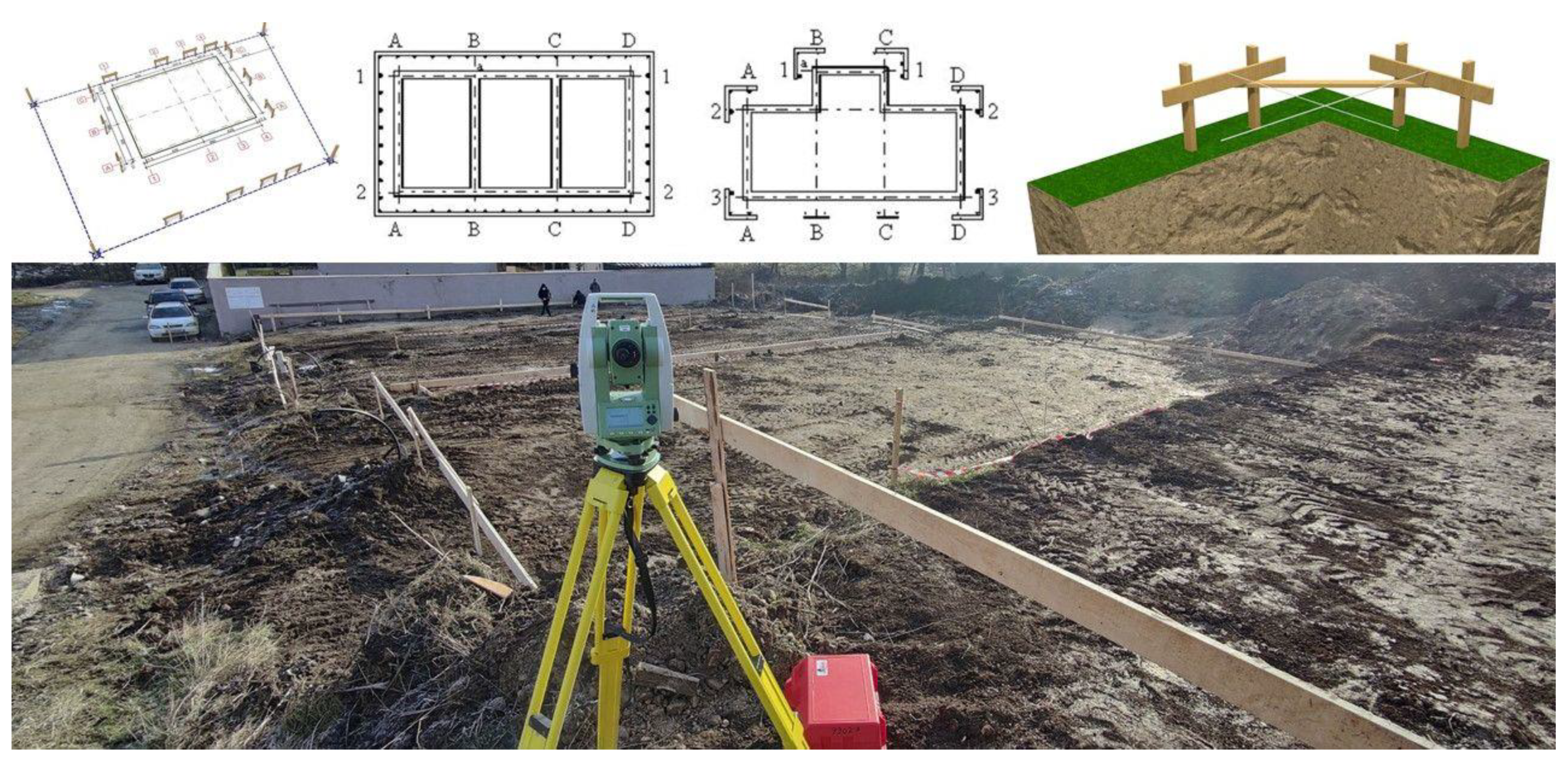
Batter boards are temporary wooden frameworks constructed and displayed around the in-site layout, used to suspend the layout strings for a foundation or a structural element from the ground floor. Their placement is crucial for building with the correct designed geometries. Batter boards consist of two vertical wood poles and a horizontal crosspiece screwed to the verticals (Figure 6). The height of the boards must be over the height of the finish floor elevation, and if possible, all horizontal crosspieces must have the same elevation. Batter boards are commonly set beyond the corners of a planned foundation, but they can also be continuous and cover the whole perimeter of the construction [1,4]. These batter boards are then used in order to layout or stake-out on them the axes of the construction, and by intersecting construction twine between two axes to indicate the precise location of a construction layout point.
Batter boards are very popular for small to medium scale construction sites. Survey engineers commonly use them in order to layout the construction axes, in order for the builder to further determine construction layout point without the help of instrumentation or survey expertise. This practice can be applied for smaller scale construction sites, because the intersection of construction twine in order to determine a layout point can be achieved for the foundation and the structural elements on the ground floor (columns, beams, load-bearing walls). This is because the elevation of the batter boards is usually at one meter above ground level, and it would be impossible to use them on an upper floor. Due to the high demand of construction survey and layout, the batter boards holding layout lines is a very popular solution [1,24].
There are several methods of axes layout on these wood structures, depending on the instrumentation used and the calculus capability of the user and apparatus. Thus, the present case study contains a novelty comparison between four methods of batter boards stake-out of the construction layout lines, in order to determine the most efficient way possible, as well as a comprehensive evaluation of the advantages and disadvantages of each method and the possible instrumentation used. The four methods consist of: the classical optical method using a theodolite; the survey of the batter boards with manual calculation of coordinate intersection between the wood plank and the construction axes; the survey of the batter boards with CAD implementation and extraction of coordinate intersection between the wood plank and the construction axes; reference line or layout line function of the total station. These four methods will be further presented and evaluated in the next chapter, with a dissemination of the results, discussion and concluding remarks.
3. Results
3.1. On-Site Design Points Layout
The on-site layout of the construction design points was carried out using the geodetic network established in the vicinity; respectively, control points St1 and St2. Each were used as a station point for the instrument, and the other one for orientation (bearing). The stake-out process can be made using the special COGO functions of the total station, or in the case of electrical theodolites, basic measurements of horizontal angles and distances are required. Total stations have built-in programs, usually named “Stake-out” or “Layout”, where you can select from the internal memory or manually enter the coordinate [1,4]. With the internal processing power, they instantly display the values of the horizontal angles at which the user has to rotate the instrument on the horizontal axis in order to be on the right direction, and the distance of the point on the established direction. Based on repeated measurements of angles and distances, and a good coordination between the survey engineer and the technical assistant wielding the reflector, the correct positioning of the design points are marked on the ground. In the case of electrical theodolites such as the Leica Builder series, the process is similar, with the exception of manually inserting the value of Hz = 0g (horizontal angle) in the direction of the second control point (used for orientation/bearing), with further manual positioning based on the calculated layout element present in the tables of the site layout plan.
In the next figure (Figure 7) it can be observed the general workflow of a construction layout point (e.g., A6) marked on-site, by following the steps previously mentioned. By careful rotation of the instrument on the horizontal axis, in order to not exceed ±(5–10)cc, and with layout distances of ±(2–3) mm, the achieved point standard deviation is relatively low, and more than enough for this type of project. The same steps are taken for all the important layout points, which the builder requests to be marked on site (usually the construction corners). For a better visualization of the site and the layout of the constructions inside the terrain, a georeferenced orthophoto was made using a UAV system (Figure 8). Because further earthworks for the foundation will be established, wooden stakes and topographic nails used to signal the layout points will be destroyed or removed from site. Thus, the batter boards are used in order for the survey engineer to display the construction layout lines that will help the builder redetermine the position of the design points and the construction geometry.
3.2. Results and Discussions Regarding the Batter Boards Layout Methods
3.2.1. Classical Method with Theodolite Instrument
The classical method of batter boards layout is based on the initial construction layout points on the ground. These points must be marked accordingly, with wood stakes and topographic nails, using stake-out methods and calculus as previously mentioned. After the construction layout points on the ground is complete, the survey engineer must leave the station point and move the theodolite on one of the points marked on the ground. After positioning and centering the instrument on the newly marked construction point, the user must target with the moveable telescope another of the construction layout points marked on the ground, but it is mandatory for the point to be on the same construction axes (geometry line). It is recommended to insert on the instrument menu the horizontal angle value at “0” (Hz = 0g), in order to notice any displacements or instrumental movements at the next stages. By lifting the theodolite telescope, the survey engineer must target the batter board in front of him, and guide the technical assistant with the reflector left and right on the respective wood plank until they determine a position collinear with their direction, and mark it accordingly. Then, the telescope is tilted 200g until it faces the opposite batter board; it must be checked if the angular reading remains approx. Hz = 0g; and the guidance process between the engineer and assistant is repeated in order to determine and mark the collinear point on the respective batter board. After that construction line is laid out, the team can rotate the instrument in order to create a right angle (at 100g or 300g, depending on the position) and target another construction layout point on the ground. The process is repeated, thus each next stationing on a construction layout point can assure the marking on the batter boards of two construction lines (axes). The presented figure (Figure 9) illustrates the established workflow, with stationing on point A6, targeting point A3 in order to lay out on the batter boards construction line A–A, and then rotating the instrument and targeting point I6 in order to lay out construction line 6–6.
The advantages of this method are that it can be performed with any optical instrument related to the theodolite, that includes any type of classical theodolite, electrical theodolite and total stations. Also, because it is an optical and mechanically applied method, the chances of error are low (considering that the ground layout points were correctly determined). Another advantage is the fact that the position of the construction layout points on the ground are verified when targeting points at a right angle (obtaining readings of 100g and 300g). The disadvantages of this method are numerous, because it has a low efficiency in terms of time. Also, due to the fact that it is necessary to station on points inside the construction site, which are usually on rough terrain or in the excavation for the foundations, there are dangers and inconveniences.
3.2.2. Survey of the Batter Boards and Manual Calculation
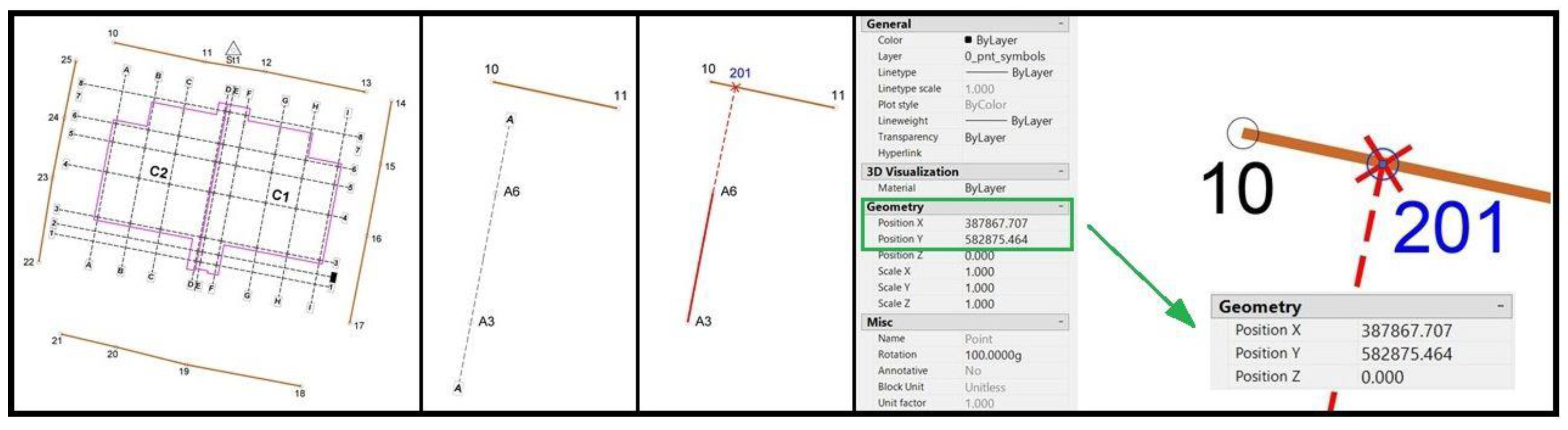
This method is based on the survey of the batter boards, in order to determine the coordinates of each side. This survey can be undertaken using a total station or an electronic theodolite with electronic distance measurement (EDM), and the survey can be carried out from one of the control points on site. The principle is to measure and obtain the coordinates of the wood plank at the middle of each side, in order to obtain a line or direction for each batter board (Figure 10). The calculus consists of determining the coordinate of the intersection between the construction line (axes) and the line representing the batter board. This can be obtained in a number of different ways, the easiest being to use an intersection of orientations (bearings). The orientations (bearings) will be calculated based on the designed coordinates (construction layout points) and the measured coordinates (each side of the wood plank). For example, in the case of construction line A–A and the measured batter board of points 10–11, the two bearings will be calculated as θA3–A6 and θ10–11 as previously mentioned in Section 2.4. We consider the new point 201 as the intersection between the two bearings, and in order to determine its coordinates, the bearing between point 10 and point 201 is needed, which is the same as the bearing of the batter board θ10–11 (point 201 is collinear on line 10–11). Also, the bearing between point A3 and point 201 is needed, which is the same as the bearing of the construction line A3–A6, calculated from the designed coordinates (Figure 11). Thus, the coordinates of point 201 can be obtained using the formulas:
The advantages of this method are that it can be performed with older models of total stations that do not have special functions (e.g., reference line/layout line) or with total stations where these functions are blocked and it is necessary to purchase additional software packages. It is an engineering alternative to the classical method, the actual layout on the batter board is easy and accessible to anyone, as it is a regular stake-out based on the polar coordinates method (horizontal angle and distance). The disadvantages of this method are again numerous, because it has a low efficiency in terms of time. Also, numerous errors can occur when measuring the wood planks and manually calculating these intersecting coordinates. Another disadvantage is the need for qualitative batter boards, because if the wood planks are bent and the survey is at each side, the resulting intersection of coordinates will be outside the wood section.
3.2.3. Survey of the Batter Boards and Computer-Aided Design (CAD) Implementation
This method is based on the same methodology and principle as the previous one, with the survey of the batter boards, in order to determine the coordinates of each side. The difference is that instead of a manual calculus of the intersecting coordinate, the survey data is exported inside CAD software, the same one used for establishing the site layout plan, and the batter boards are represented as polylines. Using the geometry functions, the construction line (axes) is extended until they intersect the new polyline (batter board), and the intersecting coordinate is extracted and inserted in the total station (Figure 12). The advantages of this method are that it can be performed with older models of total stations that do not have special functions (e.g., reference line/layout line) or with total stations where these functions are blocked and it is necessary to purchase additional software packages. Also, the actual layout on the batter board is easy and accessible to anyone, as it is a regular stake-out based on the polar coordinates method (horizontal angle and distance). The disadvantages of this method are numerous, because it has a low efficiency in terms of time. Also, numerous errors can occur when measuring the wood planks and the insert-export in CAD software, as well as the need to bring a laptop on-site. Another disadvantage is the need for qualitative batter boards, because if the wood planks are bent and the survey is at each side, the resulting intersection of coordinates will be outside the wood section.
3.2.4. Reference Line Function
This method is the most popular current choice for on-site layout in a construction survey. It is a special function or program inside the total station, and it is commonly called reference line or layout line (depending on the total station brand). This function creates a reference line between two of the characteristic points of the construction (measured or designed), and all future measurements are displayed with respect to this line. The displayed values are ΔL (line) and ΔO (offset), in regards to a newly observed (measured) point. These values represent the length/distance (ΔL) from the first reference point to the observed (measured) one, and the offset (ΔO) of the observed (measured) point from the reference line (displacement from collinearity). These values serve vital applications in the field that simplify most of the layout applications, and provide invaluable assistance to the survey engineer. By knowing these values, it is very accessible to lay out points at different lengths from each other or from a certain position, or lay out points collinear to a certain direction or at certain designed offsets. In the case of batter boards layout, the methodology is to create a reference line represented by a construction line (axes), and with repeated measurements to locate a collinear point on the batter board with the value of ΔO = 0.000 m. The values ΔL and ΔO are calculated from the designed and measured coordinates, and are based on trigonometry, as presented in Figure 13 and the following formulas:
The main advantage of this method is the efficiency in terms of execution time. It is the most popular layout method and can be used on any construction site and under any conditions. In terms of disadvantages, this method requires a newer model total station or to buy certain software packages. Also, it requires a better experience and teamwork between the survey engineer and assistant, as well as a better orientation in space than a normal polar coordinate stake-out.
4. Discussion
For the comparison between the layout lines methods, a trial-and-error method was implemented in the field in order to analyze the different geometries obtained. Because some of the methods can be considered old-fashioned with low efficiency, the precision and time were compared regarding the stake-out of four construction lines (axes), respectively eight markings on batter boards. Each method yielded feasible results, resulting in collinear markings on the batter boards, with very few and small deviations (as shown in the last picture of Figure 14). The second and third methods both produce the same coordinate for stake-out and the topographic nail representing this method is the middle one; the interior one was marked using the classical method and the exterior one was determined using reference line function. In terms of time efficiency, the methods were timed, achieving routinely predictable results: the batter boards survey with manual calculation of coordinates took longest, with roughly 2 h of work; the batter boards survey with CAD implementation as well as the classical theodolite method took approximately 1 h; the reference line method was the most efficient and easy to put into practice, with 15 min of implementation.
The desideratum was to mark reliable points on each batter board, in order for the builders to further position construction layout points without instrumentation and expertise. As shown in Figure 14, this is obtained using construction twine by stretching it between the points (nails) on the wood planks, and a mechanical projection with a plummet on the ground from the twine intersection. Although not as precise as a layout with a total station, this established method is viable for smaller to medium-scale projects, and can ensure a required point standard deviation of μP = ±(1–2) cm. These layout points are used by the builders for guidance regarding the excavation area, foundation and structural elements positioning, and assures the verticality of the erected building.
In future, building information modelling (BIM) will also have a significant impact on the work of surveyor engineers, as it is currently regarded as a major paradigm shift in the construction industry, especially for civil engineers and architects [31]. Traditional building design models depend to a large extent on two-dimensional technical drawings, and a BIM platform expands the three primary spatial dimensions (width, height and depth), integrating multiple advantages due to their economic benefits in design and construction phases [32,33]. Future perspectives include the establishment and integration of the site layout plan with the BIM design in order to achieve sustainable and productive practice regarding the construction industry.
5. Conclusions
The efficient layout planning of buildings in a construction site is a fundamental task for undertaking any project. In an attempt to enhance the general practice of layout planning of construction sites, the paper presents a retrospective for the surveyor engineer’s role in the construction industry, a design for a comprehensive site layout plan with on-site applicability and introduces a novel comparison between four methods of construction lines layout on batter boards. The presented general knowledge further cements the importance of geodetic specialists in the field, and the designed layout plan serves as guidelines for existing and future engineers, as well as researchers in the field. In this context, safety and freedom from hazard concerns are key factors for a productive construction survey and layout project. The comparison highlights the viable implementation of each of the four methods of batter board construction lines layout, especially in regard to the instrumentation used and the on-site conditions, with the undisputed recommendation of the reference line method due to its overall efficiency and accuracy. Given the current development and expanding implementations of BIM that also impact the work of surveyors, future investigations will be made in order to integrate the site layout plan inside the platform.
Funding
This research received no external funding.
Institutional Review Board Statement
Not applicable.
Informed Consent Statement
Not applicable.
Data Availability Statement
Not applicable.
Acknowledgments
The author would like to thank the Academic Editor and anonymous reviewers for their helpful and valuable comments and suggestions.
Conflicts of Interest
The author declares no conflict of interest.
References
- Bondrea, M.V.; Naş, S.; Fărcaş, R.; Dîrja, M.; Sestraş, P. Construction Survey and Precision Analysis Using RTK Technology and a Total Station at Axis Stake-Out on a Construction Site. In Proceedings of the 16th International Multidisciplinary Scientific GeoConference SGEM2016, Albena, Bulgaria, 28 June–7 July 2016; Volume 2, pp. 155–161. [Google Scholar]
- Baykal, O.; Tari, E.; Coşkun, M.Z.; Erden, T. Accuracy of point layout with polar coordinates. J. Surv. Eng. 2005, 131, 87–93. [Google Scholar] [CrossRef] [Green Version]
- Huang, C.; Wong, C.K. Optimisation of site layout planning for multiple construction stages with safety considerations and requirements. Automat. Constr. 2015, 53, 58–68. [Google Scholar] [CrossRef]
- Sestraş, P.; Bondrea, M.V.; Sălăgean, T.; Dîrja, M.; Cîmpeanu, S.M. Engineering Survey for Excavated Volume Calculation in a Construction Site Using a Total Station. In Proceedings of the 16th International Multidisciplinary Scientific GeoConference SGEM2016, Albena, Bulgaria, 28 June–7 July 2016; Volume 2, pp. 247–254. [Google Scholar]
- Cosarca, C. Considerations on the tolerances and precisions in engineering measurements. In Recent Advances in Geodesy and Geomatics Engineering-Proceedings of the 1st European Conference of Geodesy Geomatics Engineering; Technical University for Civil Engineering Bucharest: Bucharest, Romania, 2013; Volume 1, pp. 8–18. [Google Scholar]
- Herban, S.I.; Vîlceanu, C.B.; Grecea, C. Road-Structure Monitoring with Modern Geodetic Technologies. J. Surv. Eng. 2017, 4, 143. [Google Scholar] [CrossRef]
- Sestras, P.; Roșca, S.; Bilașco, Ș.; Naș, S.; Buru, S.M.; Kovacs, L.; Spalević, V.; Sestras, A.F. Feasibility Assessments Using Unmanned Aerial Vehicle Technology in Heritage Buildings: Rehabilitation-Restoration, Spatial Analysis and Tourism Potential Analysis. Sensors 2020, 20, 2054. [Google Scholar] [CrossRef] [Green Version]
- Drewes, H.; Kuglitsch, F.G.; Adám, J.; Rózsa, S. The geodesist’s handbook 2016. J. Geod. 2016, 90, 907–1205. [Google Scholar] [CrossRef]
- Hope, C.J.; Chuaqui, M. Precision surveying monitoring of shoring and structures. In Proceedings of the 7th FMGM 2007: Field Measurements in Geomechanics, Boston, MA, USA, 24–27 September 2007; Volume 1, pp. 1–12. [Google Scholar]
- Artese, S.; Perrelli, M. Monitoring a Landslide with High Accuracy by Total Station: A DTM-Based Model to Correct for the Atmospheric Effects. Geosciences 2018, 8, 46. [Google Scholar] [CrossRef] [Green Version]
- Afeni, T.B.; Cawood, F.T. Slope Monitoring using Total Station: What are the Challenges and How Should These be Mitigated? S. Afr. J. Geomat. 2013, 2, 41–53. [Google Scholar]
- Horemuž, M.; Andersson, J.V. Analysis of the precision in free station establishment by RTK GPS. Surv. Rev. 2011, 43, 679–686. [Google Scholar] [CrossRef]
- Sestras, P.; Bilașco, Ș.; Roșca, S.; Dudic, B.; Hysa, A.; Spalević, V. Geodetic and UAV Monitoring in the Sustainable Management of Shallow Landslides and Erosion of a Susceptible Urban Environment. Remote Sens. 2021, 13, 385. [Google Scholar] [CrossRef]
- Elbeltagi, E.; Hegazy, T.; Eldosouky, A. Dynamic layout of construction temporary facilities considering safety. J. Constr. Eng. 2004, 130, 534–541. [Google Scholar] [CrossRef]
- Ning, X.; Lam, K.C.; Lam, M.C.K. A decision-making system for construction site layout planning. Automat. Constr. 2011, 20, 459–473. [Google Scholar] [CrossRef]
- Cheng, M.Y.; O’Connor, J.T. ArcSite: Enhanced GIS for construction site layout. J. Constr. Eng. 1996, 122, 329–336. [Google Scholar] [CrossRef]
- Biljecki, F.; Heuvelink, G.B.M.; Ledoux, H.; Stoter, J. The effect of acquisition error and level of detail on the accuracy of spatial analyses. Cartogr. Geogr. Inf. Sci. 2018, 45, 156–176. [Google Scholar] [CrossRef] [Green Version]
- Berk, S.; Ferlan, M. Accurate area determination in the cadaster: Case study of Slovenia. Cartogr. Geogr. Inf. Sci. 2018, 45, 1–17. [Google Scholar] [CrossRef]
- Hanus, P.; Pęska-Siwik, A.; Szewczyk, R. Spatial analysis of the accuracy of the cadastral parcel boundaries. Comput. Electron. Agric. 2018, 144, 9–15. [Google Scholar] [CrossRef]
- Dolean, B.-E.; Bilașco, Ș.; Petrea, D.; Moldovan, C.; Vescan, I.; Roșca, S.; Fodorean, I. Evaluation of the Built-Up Area Dynamics in the First Ring of Cluj-Napoca Metropolitan Area, Romania by Semi-Automatic GIS Analysis of Landsat Satellite Images. Appl. Sci. 2020, 10, 7722. [Google Scholar] [CrossRef]
- Sestraş, P.; Sălăgean, T.; Bilașco, S.; Bondrea, M.V.; Naș, S.; Fountas, S.; Cîmpeanu, S.M. Prospect of a GIS based digitization and 3D model for a better management and land use in a specific micro-areal for crop trees. Environ. Eng. Manag. J. 2019, 18, 1269–1277. [Google Scholar] [CrossRef]
- Matei, I.; Pacurar, I.; Rosca, S.; Bilasco, S.; Sestras, P.; Rusu, T.; Jude, E.T.; Tăut, F.D. Land Use Favourability Assessment Based on Soil Characteristics and Anthropic Pollution. Case Study Somesul Mic Valley Corridor, Romania. Agronomy 2020, 10, 1245. [Google Scholar] [CrossRef]
- Kavanagh, B.F.; Slattery, D.K. Surveying: With Construction Applications; Pearson: Upper Saddle River, NJ, USA, 2010. [Google Scholar]
- Coşarcă, C. Măsurători Inginereşti: Aplicaţii în Domeniul Construcţiilor, 1st ed.; Matrix: Bucharest, Romania, 2011; pp. 22–93. [Google Scholar]
- Schofield, W. Engineering Surveying: Theory and Examination Problems for Students; Elsevier: London, UK, 2001. [Google Scholar]
- Anderson, J.M.; Mikhail, E.M. Surveying—Theory and Practice, 7th ed.; McGraw-Hill: New York, NY, USA, 2012. [Google Scholar]
- Uren, J.; Price, W.F. Surveying for Engineers; Macmillan International Higher Education: New York, NY, USA, 2010. [Google Scholar]
- Horemuž, M.; Jansson, P. Optimum establishment of total station. J. Surv. Eng. 2017, 2, 143. [Google Scholar] [CrossRef] [Green Version]
- Sun, H. Precision analysis of free-station positioning in total station. Adv. Mater. Res. 2013, 694, 1281–1285. [Google Scholar] [CrossRef]
- Jasiśńka, E. Determining the influence of position accuracy and measurements on the accuracy of the point determined by tacheometric measurement. In Proceedings of the 18th International Multidisciplinary Scientific GeoConference SGEM2018, Albena, Bulgaria, 2–8 July 2018; Volume 18, pp. 717–722. [Google Scholar]
- Kim, K.P.; Freda, R.; Nguyen, T.H.D. Building Information Modelling Feasibility Study for Building Surveying. Sustainability 2020, 12, 4791. [Google Scholar] [CrossRef]
- Bryde, D.J.; Broquetas, M.; Volm, J.M. The project benefits of Building Information Modelling (BIM). Int. J. Proj. Manag. 2013, 31, 971–980. [Google Scholar] [CrossRef] [Green Version]
- Durdyev, S.; Mbachu, J.; Thurnell, D.; Zhao, L.; Hosseini, M.R. BIM Adoption in the Cambodian Construction Industry: Key Drivers and Barriers. ISPRS Int. J. Geo-Inf. 2021, 10, 215. [Google Scholar] [CrossRef]
Figure 1.
A survey engineer’s typical workflow.

Figure 2.
Site location.

Figure 3.
Graphical abstract of the site layout plan process.

Figure 4.
Polar coordinates for layout point H7 and the topographic quadrants for the calculus.

Figure 5.
Site layout plan.

Figure 6.
Examples of batter boards (top); the present in-site conditions (bottom).

Figure 7.
General workflow of a construction layout point marked on-site.

Figure 8.
Layout site with an unmanned aerial vehicle (UAV) orthophoto layer.

Figure 9.
Typical workflow for theodolite method construction line layout.

Figure 10.
Batter boards survey.

Figure 11.
Construction lines and batter boards intersection.

Figure 12.
Intersection coordinate extraction.

Figure 13.
Reference line method applied on field (left) and general concept (right).

Figure 14.
Construction twine and batter boards markings used for layout points positioning; obtained markings of the 4 methods of batter board stake-out (right).
Figure 14.
Construction twine and batter boards markings used for layout points positioning; obtained markings of the 4 methods of batter board stake-out (right).

Publisher’s Note: MDPI stays neutral with regard to jurisdictional claims in published maps and institutional affiliations. |
© 2021 by the author. Licensee MDPI, Basel, Switzerland. This article is an open access article distributed under the terms and conditions of the Creative Commons Attribution (CC BY) license (https://creativecommons.org/licenses/by/4.0/).
Share and Cite
MDPI and ACS Style
Sestras, P. Methodological and On-Site Applied Construction Layout Plan with Batter Boards Stake-Out Methods Comparison: A Case Study of Romania. Appl. Sci. 2021, 11, 4331. https://doi.org/10.3390/app11104331
AMA Style
Sestras P. Methodological and On-Site Applied Construction Layout Plan with Batter Boards Stake-Out Methods Comparison: A Case Study of Romania. Applied Sciences. 2021; 11(10):4331. https://doi.org/10.3390/app11104331
Chicago/Turabian StyleSestras, Paul. 2021. "Methodological and On-Site Applied Construction Layout Plan with Batter Boards Stake-Out Methods Comparison: A Case Study of Romania" Applied Sciences 11, no. 10: 4331. https://doi.org/10.3390/app11104331
Note that from the first issue of 2016, this journal uses article numbers instead of page numbers. See further details here.