Article

Dynamic Response Analysis of a Thin Plate with Partially Constrained Layer Damping Optimization under Moving Loads for Various Boundary Conditions

1
Key Laboratory of High Efficiency and Clean Mechanical Manufacture, Ministry of Education, School of Mechanical Engineering, Shandong University, Ji’nan 250061, China
2
National Demonstration Center for Experimental Mechanical Engineering Education, Shandong University, Ji’nan 250061, China
3
Department of Bioresource Engineering, McGill University, Ste-Anne-de-Bellevue, Island of Montreal, QC H9X 3V9, Canada
*
Author to whom correspondence should be addressed.
Appl. Sci. 2021, 11(7), 3282; https://doi.org/10.3390/app11073282
Submission received: 9 March 2021 / Revised: 22 March 2021 / Accepted: 1 April 2021 / Published: 6 April 2021
(This article belongs to the Section Mechanical Engineering)

Abstract

:
In this paper, the vibration analysis of a partially constrained layer damping plate subjected to moving loads is investigated. In addition, the first four order damping loss factor of the system is optimized with the location of partially constrained layer damping as a design variable. The equations of motion of a partially constrained layer damping plate are derived through the Lagrange equation based on first order shear deformation theory (FSDT). Next, using an extended Rayleigh–Ritz solution together with the penalty method expresses the unknown displacement terms, and the differential quadrature method is proposed to obtain the dynamic response of the system in the time domain. A multi-population genetic algorithm (MPGA) is employed to deal with the optimization of the damping loss factor of a partially constrained layer damping plate. To ensure the accuracy of the method presented in this study, the numerical results are comprehensively verified by experiments and open literature. The optimization results show that the damping loss factor increases when the position of the patch is close to the constraint boundary, and the best strategy is to optimize the low order damping loss factor of the system under moving loads. It is believed that the research results are of interest to engineering science.

1. Introduction

Damping technology is one of the important methods to reduce the vibration and improve the performance of many engineering structures. The traditional passive damping method is to attach a viscoelastic damping material and a restraint layer to the controlled object. It has the advantages of a simple structure, easy implementation, wide control frequency, stability, reliability and low cost. It has been paid attention to by many researchers for many years. Partially constrained layer damping (PCLD) consists of a patch bonded to the structure to be damped. The patch is formed of a viscoelastic layer, constrained by a stiff layer covering part of the structure.
The mechanical and damping properties of sandwich structures have been studied for decades. Kerwin [1] proposed a sandwich structure consisting of a middle layer (damping layer) and an upper and lower layer (constrained layer) and investigated the damping factor of a sandwich plate. Mead et al. [2] derived the sixth order differential governing equation of a three-layer sandwich beam and studied the forced vibration of the beam by using the method of Di Taranto. Johnson et al. [3] applied the finite element method to predict the modal damping ratios in three-layer laminates. Lall et al. [4] analyzed the damping and vibration characteristics of a partially covered plate with a simple supported based on the Rayleigh–Ritz method. Cupial et al. [5] studied the free vibration of a rectangular sandwich plate with a viscoelastic layer by using the first order shear deformation theory (FSDT). Wang et al. [6] proposed the Galerkin method to analyze a sandwich plate. Banerjee et al. [7] presented an accurate dynamic stiffness model for a three-layered sandwich beam to study the free vibration characteristics of the beam. Ferreira et al. [8] investigated the dynamic problem of the sandwich laminated plates based on a layerwise finite element model, and the dynamic behavior of the model was validated by the public literature. Khalfi et al. [9] dealt with the harmonic and transient responses of a partially constrained layer damping plate. Hernandez et al. [10] studied the effects of the uncertainties of viscoelastic sandwich structures in passive and hybrid control strategies on their modal parameters. It can be seen from the above statement that many studies have focused on linear models. Some studies on nonlinear models have also been carried out. Kazeminia et al. [11] studied the realization of the variational iteration method in the Korteweg-de-Vries equation for actual and high-order nonlinear equations. Fazeli et al. [12] proposed the homotopy perturbation method to obtain explicit solutions to nonlinear fourth-order parabolic equations. Kazeminia et al. [13] proposed semi-analytical solutions of nonlinear differential equations with boundary value problems based on general Lagrangian multipliers. Zahedi et al. [14] presented a nonlinear dynamic response model of a screen machine which was described by nonlinear coupled differential equations and excited by a self-resonant control system. The nonlinear model has higher calculation accuracy, but it will increase the complexity and calculation time. Therefore, the nonlinear model is difficult to apply to engineering.
The optimization of the sandwich structures has also been studied in recent years. For such sandwich structures with constrained damping layers, many literatures focus on the optimization of damping loss factors or the dynamic response. The design variables optimized for these sandwich structures include material parameters, coverage area, thickness, location of the constrained damping layer and structure weight. Mantena et al. [15] investigated the optimal constrained viscoelastic tape to maximize damping in laminated beams. Marcelin et al. [16] studied the optimal damping of beams constrained by a damping layer based on an efficient finite element model. Ro [17] dealt with the optimal placement strategies of the active constrained layer damping to minimize the total weight of the damping treatment by using the modal strain energy method. Zheng et al. [18] carried out the optimization of the constrained layer damping treatment to minimize the vibration response of cylindrical shells, which are considered to transverse force excitation. Lepoittevin et al. [19] developed an optimization algorithm to optimize the loss factor of a segmented constrained layer damping beam. Zheng et al. [20] investigated the optimization of a constrained layer damping layout on the plates using a topology optimization tool. Kumar et al. [21] proposed a new 0–3 viscoelastic composite layer and the layer is arranged by an optimization algorithm. NAKRA [22] investigated the damping effectiveness of a partially covered plate, which include multi-parameter optimization techniques. Meanwhile, due to the rapid development of computers, many novel algorithms have been developed, such as genetic algorithm, neural network algorithm and so on. Some researchers applied these algorithms to optimize the sandwich structures and acquired good results. Marcelin et al. [23] dealt with the optimal damping of a sandwich beam covered by one or several portions and the optimization problem is solved by using a genetic algorithm. Zheng et al. [24] studied an optimization model to minimize the vibrational energy of a sandwich beam and employed a genetic algorithm-based penalty function to obtain the optimal solutions. Araújo et al. [25] considered the constrain optimization of the damping characteristics to maximize the damping loss factors based on the Feasible Arc Interior Point Algorithm. Hou et al. [26] applied a genetic algorithm with a large-scale mutation method to optimize the modal loss factor; the design variables include the thicknesses of the constrained layer and the viscoelastic layer and the shear modulus of the viscoelastic. Pathan et al. [27] proposed a real-coded constrained genetic algorithm to optimize the damping behavior of composite laminates. Sun et al. [28] employed a multiple population genetic algorithm to find the best coating location of a cantilever titanium plate, which aims to obtain the maximum modal loss factor. Gao et al. [29] applied a multi-objective genetic algorithm to solve the multi-objective function of the hard-coating blisk. From the above discussion, it can be found that many researchers have done some work on the optimization of the damping loss factor of the sandwich structure based on some optimization algorithms. However, the optimal damping loss factor with the constrained damping layer position as the design variable is rare. This paper deals with the optimal location of the constrained damping layer of a sandwich plate to maximize the damping loss factor by using a multi-population genetic algorithm (MPGA).
In addition, the dynamic behavior of structures under moving loads is also the focus of the engineering field, especially bridges, roads and mechanical engineering. Fryba [30] proposed several analytical solutions on the moving loads problem. Gbadeyan et al. [31] considered a theory that has arbitrary end support and is under an arbitrary number of masses to obtain the dynamic response of beams and rectangular plates. Kim et al. [32] investigated the dynamic response of a plate on a viscous Winkler foundation under moving loads of varying amplitudes and developed a formulation by using a triple Fourier transform and a double Fourier transform. Wu [33] concerned the dynamic behavior of a rectangular plate under curvilinear moving loads based on the finite element method (FEM), which transforms all the external loads into equivalent forces on corresponding nodes. Lee et al. [34] studied the dynamic analysis of composite plates under multi-moving loads based on a third order shear deformation theory (TSDT) and applied the 7-DOF finite element model to analyze the vibration problem. Ghafoori et al. [35] finished the dynamic characteristic of angle-ply laminated composite plates subjected to moving loads based on a first-order theory and employed the Newmark method to solve the equations of motion by integrating in the time domain. Amiri et al. [36] dealt with the vibration analysis of a Mindlin plate under a moving mass based on the first order deformation theory and used the direct separation of variables and the eigenfunction expansion method to transform the three basic variables into a series (the eigenfunction of plate free vibration). Esen et al. [37] proposed a new element to analyze the transverse vibration of the plates under moving loads. Malekzadeh et al. [38] carried out the dynamic response of a functionally graded plate in a thermal environment under a moving load by using FEM with Newmark’s time integration scheme. Song et al. [39] applied the Rayleigh–Ritz solution to investigate the dynamic behavior of the sandwich plate under moving loads.
From the above statement, the dynamic responses of plates under moving loads attract many researchers. Currently, there is little research on the dynamic response of a partially constrained layer damping plate under moving loads. Furthermore, the relationship between the optimization of damping and the dynamic response of plates under moving loads is still unknown. This study investigated the dynamic response analysis of a thin plate with partially constrained layer damping optimization under the moving loads for various boundary conditions.
In this paper, a numerical dynamic model of a partially covered plate under moving loads was established based on the Lagrange equation. The trigonometric function and power function were adopted for achieving a fast and accurate convergence. The differential quadrature method is used to solve the time domain of the system with high precision. The MPGA is employed to deal with the optimization of damping loss factors with the location of partially constrained layer damping as the design variable. The experimental verification of the optimization results is completed. Then, the optimization problem is analyzed by discussing the coverage of different sizes and different boundaries. Finally, the relationship between the optimization of the damping loss factor and the dynamic response is performed.

2. Theoretical Formulation

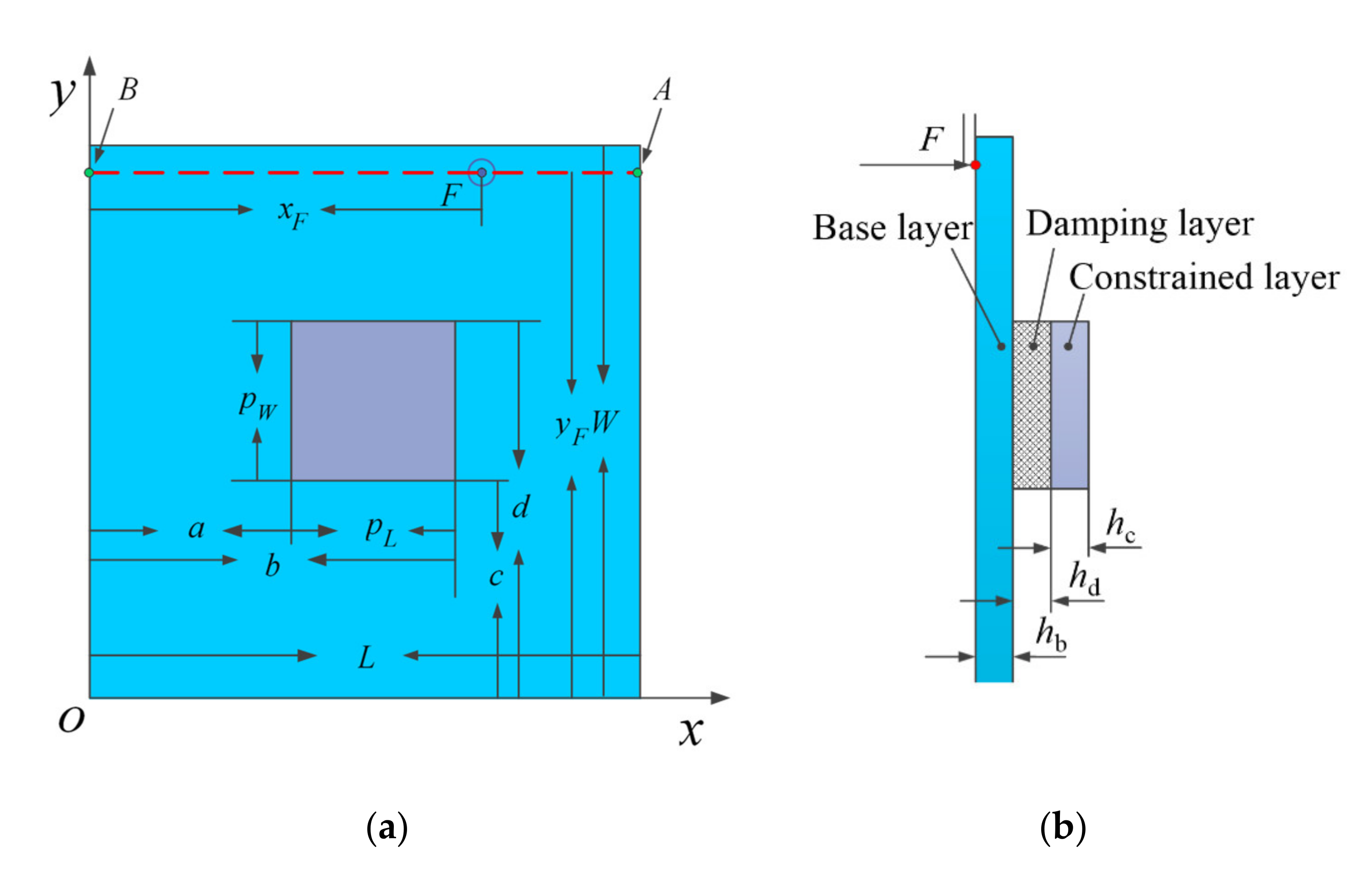
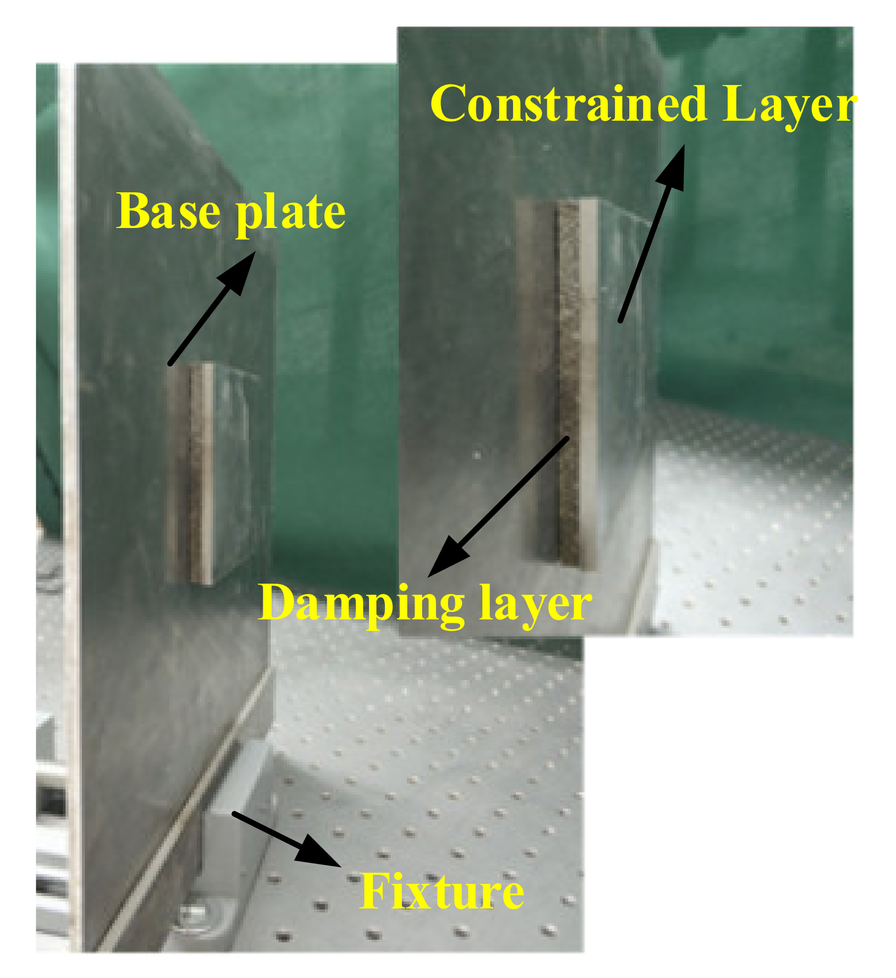
2.1. Model of Partially Covered Plate under Moving Loads

As shown in Figure 1, a partially covered cantilever plate consists of three layers, which are the b-base layer, d-damping layer and c-constrained layer. In this paper, the external force is assumed as a moving concentrated force, which moves from point A to point B in a constant velocity vF. In Figure 1a, the small green point in the black circle means the force is perpendicular to the paper and toward the outside. The direction of the force is also clearly depicted from the left view in Figure 1b. The path of the external force, denoted by a red dotted line, is parallel to the o-x axis. The boundary constraint is imposed by some spring supports with very high stiffness. In this study, the following widely adopted assumptions [1] are raised to derive the energy expression of the sandwich plate:
(a) For the base plate and constrained plate, the effect of rotatory inertia and normal stresses along the thickness are taken to be negligibly small.
(b) The normal to the undeformed middle surface remains straight, and the normal to the deformed middle surface is unstretched in length.
(c) The transverse displacement at a section is considered not to vary along the thickness and the longitudinal displacements are assumed to vary linearly along the thickness.
(d) No slip occurs at the interfaces between different layers.
(e) The damping layer is only subjected to shear stress and the modulus of the viscoelastic material is considered to be complex; Gd = Gd × (1 + ), where β is the loss factor of the viscoelastic material and j is the imaginary unit.

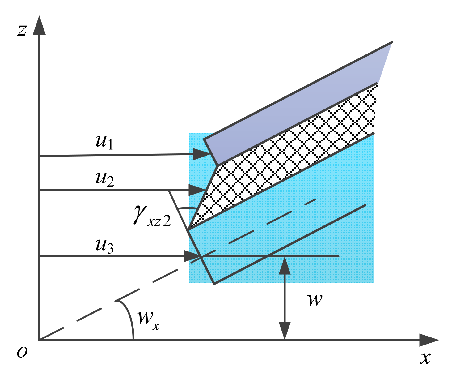
2.2. Governing Equation

In order to accurately describe the motion of the sandwich plate, nine displacement components, namely w, uc, ud, ub, vc, vd, vb, γxz,d, and γyz,d are required. Subscripts c, d, and b represent the constraining layer, damping layer and base plate, respectively. w, u, and v represent the displacement along the o-z axis, o-x axis, and o-y axis, respectively. γ is the shear strain in the damping layer and its subscripts represent the shear plane, where the first subscript denotes the direction of the strain. Figure 2 shows the longitudinal displacement of the sandwich plate in the x-z plane. Based on assumptions c and d, the following relationship can be obtained
u c + h c 2 w , x = u d + h d 2 γ x z , d - w , x u b - h b 2 w , x = u d - h d 2 γ x z , d - w , x
where w,x represents the partial derivative of w with respect to x ( w , x = w x ); hc, hd, and hb are thicknesses of the constrained layer, damping layer and base plate, respectively. From Equation (1), ud, vd, γxz,d, and γyz,d can also be expressed as
u d = u c + u b 2 + h c + h b 4 w , x , v d = v c + v b 2 + h c + h b 4 w , y γ x z , d = u c u b h d + h h d w , x , γ y z , d = v c v b h d + h h d w , y
where h = hd+(hc+ hb)/2, w,y represents the partial derivative of w with respect to y ( w , y = w y ).
Based on assumptions (a) and (b), constrained layer and base plate are under plane stress. The stain-displacement relationship is:
ε x , c = u c , x z w , x x , ε y , c = v c , y z w , y y ε x , b = u b , x z w , x x , ε y , b = v b , y z w , y y γ xy , c = u c , y + v c , x 2 z w , x y , γ xy , b = u b , y + v b , x 2 z w , x y
where w,xx, w,yy, w,xy represent the partial derivatives of w,x (w,y) with respect to x (y) ( w , x x = 2 w x 2 , w , y y = 2 w y 2 , w , x y = 2 w x y ). The corresponding constitutive relation is:
σ x , c = E c 1 μ c 2 u c , x + μ c v c , y z w , x x + μ c w , y y σ y , c = E c 1 μ c 2 u c , y + μ c v c , x z w , y y + μ c w , x x σ x , b = E b 1 μ b 2 u b , x + μ b v b , y z w , x x + μ b w , y y σ y , b = E b 1 μ b 2 u b , y + μ b v b , x z w , y y + μ b w , x x τ xy , c = E c 2 1 + μ c u c , y + v c , x 2 z w , x y τ xy , b = E b 2 1 + μ b u b , y + v b , x 2 z w , x y τ xz , d = E d 2 1 + μ d γ xz , d , τ yz , d = E d 2 1 + μ d γ yz , d
where μ and E represent the Poisson ratio and elasticity modulus, respectively. For the constrained layer, its strain energy Uc is:
U c = 1 2 a b c d h d / 2 h d / 2 σ x , c ε x , c + σ y , c ε y , c + τ xy , c γ xy , c d x d y d z
For the damping layer, based on assumption e, its strain energy Ud is:
U d = 1 2 a b c d h d / 2 h d / 2 τ xz , d γ xz , d + τ yz , d γ yz , d d x d y d z
Substituting Equations (3) and (4) into Equations (5) and (6), Uc and Ud can be expanded as:
U c = 1 2 a b c d E c h c 1 μ c 2 u c , x 2 + v c , y 2 + 2 μ c u c , x v c , y + 1 μ c 2 u c , y + v c , x 2 + E c h c 3 12 1 μ c 2 w , x x 2 + w , y y 2 + 2 μ c w , x x w , y y + 2 1 μ c w , x y 2 d x d y
U d = G d 2 h d 2 a b c d u c u b + w , x h 2 + v c v b + w , y h 2 d x d y
The strain energy of the base plate, Ub, can be expressed as:
U b = 1 2 0 L 0 W E b h b 1 μ b 2 u b , x 2 + v b , y 2 + 2 μ b u b , x v b , y + 1 μ b 2 u b , y + v b , x 2 + E b h b 3 12 1 μ b 2 w , x x 2 + w , y y 2 + 2 μ b w , x x w , y y + 2 1 μ b w , x y 2 d x d y
The total strain energy of the sandwich plate is:
U = U c + U d + U b
For the kinetic energy of the sandwich plate, the transverse inertia is only considered and the total kinetic energy is:
T = 1 2 a b c d ρ c h c + ρ d h d w ˙ 2 d x d y + 0 L 0 W ρ b h b w ˙ 2 d x d y
where ρi (i = c, d and b) is the density for different layers. The potential energy of the moving load can be expressed as:
W = W F + W M
For moving mass, the force due to weight and inertia can be expressed as:
F M = M g + M w ¨ ( x M , y M , t ) δ ( x x M ) δ ( y y M )
where xF = vF × t, yF is a constant value and δ(.) denotes the Dirac delta-function. The potential energy due to the weight and inertia of the moving load, can be written as:
W M = 0 L 0 W M g + M w ¨ ( x M , y M , t ) δ ( x x M ) δ y y M w ¨ ( x , y , t ) d x d y = M g + w ¨ ( x M , y M , t ) w ( x M , y M , t )
As shown in Figure 1a, the external force can be expressed as:
F q ( x , y , t ) = f q ( t ) δ ( x x F ) δ ( y y F ) , q = x , y , z
where xF = vF × t, yF is a constant value and δ(.) denotes the Dirac delta-function. The work done by the external force, Fq, is given by:
W F = 0 L 0 W w ( x , y , t ) F z ( x , y , t ) + u b ( x , y , t ) F y ( x , y , t ) + v b ( x , y , t ) F x ( x , y , t ) d x d y = f z ( t ) w ( x F , y F , t ) + f y ( t ) u b ( x F , y F , t ) + f x ( t ) v b ( x F , y F , t )

2.3. Rayleigh–Ritz Solution and Response

From Equations (7)–(9), (11) and (16), it can be seen that only five unknown parameters are needed to obtain the total energy of the cutting system, namely, w, uc, ub, vc, vb. In this paper, the Rayleigh–Ritz method (RRM) is used to approximately express the displacement components. The N*N-terms Rayleigh–Ritz solutions for the problem are of the following form:
w = i = 1 N j = 1 N w i j ( t ) φ i ( x ) ψ j ( y ) , u b = i = 1 N j = 1 N p i j ( t ) φ i ( x ) ψ j ( y ) , v b = i = 1 N j = 1 N q i j ( t ) φ i ( x ) ψ j ( y ) u c = i = 1 N j = 1 N r i j ( t ) φ i ( x ) ψ j ( y ) , v c = i = 1 N j = 1 N s i j ( t ) φ i ( x ) ψ j ( y )
where wij, pij, qij, rij, and sij are Ritz coefficients (or generalized modal coordinates) and φi(x) and ψj(y) are admissible functions. It should be noted that, unlike conventional Rayleigh–Ritz solutions, the admissible functions adopted here just satisfy a totally unconstrained condition and Courant’s penalty method is used to handle constraints. As shown in Figure 1, the clamped constraint in y = 0 is realized by some springs with high stiffness, where translational springs are used to limit the transverse displacement, w, in y = 0, and torsional springs are applied in y = 0 to limit the rotation, wy. To improve the numerical stability and convergent rate following admissible functions, permitting non-zero displacement and translation at both ends for a free-free beam are adopted.
x direction : φ i ( x ) = x L i 1 , i = 1 , 2 , 3 cos ( i 3 ) π x L , i = 4 , 5 , , N y direction : ψ j ( y ) = y W j 1 , j = 1 , 2 , 3 cos ( j 3 ) π y W , j = 4 , 5 , , N
The advantage of this improvement in RRM is that it is not needed to find satisfied admissible functions for different boundary conditions while the convergence of the solution is improved.
For the cantilever sandwich plate described in Figure 1a, the additional strain energy of the translational and rotational springs is:
V spring = i = 1 4 V ( i )
Here:
V ( 1 ) = 1 2 k z , t ( 1 ) 0 W w 2 x = 0 d y + 1 2 k z , r ( 1 ) 0 W w , x 2 x = 0 d y + 1 2 k x , t ( 1 ) 0 W u 2 x = 0 d y + 1 2 k x , r ( 1 ) 0 W u , x 2 x = 0 d y + 1 2 k y , t ( 1 ) 0 W v 2 x = 0 d y + 1 2 k y , r ( 1 ) 0 W v , x 2 x = 0 d y V ( 2 ) = 1 2 k z , t ( 2 ) 0 L w 2 y = 0 d x + 1 2 k z , r ( 2 ) 0 L w , y 2 y = 0 d x + 1 2 k x , t ( 2 ) 0 L u 2 y = 0 d x + 1 2 k x , r ( 2 ) 0 L u , y 2 y = 0 d x + 1 2 k y , t ( 2 ) 0 L v 2 y = 0 d x + 1 2 k y , r ( 2 ) 0 L v , y 2 y = 0 d x V ( 3 ) = 1 2 k z , t ( 3 ) 0 W w 2 x = L d y + 1 2 k z , r ( 3 ) 0 W w , x 2 x = L d y + 1 2 k x , t ( 3 ) 0 W u 2 x = L d y + 1 2 k x , r ( 3 ) 0 W u , x 2 x = L d y + 1 2 k y , t ( 3 ) 0 W v 2 x = L d y + 1 2 k y , r ( 3 ) 0 W v , x 2 x = L d y V ( 4 ) = 1 2 k z , t ( 4 ) 0 L w 2 y = W d x + 1 2 k z , r ( 4 ) 0 L w , y 2 y = W d x + 1 2 k x , t ( 4 ) 0 L u 2 y = W d x + 1 2 k x , r ( 4 ) 0 L u , y 2 y = W d x + 1 2 k y , t ( 4 ) 0 L v 2 y = W d x + 1 2 k y , r ( 4 ) 0 L v , y 2 y = W d x
where kt and kr are stiffness coefficients of the translational and rotational springs, respectively, and both of them take high value. Therefore, for this system, the Lagrangian is L = TU - V and the work done by nonconservative forces is WF. Using the Lagrange equation, the governing equation of motion of the system can be given by:
M 11 + M 11 * 0 0 0 0 0 0 0 0 0 0 0 0 0 sym . 0 w ¨ p ¨ q ¨ r ¨ s ¨ + C 11 * 0 0 0 0 0 0 0 0 0 0 0 0 0 sym . 0 w ˙ p ˙ q ˙ r ˙ s ˙
+ K 11 + K 11 * + K 11 K 12 K 13 K 14 K 15 K 22 + K 22 K 23 K 24 0 K 33 + K 33 0 K 35 K 44 K 45 sym . K 55 w p q r s = F z ( t ) F x ( t ) F y ( t ) 0 0
where 0 is the N × N zero matrix, over-double-dot denotes double differentiation with respect to time, w = [w11 w12w1N w21wNN]T, p = [p11 p12p1N p21pNN]T, q = [q11 q12q1N q21qNN]T, r = [r11 r12r1N r21rNN]T, s = [s11 s12s1N s21sNN]T and
M 11 + M 11 * w ¨ + C 11 * w ˙ + K 11 + K 11 * + K 11 + K inv w = F z ( t )
Here:
K inv = K 12 K 13 K 14 K 15 K 22 + K 22 K 23 K 24 0 K 33 + K 33 0 K 35 K 44 K 45 sym . K 55 K 12 K 13 K 14 K 15 T
Equation (22) can also be written in the compact form:
M ( t ) y ¨ ( t ) + C ( t ) y ˙ ( t ) + K ( t ) y ( t ) = F ( t )
where y(t) = w(t) and F(t) = Fz(t) are displacement vector and force, and mass M(t), damping C(t) and stiffness K(t) matrixes are of the order (N2 × N2). The detailed expansion formula is shown in Appendix A. Mathematically, Equation (24) is a system of coupled ordinary differential equations of second-order in time, which can be solved using various explicit or implicit time step methods. In this study, Equation (24) is solved by using the differential quadrature time integration scheme [39]. In addition, the natural frequency ω and the damping loss factor η can be obtained by solving the eigenvalue Equation (24) when the force is zero.

3. Optimization Problem

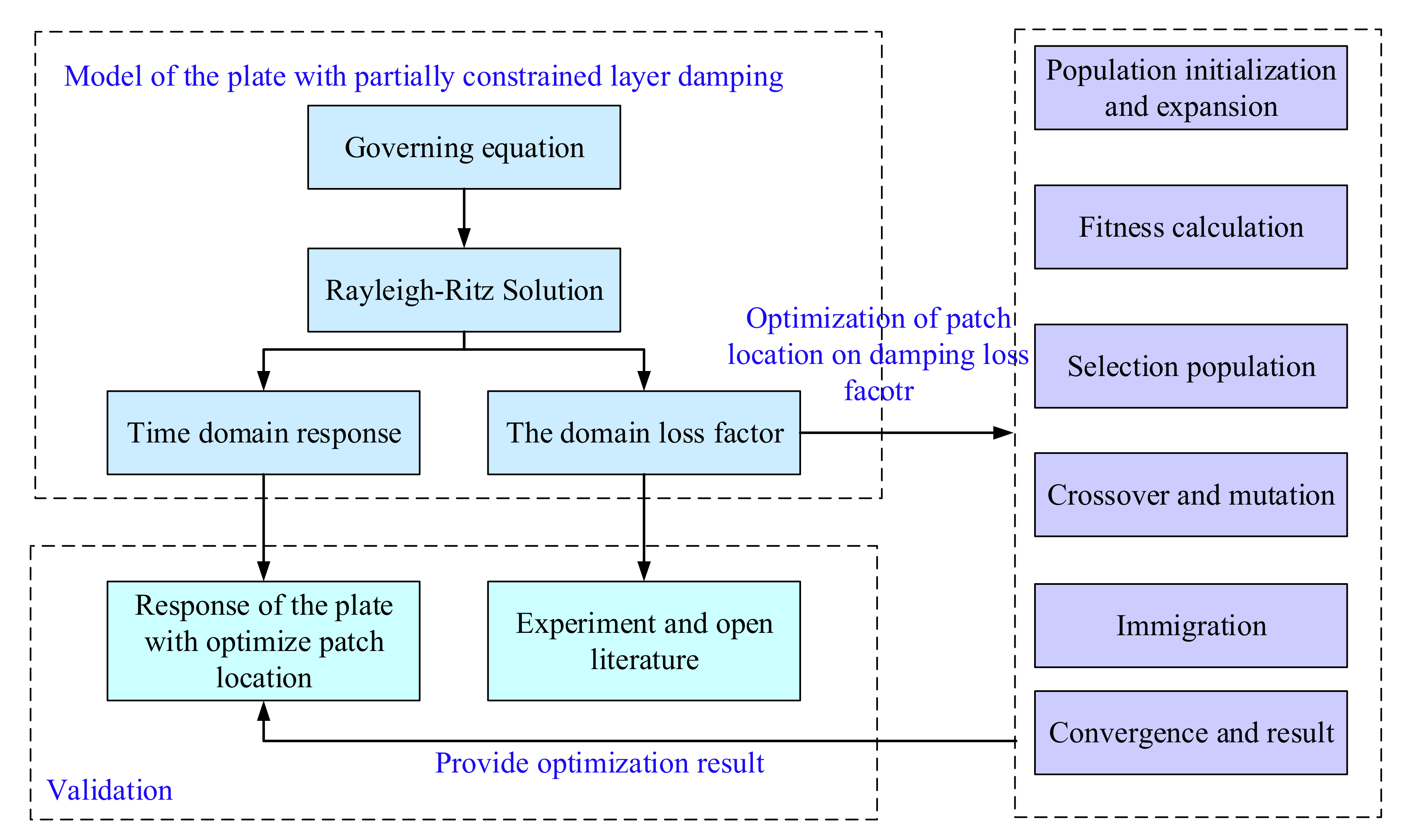
3.1. Optimization Process

In this section, the main research structure is shown in Figure 3. Firstly, the model of the partially constrained damping plate under a moving load is established, and the damping loss factor of the plate is optimized by multi-population genetic algorithms. Secondly, the verification content is divided into two parts. The first part is to verify the accuracy of the model through experiments and open literature. The second part is to verify the accuracy of the optimization through the dynamic response of the partially constrained damping plate. At this point, the accuracy of the model and algorithm are comprehensively verified. In addition, there are some parts not shown in the structure, which is a discussion of the influence of various parameters on the results.

3.2. Objective Function

Partially constrained layer damping composite plates are widely used to suppress vibration, especially in civil and mechanical engineering. The damping loss factor is one of the most important parameters of composite plates and varies with the position of the constrained damping layer. The optimization goal of this study is to obtain the optimal location for the patches (constrained damping layer) of different sizes to ensure the maximum damping loss factor of the composite plate with partial constraining damping. This optimization problem is described by the previously derived model. It can be seen that the position coordinates (a, b, c, d) of the patch are defined as the design variables shown in Figure 1. The length and width of the patch are PL and PW, respectively. In this study, the size of the patch is a constant. Thus, the optimization objective function can be formulated as:
max : f x , y = η i , i = 1 ,   2 ,   3 s . t .   :   0 x L P L 0 y W P W
where η i represents the loss factors and subscript i is the order of the loss factors. Optimization variables x and y correspond to a and c, respectively.

3.3. Solution Methodology

In this study, the multi-population genetic algorithm (MPGA) is adopted to solve the proposed optimization problem. MPGA is an excellent probability search algorithm for global optimization. Based on the standard genetic algorithm (SGA), MPGA decomposes the SGA into several subpopulations by the idea of multi-population parallel evolution and increases the number of gene patterns by exchanging information among subpopulations (usually the optimal individuals) to avoid immature convergence. Figure 4 shows the algorithm structure of MPGA, where immigration represents the best individual replacing the worst individual in the target population and selection represents the best individuals in different groups being selected and stored in elite populations to ensure that the optimal individuals generated by various groups are not destroyed or lost. Therefore, MPGA solves the shortcomings of SGA.
The calculation process of MPGA can be described as:
  • Population initialization and expansion: N populations are initialized, each of which has a binary chromosome, and the binary chromosome is transformed by the range of values of the x, y variables as shown in Equation (25).
  • Fitness calculation: Fitness is applied to distinguish between individuals in a population. In this study, the objective function value is the maximum damping loss factor, so the objective function is employed as the fitness function. The larger the objective function, the greater the fitness and the better the individual.
  • Selection: From the old population, good individuals are selected with a certain probability to form a new population to reproduce the next generation of individuals.
  • Crossover and mutation: The crossover is the random selection of two individuals from the population to, through the exchange and combination of two chromosomes, produce new, excellent individuals. The mutation is to randomly select an individual from the population and select a point in the individual to mutate to produce a better individual.
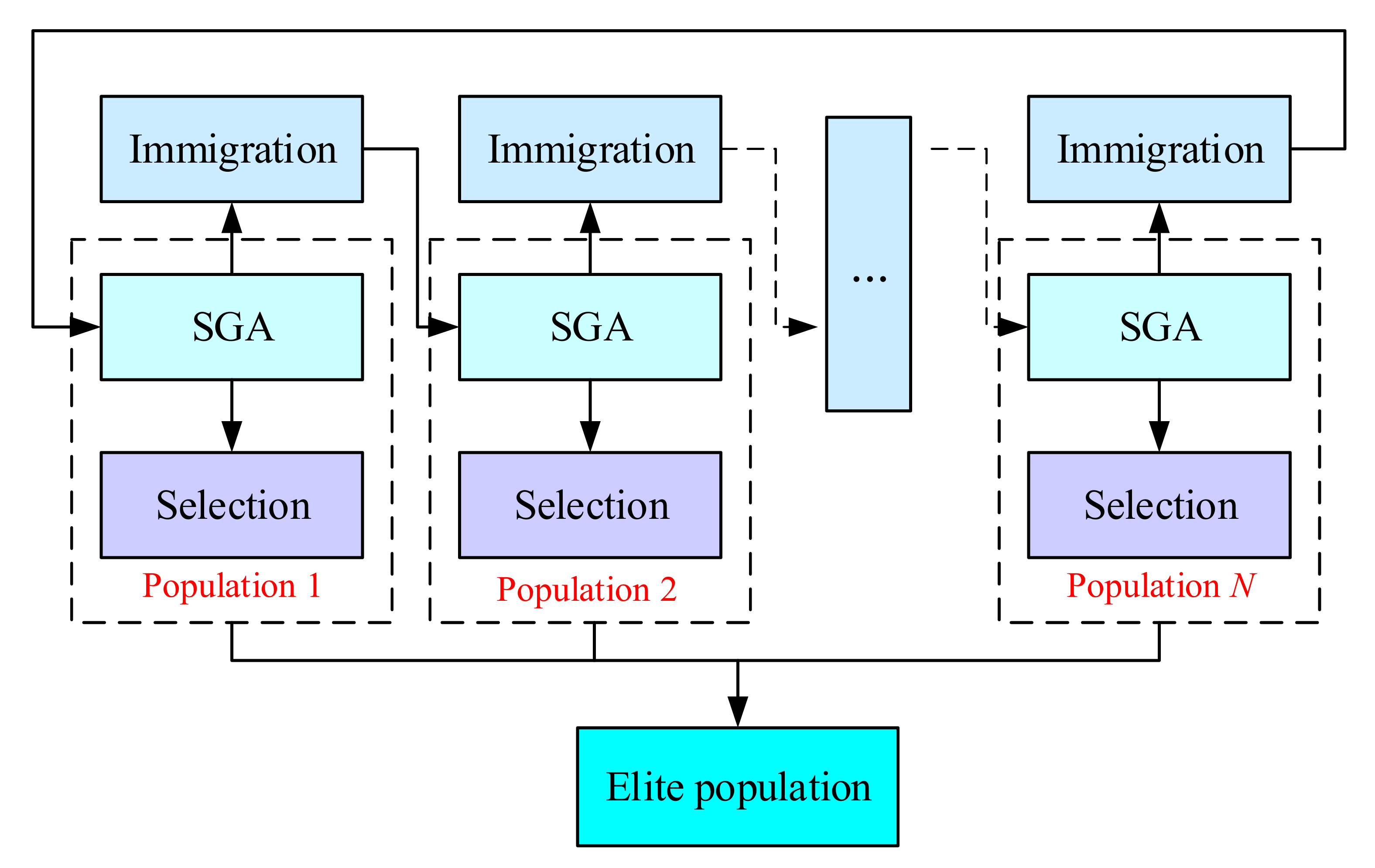
  • Immigration: The immigration is to replace the worst individual in the target population with the best individual in the original population, so as to achieve the goal of multi-population co-evolution.
  • Convergence: MPGA determines the algorithm to terminate based on the elite population. Then, the optimized variables (x, y) and damping loss factor η are obtained.

4. Result Analysis

4.1. Validation

In this section, the previously derived model and optimization algorithm will be verified by comparing the data of the experiment and the open literature.
To verify the accuracy of the present method, an SSSS partially covered composite plate is taken into account. The geometry and material properties of the simply supported square composite plate are as follows: L = W = 0.4 m, hb = 0.005 m, hd = 0.0025 m, hc = 0.0005 m, ρb = ρc = 7800 kg/m3, ρd = 2000 kg/m3, β = 0.38, Ec = Eb = 207.0 GPa, Gd = 4.0 MPa, and μc = μb = 0.334. The partially covered plate with the patch location is shown in Figure 5. The natural frequency and loss factor of the first mode for the partially covered composite plate, as shown in Table 1, are compared with the numerical results of the open literature. It can be seen that the results obtained in this paper are in good agreement with those in the literature [22]. This validation ensures the accuracy in analyzing the partially covered sandwich plate. The position of the patch is on the center of the sandwich plate.
As seen in Figure 5, a cantilever composite plate with a partially constrained damping layer is used for modal testing. The material of the base plate and constrained layer are both selected aluminum alloy 5052. The material of the damping layer is selected aluminum foam. The material and geometric parameters of the composite plate are shown in Table 2. The equipment employed for modal testing includes an impact hammer (PCB MIH03 with sensitivity of 10 mV/l bf) and an accelerometer (DYTRAN 3032A with sensitivity 10.00 mV/g). The signals are recorded with a data acquisition system supported by the B&K corporation. The position coordinates, a, b, c, d, of the patch are 0.085, 0.085, 0.185, and 0.185, respectively. Table 2 shows the detailed parameters of the composite plate (material and geometric) [40].
After the collection and analysis of experimental data, the experimental and theoretical calculation results are listed in Table 3 and Table 4. It can be clearly seen that the difference between the experiment, calculation and error results are also counted in the table. All the errors are within the acceptable range, which fully shows the accuracy of the theoretical model in this study.

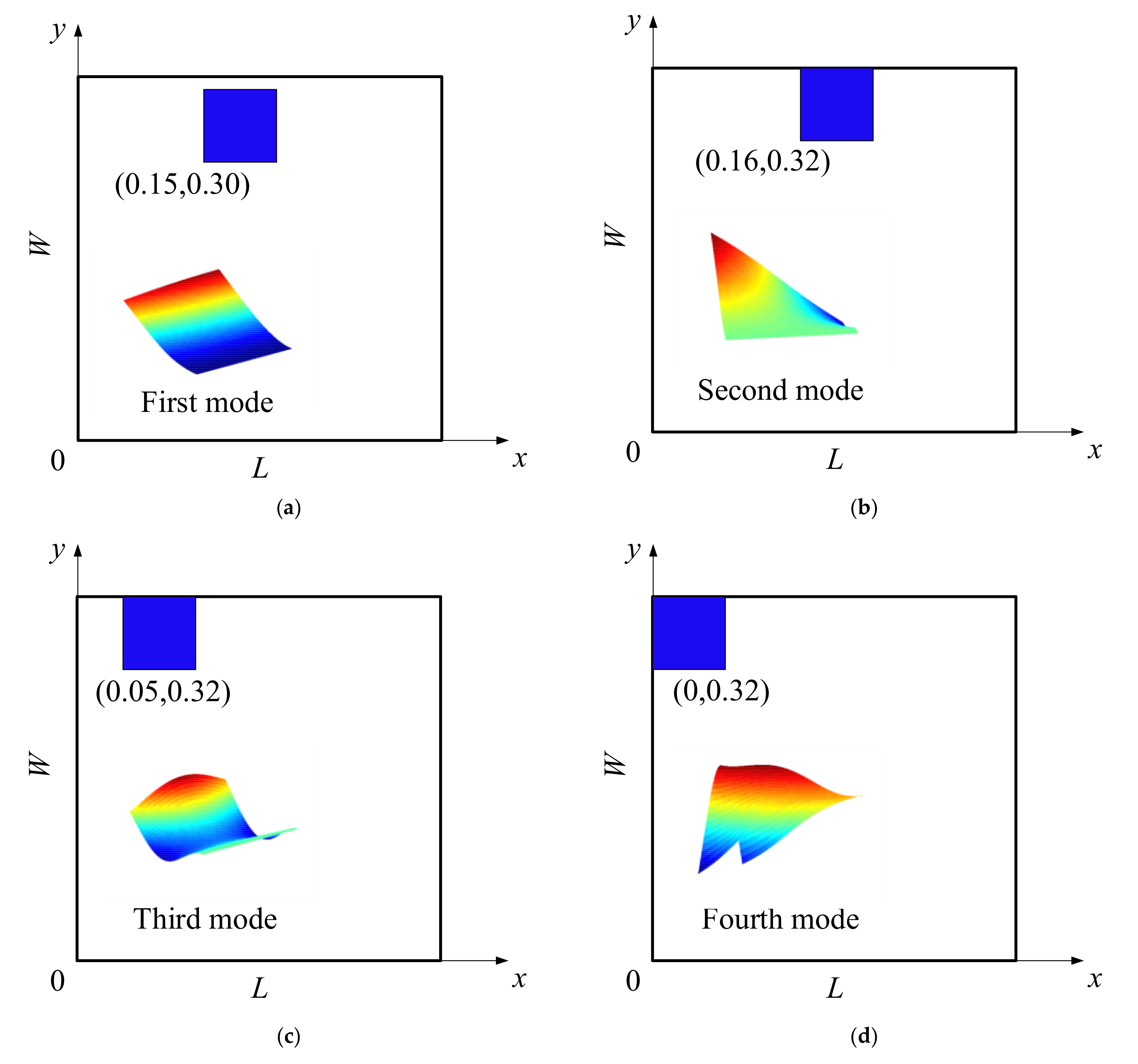
4.2. Optimization of Patch Location on Damping Loss Factor

In this section, a numerical analysis is carried out to study the optimal patch location for a sandwich plate with partial constraining damping in four different boundary conditions (CFFF, CFCF, SFSF CGSF) and the first four order damping loss factors are taken into account. There are four classical boundary conditions (F-free, S-simply supported, C-clamped and G-guided) in this paper. The basic parameters of MPGA are shown in Table 5. The geometry and material properties are as follows: L = W = 0.4 m, LP = WP = 0.08 m, hc = hb = hd = 0.005 m, ρb = ρc = 7800 kg/m3, ρd = 2000 kg/m3, Ec = Eb = 207 GPa, Gd = 4 MPa, and β = 0.38.
Then the simulation results can be obtained according to the above conditions and all calculations are done by using MATLAB software. For CFFF, it can be clearly seen that the optimal location and vibration modes of the first four order are shown in Figure 6. The blue square patch represents the constrained damping layer, and the numbers in parentheses represent the coordinates of the lower left corner of the patch. The mode shapes in Figure 6a–d correspond to the location of the patch. In fact, the location of the patch has little effect on the mode shapes by comparison. Figure 6 indicates that the optimal locations of each order are far from the fixed constraints. In practice, far away from the fixed constraints, there is a greater dynamic response under external forces. Therefore, it is a reasonable optimization result. The first four loss factors of a sandwich plate with partially constrained layer damping after optimizing the location of the patch are shown in Table 6. In Table 6, bold numbers indicate the results of the loss factor optimization for the corresponding order. With the increase in order, the loss factor decreases gradually and the loss factor of the optimized target order is greater than others.
Further, the same optimization is carried out for the other three boundary conditions (CFCF, SFSF CGSF) and all optimization results are shown in Table 7. For the sake of simplicity, only the coordinates of the patch and the target order loss factor are displayed after optimization. Then, the influence of the boundary conditions on the optimization of the damping loss factor can be analyzed, based on the simulation results. CFCF and SFSF have almost the same patch optimization location, but the damping loss factor of the former is always smaller than that of the latter. For CGSF, the optimal location of the patches is always on the free boundary, which is similar to CFFF. Therefore, it can be concluded that there will be a greater loss factor away from the constraint.
The damping loss factor can be obtained by solving the eigenvalue of the dynamic equation, which is related to the stiffness matrix and mass matrix of the system. The location of the patch affects the local stiffness matrix, but the influence of local stiffness on total stiffness is not clear. Therefore, it is not easy to theoretically analyze the reasons for this result, and the best way to derive a general rule is from the simulation results.

4.3. Influence of Patch Size on Damping Loss Factor

As is known to all, the coverage area of the constrained damping layer of a sandwich plate will affect the damping loss factor. The patches of different sizes can be optimized to have different results. Therefore, the influence of the patch size on the damping loss factor is investigated in this section. In order to study three factors of decreasing, increasing and unchanged area, three kinds of patch sizes (0.04 m × 0.04 m, 0.16 m × 0.16 m, 0.16 m × 0.04 m) are taken into account. In addition, this section only discusses one case under the CFFF condition and other parameters are the same as before. Optimization results for patches of different sizes are shown in Table 8. From Table 8, it is obvious that the loss factor increases with the increase in coverage area.

4.4. Dynamic Response Analysis under Moving Loads

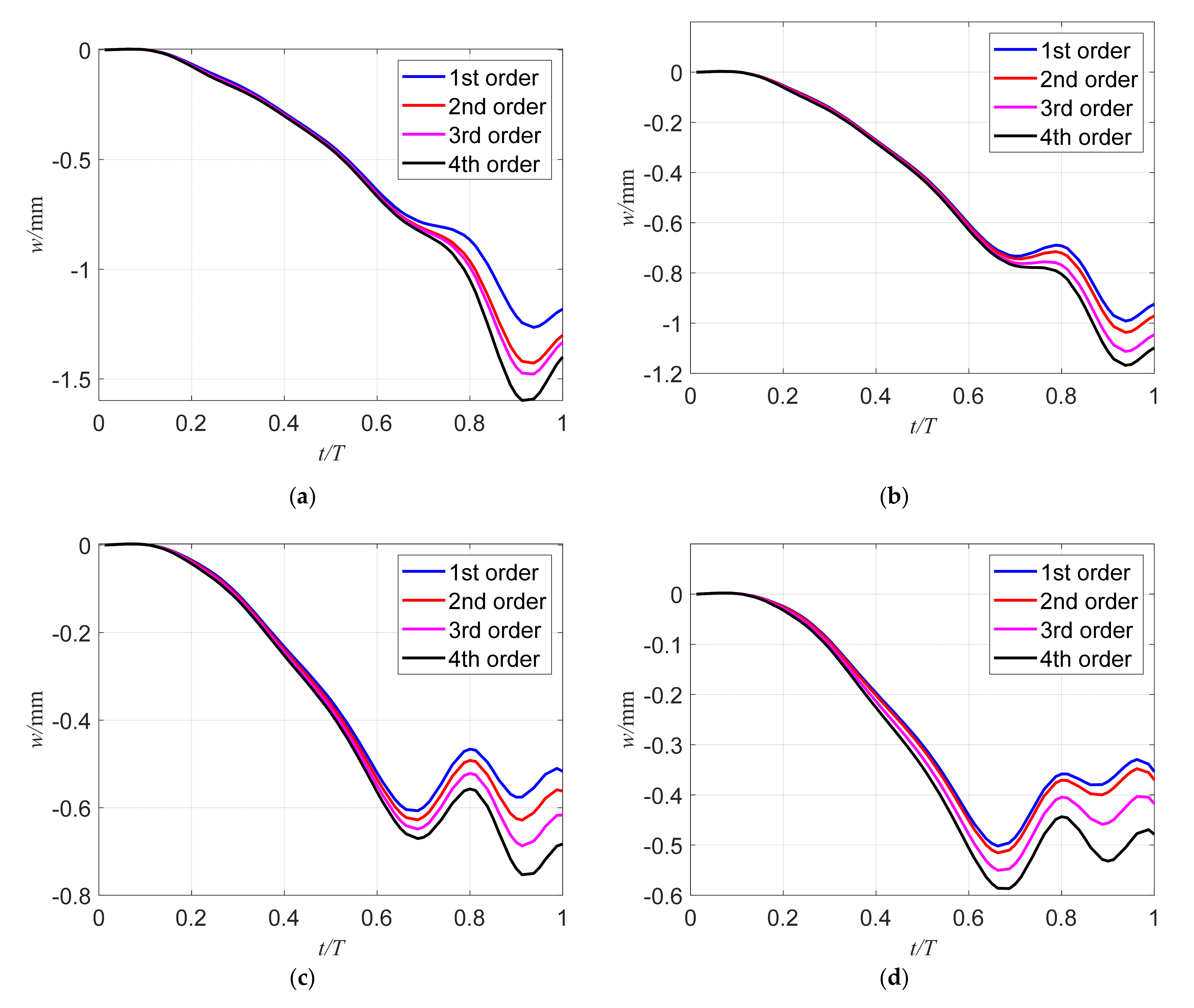
4.4.1. The Influence of Single Order Optimization on Dynamic Response

The purpose of optimizing the damping loss factor is to increase the absorption energy. That is to say, the dynamic response of the system decreases when the external force is applied. The focus of this paper is the dynamic response under moving loads. The load (F = 981 N) moves along a line (yL = W/2) of the partially cover plate at 50 m/s. In this section, the dynamic response of the partially covered plate with four kinds of patch sizes (0.04 m × 0.04 m, 0.08 m × 0.08m, 0.16 m × 0.16 m, 0.16 m × 0.04 m) for the CFFF condition after the first four order damping optimization under a moving load is investigated. Other parameters are the same as before. Figure 7a–d shows the dynamic responses of the center point of the partially covered plate with four kinds of patch sizes. Blue, red, pink and black solid lines represent the results of the first, second, third and fourth order damping optimizations, respectively. As shown in Figure 7a–d, with the increase in the coverage area, the dynamic response of the composite plate decreases accordingly. It shows that increasing the coverage area will increase the stiffness and damping of the system so as to resist the deformation caused by the moving force.
From Figure 7a–d, with the increase in the order of the optimized damping loss factor, the dynamic response of the system increases accordingly. From the optimization point of view, the best optimization strategy is to optimize the damping loss factor with a smaller order. It may be related to the dominant position of the low order loss factor in the system. At the same time, it will be found that this strategy will not change as the coverage size changes. Therefore, it can be concluded that no matter what the coverage size, the dynamic response of the system always decreases with the decrease in the order of the optimal damping loss factor.

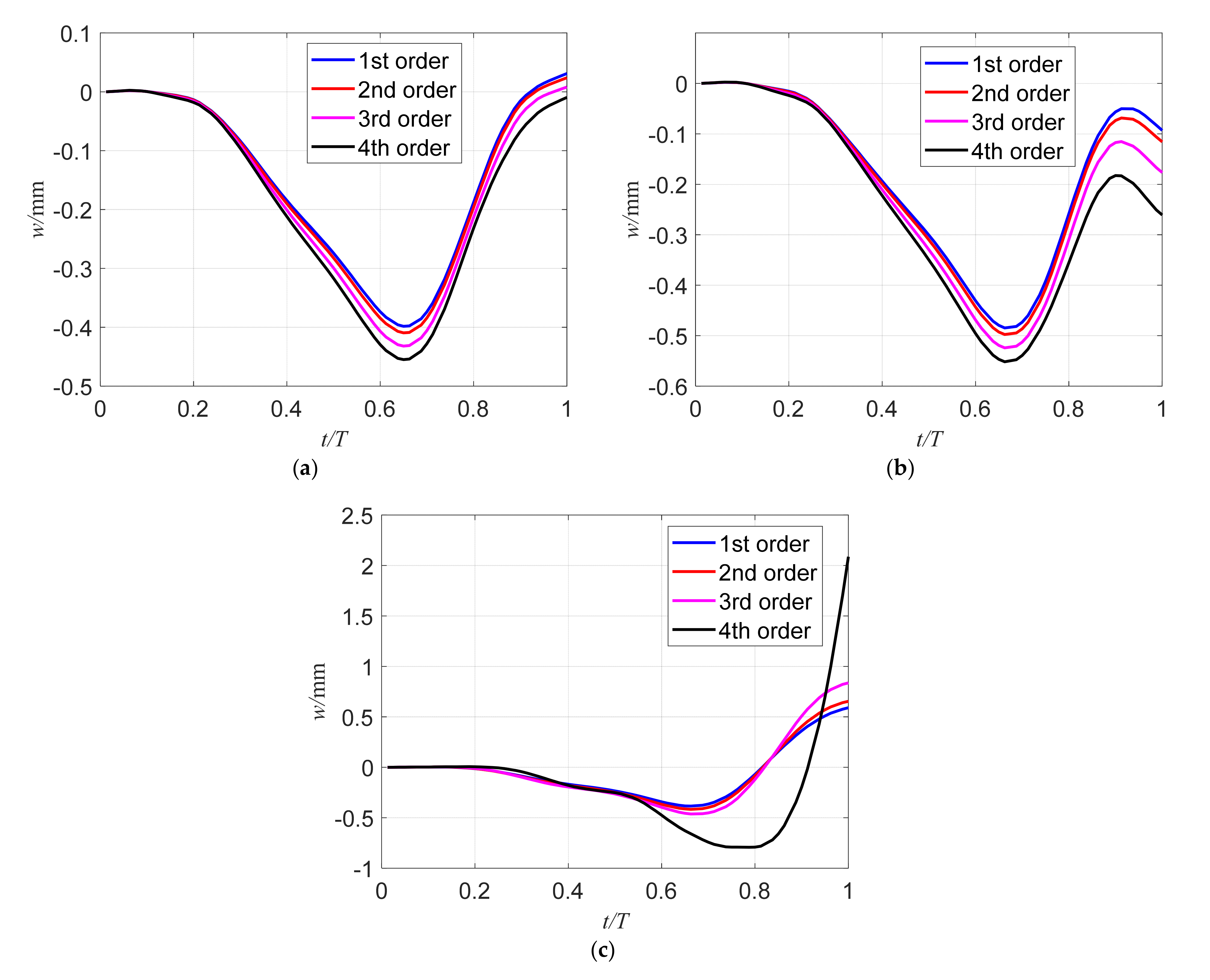
4.4.2. Dynamic Response of the Partially Covered Plate for Various Boundary Conditions

Under three boundary conditions (CFCF, SFSF CFSG), the response of the sandwich plate with an optimized first four order damping loss factor under moving loads is studied in this section. The load (F = 981 N) moves along a line (yL = W/2) of the partially covered plate at 50 m/s and the size of the patch is 0.08 m × 0.08 m. Other parameters are the same as before. Figure 8a–c shows the dynamic responses of the center point of the partially covered plate with patch size 0.08 m × 0.08 m after the first four order damping loss factor optimizations for CFFF, SFSF, CFSG. Blue, red, pink and black solid lines represent the results of the first, second, third and fourth order damping optimizations, respectively.
From Figure 8a–c, it is easy to see that the response of the system will decrease with the enhancement of boundary constraints. Meanwhile, the best optimization strategy is consistent with Section 4.4.1. Therefore, it can be concluded that the dynamic response of the system will decrease with the decrease in the order of the optimal damping loss factor, regardless of the boundary conditions of the system.

5. Conclusions

In this paper, the model of a partially covered plate under moving loads was established based on the Lagrange equation, and the optimization of the location of the patch is investigated by means of the proposed model. The main contributions of this study are listed as follows:
(1) The governing equations of the model are derived based on the first-order shear deformation theory, and the weight and inertia of the moving force are all taken into account. In order to make the convergence faster and more accurate, the trigonometric function and power function are used in the admissible function. At the same time, differential quadrature is used to solve the time domain of the system, which has high precision. Then, the numerical results are comprehensively verified by experiments and open literature. The error between the experimental and theoretical results is within the acceptable range. This proves the accuracy and convergence of the model proposed in this paper, and carries out the subsequent optimization research based on this model.
(2) In order to obtain the optimal damping loss factor, the problem is transformed as: the maximum damping loss factor is obtained when the local coverage size is constant. Therefore, this paper adopts a multi population genetic method, which has a high global optimization ability. The objective of the optimization function is the damping loss factor of the system, and the design variable is the coordinate of the patch (a, b, c, d). The result of the optimization shows that the location of the patch is close to the boundary of constraint, and the damping loss factor is larger. This can provide a good reference for engineering and academics.
(3) The time-domain response of the partially covered plate under the moving load is investigated after optimization in this paper. The influence of single order optimization on the damping loss factor and various boundary conditions can be seen through the comparison of optimization results under the different boundary conditions and coverage areas. It can be concluded that in order to reduce the dynamic response of the system under a moving load, the best optimization strategy is to optimize the lower order damping loss factor.
The method developed in this study is suitable for guiding the design of partially covered plates in engineering, and can give consideration to calculation accuracy and speed. The method is only limited to the calculation of linear materials. With nonlinear materials, it is difficult to ensure the accuracy of the results.

Author Contributions

Conceptualization, Y.Q., Q.S., and Z.L.; experiments and formal analysis, Y.Q. and J.S.; writing and visualization, Y.Q., Q.S., and Z.L. All authors have read and agreed to the published version of the manuscript.

Funding

This project was supported by the National Natural Science Foundation of China (no. 51,922,066), the Natural Science Outstanding Youth Fund of Shandong Province (Grant No. ZR2019JQ19), the United Fund of Ministry of Education for Equipment Pre-research (no. 6141A02022132), the Key Research and Development Plan of Shandong Province (Grant No. 2019JMRH0307), and the Natural Science Foundation of Shandong Province (Grant No. ZR2019MEE061).

Institutional Review Board Statement

Not applicable.

Informed Consent Statement

Not applicable.

Data Availability Statement

The data presented in this study are available upon request from the corresponding author.

Conflicts of Interest

The authors declare that they have no conflict of interest.

Appendix A

M 11 , u v = 0 L 0 W ρ b h b φ m φ n ψ i ψ j d x d y + a b c d ρ c h c + ρ d h d φ m φ n ψ i ψ j d x d y
M 11 , u v * = M φ m ( v M t ) φ n ( v M t ) ψ i ( y M ) ψ j ( y M )
C 11 , u v * = 2 M v M φ m ( v M t ) φ n , x ( v M t ) ψ i ( y M ) ψ j ( y M )
K 11 , u v = E c h c 3 12 1 μ c 3 a b c d φ m , x x φ n , x x ψ i ψ j + 2 1 μ c φ m , x φ n , x ψ i , y ψ j , y + φ m φ n ψ i , y y ψ j , y y + μ c φ m , x x φ n ψ i ψ j , y y + φ m φ n , x x ψ i , y y ψ j d x d y + G d h 2 h d 2 a b c d φ m , x φ n , x ψ i ψ j + φ m φ n ψ i , y ψ j , y d x d y + E b h b 3 12 1 μ b 3 0 L 0 W φ m , x x φ n , x x ψ i ψ j + 2 1 μ b φ m , x φ n , x ψ i , y ψ j , y + φ m φ n ψ i , y y ψ j , y y + μ b φ m , x x φ n ψ i ψ j , y y + φ m φ n , x x ψ i , y y ψ j d x d y
K 11 , u v * = M v M 2 φ m ( v M t ) φ n , x x ( v M t ) ψ i ( y M ) ψ j ( y M ) + φ m , x x ( v M t ) φ n ( v M t ) ψ i ( y M ) ψ j ( y M )
K 11 , u v = K 11 , u v ( 1 ) + K 11 , u v ( 2 ) + K 11 , u v ( 3 ) + K 11 , u v ( 4 )
K 11 , u v ( 1 ) = k z , t ( 1 ) φ m ( 0 ) φ n ( 0 ) 0 W ψ i ψ j d y + k z , r ( 1 ) φ m , x ( 0 ) φ n , x ( 0 ) 0 W ψ i ψ j d y
K 11 , u v ( 2 ) = k z , t ( 2 ) ψ i ( 0 ) ψ j ( 0 ) 0 L φ m φ n d x + k z , r ( 2 ) ψ i , y ( 0 ) ψ j , y ( 0 ) 0 L φ m φ n d x
K 11 , u v ( 3 ) = k z , t ( 3 ) φ m ( L ) φ n ( L ) 0 W ψ i ψ j d y + k z , r ( 3 ) φ m , x ( L ) φ n , x ( L ) 0 W ψ i ψ j d y
K 11 , u v ( 4 ) = k z , t ( 4 ) ψ i ( W ) ψ j ( W ) 0 L φ m φ n d x + k z , r ( 4 ) ψ i , y ( W ) ψ j , y ( W ) 0 L φ m φ n d x
K 12 , u v = G d h h d 2 a b c d φ m , x φ n ψ i ψ j d x d y
K 13 , u v = G d h h d 2 a b c d φ m φ n ψ i , x ψ j d x d y
K 14 , u v = G d h h d 2 a b c d φ m , x φ n ψ i ψ j d x d y
K 15 , u v = G d h h d 2 a b c d φ m φ n ψ i , x ψ j d x d y
K 22 , u v = E b h b 1 μ b 2 0 L 0 W φ m , x φ n , x ψ i ψ j + 1 μ b 2 φ m φ n ψ i , y ψ j , y d x d y + G d h d 2 a b c d φ m φ n ψ i ψ j d x d y
K 22 , u v = K 22 , u v ( 1 ) + K 22 , u v ( 2 ) + K 22 , u v ( 3 ) + K 22 , u v ( 4 )
K 22 , u v ( 1 ) = k x , t ( 1 ) φ m ( 0 ) φ n ( 0 ) 0 W ψ i ψ j d y + k x , r ( 1 ) φ m , x ( 0 ) φ n , x ( 0 ) 0 W ψ i ψ j d y
K 22 , u v ( 2 ) = k x , t ( 2 ) ψ i ( 0 ) ψ j ( 0 ) 0 L φ m φ n d x + k x , r ( 2 ) ψ i , y ( 0 ) ψ j , y ( 0 ) 0 L φ m φ n d x
K 22 , u v ( 3 ) = k x , t ( 3 ) φ m ( L ) φ n ( L ) 0 W ψ i ψ j d y + k x , r ( 3 ) φ m , x ( L ) φ n , x ( L ) 0 W ψ i ψ j d y
K 22 , u v ( 4 ) = k x , t ( 4 ) ψ i ( W ) ψ j ( W ) 0 L φ m φ n d x + k x , r ( 4 ) ψ i , y ( W ) ψ j , y ( W ) 0 L φ m φ n d x
K 23 , u v = E b h b 1 μ b 2 0 L 0 W μ b φ m , x φ n ψ i ψ j , y + 1 μ b 2 φ m φ n , x ψ i , y ψ j d x d y
K 24 , u v = G d h d 2 a b c d φ m φ n ψ i ψ j d x d y
K 33 , u v = E b h b 1 μ b 2 0 L 0 W φ m φ n ψ i , y ψ j , y + 1 μ b 2 φ m , x φ n , x ψ i ψ j d x d y + G d h d 2 a b c d φ m φ n ψ i ψ j d x d y
K 33 , u v = K 33 , u v ( 1 ) + K 33 , u v ( 2 ) + K 33 , u v ( 3 ) + K 33 , u v ( 4 )
K 33 , u v ( 1 ) = k y , t ( 1 ) φ m ( 0 ) φ n ( 0 ) 0 W ψ i ψ j d y + k y , r ( 1 ) φ m , x ( 0 ) φ n , x ( 0 ) 0 W ψ i ψ j d y
K 33 , u v ( 2 ) = k y , t ( 2 ) ψ i ( 0 ) ψ j ( 0 ) 0 L φ m φ n d x + k y , r ( 2 ) ψ i , y ( 0 ) ψ j , y ( 0 ) 0 L φ m φ n d x
K 33 , u v ( 3 ) = k y , t ( 3 ) φ m ( L ) φ n ( L ) 0 W ψ i ψ j d y + k y , r ( 3 ) φ m , x ( L ) φ n , x ( L ) 0 W ψ i ψ j d y
K 33 , u v ( 4 ) = k y , t ( 4 ) ψ i ( W ) ψ j ( W ) 0 L φ m φ n d x + k y , r ( 4 ) ψ i , y ( W ) ψ j , y ( W ) 0 L φ m φ n d x
K 35 , u v = G d h d 2 a b c d φ m φ n ψ i ψ j d x d y
K 44 , u v = E c h c 1 μ c 2 a b c d φ m , x φ n , x ψ i ψ j + 1 μ c 2 φ m φ n ψ i , y ψ j , y d x d y + G d h d 2 a b c d φ m φ n ψ i ψ j d x d y
K 45 , u v = E c h c 1 μ c 2 a b c d μ c φ m , x φ n ψ i ψ j , y + 1 μ c 2 φ m φ n , x ψ i , y ψ j d x d y
K 55 , u v = E c h c 1 μ c 2 a b c d φ m φ n ψ i , y ψ j , y + 1 μ c 2 φ m , x φ n , x ψ i ψ j d x d y + G d h d 2 a b c d φ m φ n ψ i ψ j d x d y
F z , k ( t ) = M g φ i ( x M ) ψ j ( y M ) + f z ( t ) φ i ( x F ) ψ j ( y F )
F x , k ( t ) = f x ( t ) φ i ( x F ) ψ j ( y F )
F y , k ( t ) = f y ( t ) φ i ( x F ) ψ j ( y F )
In Equations (A1)–(A35), u = m + ( i − 1) × N, v = n + (j − 1) × N and k = j + (i − 1) × N, where i, j, m and n = 1, 2, …, N.

References

  1. Kerwin, E.M., Jr. Damping of flexural waves by a constrained viscoelastic layer. J. Acoust. Soc. Am. 1959, 31, 952–962. [Google Scholar] [CrossRef]
  2. Mead, D.J.; Markus, S. The forced vibration of a three-layer, damped sandwich beam with arbitrary boundary conditions. J. Sound Vib. 1969, 10, 163–175. [Google Scholar] [CrossRef]
  3. Johnson, C.D.; Keinholz, D.A. Finite element prediction of damping in structures with constrained viscoelastic layers. AIAA J. 1982, 20, 1284–1290. [Google Scholar] [CrossRef]
  4. Lall, A.K.; Asnani, N.T.; Nakra, B.C. Vibration and damping analysis of rectangular plate with partially covered constrained viscoelastic layer. J. Vib. Acoust. Stress Reliab. Des. 1987, 109, 241–247. [Google Scholar] [CrossRef]
  5. Cupial, P.; Niziol, J. Vibration and damping analysis of a three-layered composite plate with a viscoelastic mid-layer. J. Sound Vib. 1995, 183, 99–114. [Google Scholar] [CrossRef]
  6. Wang, G.; Veeramani, S.; Wereley, N.M. Analysis of sandwich plates with isotropic face plates and a viscoelastic core. J. Vib. Acoust. 2000, 122, 305–312. [Google Scholar] [CrossRef]
  7. Banerjee, J.R.; Cheung, C.W.; Morishima, R.; Perera, M.; Njuguna, J. Free vibration of a three-layered sandwich beam using the dynamic stiffness method and experiment. Int. J. Solids Struct. 2007, 44, 7543–7563. [Google Scholar] [CrossRef] [Green Version]
  8. Ferreira, A.J.M.; Araujo, A.L.; Neves, A.M.A.; Rodrigues, J.D.; Carrera, E.; Cinefra, M.; Soares, C.M.M. A finite element model using a unified formulation for the analysis of viscoelastic sandwich laminates. Compos. Part B Eng. 2013, 45, 1258–1264. [Google Scholar] [CrossRef] [Green Version]
  9. Khalfi, B.; Ross, A. Transient response of a plate with partial constrained viscoelastic layer damping. Int. J. Mech. Sci. 2013, 68, 304–312. [Google Scholar] [CrossRef]
  10. Hernandez, W.P.; Castello, D.A.; Ritto, T.G. Uncertainty propagation analysis in laminated structures with viscoelastic core. Comput. Struct. 2016, 164, 23–37. [Google Scholar] [CrossRef]
  11. Kazeminia, M.; Soleimani-Amiri, S.; Zahedi, S.A. Exact and numerical solutions for nonlinear higher order modified KdV equations by using variational iteration method. Adv. Stud. Theor. Phys. 2010, 4, 437–447. [Google Scholar]
  12. Fazeli, M.; Zahedi, S.A.; Tolou, N. Explicit Solution of Non-Linear Fourth-Order Parabolic Equations via Homotopy Perturbation Method. J. Appl. Sci. 2008, 8, 2619–2624. [Google Scholar] [CrossRef] [Green Version]
  13. Kazemnia, M.; Zahedi, S.A.; Vaezi, M.; Tolou, N. Assessment of Modified Variational Iteration Method in BVPs High-Order Differential Equations. J. Appl. Sci. 2008, 8, 4192–4197. [Google Scholar] [CrossRef] [Green Version]
  14. Zahedi, S.A.; Babitsky, V. Modeling of autoresonant control of a parametrically excited screen machine. J. Sound Vib. 2016, 380, 78–89. [Google Scholar] [CrossRef]
  15. Mantena, P.R.; Gibson, R.F.; Hwang, S.J. Optimal constrained viscoelastic tape lengths for maximizing dampingin laminated composites. AIAA J. 1991, 29, 1678–1685. [Google Scholar] [CrossRef]
  16. Marcelin, J.-L.; Trompette, P.; Smati, A. Optimal constrained layer damping with partial coverage. Finite Elem. Anal. Des. 1992, 12, 273–280. [Google Scholar] [CrossRef]
  17. Ro, J.; Baz, A. Optimum placement and control of active constrained layer damping using modal strain energy approach. Modal Anal. 2002, 8, 861–876. [Google Scholar] [CrossRef]
  18. Zheng, H.; Cai, C.; Pau, G.S.H.; Liu, G.R. Minimizing vibration response of cylindrical shells through layout optimization of passive constrained layer damping treatments. J. Sound Vib. 2005, 279, 739–756. [Google Scholar] [CrossRef]
  19. Lepoittevin, G.; Kress, G. Optimization of segmented constrained layer damping with mathematical programming using strain energy analysis and modal data. Mater. Des. 2010, 31, 14–24. [Google Scholar] [CrossRef]
  20. Zheng, W.; Lei, Y.; Li, S.; Huang, Q. Topology optimization of passive constrained layer damping with partial coverage on plate. Shock Vib. 2013, 20, 199–211. [Google Scholar] [CrossRef]
  21. Kumar, A.; Panda, S.; Narsaria, V.; Kumar, A. Augmented constrained layer damping in plates through the optimal design of a 0-3 viscoelastic composite layer. J. Vib. Control 2018, 24, 5514–5524. [Google Scholar] [CrossRef]
  22. Nakra, B.C. Structural dynamic modification using additive damping. Sadhana 2000, 25, 277–289. [Google Scholar] [CrossRef] [Green Version]
  23. Marcelin, J.-L.; Shakhesi, S.; Pourroy, F. Optimal constrained layer damping of beams: Experimental and numerical studies. Shock Vib. 1995, 2, 445–450. [Google Scholar] [CrossRef]
  24. Zheng, H.; Cai, C.; Tan, X.M. Optimization of partial constrained layer damping treatment for vibrational energy minimization of vibrating beams. Comput. Struct. 2004, 82, 2493–2507. [Google Scholar] [CrossRef]
  25. Araújo, A.L.; Mota-soares, C.M.; Mota-soares, C.A.; Herskovits, J. Optimal design and parameter estimation of frequency dependent viscoelastic laminated sandwich composite plates. Compos. Struct. 2010, 92, 2321–2327. [Google Scholar] [CrossRef]
  26. Hou, S.; Jiao, Y.; Chen, Z. Optimum layout of passive constrained layer damping treatment using genetic algorithms. In Proceedings of the ASME 2010 International Mechanical Engineering Congress and Exposition, Vancouver, BC, Canada, 12–18 November 2010; American Society of Mechanical Engineers: New York, NY, USA, 2010. [Google Scholar]
  27. Pathan, M.V.; Patsias, S.; Tagarielli, V.L. A real-coded genetic algorithm for optimizing the damping response of composite laminates. Comput. Struct. 2018, 198, 51–60. [Google Scholar] [CrossRef]
  28. Sun, W.; Liu, R.; Fan, Y. Analytical modeling and damping optimization for a thin plate partially covered with hard coating. Arch. Appl. Mech. 2018, 88, 897–912. [Google Scholar] [CrossRef]
  29. Gao, F.; Sun, W.; Gao, J. Optimal design of the hard-coating blisk using nonlinear dynamic analysis and multi-objective genetic algorithm. Compos. Struct. 2019, 208, 357–366. [Google Scholar] [CrossRef]
  30. Frýba, L. Vibration of Solids and Structures under Moving Loads; Springer Science & Business Media: New York, NY, USA, 2013; Volume 1. [Google Scholar]
  31. Gbadeyan, J.A.; Oni, S.T. Dynamic behaviour of beams and rectangular plates under moving loads. J. Sound Vib. 1995, 182, 677–695. [Google Scholar] [CrossRef]
  32. Kim, S.-M.; McCullough, B.F. Dynamic response of plate on viscous Winkler foundation to moving loads of varying amplitude. Eng. Struct. 2003, 25, 1179–1188. [Google Scholar] [CrossRef]
  33. Wu, J.-J. Vibration of a rectangular plate undergoing forces moving along a circular path. Finite Elem. Anal. Des. 2003, 40, 41–60. [Google Scholar] [CrossRef]
  34. Lee, S.-Y.; Yhim, S.-S. Dynamic analysis of composite plates subjected to multi-moving loads based on a third order theory. Int. J. Solids Struct. 2004, 41, 4457–4472. [Google Scholar] [CrossRef]
  35. Ghafoori, E.; Asghari, M. Dynamic analysis of laminated composite plates traversed by a moving mass based on a first-order theory. Compos. Struct. 2010, 92, 1865–1876. [Google Scholar] [CrossRef]
  36. Amiri, J.V.; Ali, N.; Reza, D.M.; Ebrahimzadeh, H.M. Vibration analysis of a Mindlin elastic plate under a moving mass excitation by eigenfunction expansion method. Thin-Walled Struct. 2013, 62, 53–64. [Google Scholar] [CrossRef]
  37. Esen, I. A new finite element for transverse vibration of rectangular thin plates under a moving mass. Finite Elem. Anal. Des. 2013, 66, 26–35. [Google Scholar] [CrossRef]
  38. Malekzadeh, P.; Monajjemzadeh, S.M. Dynamic response of functionally graded plates in thermal environment under moving load. Compos. Part B Eng. 2013, 45, 1521–1533. [Google Scholar] [CrossRef]
  39. Song, Q.; Liu, Z.; Shi, J.; Wan, Y. Parametric study of dynamic response of sandwich plate under moving loads. Thin-Walled Struct. 2018, 123, 82–99. [Google Scholar] [CrossRef]
  40. Shi, J.; Song, Q.; Liu, Z.; Ai, X. Partial Surface Damper to Suppress Vibration for Thin Walled Plate Milling. Chin. J. Mech. Eng. 2017, 30, 632–643. [Google Scholar] [CrossRef]
Figure 1. Model of system; (a) front view; (b) left view.
Applsci 11 03282 g001
Figure 2. Displacement of the sandwich plate in x-z plane.
Applsci 11 03282 g002
Figure 3. Research structure of this paper.
Applsci 11 03282 g003
Figure 4. Structure of multi-population genetic algorithms.
Applsci 11 03282 g004
Figure 5. Experimental composite plate.
Applsci 11 03282 g005
Figure 6. Optimal location of the patch for CFFF. (a) optimization for first order loss factor; (b) optimization for second order loss factor; (c) optimization for third order loss factor; (d) optimization for fourth order loss factor.
Applsci 11 03282 g006
Figure 7. Dynamic response of the partially covered plate with different patch sizes after first four order damping loss factor optimization for CFFF. (a) 0.04 m × 0.04 m; (b) 0.08 m × 0.08 m; (c) 0.16 m × 0.04 m; (d) 0.16 m × 0.16 m.
Applsci 11 03282 g007
Figure 8. Dynamic response of partially covered plate with patch size 0.08 m × 0.08 m after the first four order damping loss factor optimizations for CFFF, SFSF, CFSG. (a) CFCF; (b) SFSF; (c) CFSG.
Applsci 11 03282 g008
Table 1. First mode natural frequency and loss factor of the partially covered sandwich plate.
Patches SizeNatural Frequencies, rad/sLoss Factors
Present MethodNakra [22]Present MethodNakra [22]
PL = 0.15 PW = 0.15930.90930.800.003040.00300
PL = 0.39 PW = 0.06952.07952.100.007840.00770
Table 2. Material and geometric parameters of composite plates.
ParametersBase PlateDamping LayerConstrained Layer
Length L/m0.250.080.08
Width W/m0.250.080.08
Height h/m0.0040.0040.004
Density ρ/(g·cm−3)2.720.602.72
Elasticity modulus /GPa69.31269.3
Poisson ratio μ0.330.330.33
Loss factor η/0.25/
Table 3. The first four order natural frequencies of the sandwich plate obtained by the presented method and experiment (Hz).
OrderTheoretical Calculation (T)Experiment Result (E)Error
|T−E|/E (%)
159.5357.453.62
2142.21137.353.40
3348.74343.621.49
4437.47431.541.37
Table 4. The first four order damping loss factor of the sandwich plate obtained by the presented method and experiment.
OrderTheoretical Calculation
(T) (%)
Experiment Result (E)
(%)
Error
|T-E|/E (%)
10.1960.1884.23
20.1390.1325.30
30.0870.0925.43
40.0600.0567.14
Table 5. The parameters of multi population genetic algorithm (MPGA).
Parameters.Value
Number of individuals40
Precision of variables20
Population size10
Cross probability0.7
Mutation probability0.05
Table 6. The first four loss factors after optimizing the location of the patch for CFFF.
Figure number1st Order2nd Order3rd Order4th Order
Figure 6a0.040770.028640.012390.0011
Figure 6b0.040690.030950.013530.0008
Figure 6c0.040280.027530.014920.0125
Figure 6d0.039460.027040.014510.0169
Table 7. The first four loss factors after optimizing the location of the patch for CFCF, SFSF, CGSF.
BoundaryCoordinates of the Patch (x, y) and Loss Factors η
Condition1st Order2nd Order3rd Order4th Order
CFCF(0, 0.066)(0.32, 0.275)(0, 0.161)(0.32, 0.16)
0.004440.004330.006180.00248
SFSF(0, 0)(0, 0)(0.32, 0.16)(0, 0.16)
0.013380.009210.007800.00360
CGSF(0, 0.32)(0, 0.32)(0, 0.176)(0, 0.160)
0.009710.007590.007160.00335
Table 8. Optimization results with different patch sizes for CFFF.
Patch SizesCoordinates of the Patch (x, y) and Loss Factors η
1st Order2nd Order3rd Order4th Order
0.04 m × 0.04 m(0.144, 0.352)(0.182, 0.36)(0.309, 0.36)(0, 0.36)
0.012110.009690.004460.00576
0.16 m × 0.16 m(0.118, 0.217)(0.12, 0.24)(0.24, 0.24)(0, 0.24)
0.106250.079220.037440.03131
0.04 m × 0.16 m(0.181, 0.24)(0.212, 0.24)(0.36, 0.24)(0, 0.24)
0.040530.025660.011860.01455
Publisher’s Note: MDPI stays neutral with regard to jurisdictional claims in published maps and institutional affiliations.

