
Short-Term Analysis of Adhesive Types and Bonding Mistakes on Bonded-in-Rod (BiR) Connections for Timber Structures


1
Faculty of Civil Engineering, University of Zagreb, 10000 Zagreb, Croatia
2
Department of Engineering and Architecture, University of Trieste, 34127 Trieste, Italy
3
Department of Mechanical and Production Engineering, Aarhus University, 8000 Aarhus, Denmark
*
Author to whom correspondence should be addressed.
Appl. Sci. 2021, 11(6), 2665; https://doi.org/10.3390/app11062665
Submission received: 16 February 2021
/
Revised: 13 March 2021
/
Accepted: 15 March 2021
/
Published: 17 March 2021
(This article belongs to the Special Issue Buildings and Structures under Extreme Loads II)
Abstract
:Bonded-in rods (BiR) represent a structural connection type that is largely used for new timber structures and rehabilitation (repair or reinforcement) of existing structural members. The technology is based on steel / Fiber Reinforced Polymer (FRP) / Glass Fiber Reinforced Polymer (GFRP) rods bonded into predrilled holes in timber elements. The mechanical advantages of BiRs include high local force capacity, improved strength, a relatively high stiffness and the possibility of ductile behaviour. They also offer aesthetic benefits, given that rods are hidden in the cross sections of wooden members. As such, BiR connections are regarded as a solution with great potential, but still uncertain design formulations. Several research projects have dealt with BiRs, but a final definition of their mechanics and a universal design procedure is still missing. This research study explores the typical fracture mechanics modes for BiR connections. A special focus is given to the evaluation of the impact of adhesive bonds under various operational conditions (i.e., moisture content of timber). A total of 84 specimens are tested in pull-out setup, and investigated with the support of digital image correlation (DIC). The reliability of empirical equations and a newly developed analytical model in support of design, based on linear elastic fracture mechanics (LEFM), is also assessed.
1. Introduction
Glued-in rod (GiR) or bonded-in rod (BiR) connections are increasingly used in construction of timber structures [1], and so far several researchers addressed the mechanical performance of specific solutions of technical use in buildings.
Owning to their versatility, BiR connections are used extensively, and thus the need for proper assessment of their mechanical properties and standardized assembling procedures is ever increasing [2,3]. Research efforts have been spent to offer an accurate detail on BiR connections behaviour, but mainly for limited applications that can be hardly generalized. In this framework, most of the literature involving experimental studies have been focused on the axial pull-out strength of a single BiR connection, and its dependency on geometrical and material parameters. Examples can be found in [4,5,6,7,8,9,10] for various configurations, with a focus on the experimental assessment of various failure mechanisms [4], test protocols [5] or monotonic and cyclic loading [8]. Often, Finite Element numerical modelling techniques are applied to bonded joints in timber engineering [11,12,13,14]. Various experimental studies have been carried out with the additional goal of proposition and validation, as well as assessment of existing methods, of empirical formulations in support of design [15,16,17], based on curve-fitting of experimental outcomes. In this regard, the current study further explores the mechanical behaviour and properties of BiR connections for timber applications, but with a special focus on the effects due to different adhesive types and their operational condition. It is nowadays well recognized that both the environment conditions and the loading configuration severely affect the adhesive properties and thus the mechanical performance of BiR joints [18,19,20]. Further, the current investigation aims at finding a link between the proposed fracture mechanics failure modes [21] for BiR connections and the impact of adhesive sensitivity to service conditions.
In this paper, original pull-out experiments are carried out on a total of 84 BiR specimens, characterized by different adhesive types (epoxy or polyurethane glue), rod-to-grain arrangements (parallel or perpendicular), and average moisture content in timber (9%, 18% or 27% respectively, see also Table 1). The experimental results are discussed, with a focus on the load-bearing mechanism, fracture mechanisms and BiR performance analysis using simple empirical formulations of literature. Later on, a more refined analytical model is presented, and further assessed against the available experimental data.
2. Problem Definition
Connections and reinforcements with bonded-in rods have been used in building for several decades. For instance, this solution appeared for the first time in 1980, in French historical monuments [22]. Besides, adhesive bonds for timber applications are notoriously sensitive to several aspects, including:
- (1)
- wetting ability of the adhesive in relation to the surface;
- (2)
- bulk properties of adhesive after complete hardening;
- (3)
- severe environmental conditions.
(Point 1) relates to the substrate (type of surface, its treatment, any kind of ageing and chemical modification, etc.), and to the adhesive in use (viscosity, density, chemical affinity with the substrate, etc.). (Point 2) is particularly relevant when the thickness is high (as usual for structural applications in timber buildings). Finally, environment conditions in 3) can include elevated thermal distortions (due to fires or repeated hygrometric variations), such as wood deformations that induce additional coactive stress at the interface between the adhesive and timber.
From a practical point of view, the applied bond strength design values and the explicit strength modification factors are in most cases not retrievable. This is closely related to the fact that the current lack of worldwide standards or commonly accepted specifications exist for assessing and approving adhesives to be used for BiR applications. It is obvious from a chemistry view point that different adhesive types, which may have rather similar short-term bond strengths, can behave differently under variable climates. The design of BiR joints is implemented in European prestandards and technical documents [23,24,25], which specify the modification factors for accumulated duration of load in different climates (service classes in Table 1, as described in [26]). The final result takes the form of the well-known kmod factor. On the other hand, this factor is irrespective of the adhesive type.
The current investigation presents experimental tests of BiR connections in different humid climates, in order to explore their actual load-bearing capacity (strength and slip modulus, failure mechanism), as a function of two different adhesive types and rod arrangements.
3. Experimental Investigation
3.1. Test Specimens and Materials
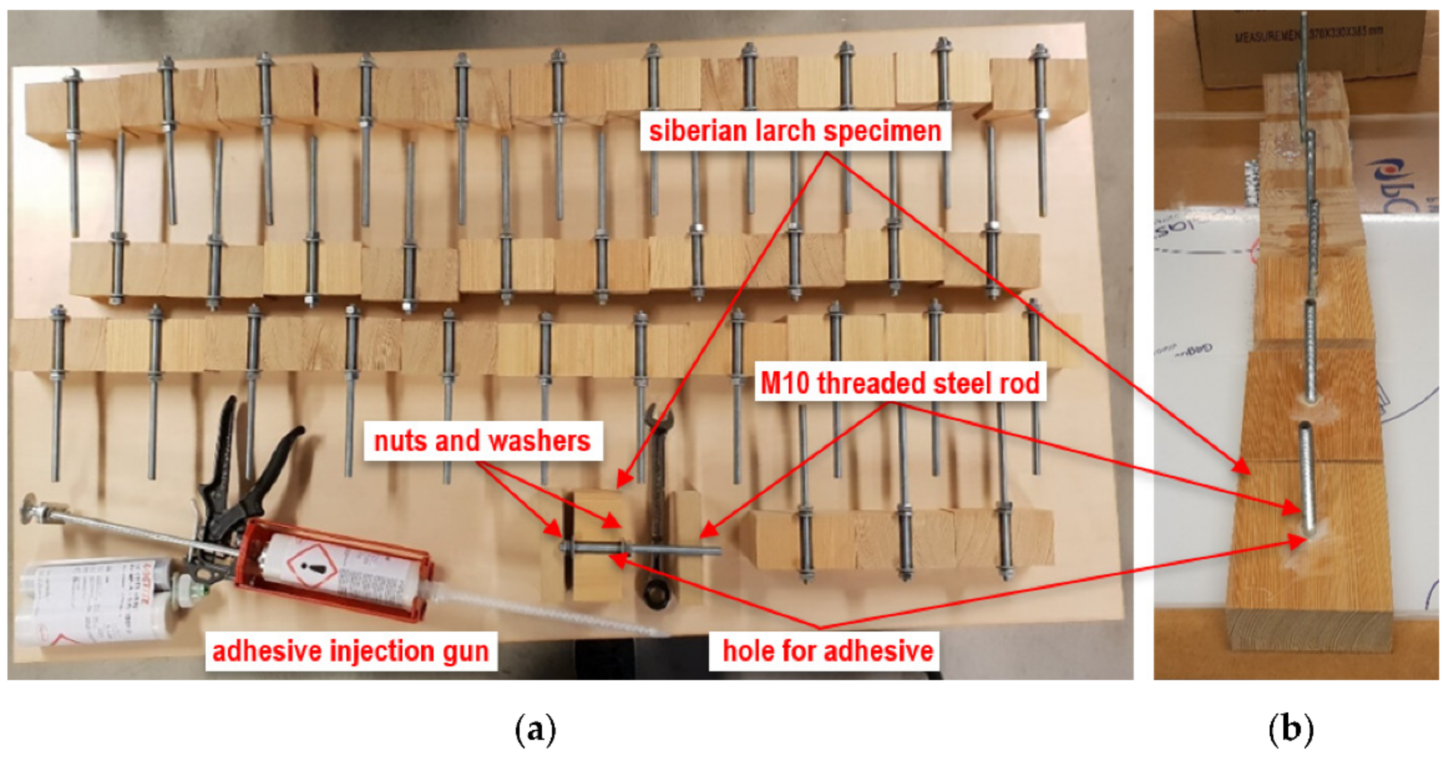
In order to gain a better insight into the behaviour of the joint, an extended series of experimental tests was carried out. In total, 84 specimens were taken into account in the laboratory investigation, with 72 “half-size” and 12 “standard” specimens. Among the half-size specimens, 36 samples were tested parallel and 36 perpendicular to the grains of timber. Furthermore, 12 full-size specimens tested to confirm the observed correlation between half-size and standard specimens (Figure 1).
Half-size specimens (with dimensions B = 120/W = 60/L = 60 mm) were drilled in their full height L with a concave-notch diameter equal to dh = 14 mm. This hole was placed at the centre of the cross-section of each timber log, in order to introduce both the rod and the adhesive bond. Standard type specimens were characterized by double size (with dimensions B = 120/W = 120/L = 60 mm) and prepared with a similar approach. Each timber log was drilled in the full height (60 mm), and a dh = 14 mm hole was drilled at the centre of the wood cross-area.
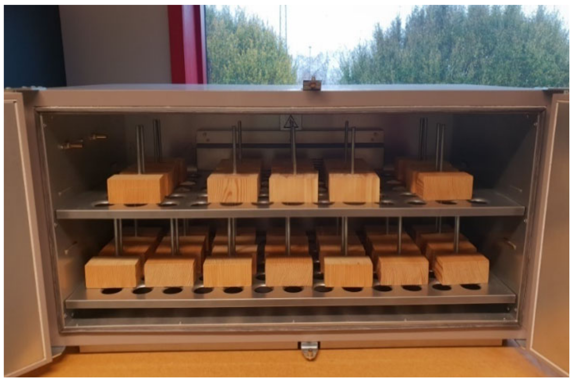
To get the results for the highest service class, Siberian larch (Larix sibirica) wood was used for the timber components [27]. After three weeks in a climate enclosure room with a controlled atmosphere, the moisture content was around 12% (Figure 2). The measured average density was close to 600 kg/m3, with a standard deviation of 25 kg/m3.
One standard metrically threated steel rod with 8.8 strength, nominal diameter d = 10 mm and total length of 200 mm was bonded in each wooden specimen (L = 60 mm the bonded length). The bonding effect was investigated with two different adhesive types, being represented by a two-component epoxy (KGK EPOCON ‘88) and a two-component polyurethane (LOCTITE PUREBOND CR 821). Table 2 summarizes the nominal mechanical properties of materials.
Based on the M10 rod in use and the dh mm hole, an annular bond-line thickness of 2 mm was created for each sample, and the anchorage length was set equal to H = 60 mm. The bonding stage was performed under controlled laboratory conditions (9% humidity in wood and a room temperature of 20 °C, see Figure 1).
3.2. Test Setup and Instruments
After the assembly process, all the specimens were subjected to a controlled atmosphere, so as to achieve different degrees of moisture in wood (at the same temperature of 20 °C). The experiments reported herein comprised three artificial climates being selected as extreme examples of operational conditions for service class 1, 2 and 3 (Table 1). All test series were in fact performed at a constant temperature of 20 °C, with moisture content in wood in the order of 9%, 18% and 27% respectively.
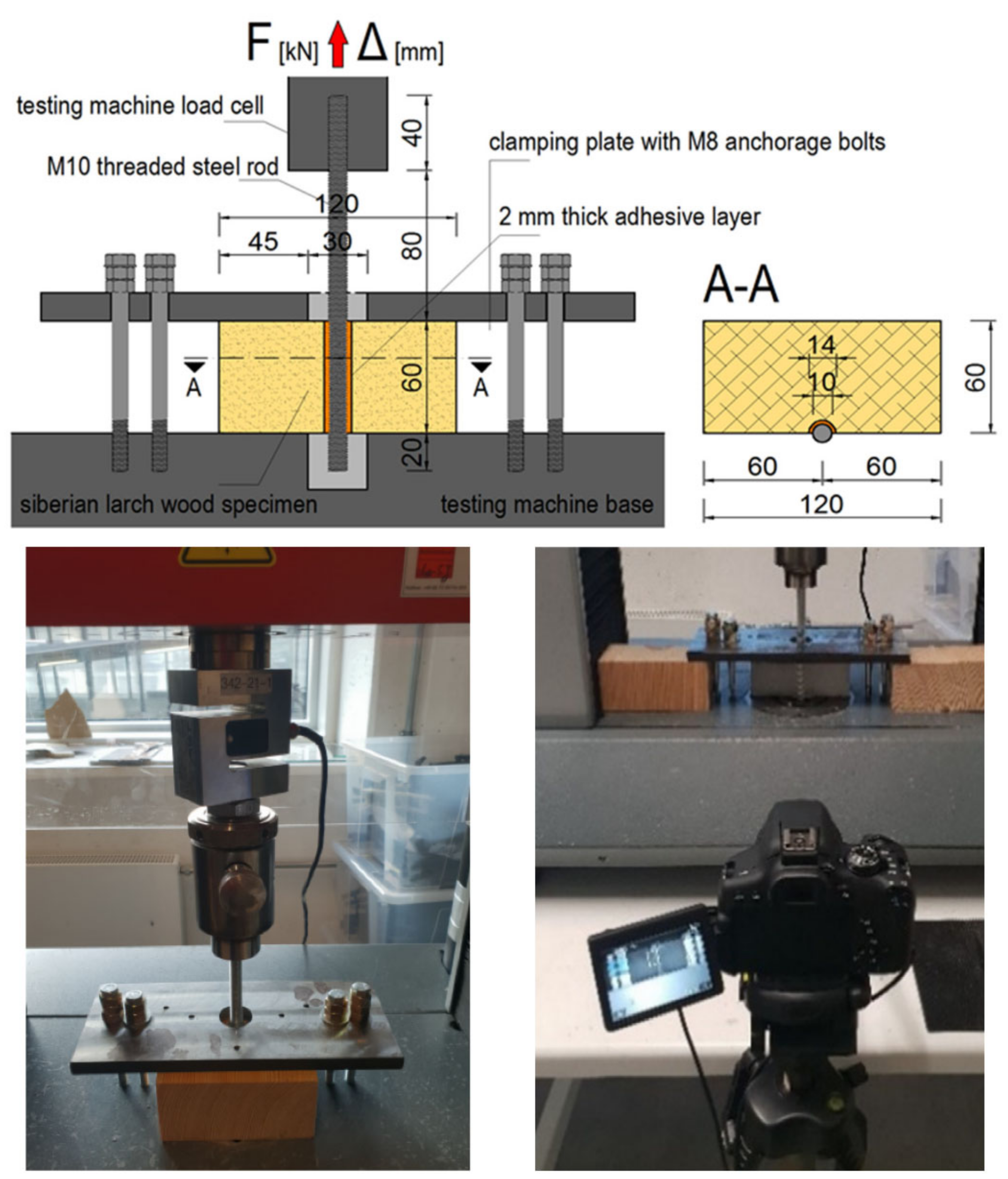
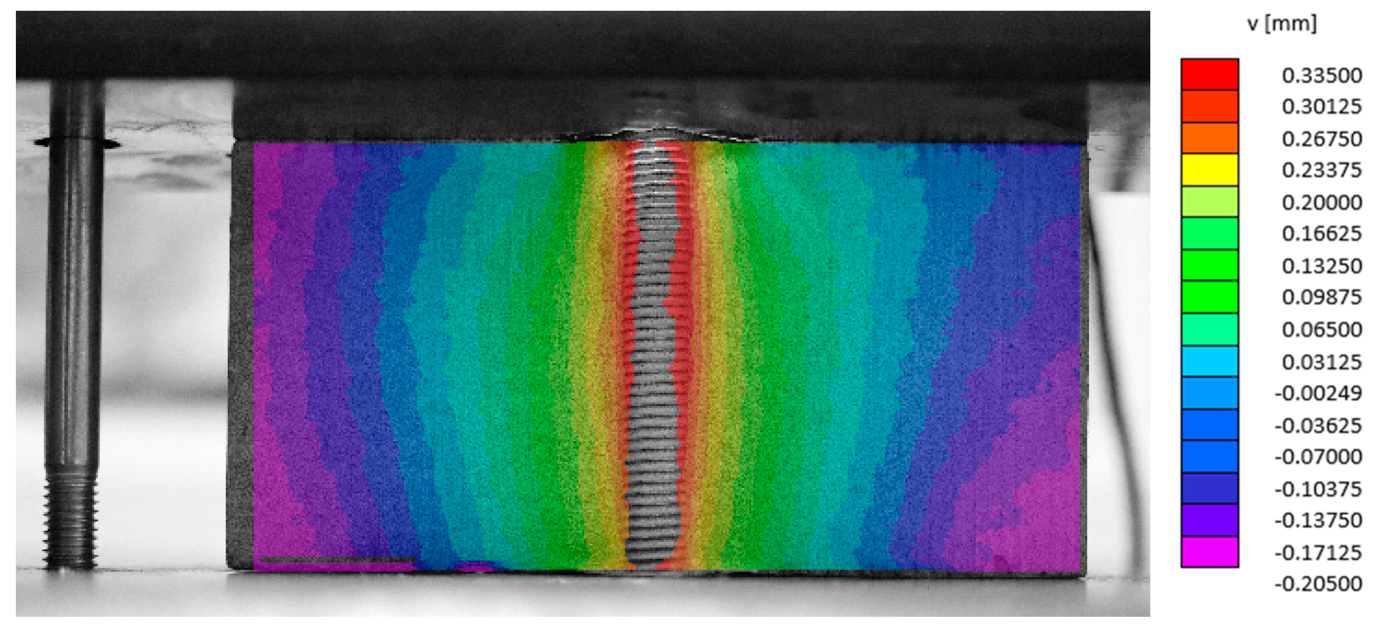
The stiffness and strength characteristics in short-term loading were thus investigated according to EN 15274:2015 recommendations [28]. Further, all tests were carried out based on the EN1382:2016 provisions [29], on a Zwick Roell 50 kN capacity machine, with data recording frequency of 10 Hz. The reference pull-out setup is shown in Figure 3. Each specimen was fixed to the machine with a steel clamping plate. Possible relative displacements of wood logs were restrained by four M8 anchoring bolts. The single rod was hence clamped to the pull machine. To this aim, the nominal cross-head displacement rate was set to ensure a reference value of 0.5–2.0 mm/min (depending on specimen type). The latter was then calibrated (test by test) in order to reproduce a short-term failure mechanism for all the specimens. The axial load F applied to each specimen was recorded and compared with the average relative displacement of the rod with respect to the wood log. In support of these experimental investigations, contactless optical measurements of strain (based on digital image correlation (DIC) techniques), were also implemented to provide full-field strain maps of specimens under load, until failure. The experiments of 24 specimens were further supported by a Canon 700D camera with macro lens and photo recording frequency of 0.5 Hz (Figure 3). All specimens had preprepared surface adapted for recording. The whole postprocessing stage of acquired images was carried out by VIC-2D (Correlated Solutions, University Santa Barbara, Santa Barbara, CA, USA). This approach was used to reveal local aspects of load transfer mechanisms from the rod to the adhesive and wood that could be of importance for further analysis using theoretical or even numerical models.
3.3. Test Results
The analysis of experimental results was carried out at different levels, including (a) qualitative analysis of observed failure mechanisms, (b) measured load-displacement laws, (c) DIC measurement of displacements in the bonded region.
For sake of clarity, the specimens are labelled to detect the type of glue (“E” or “P” for epoxy and polyurethane), the moisture content (9%, 18% or 27%), the rod-to-grain orientation (“0°” or “90°” for parallel or perpendicular arrangement) and the sample number n for each group. The full set of pull-out test results is presented in Appendix A.
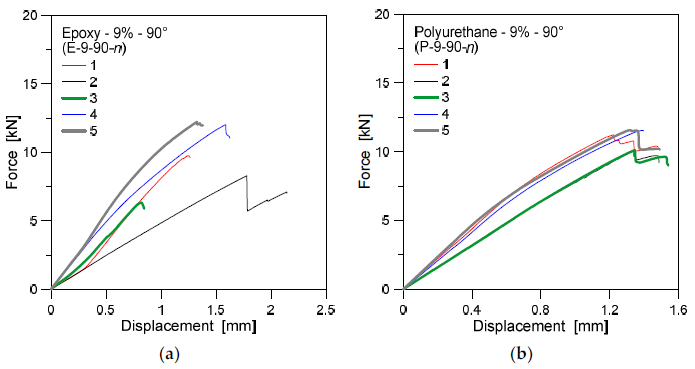
Three regimes can be distinguished from the collected load-displacement curves, as shown in the examples of Figure 4 and Figure 5 (specimens under 9% moisture and load parallel or perpendicular to the grain, respectively).
Firstly, a linear elastic stage can be noticed in the load-bearing response of all the specimens, from which the initial stiffness Kser = Fax/d can be estimated from a linear regression procedure.
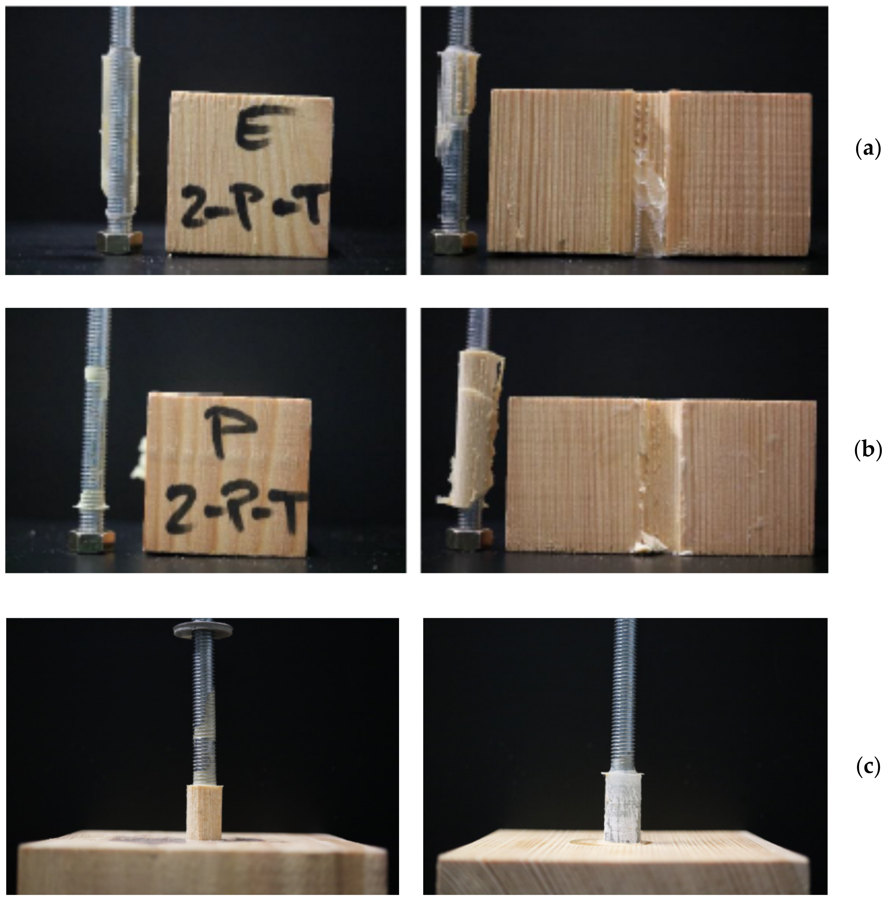
After the yield point, a progressive decrease of stiffness occurs followed by a sudden failure of the connection. Worth to be noted, in this regard, that the failure path of all tested connections was located in the wood substrate in the vicinity of the wood–adhesive interface, as also emphasized in Figure 6. Thus, the nonlinearity observed in the collected force–displacement responses can be rationally justified in the quasibrittle damage of wood.
Finally, the ultimate load measurement for the experimental curves as in Figure 4 and Figure 5 allows estimating the overall shear strength of the examined connections. Following Figure 6 and that the failure mechanism of BiRs is dependent on the mechanical properties of solid wood (strength and stiffness), the typical collapse of BiRs can be assumed as quasi-brittle for general applications.
More in detail, for rods bonded parallel to the grains, wood failure was observed to start in the area around the adhesive matrix, while for rods bonded perpendicularly to the grains, failure typically originated in line between adhesive matrix and wood (Figure 6). The qualitative observations at failure, for a selection of specimens, were further explored by DIC system as in Figure 7.
Average values of maximum force (Fmax) and displacement (dmax), as well as of slip modulus (shear stiffness Kser) and their corresponding coefficient of variation (CoV.) and standard deviation (St.Dev.) are listed in Table 3 and Table 4. Major scatter of grouped predictions is found for the “9%” set in Table 4, which was found characterized by 36% CoV. in terms of slip modulus. On the other side, such an experimental outcome was severely affected by few specimens (like specimen #2 in Figure 5a).
Considering the specimens grouped by adhesive type, from Table 3 and Table 4 it is possible to notice a less pronounced sensitivity and scatter of polyurethane bonded rods, compared to the epoxy bonded samples. This effect is even more pronounced for service classes 2 and 3, with higher moisture content.
Mean experimental data can be helpful for the analysis of climate and operational conditions on bonded rods for timber applications. However, an in-depth discussion can be carried out in terms of characteristic mechanical properties that can be obtained from the test observations.
Based on [28], the characteristic axial force at failure for each series of specimens was calculated as:
with:
where n denotes the number of test repetitions for each series, ks is a coefficient adopted from [28].
Furthermore, the maximum axial force at failure (both in terms of mean and characteristic values) was correlated with the resisting surface of the bond-line of each specimen, Abond, given that:
where:
for the half-size specimens.
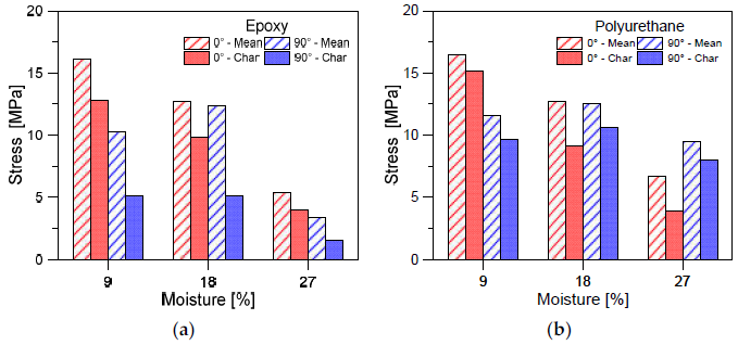
The estimated results are shown in Figure 8, in terms of stress peak at failure for each set of specimens (under the assumption of uniform stress distribution for the bond-line as a whole). Mean and characteristic values of ultimate stress are grouped by adhesive type and rod arrangement, as a function of the service class/moisture content.
As expected from Table 3 and Table 4, a major scatter of mean and characteristic values was observed especially for the epoxy-bonded rods, rather than polyurethane samples. Besides, the global decrease of stress peak can be observed, both in mean and characteristic parameters, as far as the moisture level increases. This is a further confirmation of sensitivity of different adhesive types to operational conditions.
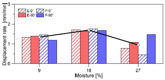
In this regard, it is worth mentioning that the imposed displacement rate (in the range of 0.5–2.0 mm/min), as previously discussed, was adapted test by test. The postprocessing stage of experimental measurements was quantified in average rate values that are summarized in Figure 9, as obtained for each series of specimens. Worth noting are the lower rate values for epoxy or polyurethane specimens under high moisture (27%) and bonding parallel to the grain. This was required by the pronounced viscous response of adhesives used.
4. Discussion of Experimental Observations
4.1. Service Class and Adhesive Behaviour
Undoubtedly, the experimental investigations revealed significant differences of the mechanical behaviour of bonded-in rod connections with different adhesives when exposed to wet climate. The test set-up and the support of the DIC system helped in obtaining empirical results of practical use. Rheological behaviour indicates that, in terms of reliability, special attention should be paid to the joints exposed to the extreme climatic conditions. Additional requirements in standards should be included or certification from the adhesive manufacturer should be sought to ensure the safe use of this type of joints.
Tests indicated a significant effect of moisture content on the adhesive stickiness. While only small changes were observed for service class 2, for service class 3 the adhesive stickiness began to recede dramatically. For epoxy specimens, the entire adhesive matrix started to slip smoothly, what is especially characteristic for rods bonded perpendicular to the grains, while on the rods bonded parallel, any pieces of wood grains on the adhesive matrix is not visible. This is indicating that bearing capacity of the joint is defined by shear strength of the interface on exact line between the adhesive matrix and the wood. Polyurethane specimens showed enhanced behaviour, especially for rods bonded perpendicular to the grains. The reason for such behaviour can be justified in higher chemical properties of the new generation of this type of adhesives, which is recommended for use in moist environments. Indicatively, it can be stated that the use of epoxy adhesives is not recommended for service class 3, while polyurethane adhesives can be still used, but with careful consideration for the technical characteristics given by the manufacturer.
4.2. Service Type and Slip Modulus
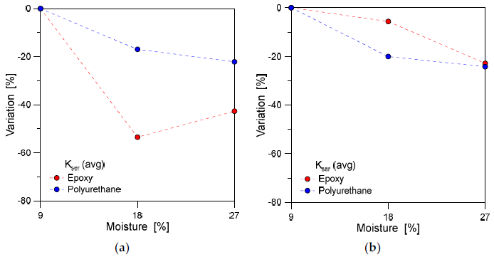
In Figure 10, the average % variation of slip modulus Kser is shown as a function of the moisture content, the bonding direction to the grain and the type of adhesive.
The service class, as shown, generally resulted in severe modification of mechanical parameters for the tested specimens, both for epoxy or polyurethane bonded rods, with more pronounced effects for loading parallel to the grain (Figure 10a). In the perpendicular direction, a rather stable variation of average stiffness results can be observed in Figure 10b for both the adhesive types.
4.3. Service Class and Load-Bearing Capacity
The above quantitative comparisons were further supported by the qualitative analysis of experimental outcomes. In general terms, the analysis of BiR performances under different service conditions can be summarized as follows.
For service class 1:
- test results confirmed the assumption of similar load-bearing capacity for both the epoxy and the polyurethane adhesive types;
- specimens with polyurethane showed mild bilinear behaviour and 10% higher capacity then specimens with epoxy, which proved to offer a pure linear behaviour with brittle fracture.
For service class 2:
- specimens showed a ≈20% drop in the measured average load capacity;
- the load-bearing behaviour and failure modes were found to closely agree with the experimental observations of specimens in service class 1.
Finally, for service class 3:
- specimens showed large drop of load-bearing capacity. A huge drop was found especially for epoxy bonded specimens, where failure happened on −50% of maximum average force of corresponding specimens in service class 1;
- in any case, the failure modes were still observed in agreement with the previous specimens.
In this regard, the analysis of test results can take advantage of existing empirical formulations that have been proposed for glued-in-rods with parallel or perpendicular rod-to-grain orientation. Among the literature efforts for the analytical analysis and design of BiR connections, the failure load of parallel rod-to-grain arrangement can be for example estimated as [15]:
The empirical equation has been proposed by Feligioni et al. [15] to predict the pull-out strength at failure (in N), where L is the joint length (mm); fv is the shear strength of wood (MPa); d is the rod diameter (mm); dequ the smaller between the hole diameter dh and the rod diameter d multiplied by 1.25 (mm); e is the joint thickness (mm); k is a parameter proposed in 0.086 or 1.213 (based on experimental fitting), for adhesives with brittle or ductile behaviour respectively.
For comparative studies with the current experimental results, the above parameters are set:
with ρ = 600 kg/m3 the average density of wood specimens (±25); e = 2 mm, L = 60 mm.
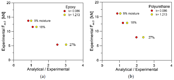
From Equation (6), the comparative analysis is carried out towards the average (mean) experimental failure loads earlier discussed, for various configurations of specimens. The findings are summarized in Figure 11, as a function of the analytical vs. experimental failure load, the adhesive type and the moisture/service class. As far as the service class 1 is taken into account, it is possible to see that the analytical to experimental ratio is in the order of the unit. This suggests a certain correlation of literature model with the current experiments. Besides, the analysis of higher moisture content tends to progressively overestimate the analytical failure force for the examined specimens, as shown in Figure 11 for both the adhesive types. Furthermore, the high moisture content reveals also pronounced effects due to the input k coefficients calibrated from [15].
For specimens with perpendicular rod-to-glue arrangement, the analytical model proposed by Yeboah et al. is considered [30]. The model, in particular, assumes that the load-bearing capacity is given by:
with the limit applicability condition of L < 15dh.
The empirical model of Equation (9) agrees with the experimental trends earlier discussed in Figure 8. As far as the moisture content increases and the adhesive degradation of mechanical properties increases, Equation (9) itself severely overestimates the expected axial force at failure for the tested joints. In Figure 12, the empirical derivation of material strength is shown for epoxy or polyurethane specimens, as obtained from the mean experimental results.
5. LEFM-Based Analytical Model
5.1. State-of-Art
Theoretical approaches, based on the stress distribution in the joint, have been used to describe the laws governing the mechanical behaviour of connections by glued-in rods. One of the pioneering works was by Volkersen [31], who developed an elastic analysis of the shear distribution in a single lap joint. However, the substrates were assumed to respond to the load only in tension and the adhesive to respond only in shear. A further development was made by Goland and Reissner [32], who included the influence of a bending moment in the connection in their calculation model. Later, Hart-Smith [33] introduced elastic-plastic stress distribution of anisotropic materials in the analysis. Depending on the ductility of the bond-line, these traditional strength analyses will be more or less accurate.
More recently, the behaviour of glued-in rods was investigated within the framework of fracture mechanics. In this approach, a pre-existing crack in the joint is assumed to lead to a stress singularity so that the traditional maximum stress criterion can be no longer applied. For instance, in accordance with LEFM, Serrano [11] proposed an evaluation model of the load bearing capacity for a single glued-in rod, assuming that failure of the joint could occur when the energy release rate is equal to the fracture energy. In the same year, Gustafsson [17] took into consideration the damage amount preceding the failure of a joint through an approach based on nonlinear fracture mechanics (NLFM), and essentially based on the mode II fracture energy. Thus, many empirical or theoretical design calculations could be found in literature to estimate either the shear strength (especially in studies based on elastic stress analysis) or the fracture energy in mode II. It should be noted that most existing studies were either based on experiments or numerical investigations, but rarely combined both approaches [21].
5.2. Model Definition
In order to check this assumption, the study of the fracture behaviour of BiR connection is proposed within the framework of equivalent LEFM, which is well known to be useful to characterize the quasibrittle failure of load-bearing components [21].
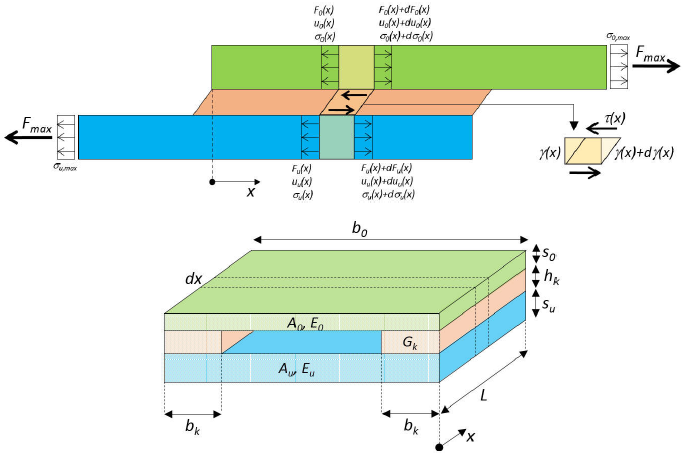
The reference mechanical model is schematized in Figure 13, with evidence of the required geometrical and mechanical parameters in the detailed view.
Considering that the joint acts as a fibre in the matrix, where the fibre represents a steel glued-in bar and the matrix consists of the wood log as in Figure 13, the following model of shear stresses distribution along the joint is proposed in this study:
where A0 is cross-area of the wooden part; bk is the mean width of the adhesive layer; σ0,max represents the maximum normal stress in the BiR; x is the length coordinate; L denotes the length of the adhesive joint (anchorage length); ω is a correction factor that can be estimated from:
and:
By integrating Equation (10) to get a strain energy release rate, the J-integral method could be implemented directly. Further, the problem analysis and the definition of an accurate behaviour model for BiR connections should be necessarily based on local stress distribution which has been obtained in the framework of DIC system (i.e., Figure 7).
According to the known maximum shear strength of wood, it is possible to predict the bearing capacity of the BiR connection, i.e., maximum pull-out force, as:
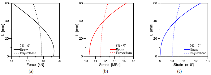
From the developed analytical model, the variation of the shear force, stress and strain in BiR connections can be thus predicted along the bonding length L. Selected examples are proposed in Figure 14.
5.3. Assessment of Analytical Predictions
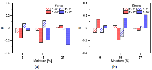
The proposed analytical model is further assessed by taking advantage of the available test results and of nominal material properties earlier discussed. Parametric calculations were carried out on the grouped specimens (average estimates) in terms of shear force and stress, by changing the adhesive type, arrangement and environment condition.
In this regard, the analytical model proved to offer reliable estimates for both the parameters of force and stress agreeing with the general trends of Figure 14. Comparative examples are proposed in Figure 15, in terms of force or stress, as obtained for grouped specimens as a function of their service class. It should be noted that the error ratio R is found both to overestimate or underestimate the expected parameter, for all the types of BiR specimens. Most importantly, however, is that the collected R values confirm the rather small scatter for all the analytical predictions, thus confirming the validity and accuracy of the approach.
6. Conclusions
In this paper, the mechanical performance of bonded-in rod (BiR) connections for structural timber applications has been explored experimentally and analytically.
The experimental investigations revealed, significant differences in the observed mechanical behaviour of BiR connections, by changing the adhesives type, the bonding arrangement and the wet climate exposure. The pull-out test set-up and the use of a digital image correlation (DIC) system, in particular, helped to obtain results in support of the definition of generalized design tools for this type of connections.
The experimental study, in most of the cases, exhibited a failure mechanism of the connections in the wood, in the vicinity of the wood–adhesive interface. As such, a study of the stress field along this interface was performed with the use of a newly developed linear elastic fracture mechanics (LEFM) formulation. In addition to the shear stress, expected for this kind of connection, the stress field analysis revealed the existence of normal stress (to the interface), which was relevant at the onset of the failure.
The observed rheological behaviour of adhesive types in use further indicates that (in terms of reliability) special attention should be paid to joints exposed to extreme climatic conditions. The current study provided useful information about the short-term behaviour of bonded-in-rods. However, the long-term behavioural analysis of BiR connections requires further investigations, in order to check the mechanical performance of this repair process according to service classes defined in the European timber design codes. Most importantly, additional requirements in standards should be included, or certification from the adhesive manufacturer should be sought, to ensure the safe use of this type of joints in practical applications. In this regard, further research efforts will be dedicated to the in-depth analysis of mechanical parameters and their sensitivity to severe environment conditions, so as to include additional configurations and parameters of technical interest.
Author Contributions
This research paper results from a joint collaboration of the involved authors. More precisely J.B. and M.K.B. carried out the experiments; C.B. and V.R. contributed to the post-processing of results; V.R. supervised all the research activities. All authors have read and agreed to the published version of the manuscript.
Funding
The EU-COST Action CA18120 is gratefully acknowledged for providing financial support to the first and third authors (J.B. visitor at Aarhus University, Denmark and C.B. visitor at University of Zagreb, Croatia), in the framework of CERTBOND Short Term Scientific Missions—STSM grants.
Institutional Review Board Statement
Not applicable.
Informed Consent Statement
Not applicable.
Data Availability Statement
Data supporting this research study will be made available upon request.
Acknowledgments
This publication is based upon work from EU-COST Action CA18120 (CERTBOND—https://certbond.eu/ (accessed on 16 February 2021)), supported by COST (European Cooperation in Science and Technology—https://www.cost.eu/ (accessed on 16 February 2021)). MDPI is also acknowledged for waived APCs (C.B.).
Conflicts of Interest
The authors declare no conflict of interest.
Appendix A
Experimental force–displacement curves for the investigated BiR specimens, grouped by adhesive type, rod-to-glue arrangement and service class.
Figure A1.
Experimental force–displacement results for specimens with (a) epoxy or (b) polyurethane glue, under 18% moisture and parallel rod-to-grain arrangement.
Figure A1.
Experimental force–displacement results for specimens with (a) epoxy or (b) polyurethane glue, under 18% moisture and parallel rod-to-grain arrangement.

Figure A2.
Experimental force–displacement results for specimens with (a) epoxy or (b) polyurethane glue, under 18% moisture and bonding and perpendicular rod-to-grain arrangement.
Figure A2.
Experimental force–displacement results for specimens with (a) epoxy or (b) polyurethane glue, under 18% moisture and bonding and perpendicular rod-to-grain arrangement.

Figure A3.
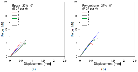
Experimental force–displacement results for specimens with (a) epoxy or (b) polyurethane glue, under 27% moisture and bonding and parallel rod-to-grain arrangement.
Figure A3.
Experimental force–displacement results for specimens with (a) epoxy or (b) polyurethane glue, under 27% moisture and bonding and parallel rod-to-grain arrangement.

Figure A4.
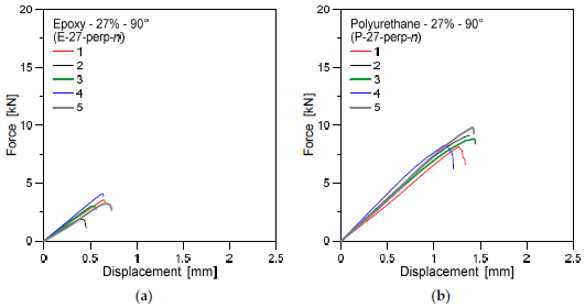
Experimental force–displacement results for specimens with (a) epoxy or (b) polyurethane glue, under 27% moisture and bonding and perpendicular rod-to-grain arrangement.
Figure A4.
Experimental force–displacement results for specimens with (a) epoxy or (b) polyurethane glue, under 27% moisture and bonding and perpendicular rod-to-grain arrangement.

References
- Tlustochowicz, G.; Serrano, E.; Steiger, R. State-of-the-art review on timber connections with glued-in steel rods. Mater. Struct. 2010, 44, 997–1020. [Google Scholar] [CrossRef]
- Serrano, E.; Gustafsson, P.J. Fracture mechanics in timber engineering—strength analyses of components and joints. Mater. Struct. 2007, 40, 87–96. [Google Scholar] [CrossRef]
- Batchelar, M.; Fragiacomo, M. Timber frame moment joints with Glued-in Steel Rods I: Design. J. Struct. Eng. 2012, 138, 789–801. [Google Scholar]
- Otero Chans, D.; Estévez Cimadevila, J.; Martín-Gutiérrez, E.; Vazquez, J.A. Failure modes in double-sided pull-out test of threaded steel rods glued-in hardwood. In Proceedings of the World Conference of Timber Engineering, Trentino, Italy, 20–24 June 2010. [Google Scholar]
- Stepinac, M.; Rajcic, V.; Koscak, J.; Damjanovic, D. Assessment of the pull-out strength of glued-in rods with different test methods. In Proceedings of the World Conference on Timber Engineering, Vienna, Austria, 22–25 August 2016. [Google Scholar]
- Steiger, R.; Serrano, E.; Stepinac, M.; Rajčić, V.; O’Neill, C.; McPolin, D.; Widmann, R. Strengthening of timber structures with glued-in rods. Constr. Build. Mater. 2015, 97, 90–105. [Google Scholar] [CrossRef] [Green Version]
- Broughton, J.; Hutchinson, A. Pull-out behaviour of steel rods bonded into timber. Mater. Struct. 2001, 34, 100–109. [Google Scholar] [CrossRef]
- Gattesco, N.; Gubana, A.; Buttazzi, M.; Melotto, M. Experimental investigation on the behavior of glued-in rod joints in timber beams subjected to monotonic and cyclic loading. Eng. Struct. 2017, 147, 372–384. [Google Scholar] [CrossRef]
- Rajcic, V.; Bjelanovic, A.; Rak, M. Comparison of the Pull-out Strength of Steel Bars Glued in GluLam Elements Obtained Experimentally and Numerically. In Proceedings of the International Council for Research and Innovation in Building and Construction “Working Commission W 18—Timber Structures” Meeting Thirty Nine/Goerlacher, Rainer (ur.), Florence, Italy, 28–31 August 2006. [Google Scholar]
- Stepinac, M.; Rajcic, V.; Hunger, F.; van de Kuilen, J.W.G. Glued-in rods in beech laminated veneer lumber. Eur. J. Wood Wood Prod. 2016, 74, 463–466. [Google Scholar] [CrossRef]
- Serrano, E. Glued-in rods for timber structures—A 3D model and finite element parameter studies. Int. J. Adhes. Adhes. 2000, 21, 115–127. [Google Scholar] [CrossRef]
- Bedon, C.; Fragiacomo, M. Numerical analysis of timber-to-timber joints and composite beams with inclined self-tapping screws. Compos. Struct. 2019, 207, 13–28. [Google Scholar] [CrossRef]
- Xu, B.; Bouchair, A.; Racher, P. Analytical study and finite element modelling of timber connections with glued-in rods in bending. Constr. Build. Mater. 2012, 34, 337–345. [Google Scholar] [CrossRef]
- Skec, L.; Bjelanovic, A.; Jeleni, G. Glued timber-concrete beams—Analytical and numerical models for assessment of composite action. Eng. Rev. 2013, 33, 41–49. [Google Scholar]
- Feligioni, L.; Lavisci, P.; Duchanois, G.; De Ciechi, M.; Spinelli, P. Influence of glue rheology and joint thickness. Holz als Roh-und Werkstoff 2003, 61, 281–287. [Google Scholar]
- Stepinac, M.; Hunger, F.; Tomasi, R.; Serrano, E.; Rajcic, V.; Van de Kuilen, J.W.G. Comparison of design rules for glued-in rods and design rule proposal for implementation in European standards. In Proceedings of the CIB-W18 Timber Structures, Meeting 46, Vancouver, BC, Canada, 26–29 August 2013. [Google Scholar]
- Gustafsson, P.J.; Serrano, E. Predicting the pull-out strength of glued-in rods. In Proceedings of the Sixth World Conference on Timber Engineering, Whistler Resort, BC, Canada, 31 July–3 August 2000; Volume 1. [Google Scholar]
- Aicher, S.; Dill-Langer, G. Influence of moisture, temperature and load duration on performance of glued-in rods. In Stuttgart, Rilem Symposium 2001—Joints in Timber Structures; Springer—International Publisher Science: Berlin, Germany, 2001. [Google Scholar]
- Verdet, M.; Coureau, J.-L.; Cointe, A.; Salenikovich, A.; Galimard, P.; Delisée, C.; Toro, W.M. Creep performance of glued-in rod joints in controlled and variable climate conditions. Int. J. Adhes. Adhes. 2017, 75, 47–56. [Google Scholar] [CrossRef]
- Verdet, M.; Salenikovich, A.; Cointe, A.; Coureau, J.-L.; Galimard, P.; Munoz Toro, W.; Blanchet, P.; Delisee, C. Mechanical performance of polyurethane and epoxy adhesives in connections with glued-in rods at elevated temperatures. BioResources 2016, 11, 8200–8214. [Google Scholar] [CrossRef] [Green Version]
- Lartigau, J.; Coureau, J.-L.; Morel, S.; Galimard, P.; Maurin, E. Mixed mode fracture of glued-in rods in timber structures. Int. J. Fract. 2015, 1992, 71–86. [Google Scholar] [CrossRef]
- Taupin, J. Restauration à la résine époxyde de planchers et charpentes au Monastère de la Grande Chartreuse. Bull. D’informations Tech. 1980, 92, 34–43. [Google Scholar]
- CEN: Timber Structures—Test Methods—Determination of Embedment Strength and Foundation Values for Dowel Type Fasteners (EN 383:2007); European Committee for Standardization: Brussels, Belgium, 2007.
- CEN: Adhesives, Phenolic and Aminoplastic, for Load-Bearing Timber Structures—Classification and Performance Requirements (EN 301:2017); European Committee for Standardization: Brussels, Belgium, 2017.
- CEN/TC 250 SC 5: Glued-in Rods in Glued Structural Timber Products—Testing, Requirements and Bond Shear Strength Classification (prEN 17334); European Committee for Standardization: Brussels, Belgium, 2018.
- EN 1995-1. Eurocode 5: Design of Timber Structures. Part 1-1: General Common Rules and Rules for Buildings; European Committee for Standardization: Brussels, Belgium, 2005.
- Bergstedt, A.; Lyck, C. Larch Wood—A Literature Review; Forest & Landscape Working Papers no. 23; Forest & Landscape Denmark: Hørsholm, Denmark, 2007. [Google Scholar]
- EN 15274. General Purpose Adhesives for Structural Assembly—Requirements and Test Methods; European Committee for Standardization: Brussels, Belgium, 2015.
- EN1382. Timber Structures—Test Methods—Withdrawal Capacity of Timber Fasteners; European Committee for Standardization: Brussels, Belgium, 2016.
- Yeboah, D.; Taylor, S.; McPolin, D.; Gilfillan, J.; Gilbert, S. Behaviour of joints with bonded-in steel bars loaded parallel to the grain of timber elements. Constr. Build Mate. R 2011, 25, 2312–2317. [Google Scholar] [CrossRef]
- Volkersen, O. Die niektraftverteilung in zugbeanspruchten mit konstanten laschenquerschritten. Luftfahrtforschung 1938, 15, 41–47. [Google Scholar]
- Goland, M.; Reissner, E.J. The stresses in cemented joints. Appl. Mech. 1944, 66, A17–A27. [Google Scholar] [CrossRef]
- Hart-Smith, L.J. Adhesive-Bonded Double-Lap Joints; Nasa CR-112235: Long Beach, CA, USA, 1973. [Google Scholar]
Figure 1.
Preparation of bonded-in rod (BiR) connections with M10 steel rod (examples of polyurethane adhesive bonding): (a) half-size and (b) full-size specimens.
Figure 1.
Preparation of bonded-in rod (BiR) connections with M10 steel rod (examples of polyurethane adhesive bonding): (a) half-size and (b) full-size specimens.

Figure 2.
Preparation of specimens under controlled atmosphere.

Figure 3.
Pull-out test set-up: schematic view and details (nominal dimension in mm).

Figure 4.
Experimental force–displacement results for specimens with (a) epoxy or (b) polyurethane glue, under 9% moisture and parallel rod-to-grain arrangement.
Figure 4.
Experimental force–displacement results for specimens with (a) epoxy or (b) polyurethane glue, under 9% moisture and parallel rod-to-grain arrangement.

Figure 5.
Experimental force–displacement results for specimens with (a) epoxy or (b) polyurethane glue, under 9% moisture and perpendicular rod-to-grain arrangement.
Figure 5.
Experimental force–displacement results for specimens with (a) epoxy or (b) polyurethane glue, under 9% moisture and perpendicular rod-to-grain arrangement.

Figure 6.
Example of failure configuration for the tested samples: (a) epoxy and (b) polyurethane bonded rods for half-size specimens (18% moisture, parallel rod-to-grain arrangement) and (c) full-size specimens.
Figure 6.
Example of failure configuration for the tested samples: (a) epoxy and (b) polyurethane bonded rods for half-size specimens (18% moisture, parallel rod-to-grain arrangement) and (c) full-size specimens.

Figure 7.
Example of the typical shear strain distribution along the rod, as obtained by digital image correlation (DIC).
Figure 7.
Example of the typical shear strain distribution along the rod, as obtained by digital image correlation (DIC).

Figure 8.
Stress peak at failure, as observed for (a) epoxy or (b) polyurethane bonded rods in various arrangements. Comparison of mean and characteristic experimental results.
Figure 8.
Stress peak at failure, as observed for (a) epoxy or (b) polyurethane bonded rods in various arrangements. Comparison of mean and characteristic experimental results.

Figure 9.
Average experimental displacement rate for the investigated series of specimens.

Figure 10.
Average experimental variation of slip modulus Kser for specimens with (a) parallel or (b) perpendicular rod-to-grain arrangement.
Figure 10.
Average experimental variation of slip modulus Kser for specimens with (a) parallel or (b) perpendicular rod-to-grain arrangement.

Figure 11.
Average experimental failure load versus the ratio of analytical prediction, as obtained for specimens with (a) epoxy or (b) polyurethane adhesive and parallel rod-to-grain arrangement.
Figure 11.
Average experimental failure load versus the ratio of analytical prediction, as obtained for specimens with (a) epoxy or (b) polyurethane adhesive and parallel rod-to-grain arrangement.

Figure 12.
Inverse experimental derivation of fv,90,mean strength, based on Equation (9), for epoxy or polyurethane specimens with perpendicular rod-to-glue arrangement.
Figure 12.
Inverse experimental derivation of fv,90,mean strength, based on Equation (9), for epoxy or polyurethane specimens with perpendicular rod-to-glue arrangement.

Figure 13.
Mechanical model for the analysis of force transmission and deformation behaviour in BiR connections.
Figure 13.
Mechanical model for the analysis of force transmission and deformation behaviour in BiR connections.

Figure 14.
Analytical prediction of shear (a) force, (b) stress and (c) strain in BiR connections with epoxy or polyurethane adhesives (examples for 9% moisture and parallel rod-to-glue arrangement).
Figure 14.
Analytical prediction of shear (a) force, (b) stress and (c) strain in BiR connections with epoxy or polyurethane adhesives (examples for 9% moisture and parallel rod-to-glue arrangement).

Figure 15.
Average experimental failure load versus the ratio of analytical prediction, as obtained for specimens with (a) epoxy or (b) polyurethane adhesive and parallel rod-to-grain arrangement.
Figure 15.
Average experimental failure load versus the ratio of analytical prediction, as obtained for specimens with (a) epoxy or (b) polyurethane adhesive and parallel rod-to-grain arrangement.


Table 1.
Service classes for timber structures and typical examples.
| Service Class | |||
|---|---|---|---|
| 1 | 2 | 3 | |
| Climatic condition | 20 °C, relative humidity >65% for few weeks/year | 20 °C, relative humidity <85% except for few weeks/year | Climatic conditions worse than class 2 |
| Average moisture content in timber | about 12% | always <18% | >18% |
| Examples | Interiors; warmed and conditioned environments, with limited hygrothermal variations | Covered exteriors; unconditioned environments (shelters, cold roofs, terraces) or humid ones (swimming pools); beam ends on interior walls, well ventilated and drained | Exteriors; bridges, columns, piles; beam ends on exterior walls, also for heated environments |
Table 2.
Nominal mechanical properties for KGK EPOCON ‘88 (two-component epoxy), LOCTITE PUREBOND CR 821 (two-component polyurethane) and Siberian larch wood (Larix sibirica).
Table 2.
Nominal mechanical properties for KGK EPOCON ‘88 (two-component epoxy), LOCTITE PUREBOND CR 821 (two-component polyurethane) and Siberian larch wood (Larix sibirica).
| KGK EPOCON ‘88 | LOCTITE PUREBOND CR 821 | Wood | ||
|---|---|---|---|---|
| Compressive strength | (MPa) | 91.5 | 79.9 | 61.5 |
| Tensile strength | (MPa) | 32.5 | 27.5 | 120.5 |
| Bending strength | (MPa) | 60.9 | - | 97.8 |
| Modulus of elasticity | (MPa) | 29.5 | 29.5 | 8.5 |
Table 3.
Maximum axial force, displacement and slip modulus for specimens with parallel rod-to-grain arrangement (mean experimental values).
Table 3.
Maximum axial force, displacement and slip modulus for specimens with parallel rod-to-grain arrangement (mean experimental values).
| Bond | |||||||
|---|---|---|---|---|---|---|---|
| Two-Component Epoxy | Two-Component Polyurethane | ||||||
| Moisture | Parameter | Avg. | CoV. [%] | St.Dev. | Avg. | CoV. [%] | St.Dev. |
| 9% | Fax [kN] | 15.216 | 9.1 | 1.390 | 15.545 | 3.3 | 0.519 |
| dmax [mm] | 1.222 | 20.3 | 0.248 | 1.362 | 11.4 | 0.155 | |
| Kser [N/mm] | 14,548.086 | 10.5 | 1528.301 | 12,475.290 | 9.6 | 1197.480 | |
| 18% | Fax [kN] | 12.015 | 10.8 | 1.301 | 11.987 | 13.1 | 1.575 |
| dmax [mm] | 1.233 | 6.4 | 0.079 | 1.227 | 27.1 | 0.333 | |
| Kser [N/mm] | 6769.256 | 28.7 | 1942.825 | 10,362.893 | 15.6 | 1613.003 | |
| 27% | Fax [kN] | 5.117 | 11.5 | 0.591 | 6.294 | 20.6 | 1.293 |
| dmax [mm] | 0.607 | 17.1 | 0.104 | 0.625 | 20.9 | 0.131 | |
| Kser [N/mm] | 8341.809 | 22.1 | 1843.689 | 10,728.730 | 4.1 | 441.031 | |
Table 4.
Maximum axial force, displacement and slip modulus for specimens with perpendicular rod-to-grain arrangement (mean experimental values).
Table 4.
Maximum axial force, displacement and slip modulus for specimens with perpendicular rod-to-grain arrangement (mean experimental values).
| Bond | |||||||
|---|---|---|---|---|---|---|---|
| Two-Component Epoxy | Two-Component Polyurethane | ||||||
| Moisture | Parameter | Avg. | CoV. [%] | St.Dev. | Avg. | CoV. [%] | St.Dev. |
| 9% | Fax [kN] | 9.722 | 25.7 | 2.501 | 10.908 | 7.0 | 0.760 |
| dmax [mm] | 1.352 | 26.9 | 0.364 | 1.325 | 4.8 | 0.064 | |
| Kser [N/mm] | 7360.208 | 36.3 | 2668.764 | 9869.502 | 17.0 | 1674.434 | |
| 18% | Fax [kN] | 11.687 | 3.5 | 0.408 | 11.801 | 6.7 | 0.792 |
| dmax [mm] | 1.944 | 12.9 | 0.251 | 1.824 | 10.6 | 0.193 | |
| Kser [N/mm] | 6943.509 | 15.9 | 1105.534 | 7887.684 | 3.6 | 282.079 | |
| 27% | Fax [kN] | 3.149 | 25.8 | 0.814 | 8.914 | 6.6 | 0.587 |
| dmax [mm] | 0.573 | 19.4 | 0.111 | 1.330 | 9.3 | 0.124 | |
| Kser [N/mm] | 5675.074 | 13.9 | 788.096 | 7476.200 | 6.1 | 456.498 | |
Publisher’s Note: MDPI stays neutral with regard to jurisdictional claims in published maps and institutional affiliations. |
© 2021 by the authors. Licensee MDPI, Basel, Switzerland. This article is an open access article distributed under the terms and conditions of the Creative Commons Attribution (CC BY) license (http://creativecommons.org/licenses/by/4.0/).
Share and Cite
MDPI and ACS Style
Barbalić, J.; Rajčić, V.; Bedon, C.; Budzik, M.K. Short-Term Analysis of Adhesive Types and Bonding Mistakes on Bonded-in-Rod (BiR) Connections for Timber Structures. Appl. Sci. 2021, 11, 2665. https://doi.org/10.3390/app11062665
AMA Style
Barbalić J, Rajčić V, Bedon C, Budzik MK. Short-Term Analysis of Adhesive Types and Bonding Mistakes on Bonded-in-Rod (BiR) Connections for Timber Structures. Applied Sciences. 2021; 11(6):2665. https://doi.org/10.3390/app11062665
Chicago/Turabian StyleBarbalić, Jure, Vlatka Rajčić, Chiara Bedon, and Michal K. Budzik. 2021. "Short-Term Analysis of Adhesive Types and Bonding Mistakes on Bonded-in-Rod (BiR) Connections for Timber Structures" Applied Sciences 11, no. 6: 2665. https://doi.org/10.3390/app11062665
Note that from the first issue of 2016, this journal uses article numbers instead of page numbers. See further details here.