1. Introduction
Stealth platforms have low radar cross section (RCS), but their radar signature increases significantly when antennas are mounted on them for communication purposes [
1,
2]. This can compromise their ability to counter the radar waves, so, in this regard, design and development of low RCS antennas is deemed necessary, for safety and security.
Reduction of the antenna’s RCS is a critical feat, and several methods have been investigated to ensure that the antenna radiation properties are least affected while attempting to reduce its RCS. One of the methods is structural/geometrical shaping [
3,
4,
5,
6,
7], in which the shape of the radiating structure is modified to ensure the backscatter avoids the threat direction. The other method is based on periodic structures, and this includes the use of radar absorbing materials (RAMs) [
8,
9,
10], frequency selective surface (FSS) ground plane [
11,
12], FSS radome [
13,
14], electromagnetic bandgap (EBG) structures [
15,
16,
17], artificial magnetic conductors (AMCs) [
18], perfect metamaterial absorbers (MAs) [
19,
20,
21,
22], and polarization conversion metasurfaces (PCMs) [
23,
24]. In all of the above configurations, the periodic structure is implemented either at the ground plane, on top of the radiator, or loaded around the planar radiator, and, in all of these implementations, although the RCS is lowered, the antenna radiation property either remains just intact, or it slightly deteriorates.
To improve the antenna radiation properties in parallel with lowering the RCS, further research has led to using partially reflecting surfaces (PRSs) in a Fabry–Perot Cavity (FPC) configuration, as evident in [
25,
26,
27,
28]. In all of these works, backscatter reduction was achieved, and broadside antenna gain was enhanced. To achieve this, mainly an absorptive FSS (AFSS) (periodic loop elements with lumped resistors) surface was used with a uniform PRS—a PRS employing identical unit cell elements in a grid, and hence identical transmission/reflection responses over the entire surface of the superstrate. With reference to antenna, in transmission mode, the uniform superstrate acts as a PRS for broadside gain enhancement, and in receiving mode, it acts as an electromagnetic (EM) absorber for normal EM wave illumination over a wide frequency range.
Some interesting work can evolve if a PRS that has a phase gradient can be used with an AFSS after appropriate design adjustments. Our aim in this work is to develop a superstrate structure that consists of phase gradient metasurface (PGM) conjoined with an AFSS, such that not only the wideband monostatic RCS reduction and peak gain enhancement can be achieved for a patch antenna, but also the peak radiation can be steered in a fixed angle, which becomes an additional antenna functionality in comparison to the works done previously. In addition, the design goal also includes the realization of a reduced cavity profile. In [
29], the use of PGM can be found, integrated with an AFSS. Its primary purpose there is to scatter away the in-band incident wave; however, the presence of an absorptive surface may only serve the same to an appropriate level, by suppressing the in-band incident wave. The peak radiation direction is still towards broadside.
This study investigates the use of a PRS constructed with unit cells that have phase shifts implemented by a dimensional gradient, and henceforth progressively varying transmission/reflection properties over the surface of the superstrate. The designed PRS is a composite structure, meaning thereby it utilizes both sides of the dielectric, and this feature aids in reducing the cavity height to λ/4. The absorptive surface consists of periodic loop elements loaded with lumped resistors, and it works in conjunction with the composite PRS that is formed by gradated mesh (inductive) structure on one side and constant patch (capacitive) elements on the other side. The excitation source of the cavity is a patch radiator designed at 6 GHz (C-band). Simulations have been validated with a fabricated prototype. Off-broadside peak gain of 9.4 dB was achieved at −38° offset in the elevation plane, along the axis of the gradient. The wideband (in-band + out-of-band) monostatic RCS reduction was achieved over a frequency range of 4–16 GHz (120%), with average RCS reduction exceeding 8.5 dB for the two orthogonal (x/y) polarizations.
The low scattering property of the proposed antenna makes it suitable to be integrated with stealth type platforms. That is because the platform’s low observability would still remain low despite mounting the antenna onto it for communication, and this paves the way for its multiple applications in the military and defense realm. One example is a side looking air borne radar (SLAR) [
30], where the antenna points to a sideward direction and requires physical tilting of its structure. The proposed antenna can potentially be used in this scenario. Similarly, for the aerial security, surveillance, and reconnaissance applications, it can be used on unmanned aerial vehicles (UAVs) and drones where downward pointing high gain beam is more pragmatic for communication with the ground targets [
31]. The development of low RCS multiple-input multiple-output (MIMO) antennas is also becoming popular due to their technological advantages, and as such, the proposed technique can be further developed to realize pattern decorrelated low observable MIMO antennas [
32,
33]. In addition, the antenna can be utilized for any military communication application where fix tilt-angled communication is required [
34].
2. Unit Cell Design and Proposed FPC Antenna
The goal is to design a stacked combination of layers of FSS elements, in a unit cell configuration, which when paced as a grid above the patch antenna (excitation source) in an FPC configuration, should realize the following four functionalities/objectives in parallel:
Wideband monostatic RCS reduction.
Appropriate gain enhancement.
Off-broadside peak radiation.
Reduced cavity height (λ/4).
Where λ is free space wavelength at operating frequency. Conventionally, the FP cavity, with an excitation source within, resonates when a PRS is placed at a height of ~λ/2 above the ground plane reflector, and results in an enhanced gain radiation of the source antenna. The cavity height (h) at wavelength (λ) corresponding to the operating frequency can be calculated as [
35]:
where φ
PRS is the phase of reflection coefficient of PRS, φ
G is reflection phase of ground reflector, and N defines the resonance order. φ
G is further estimated as:
where Z
d and Z
0 are characteristic impedances of the dielectric and air, respectively, β represents the dielectric phase constant (given as 2π/λ), and d is the dielectric thickness over which the ground plane is lying. For the metallic reflector only (i.e., without the dielectric), the reflection phase is π. For N = 0, the resonant cavity height turns out to be λ/2 if φ
PRS is assumed to be of π rad. If a PRS can be designed to exhibit a 0 reflection phase, the cavity height can be reduced to λ/4.
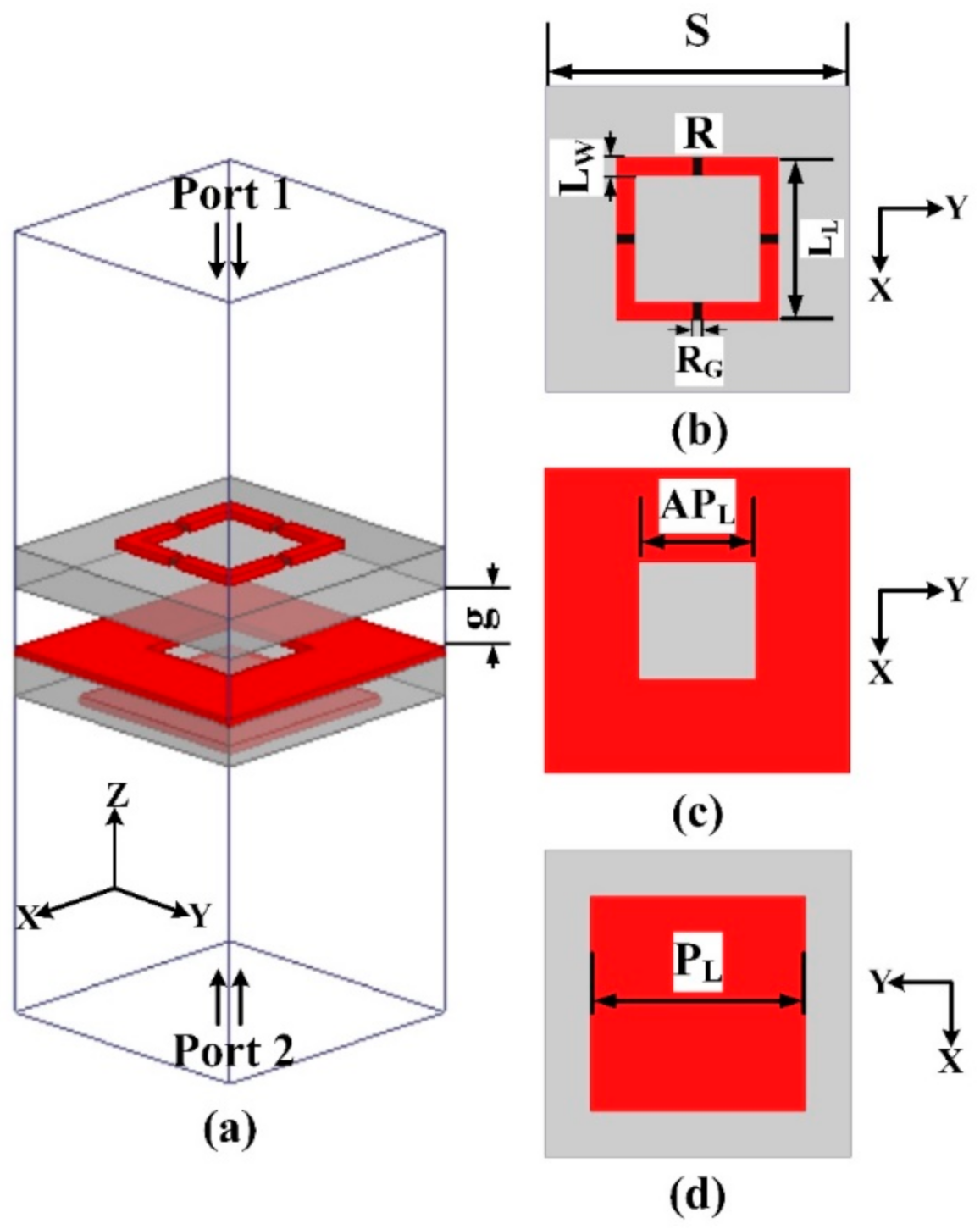
The unit cell with port designations is shown in
Figure 1a. To obtain wideband RCS reduction, the top surface of the unit cell, as shown in
Figure 1b, was constructed from a closed metallic ring of square shape, with four RF resistors (100 Ω each) soldered on four sides. Such a resistive periodic surface (AFSS) mounted on a perfect electric conductor (PEC) plane with a dielectric sandwiched in-between serves as a wideband RAM for an impinging electromagnetic (EM) wave [
36]. However, for the proposed objectives, the backing PEC plane has to be replaced with an appropriate PRS, so that all our four objectives can be simultaneously achieved. A survey of literature [
37,
38,
39] shows various designs of reflective surfaces; however, the appropriate PRS to be conjoined with the selected AFSS should be:
Symmetric in design, so that wideband RCS reduction can be achieved for both polarizations of the incident radar wave, i.e., transverse electric (TE) and transverse magnetic (TM), and
It should give 0 reflection phase so that once mounted above patch antenna, the cavity height can be reduced to λ/4.
Such a surface can be designed if a dual-sided PRS dielectric is constructed with an inductive mesh (aperture) grid on its top and a capacitive patch grid on its bottom [
40]. AFSS of periodic square rings when backed by such a surface would achieve wideband RCS reduction, gain enhancement, and reduce cavity height; however, to also achieve radiation beam deflection, a gradient of phase has to be implemented within this composite PRS. To achieve this, a gradation in the size of mesh aperture was kept, as an inductive gradient achieves higher beam deflection than a capacitive gradient [
40]. The proposed constituent unit cell elements of the PRS are shown in
Figure 1c,d. Therefore, the designed final unit cell consists of resistive ring on the top, followed by air gap, and followed by gradated aperture on top of a constant patch element. However, intuitively, below the resistive ring the presence of a constant patch on top of a gradated mesh would have been more suitable, in that the variation of mesh aperture would have least affected the desired absorption frequency response. In fact, initial unit cell simulations were performed with that configuration; however, two problems arose:
Henceforth, the configuration of the PRS was flipped below the AFSS (gradient mesh above constant patch), and interestingly, the unit cell simulations showed encouraging results for fulfilling all objectives, and are discussed next in detail.
The high frequency structure simulator (HFSS) unit cell parametric simulations employing periodic boundaries and Floquet ports were performed to compute the finalized scattering (S) parameters. While optimizing the S-parameters, the following guidelines were followed [
25,
28]:
For incoming wave absorption (port 1 to port 2), reflection (S11) magnitude as well as transmission (S21) magnitude had to be below −10 dB over a wide range of frequencies, to achieve at least 80% of incident wave absorption.
In the transmission mode (port 2 to port 1), reflection coefficient (S22) had to show high partial reflectivity as well as progressive phase over the gradated apertures, at operating frequency, to achieve high gain as well as off-broadside radiation.
The plots in
Figure 2 are of TE (transverse electric) wave polarization, and it is important to note that due to the symmetry of the unit cell structure, the plots for TM (transverse magnetic) wave polarization are expected to be similar as well, and hence have not been shown here. The co-/cross-polarized reflection and transmission plots for a wave incident towards −z-axis are shown in
Figure 2a,b, respectively. Solid lines depict the co-polarized components, while the dashed lines represent the cross-coupled components. Different curves correspond to the varying aperture sizes (AP
L: 2 mm to 10 mm). For the co-polarized S
11 and S
21 responses shown in
Figure 2a,b, it can be seen that starting from 7 GHz (out-of-band) and extending well into high frequency region, more than 80% absorption (A) (A = 1 − |S
11|
2 − |S
21|
2) is being achieved for all aperture sizes. This owes to the values of the incoming wave reflection and transmission, which are below −10 dB over a wideband. S
11 and S
21 magnitudes around operating frequency (6 GHz) show partial absorption, which means a reasonable extent of RCS reduction should occur at in-band frequencies also. For the cross-coupled S
11 and S
21 responses shown in
Figure 2a,b, it is evident that their magnitudes are significantly low, hence establishing the efficiency and purity of absorption.
S
22 magnitude response is shown in
Figure 2c for gradating aperture values. At operating frequency, the reflection magnitudes lie between 0.64–0.99 (linear).
Figure 2d depicts the phase response of S
22. It shows that the reflection phase values range between 104° to −114° over aperture variation of 2 mm to 10 mm, realizing a significant phase gradient at 6 GHz. Furthermore, the extents of phase range closely follow ±90°, a reflection phase range criteria of the PRS to reduce the cavity height to λ/4 [
40]. From
Figure 2c,d, it can be inferred that an off-broadside radiation with a high gain can be realized in the FPC configuration.
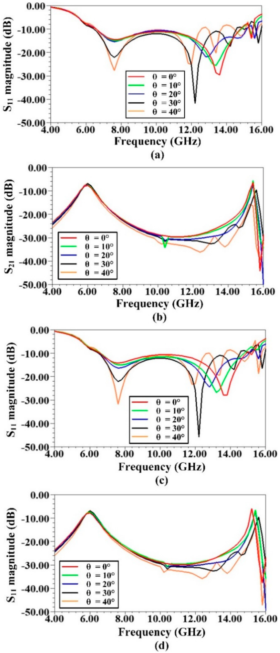
The reflection/transmission characteristics of the unit cell for oblique angle incidences are shown in
Figure 3, and the results are given for both TE and TM wave polarizations. All results were plotted for AP
L = 5.5 mm (the center of the gradient, see
Table 1). From
Figure 3a,b depicting TE wave polarization, it is evident that despite the variation of the angle of incidence, low magnitudes (less than −10 dB) of reflection as well as transmission are still being obtained over a wide band (starting from about 7 GHz and beyond). For the TM case, a similar behavior is also observed, and can be witnessed from
Figure 3c,d. It can be asserted that the PRS backed AFSS, as an absorber, shows good angular stability.
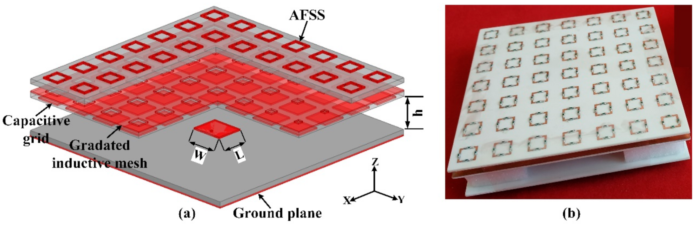
A 7 × 7 unit cell array was mounted on top of a rectangular patch antenna, as shown by the simulated model in
Figure 4a, and experimental prototype in
Figure 4b. Cavity height (h) is 13 mm (~λ/4). The coaxial feed offset is 3.2 mm from the patch center towards +
x-axis. All dielectric laminates are of Rogers RO4003C material (ε
r = 3.55 (design), thickness 1.52 mm). Gradient implementation is along y-axis, with the AP
L values and the corresponding reflection phases shown in
Table 1.
3. Simulation and Experimental Results
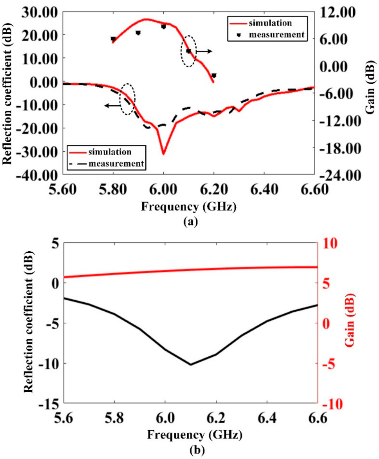
Simulated vs. measured S
11 response of the proposed antenna is shown in
Figure 5a. Sharp resonance was achieved at 6 GHz, and impedance bandwidth (−10 dB) is 443 MHz (7.26%). Gain vs. frequency plot of the proposed antenna is also shown in
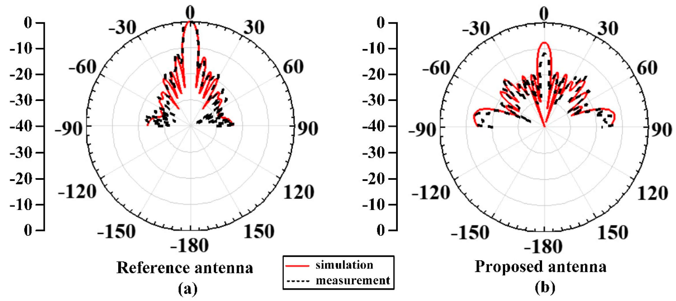
Figure 5a. At operating frequency, peak gain achieved is ~9.4 dB. Gain bandwidth (3 dB) is from 5.82 GHz to 6.08 GHz (4.37%). A satisfactory agreement exists between simulated and measured results, establishing the accuracy of simulation and fabrication.
Figure 5b illustrates the S
11 and gain vs. frequency response of the reference antenna (antenna without the superstrate assembly). It can be seen that −10 dB resonance of the reference antenna is slightly right-shifted as compared to the resonance of the proposed antenna. This frequency shifting is attributed to the input impedance variation when the dielectric superstrate is absent. Meanwhile, the gain of the proposed antenna is 6.4 dB at operating frequency, and is increased by 3 dB in the presence of the superstrate assembly.
Figure 6a illustrates the far field H-plane radiation pattern at 6 GHz. Off-broadside radiation at an angle of −38° was achieved, deflected in the elevation plane, with side lobe levels (SLLs) ~10 dB below the maximum. Deflection angle is aligned to the axis in which the increase of aperture size (gradient) is implemented. E-plane pattern is shown in
Figure 6b. Manufacturing tolerances as well as positioning errors during measurements can be the cause of difference between simulated and measured patterns. The far field H-plane and E-plane radiation patterns of the reference antenna are shown in
Figure 6c,d, respectively. It can be witnessed that without the superstrate, the antenna radiates towards broadside. The radiation pattern plotted at various frequencies is shown in
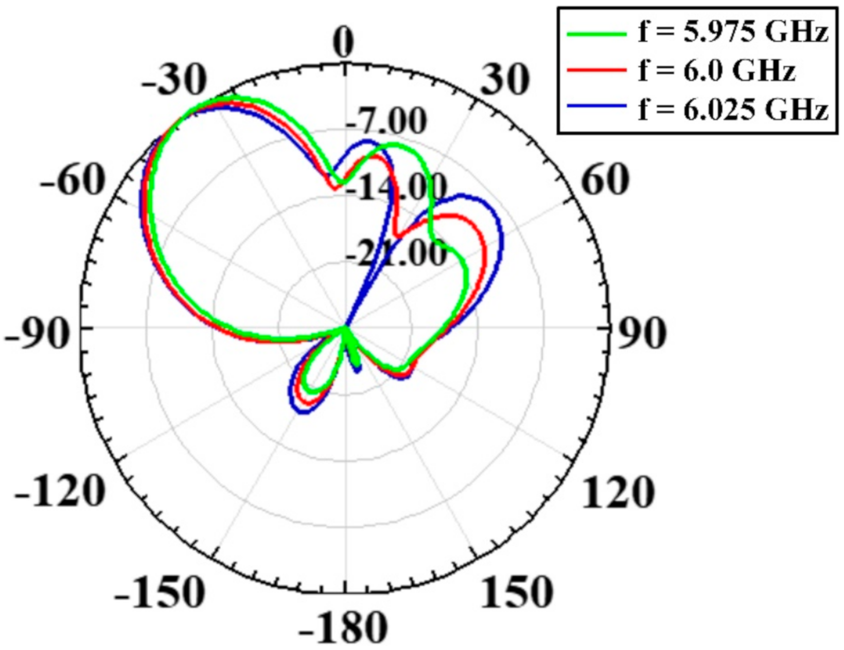
Figure 7. The pattern is satisfactorily uniform over a bandwidth of 50 MHz, although a little deterioration of the SLLs occurs.
The reference antenna’s radiation efficiency at operating frequency is 95%; however, the proposed antenna’s efficiency diminishes to 60%. The primary reason for this efficiency reduction can be deduced from
Figure 2b, where the S
21 transmission is shown. It notes that since the unit cell/superstrate is a passive structure, its S
12 transmission response would also be exactly identical to
Figure 2b. Thus, at operating frequency, the transmission magnitude is −6 dB for the AP
L value of 6.6 mm (the largest aperture dimension listed in
Table 1), and the transmission magnitude reduces with the decreasing aperture values. This means that the loss of energy of the radiated wave occurs within the superstrate structure, and thus diminishes the radiation efficiency.
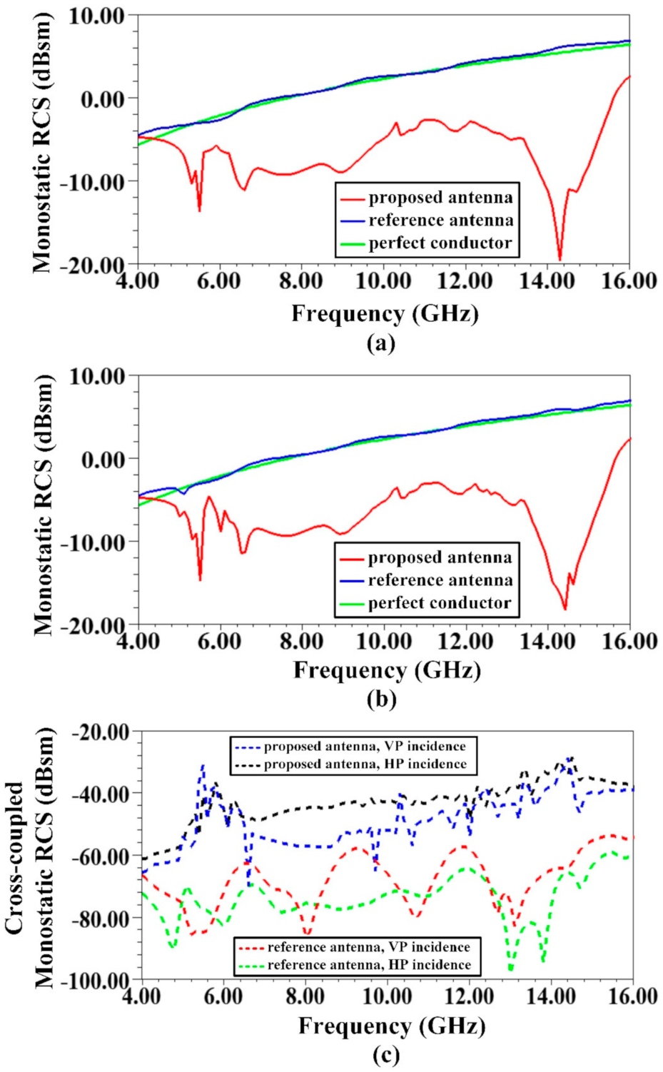
To validate the antenna’s scattering performance, simulated monostatic RCS plotted against frequency for normal illumination of the incident wave is shown in
Figure 8. Vertically polarized (VP) and horizontally polarized (HP) incident wave cases are respectively given in
Figure 8a,b. Also shown in the figures is the RCS response against frequency of the reference antenna, which has the same lateral dimensions as of the proposed antenna. In addition, the calculated RCS frequency response of a perfect conductor of similar size is also presented. The calculation is based on the relation given as: σ
C = 4πa
2/λ
2, where σ
C is RCS of the perfect conductor, a is the area of the conductor, and λ represents wavelength of interest. For both polarizations shown in
Figure 8a,b, wideband RCS reduction was achieved, including in-band frequencies. RCS reduction bandwidth (BW) extends over 4–16 GHz (120%), and an almost identical frequency response was achieved for the VP and HP wave incidences. This is owed to the symmetric unit cell design. For VP, average RCS reduction over the bandwidth is about 8.5 dB, and for HP, it is about 8.8 dB. Maximum achieved RCS reduction values are 25 dB (for VP) and 24 dB (for HP), respectively, appearing at 14.3 and 14.4 GHz value. The results shown in
Figure 8a,b correspond to the co-polarized RCS frequency performance. The cross-coupled RCS monostatic performance of reference as well as proposed antenna, considering VP and HP wave incidences, is displayed in
Figure 8c. As can be seen, the cross-coupled radar echoes are significantly low. The cross-coupled RCS performance of the proposed antenna obeys the cross-coupling reflection results presented for the unit cell in
Figure 2a. Hence, the function of the absorber for reflectivity suppression is validated.
The results presented in
Figure 8 are for the case of 50 Ω antenna termination. This is because for most of the practical cases, the antenna would be matched terminated to its transmitter (Tx) or receiver (Rx). However, simulations for the cases of open/short terminations (worst case scenarios) were also performed for the proposed antenna, and it was observed that there was no significant change among different cases (short/open/matched). This might be due to the reason that the short or open primarily affects the antenna mode scattering, which is a function of antenna gain given as [
41]:
where σ
ANT represents antenna mode scattering, G is antenna gain, Γ is reflection coefficient, and λ is the wavelength at the frequency of interest. The out-of-band frequencies will be unaffected by open/short terminations as these frequencies are being significantly absorbed at the absorber surface (and hence leave an insignificant energy that would reach the antenna surface). For the in-band frequencies, the in-band absorption is impaired (as evident from
Figure 2a,b), but the in-band antenna mode scattering (frequencies reflected from the mismatched load and getting re-radiated by the antenna) would still be insignificant as the gain towards broadside is considerably low.
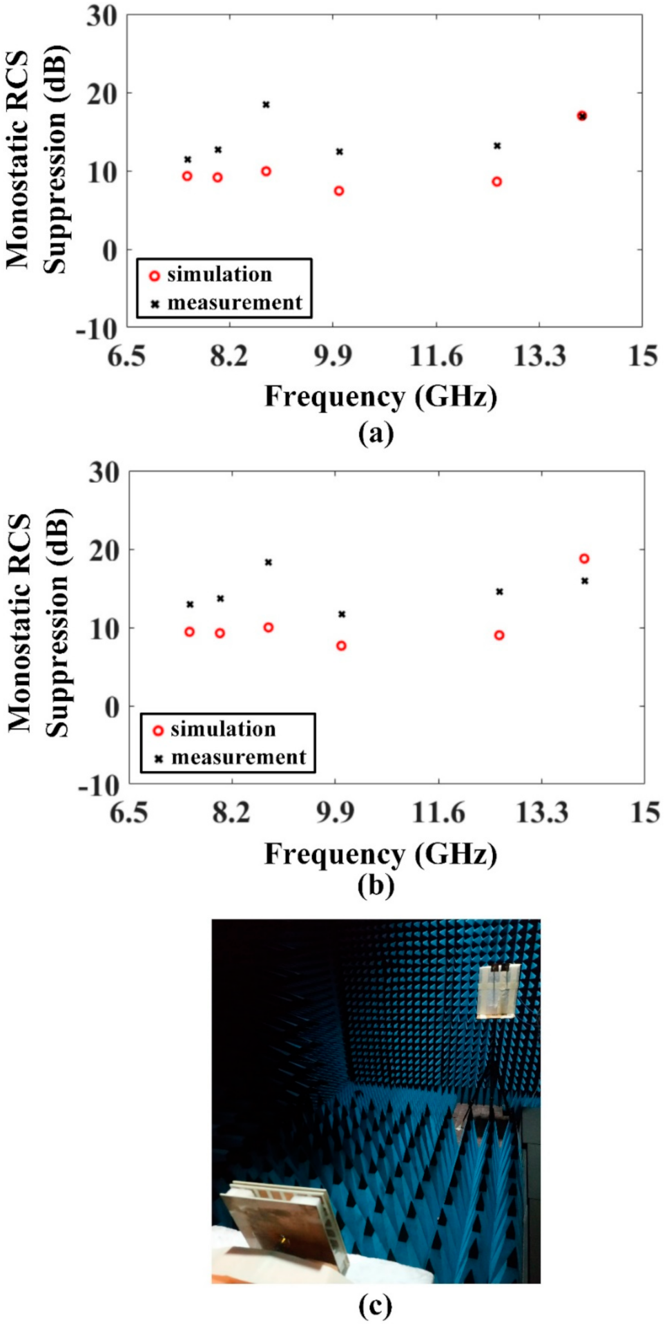
The measurement of frequency response of monostatic RCS was performed using two sets of in-lab developed parabolic reflector antennas that had lambda/2 dipole as their excitation source. Each set contained two such antennas (one for transmit (Tx) and one for receive (Rx) operation). Within the desired frequency range, six different frequencies were tested. In comparison to horn antennas, the size of these antennas is smaller; hence, in a real scenario, they can better replicate the ideal monostatic simulation setup—a merit that is worth noting.
Figure 9a represents the simulated vs. measured monostatic RCS suppression for VP incident wave, whereas
Figure 9b displays the same for the HP incident wave. The measurement setup is displayed in
Figure 9c. As evident from
Figure 9a,b, an agreeable correlation is found between the simulated and measured results; in fact, the measured suppression performance is superior for most of the frequency points. The details of tested frequencies with a comparison between simulation and measured RCS suppression levels are exhibited in
Table 2. The measured mean suppression surpasses the simulated values. From these measurements, it can be asserted that the design verification stands as successful.
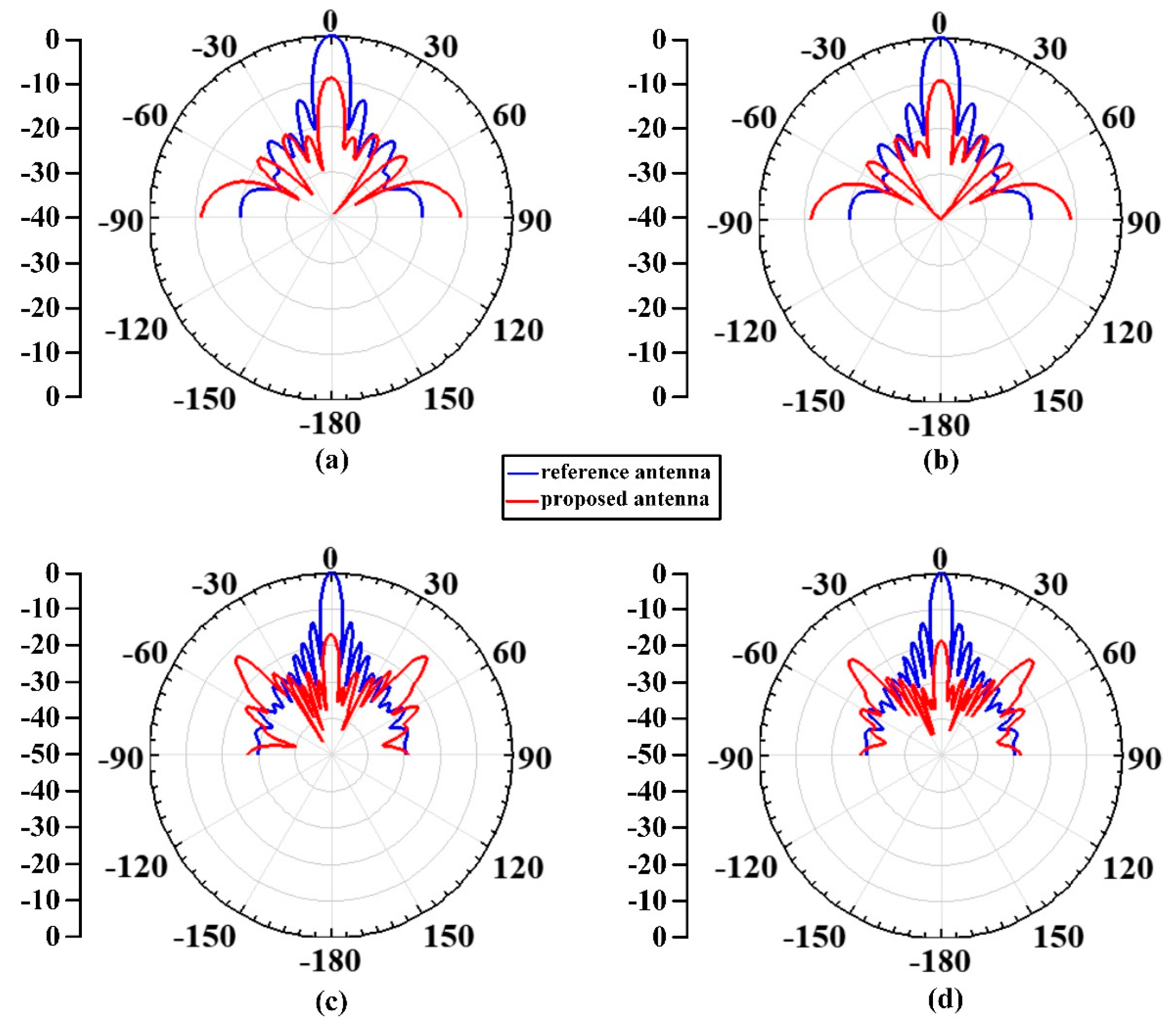
The monostatic RCS was also investigated as a function of incidence angle (−90 to +90) to determine the angular stability of the proposed design.
Figure 10a,b show normalized y–z plane plots for VP incident wave, respectively, for reference antenna and proposed antenna. Similarly,
Figure 11a,b show normalized x–z plane plots for HP incident wave, respectively, for reference antenna and proposed antenna. Measured results of the above are presented along with, and depict, a satisfactory correlation with the simulation results. All of these results were plotted at 10 GHz. From
Figure 10 and
Figure 11, RCS reduction occurs over about ±15° angular span. All presented RCS results are for antennas terminated with matched load.
In
Figure 12, the simulated monostatic RCS angular responses of the reference and proposed antennas are presented for some more frequencies.
Figure 12a illustrates the y–z plane RCS plots for a VP incident wave at 7.6 GHz, while
Figure 12b illustrates the x–z plane RCS plots for an HP incident wave at 7.6 GHz. Similarly,
Figure 12c illustrates the y–z plane RCS plots for a VP incident wave at 14 GHz, while
Figure 12d illustrates the x–z plane RCS plots for an HP incident wave at 14 GHz. For the 7.6 GHz frequency, the RCS reduction in both planes occurs over an angular span of ±22°, and it increases to ±28° at 14 GHz. It is inferred that as the broadside RCS reduction increases, the angular span over which the RCS reduction is achieved, increases as well. Furthermore, it can be observed from
Figure 10,
Figure 11 and
Figure 12 that in comparison to the reference antenna, the low RCS performance of the proposed antenna gets impaired towards wider off-broadside angles. In fact, the reflectivity even increases at too far-off angles. This increase may be attributed to the vertical dimension of the proposed antenna, as it is a Fabry–Perot cavity, while the reference antenna is a single layer planar antenna. Thus, it is important to mention that although the proposed antenna’s main beam (radiation) is deflected towards off-broadside direction, the wideband low RCS performance of the proposed antenna is dominantly towards broadside angles only. Furthermore, as explained by the working of the unit cell in
Section 2, the off-broadside peak radiation was achieved by implementing the phase gradated PRS, while the wideband broadside RCS reduction is a result of the PRS backed AFSS. Therefore, the antenna may potentially be used in those low observable military applications where it is desired to have communication in an off-broadside direction.
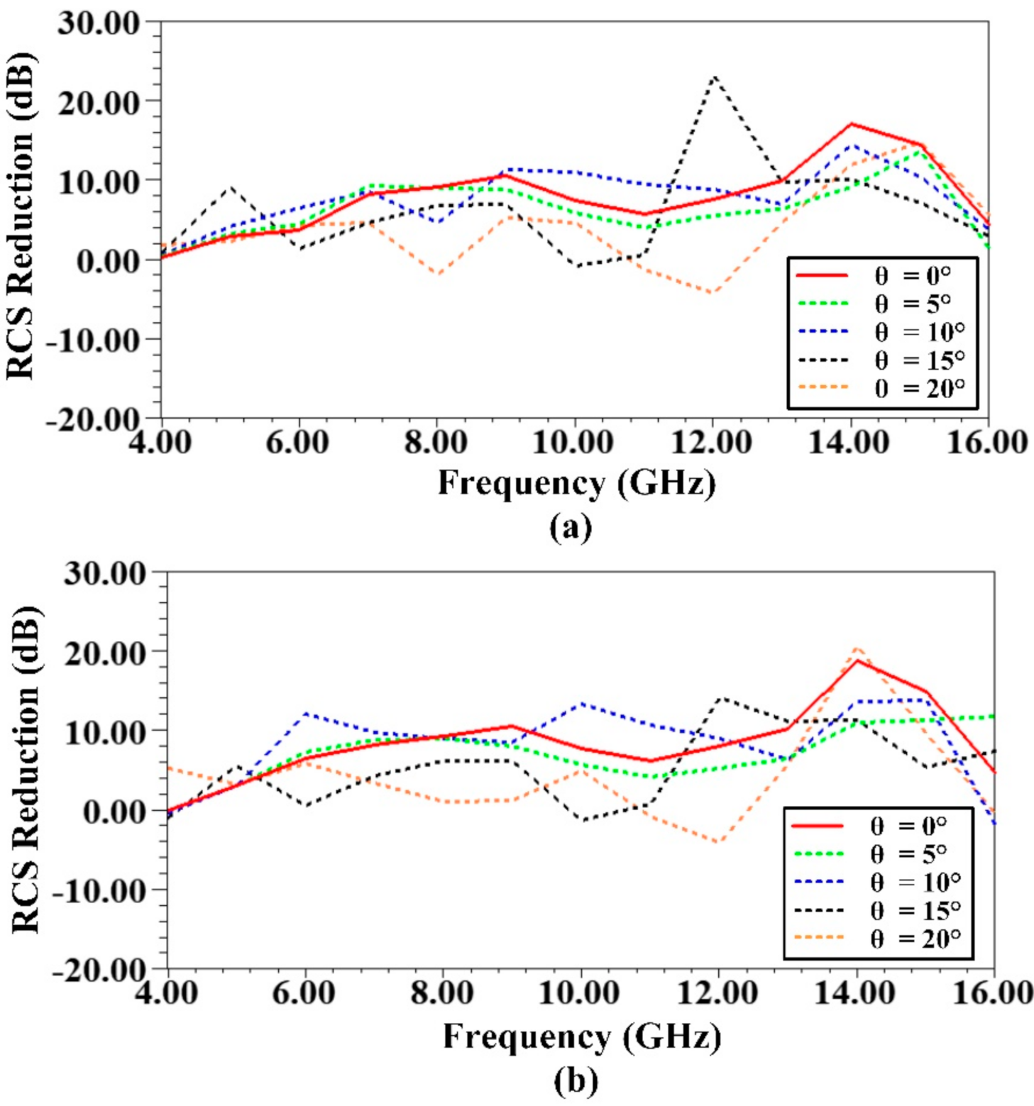
The monostatic RCS reduction for oblique angle incidence is shown in
Figure 13. For the VP wave incidence, RCS reduction is shown in
Figure 13a, and for the HP wave incidence, the RCS reduction is shown in
Figure 13b. From the curves, it can be observed that for the incident angles of 5° and 10°, the performance is close to that of 0° case (bore-sight). For the wave incidence of 15°, the RCS reduction for both polarizations is close to 0 dB at the frequency points of 6, 10, and 11 GHz. It is important to mention that at these frequencies, both the proposed as well as the reference antennas realize nulls (or steep slopes just around the nulls) in their monostatic reflectivity patterns. For the incidence angle of 20°, the average RCS reduction becomes somewhat lower, and the RCS reduction value at 12 GHz is a little compromised. Thus, it can be asserted that the overall angular stability of the proposed design is slightly less than ±20°.
To have further insight into absorption as well as off-broadside radiation mechanism, surface E-field plots are presented in
Figure 14. The log magnitude of E-field plotted on the absorber surface is show in
Figure 14a. The plot is for a VP (x-polarized) incident wave, and at the frequency of 9 GHz. By inspection of
Figure 14a, the spots of higher field intensity are easily identifiable. This field appears across the gaps in the metallic loops where resistors are present. The energy dissipation of the incident field occurs as heat within these resistors, thereby leading to the absorption of incident wave at the surface. Identical field plot is expected for an HP incident wave, except that the higher field intensity spots would now appear across the other two gaps for every loop. Likewise, field overlay plot on the surface containing gradated apertures (phase gradient surface) is shown in
Figure 14b. This plot represents the field induced as a result of the wave radiated from the patch antenna (6 GHz frequency). It can be witnessed that a steady variation of surface E-field appears along the y-axis, in that, the E-field concentration increases gradually along –y-axis. This validates the mechanism behind beam deflection operation.


