Experimental Study on the Compression Behavior of Grouted Rock with Bi-Directional Penetrating Crack


1
School of Civil Engineering, Central South University, No.22 South Shaoshan Road, Changsha 410075, China
2
School of Civil Engineering, Changsha University of Science & Technology, No.960 2nd Section South Wanjiali Road, Changsha 410004, China
3
School of Civil Engineering, Central South University of Forestry and Technology, No.498 South Shaoshan Road, Changsha 410004, China
*
Author to whom correspondence should be addressed.
Appl. Sci. 2021, 11(2), 537; https://doi.org/10.3390/app11020537
Submission received: 16 December 2020
/
Revised: 5 January 2021
/
Accepted: 6 January 2021
/
Published: 7 January 2021
(This article belongs to the Section Civil Engineering)
Abstract
:Grouting is a common method of reinforcing fractured rock mass. The mechanical property of grouted rock is a major aspect of the reinforcement effect, which depends on the geometry of the crack, the angle (β) between the load direction and the crack, and other factors. Few studies have focused on grouted rock with bi-directional crack which can reflect well the grouting reinforcement in the stratum with developed fractures. To explore the grouting effect on fractured rock mass, uniaxial compression tests were carried out on grouted rock samples with different bidirectional widths (t) and angles cracks. The results showed that: (1) when the β was 30°, the failure mode was sliding along the interface of rock and grout, when the β was 45°, the failure mode was composite failure mode, and when the β was 0°, 60°, or 90°, the failure mode was typical intact rock failure mode; (2) when the β increased from 0° to 90°, the uniaxial compressive strength (UCS) decreased and then increased again; (3) when the β was 30°, the UCS had nothing to do with the grout thickness, and when the β was not 30°, the greater the grout thickness, the greater the compressive strength and the ultimate energy storage capacity. The test results can provide reference for grouting reinforcement construction and design in the underground excavation process.
1. Introduction
Grouting is a common and effective reinforcement measure in fractured rock mass or rock mass with developed joints and cracks. Grouting reinforcement is widely used in tunnels, dam foundations, and landslides [1,2,3]. Compared to other rock engineering technologies, grouting reinforcement has the advantages of simple operation, convenient application, and reliable application. Furthermore, grouting technology does not require complex equipment for construction and this technology incorporates the characteristics of green environmental protection [4,5,6].
Grout can fill the weak plane or joint and bond loose rock mass to form an integrated body. The mechanical properties of grouted rock are major indicators of the grouting reinforcement effect. The interface of rock and grouting slurry in the integrated body is the weak part. In view of the geometrical characteristics of interface, its shear characteristics are the key points and need to be studied first. The geometric and mechanical properties of the original joints affect the mechanical properties of the interface [7]. Saliminan et al. [8] molded artificially fractured cement-filled joints and pointed out that grouting had a positive effect on shear strength. Lu et al. [9] investigated shear fracture evolution through a series of direct shear tests on artificial sandstone joints filled with cement grout. Ma and Liu [10] proposed the peak shear strength criterion of grouting joints from the perspective of micromechanics and macro roughness. Through numerical simulations and site tests, Lee et al. [11] quantitatively studied the reinforcement effect of permeation grouting on a jointed rock mass and pointed out that the geometric and mechanical characteristics of the joints affected the grouted rock mass. Sun et al. [12] and Han et al. [13], based on the results of theoretical analyses and direct shear tests, developed a peak shear strength model. In addition, several shear tests were conducted on cemented concrete-rock joints to investigate rock-concrete interaction [14,15,16].
The interface between the grout and rock is only a part of the grouted rock, which cannot reflect the overall mechanical properties. In practice, the grout, interface, and original rock jointly bear the external force. At the same time, in the underground environment, the rock mass is more compressed rather than sheared. Therefore, the mechanical behavior of the whole grouted rock under compression is also one of the research focuses. The mechanical properties of the whole grouted rock depend on the geometry of the original cracks, the combination of the cracks and the original rock, the angle between the cracks and the principal stress, and the mechanical properties of the grout.
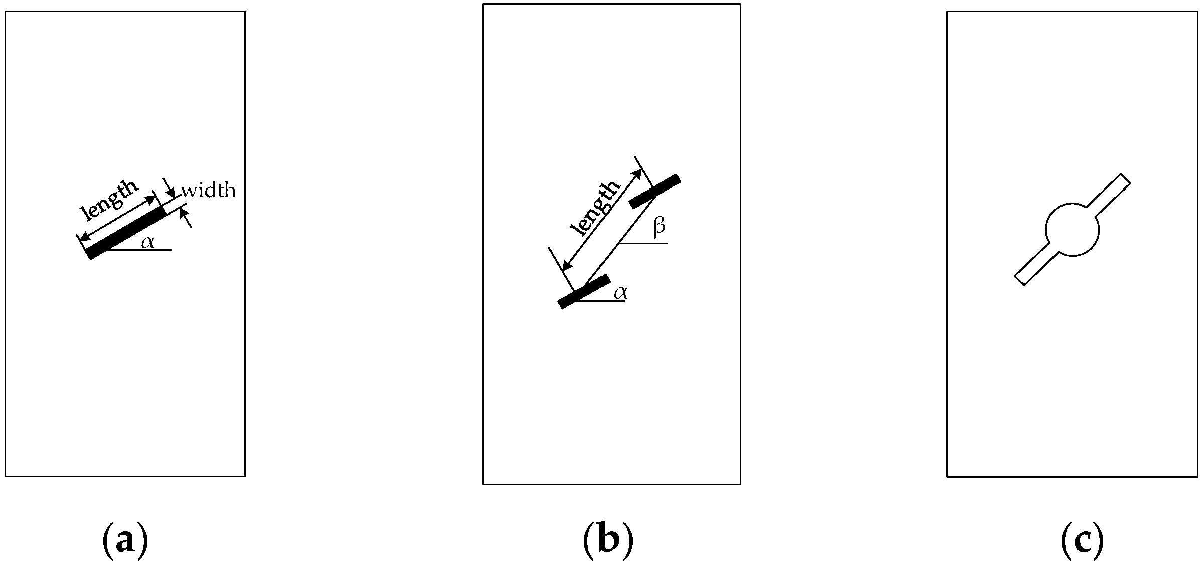
At present, there are many studies on grouted rock with single or multiple unidirectional penetrating cracks. Generally, the standard sample with prefabricated cracks is used as the experimental subject, which is shown in Figure 1. Huilin et al. [17,18,19] comparatively analyzed the compressive behavior of grouted rock samples with single unidirectional penetrating cracks (as shown in Figure 1a) of different inclination angles, length, and width before and after grouting under uniaxial compression or triaxial compression. Shuting et al. [20] compared the reinforcement effect of different grouting materials in rock mass with single crack. Zhihong et al. [21] analyzed the compression behavior of rock samples with two unidirectional penetrating cracks (as shown in Figure 1b) after grouting by particle mechanics model. Yixian et al. [22] analyzed the effect of grouting on the specimen with cavity and crack (as shown in Figure 1c) under uniaxial compression.
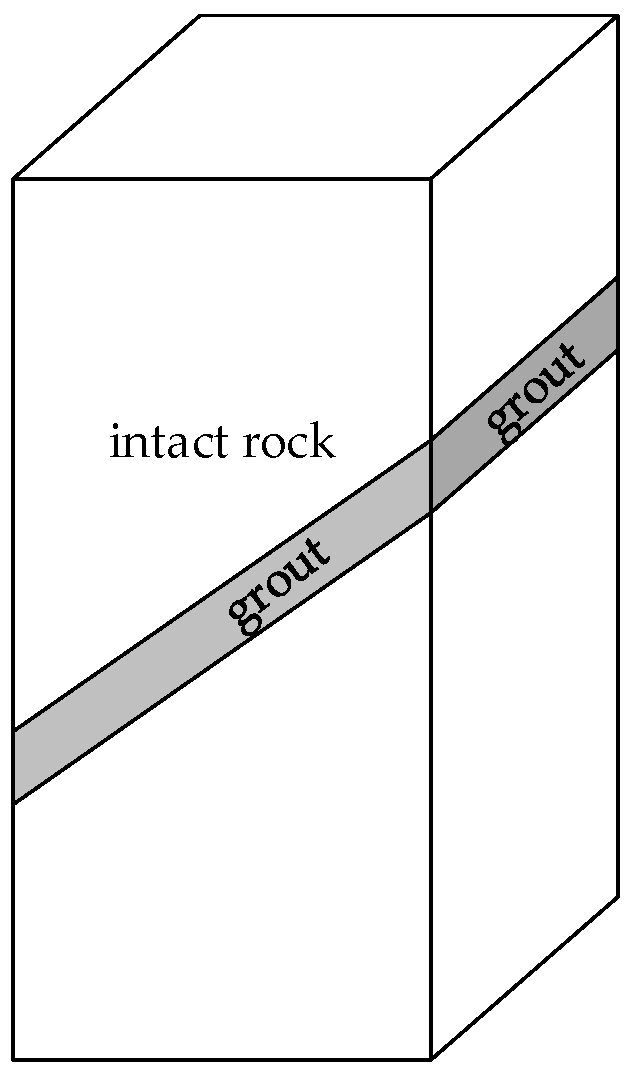
The mechanical experiments of grouted rock with unidirectional through cracks can reflect the reinforcement effect and the process of crack re-expansion at the location where the local cracks are not well developed. In the part where the cracks develop, the specimens with a bi-directional penetrating crack can better reflect the actual situation. To our knowledge, research on the compressive behavior of grouted rock with a bi-directional penetrating crack is rare. Zhibin et al. [23] analyzed fracture properties of grouted rock with bi-directional penetrating crack (as shown in Figure 2) under uniaxial compression. In Zhibin’s research, the angle between crack and principal stress and crack width were not considered.
In this research, we took the angle between crack and load direction and the thickness of grout into consideration to explore the compression behavior of grouted rock with bi-directional penetrating crack. We prefabricated different widths and different inclined angles of bi-directional cracks on the rock sample and performed grouting reinforcement to obtain the grouted rock. The uniaxial compression tests were carried out to analyze the failure mode and compression strength of the grouted rock with the change of the crack type, so as to provide reference for the design and construction of grouting reinforcement in underground engineering.
2. Materials and Methods
2.1. Samples Preparation
The rock used in the test was from a foundation pit project in Changsha. The main mineral composition was calcite, quartz, and sericite, as well as a small amount of kaolinite and montmorillonite. The average density was 2350 kg/m3 and the uniaxial compressive strength was 27 MPa. All samples were taken from the same intact block.
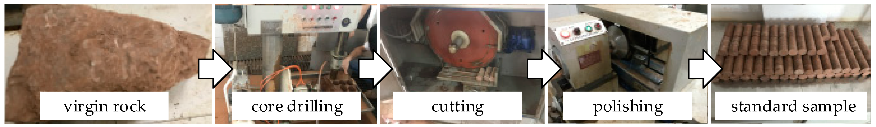
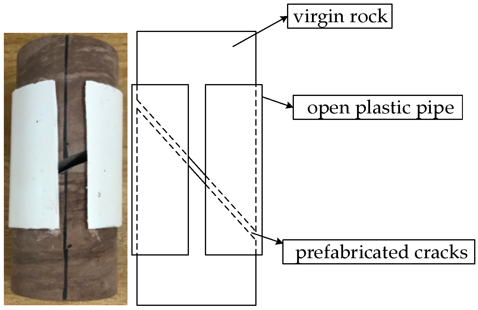
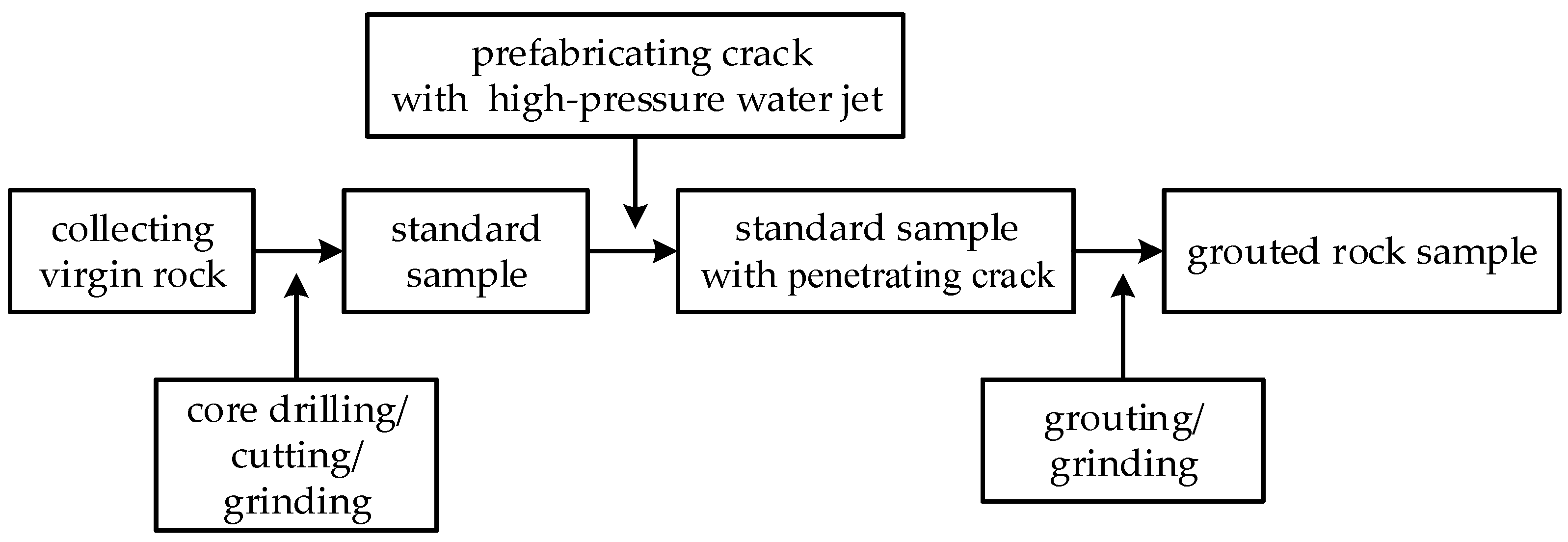
The sample preparation was divided into four steps: first, standard rock sample was made and the penetrating crack was processed, then the crack was filled, and finally the sample was polished again. The standard sample was a cylinder with a diameter of 50 mm and a height of 100 mm, and the crack was cut by high-pressure water jet. The production process of standard samples is shown in Figure 3. The crack width was controlled by open pipe to fix the spacing, which is shown in Figure 4. The sample production flow chart is shown in Figure 5.
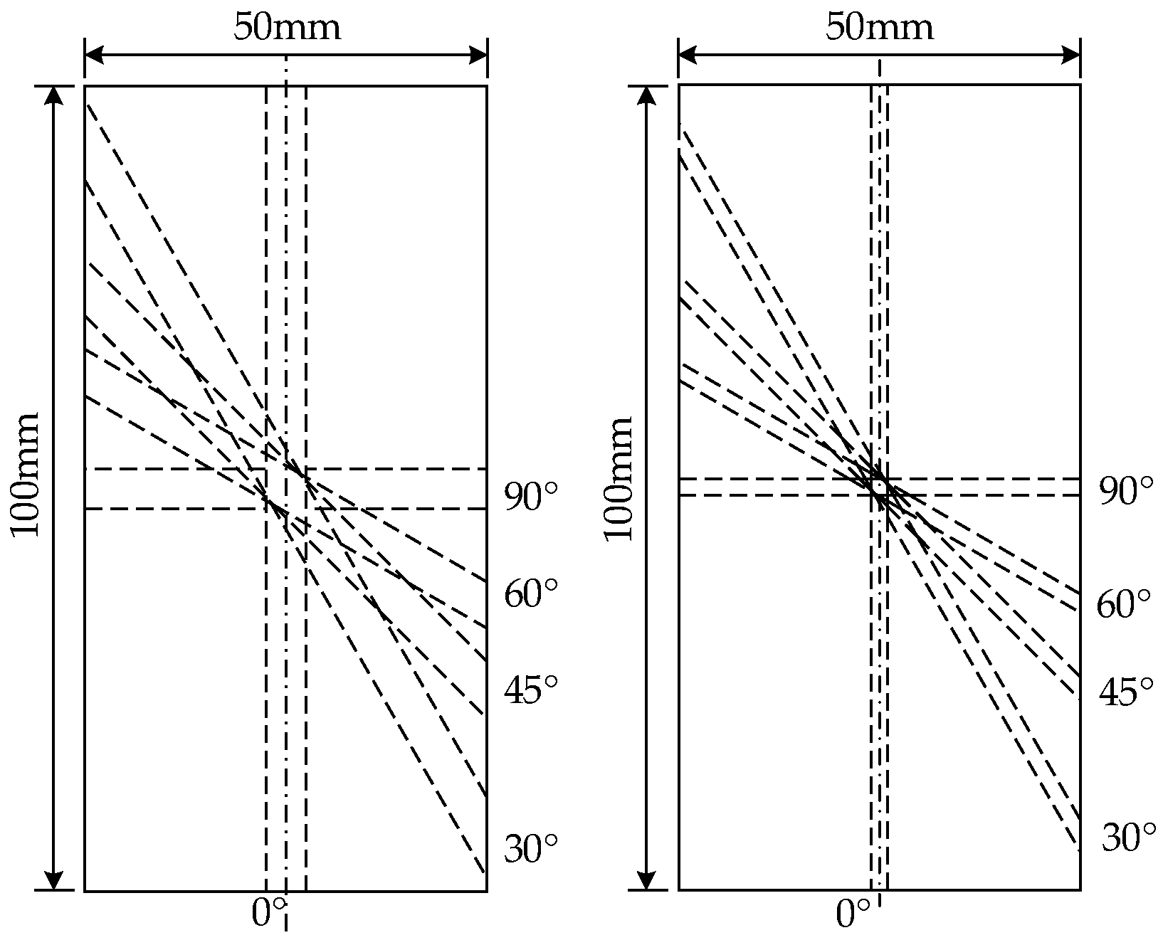
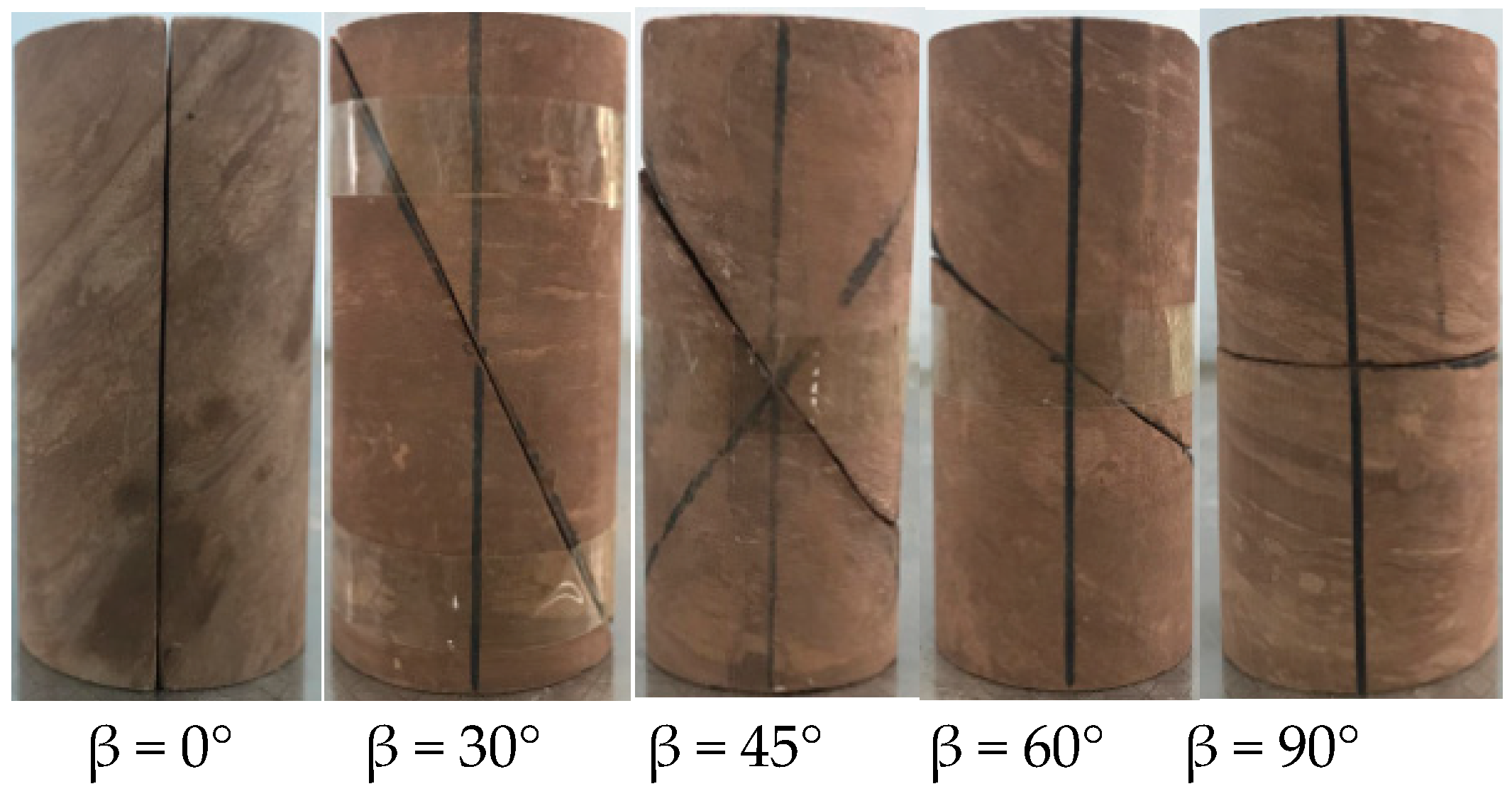
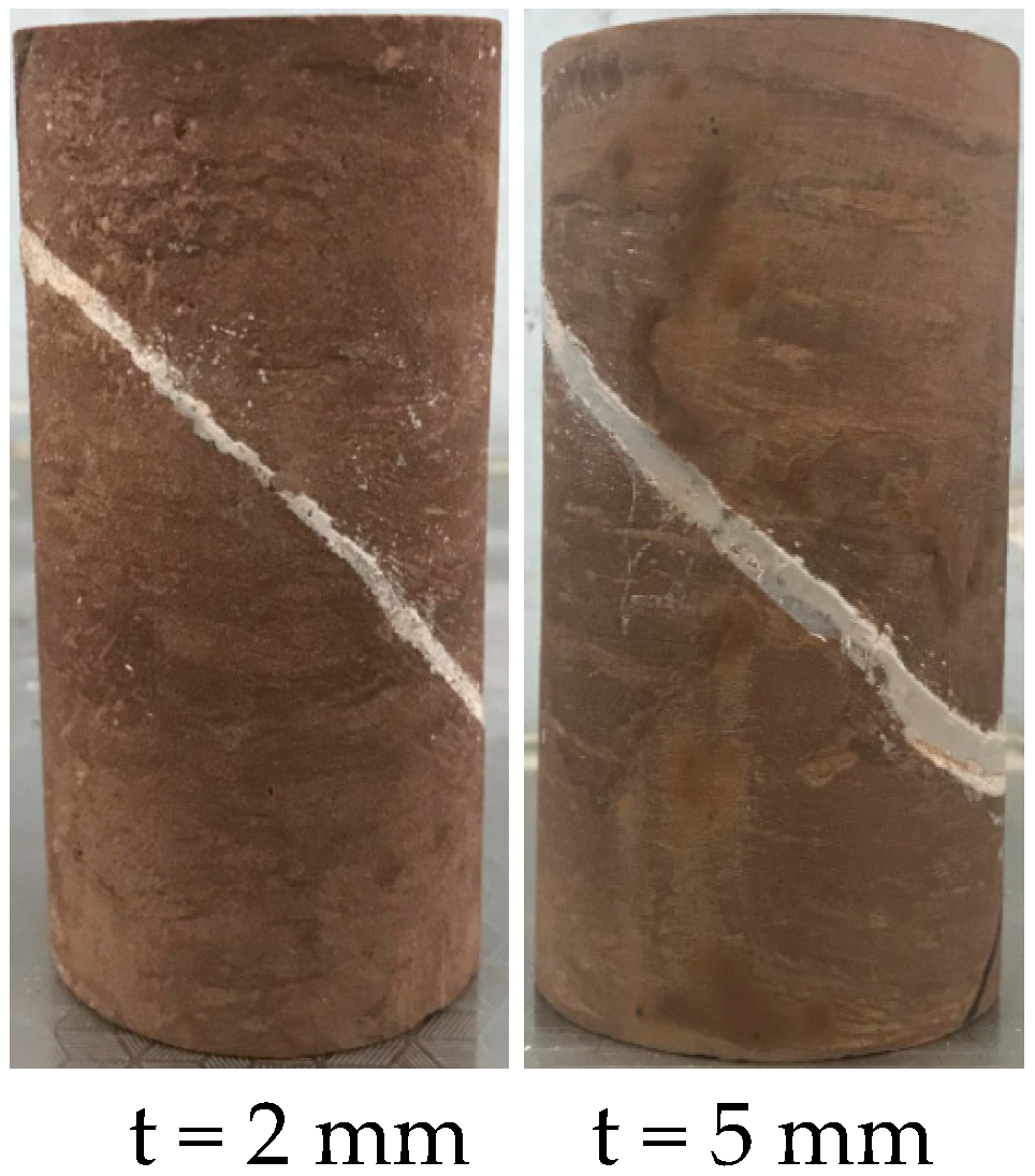
In order to study the compression behavior of grouted rock with different crack widths t and different angles β between loading direction and crack, t was taken 2 mm and 5 mm and β was taken 0°, 30°, 45°, 60°, and 90°. The schematic diagram of the specimen is shown in Figure 6. The actual samples with prefabricated crack are shown in Figure 7. The grouting material was geopolymer material which was developed by our research group. The precursor is a mixture of metakaolin and fly ash and the activator is alkali activator, which is mixed with sodium hydroxide and sodium silicate. It was characterized by good working performance and high early strength. The uniaxial compressive strength of the slurry can reach 25 MPa within 24 h, the strength increase stops after 72 h, and the final strength can reach 35 MPa. The fluidity of fresh slurry can reach more than 220 mm. This grouting material can reduce the curing time. The grout was injected into the crack through a syringe. The actual grouted rock samples are shown in Figure 8. There were three samples for each combination type (combination of angle and thickness), and a total of 30 samples were prepared.
2.2. Experiment Scheme
The uniaxial compression experiment was carried out using the Mechanical Testing System (MTS). The loading process was carried out at a rate of 0.5 MPa/s until the sample was broken.
3. Results
3.1. Failure Mode
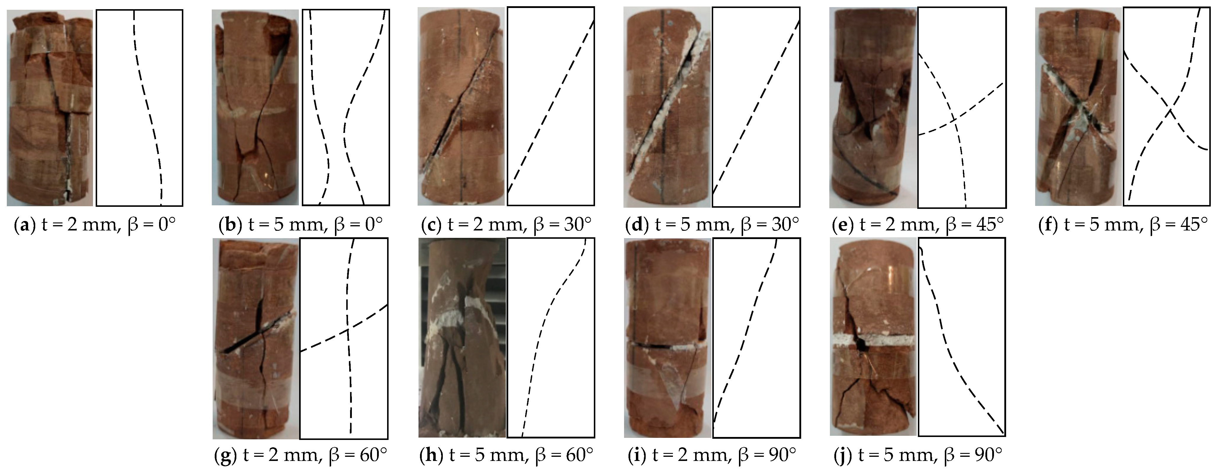
Failure modes of natural intact rock samples under uniaxial compression include shear failure, tensile failure, and composite failure. Compared with intact rock samples, the grouted rock contains a weak interface and concretion after grouting material solidified, both of which affect the failure mode of the grouted rock.
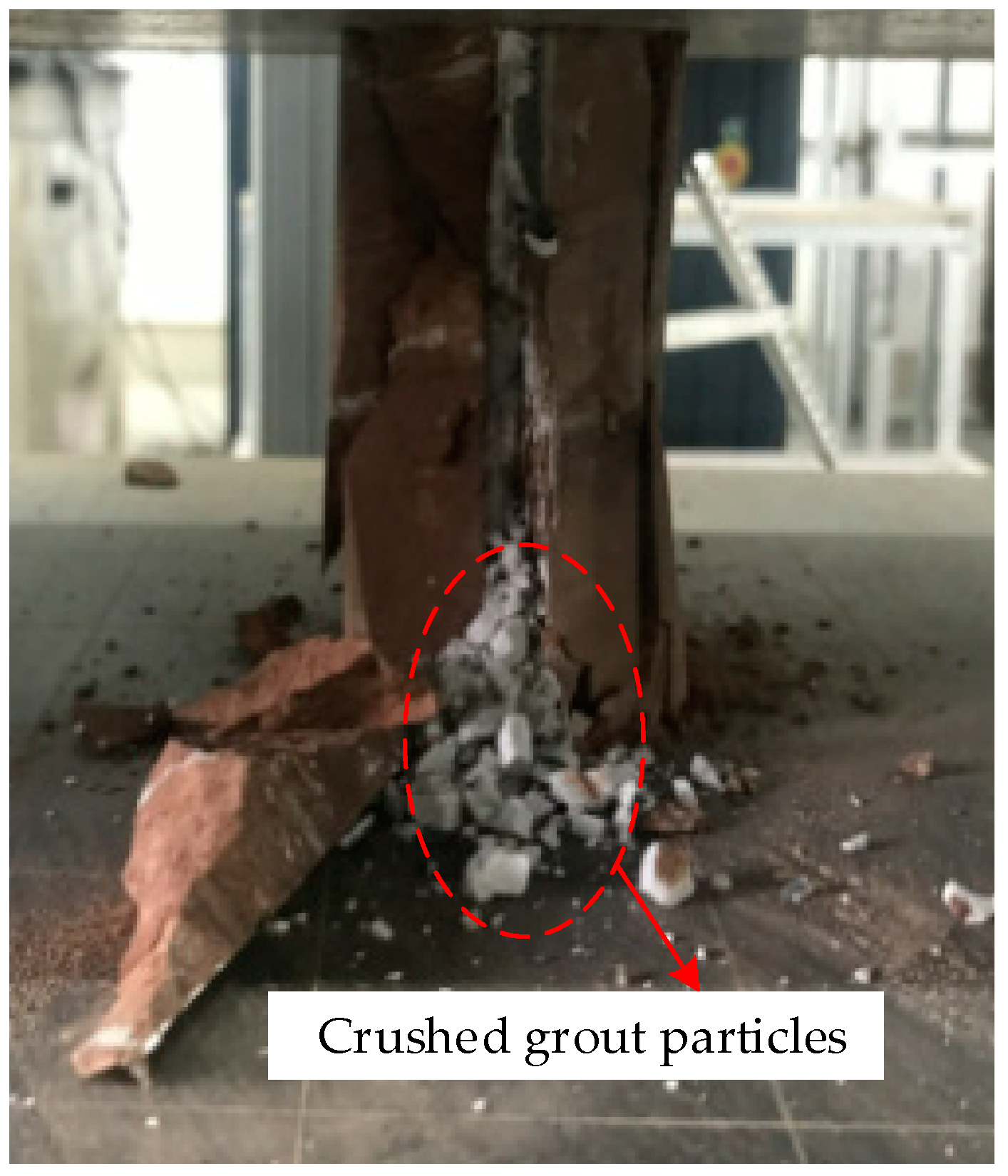
Figure 9 shows the failure mode of the samples under uniaxial compression. From Figure 9a,b, it can be seen that two types of fracture cracks generated, one is the interface of slurry and rock, and the other is the tensile failure crack of the original rock itself. At the same time, the fracture was observed during the test. During the test, it was observed that the slurry was crushed and broken into particles, and only part of the slurry was attached to the rock. When β = 0°, there was no friction between the slurry and the rock, but only the cohesive force. In the process of compression, due to the deformation coordination, the bond between the slurry and the rock first failed. The sample was divided into “two parts” from the interface. The slurry could not bear enough pressure due to the “oblate” shape and it quickly collapsed into granular shape, which is shown in Figure 10. Then, two parts of the rock sample were individually stressed.
From Figure 9c,d, it can be seen that when β = 30°, the failure mode of grouted rock was sliding along the interface, independent of the fissure thickness. Compared with the intact rock, the interface was still the weak part in the whole sample, and the slurry itself did not appear obviously damaged.
According to Figure 9e,f, when β = 45°, the main cracks developed through the slurry and formed coherent cracks, and the broken block slid down along the interface.
According to Figure 9g,h, when β = 60° and t = 5 mm, the integrity of the grouted rock was stronger than that when t = 2 mm, the failure mode was the splitting of sample, and the crack developed through the slurry to form a continuous crack.
According to Figure 9i,j, when β = 90°, the sample showed integrity and the typical shear failure mode, similar to the intact sample. During the compression process, there was no slip phenomenon at the interface.
3.2. Uniaxial Compressive Strength
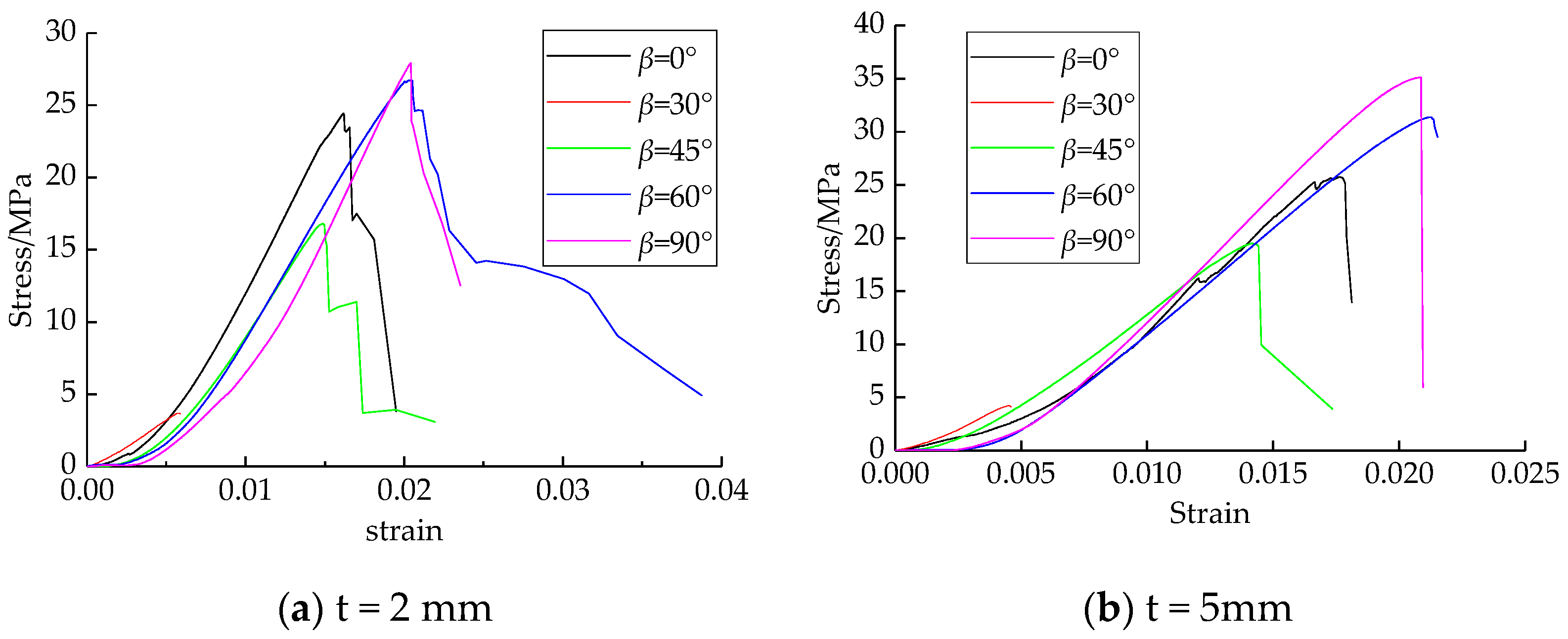
The main factors affecting the whole grouted rock mechanical strength include the original rock mechanical strength, the slurry mechanical strength, the bond force of the interface between the slurry and rock, and the combination form of the slurry and original rock. Figure 11 shows the stress-strain curves of the grouted rock with the conditions of different crack thickness and different angle between load direction and crack.
As shown in Figure 11, the brittleness of the grouted rock with the slurry thickness of 5 mm is higher than that of the grouted rock with the slurry thickness of 2 mm. The reason is that the slurry brittleness is higher than the original rock. With the increase of volume proportion of the slurry in the grouted rock, the brittleness of the grouted rock is more obvious than the original rock.
When β = 30°, the stress-strain curve of the grouted rock is nearly linear. The reason is that its failure slides along the interface instead of compressive shear failure. Under the other angle conditions, the stress-strain curve is S-shaped, which is similar to complete natural rock samples. In the process of uniaxial compression, with the increase of load, the deformation process goes through four stages: slow increase, linear increase, rapid increase, then abrupt increase.
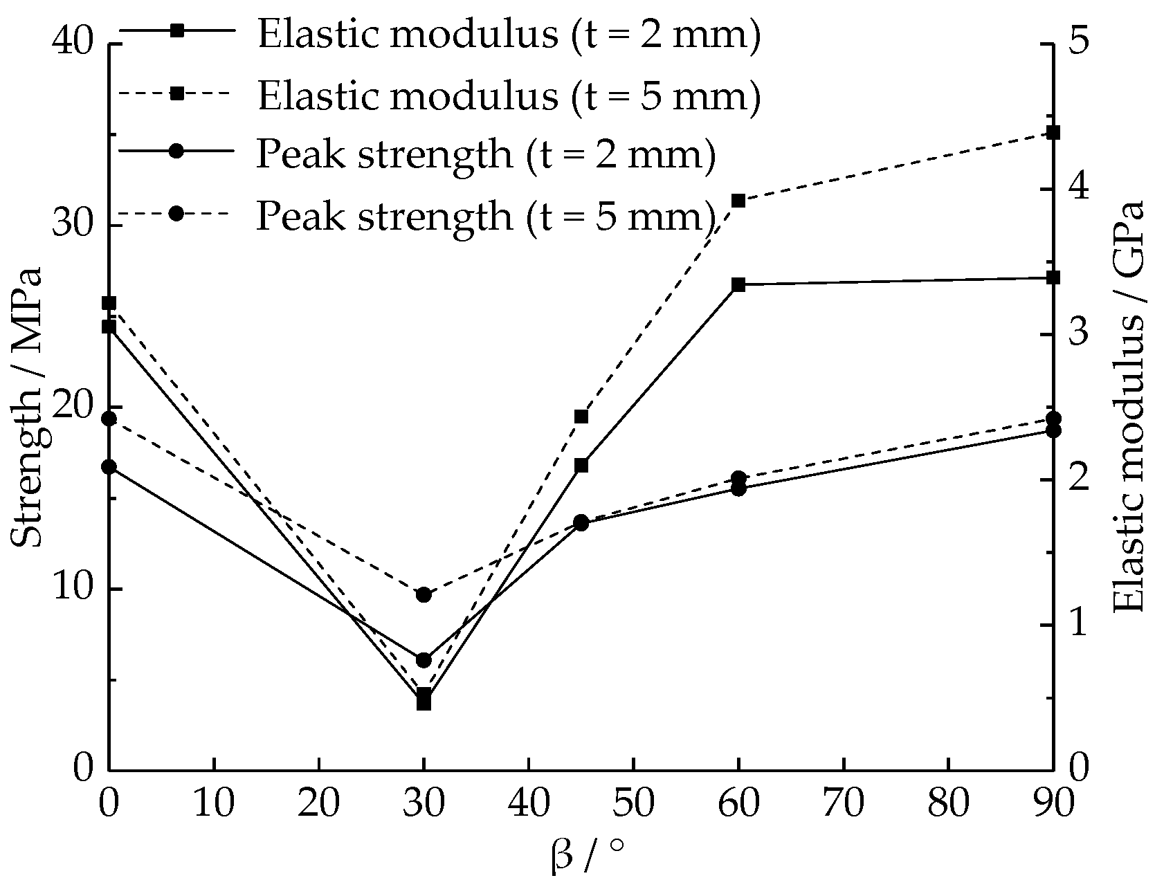
Because of the weak interface, the grouted rock showed anisotropic mechanical properties under uniaxial compression. As shown in Table 1, with the increase of the crack width, the grouted strength increases, but the peak strain changes little. As shown in Figure 12, with the change of the angle between load direction and crack, the grouted rock mechanics present a U-shaped change similar to anisotropic rock mass. When β = 90°, the strength of reinforced composite, peak strain, and elastic modulus reached maximum. When β = 30°, the strength of reinforced composite, peak strain, and elastic modulus reached minimum.
3.3. Energy Analysis
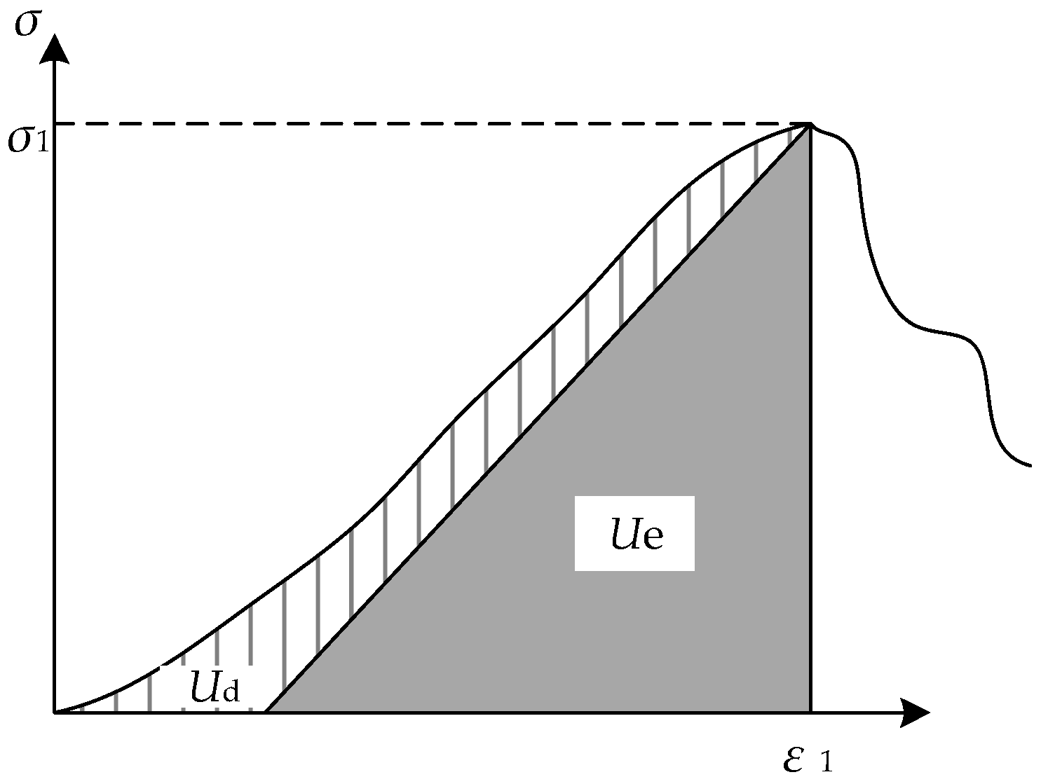
The process of uniaxial compression is the process of energy accumulation and release in the sample. It is assumed that there is no energy exchange with the outside world except the compression energy input. Before the samples reach the peak stress, energy is stored in two forms, one is in the form of strain energy, and the other is consumed by the initiation and propagation of microcracks and macrocracks. When the input energy exceeds the capacity of the samples, the strain energy will be released suddenly, accompanied by the failure of the samples. According to the first law of thermodynamics, before the samples reach the peak stress, the total energy input U0 is the sum of elastic strain energy Ue and dissipation energy Ud. U0, Ue, and Ud can be calculated from Equations (1)–(3). The typical stress-strain curves and energy relationships of natural intact rock samples are shown in Figure 13.
where σ1 is peak stress, ε1 is peak strain, and E is elastic modulus.
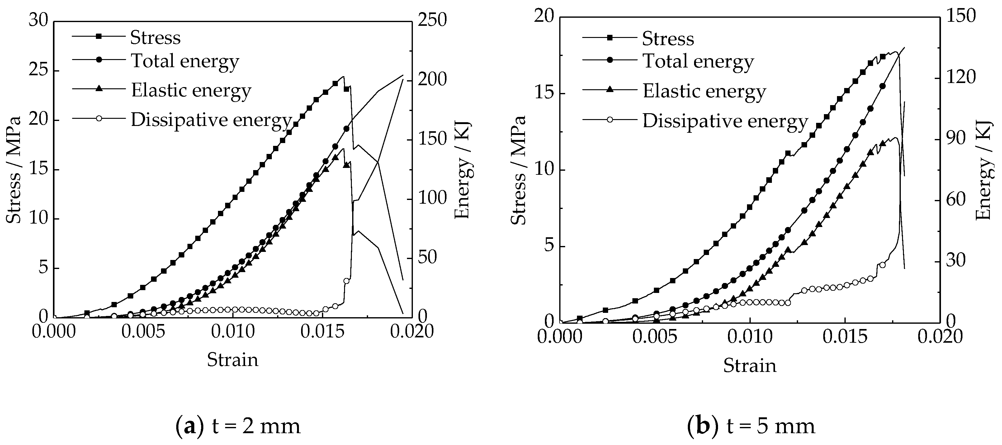
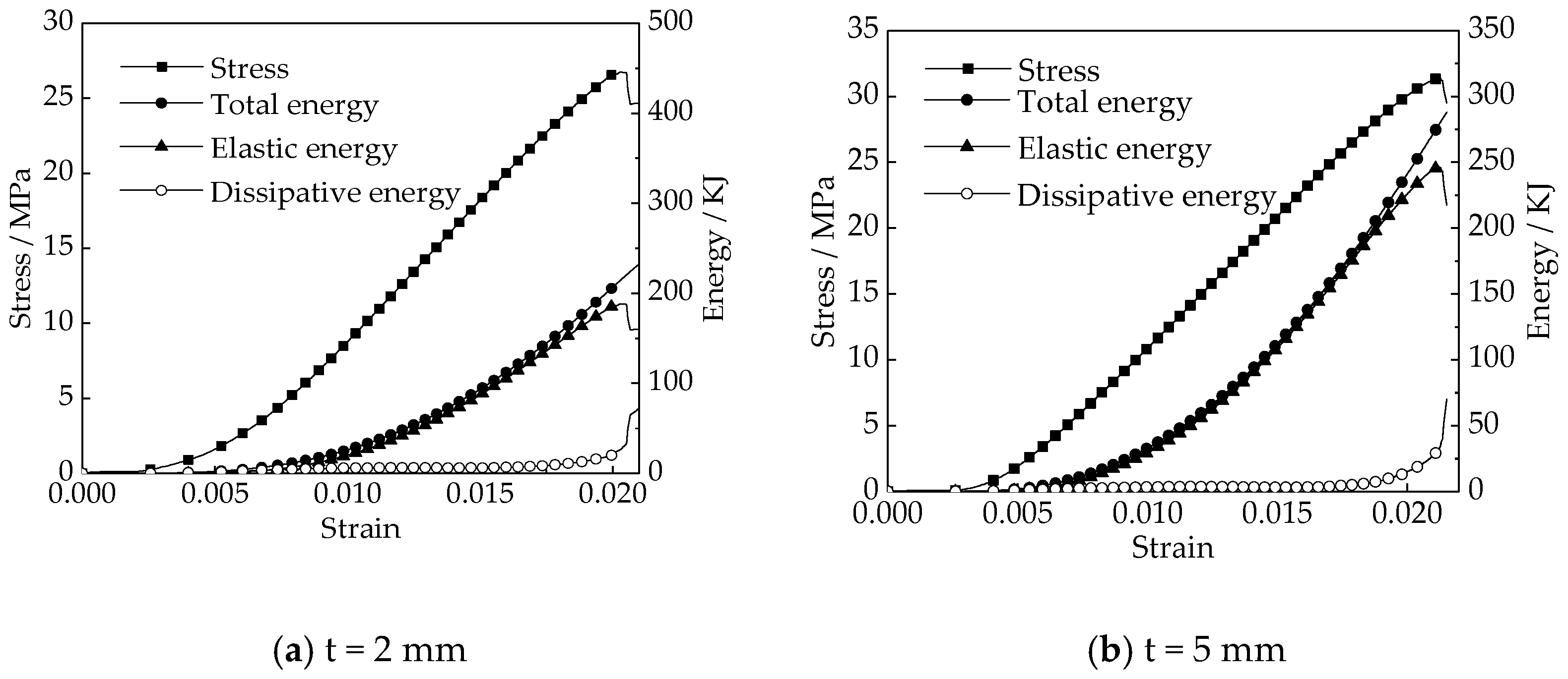
As shown in Figure 14, in the uniaxial compression process, when β = 0° and t = 5 mm, two obvious stress drops appeared during the process of adding stress. Correspondingly, when t = 2 mm, the proportion of energy dissipated in the total energy during compression is larger. When the sample was compressed, the larger the volume ratio of the slurry was, the more obvious the deformation disharmony was, and the interface between the slurry and the rock was more prone to crack and tensile failure. When the slurry and the rock were separated, the rock and the slurry could continue to bear the pressure independently. After the peak stress of the two samples, the elastic energy decreased rapidly and the dissipated energy increased rapidly, which indicated that the brittle failure occurred finally.
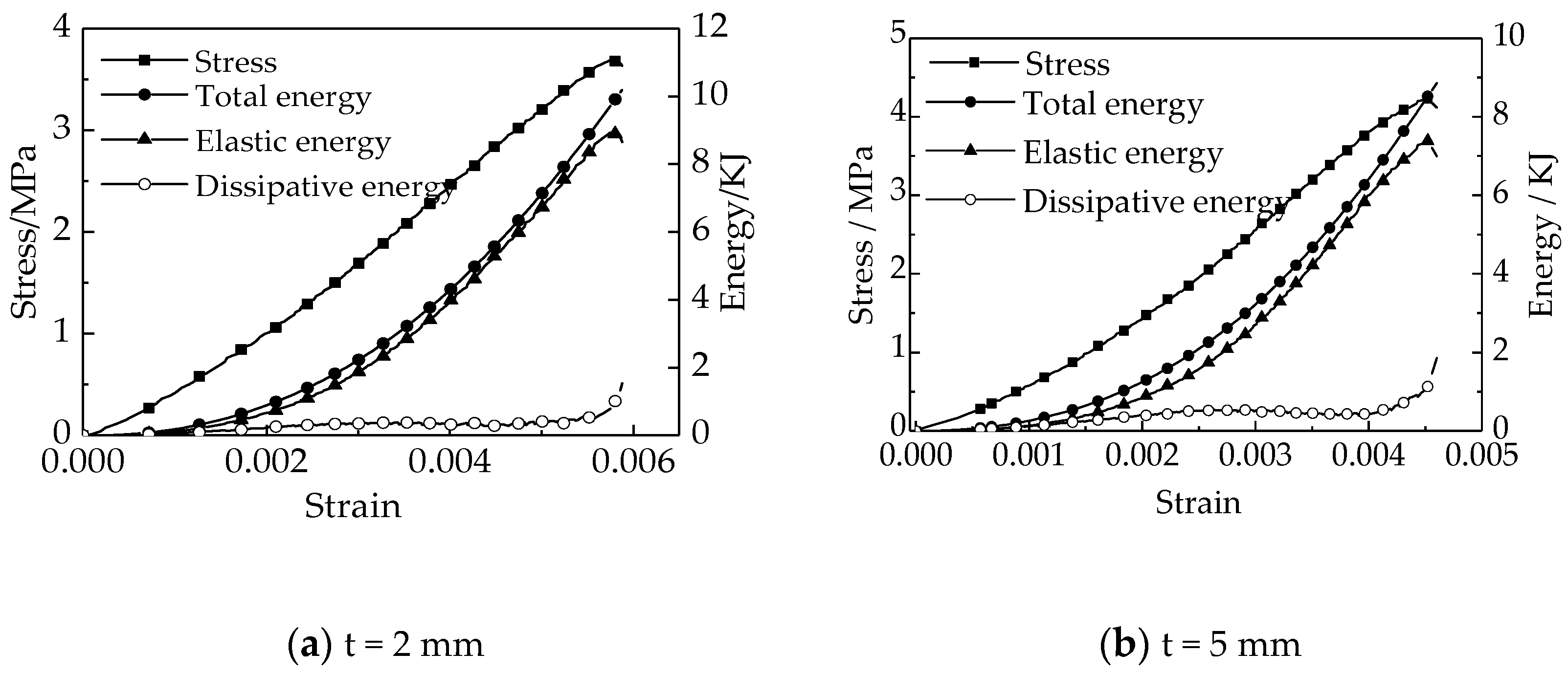
As shown in Figure 15, when the angle between the crack and the load direction was 30°, the stress-strain curve was smooth and nearly linear before peak stress. At the same time, the compressive strength and energy storage capacity of the sample were not significantly related to the thickness of the slurry.
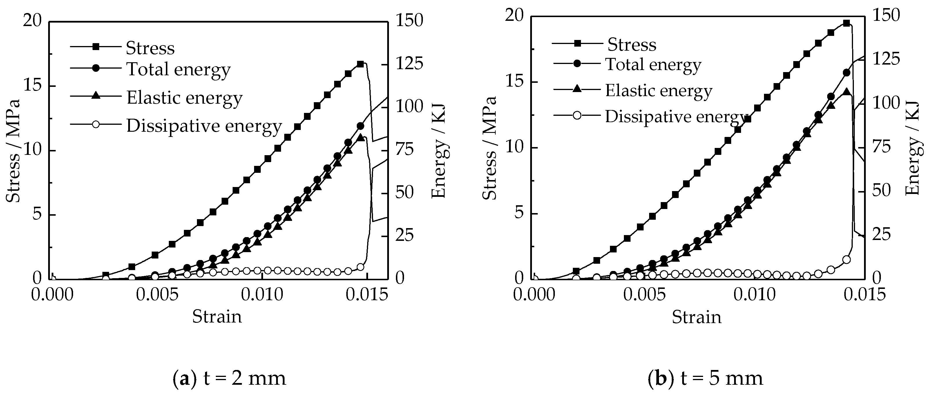
As shown in Figure 16, Figure 17 and Figure 18, when β ≥ 45° and t = 5 mm, the peak strength and energy storage capacity of the grouted rock were greater than that with the thickness of 2 mm. With the increase of the angle between load direction and crack from 45° to 90°, the peak strength and energy storage capacity of the grouted rock increased with the same crack thickness, and the reinforcement effect of slurry on the whole sample was obvious.
In the process of uniaxial compression, from the view of energy input, accumulation, dissipation, and release, the damage and fracture evolution process of grouted rock is similar to that of intact rock sample. The damage and fracture evolution process of grouted rock sample in uniaxial compression process can be divided into four stages: (1) Initial damage stage. In this stage, the damage degree of the rock is small, and some energy will be dissipated by the fracture closure in the sample and the rock-slurry interface. (2) Damage stable development stage. With the increase of input energy, the elastic energy increases linearly. This stage is the major stage of energy storage. At the same time, the dissipative energy increases gradually as new cracks are initiated and developed in the samples. (3) Damage acceleration stage. At this stage, the dissipation energy begins to increase rapidly, the internal cracks begin to develop rapidly. (4) Destruction stage. At this stage, the dissipated energy suddenly increases, the crack penetrates the samples, and the elastic energy suddenly decreases, which means that the strength of the samples suddenly decreases until it fails.
However, in the damage stable development stage and damage acceleration stage, the development of cracks in the grouted rock is different from that in the natural intact rock mass. In this test, because the strength of the original rock is less than that of the slurry, and the microstructure of the slurry is dense, the initial cracks mostly occur in the original rock. When the fracture develops from the original rock part to the slurry part, more energy is needed, and the energy needed for the development of fractures in the slurry is more than that in the original rock body. Therefore, when the failure mode of grouted rock is not controlled by the interface of the rock and slurry, the higher the proportion of slurry volume, the greater the energy storage capacity of grouted rock.
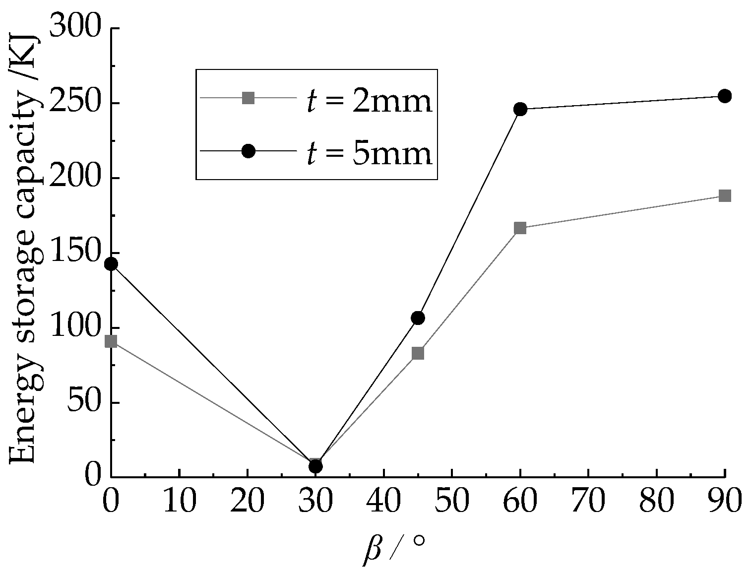
As shown in Figure 19, the energy storage limit of the grouted rock changes in a U-shape with the increase of the angle between the load direction and the crack. When β = 30°, there is no significant relationship between the energy storage limit and the slurry thickness. The reason is that the failure of the sample is controlled by the interface of rock and slurry. In addition, when the thickness of the slurry is 5 mm, the energy limit value is greater than that with the slurry thickness of 2 mm.
4. Discussion
(1) The grout properties will inevitably affect the reinforcement. The grout properties that affect the mechanical properties of grouted rock mainly include grout strength and the cohesion between the grout and the original rock. Different proportions of raw materials will lead to different strength. In this paper, the mechanical strength of the slurry is greater than that of the original rock. When the reinforced body does not slide along the magmatic rock interface under pressure, the higher the strength of the grout, the better the reinforcement effect. However, the cohesion of the interface between grout and rock is far less than that of the original rock itself, which is also the deficiency of the grouting material commonly used in underground engineering. The cohesion between the grout-rock interface depends on the geometric form of the crack and the chemical reaction between the grout and the original rock, and the chemical reaction is the main factor. In actual engineering, the geometric form of the crack cannot be changed, but different grouting materials can be tried from the perspective of improving the chemical bond between the grout and the original rock to improve the cohesion between the grout-rock interface.
(2) It can be seen from this article that when the angle between the principal stress direction and the crack is within a certain range, the grouting reinforcement effect is not obvious, such as the case where β was 30° in this article. During the excavation of underground space, the direction of principal stress will be deflected, and the direction of principal stress and cracks will be recombined. After grouting reinforcement, the weak position can be judged according to the conclusion of this paper. Due to the limitation of grouting’s reinforcement effect, for the weak position after reinforcement, other reinforcement methods such as bolt or anchor cable can be combined.
(3) In actual construction, there is no guarantee that the grout will completely fill the cracks. The spread of grout depends on the grouting construction parameters, including grouting pressure, grouting hole layout, etc. The grouting effect is not as good as the results obtained in the laboratory, so in actual engineering, the reduction of the effect of grouting reinforcement should be considered.
5. Conclusions
In this paper, through uniaxial compression test of grouted rock samples with bi-directional penetration cracks, the failure mode, uniaxial compressive strength, and bear energy capacity of grouted rock were analyzed, and the following conclusions were obtained:
(1) The inclination angle between the crack and the load direction determines the failure mode of grouted rock. With the increase of the angle from 0° to 90°, the failure mode of reinforced body changes from compression shear failure to sliding failure along the slurry-rock interface, and then to compression shear failure.
(2) With the increase of the inclination angle from 0° to 90°, the uniaxial compressive strength decreased and then increased again. When the inclination angle was 30°, the uniaxial compressive strength just depended on the slurry-rock interface, and had nothing to do with the thickness of the grout.
(3) When the inclination angle was not 30°, the greater the slurry body thickness was, the greater the uniaxial compressive strength and ultimate energy storage capacity were.
Author Contributions
Conceptualization, H.F. and X.Z. (Xuemin Zhang); methodology, X.Z. (Xuemin Zhang); validation, X.O. and C.Z.; data curation, H.F., X.C., and X.Z. (Xianshun Zhou); writing—original draft preparation, H.F., X.C., and X.Z. (Xianshun Zhou); writing—review and editing, X.Z. (Xuemin Zhang); supervision, X.Z. (Xuemin Zhang); project administration, H.F.; funding acquisition, X.Z. (Xuemin Zhang). All authors have read and agreed to the published version of the manuscript.
Funding
This research was funded by National Natural Science Foundation of China, grant number 51978671.
Institutional Review Board Statement
Not applicable.
Informed Consent Statement
Informed consent was obtained from all subjects involved in the study.
Data Availability Statement
The data presented in this study are available on request from the corresponding author.
Conflicts of Interest
The authors declare no conflict of interest.
References
- Cambefort, H. Principles and applications of grouting. Q. J. Eng. Geol. Hydrogeol. 1977, 10, 57–95. [Google Scholar] [CrossRef]
- Turk, N.; Dearman, W.R. Assessment of grouting efficiency in a rock mass in terms of seismic velocities. Bull. Int. Assoc. Eng. Geol. 1987, 36, 101–108. [Google Scholar] [CrossRef]
- Jorne, F.; Henriques, F.M.A. Evaluation of the grout injectability and types of resistance to grout flow. Constr. Build. Mater. 2016, 122, 171–183. [Google Scholar] [CrossRef]
- Mirza, J.; Mirza, M.S.; Roy, V.; Saleh, K. Basic rheological and mechanical properties of high-volume fly ash grouts. Constr. Build. Mater. 2002, 16, 353–363. [Google Scholar] [CrossRef]
- Ibragimov, M.N. Soil stabilization with cement grouts. Soil Mech. Found. Eng. 2005, 42, 67–72. [Google Scholar] [CrossRef]
- Güllü, H.; Cevik, A.; Al-Ezzi, K.M.A.; Gülsan, M.E. On the rheology of using geopolymer for grouting: A comparative study with cement-based grout included fly ash and cold bonded fly ash. Constr. Build. Mater. 2019, 196, 594–610. [Google Scholar] [CrossRef]
- Kim, Y.U.; Park, J.; Chun, Y.W.; Zhang, G.M. Evaluation and prediction of physical properties of pressure grouting using laboratory testing and elastic wave velocity. KSCE J. Civ. Eng. 2013, 17, 364–367. [Google Scholar] [CrossRef]
- Salimian, M.H.; Baghbanan, A.; Hashemolhosseini, H.; Dehghanipoodeh, M.; Norouzi, S. Effect of grouting on shear behavior of rock joint. Int. J. Rock Mech. Min. 2017, 98, 159–166. [Google Scholar] [CrossRef]
- Liu, Y. Experimental study on the shear behavior of regular sandstone joints filled with cement grout. Rock Mech. Rocr. Eng. 2017, 50, 1321–1336. [Google Scholar] [CrossRef]
- Ma, H.; Liu, Q. Prediction of the Peak Shear Strength of Sandstone and Mudstone Joints Infilled with High Water-Cement Ratio Grouts. Rock Mech. Rock Eng. 2017, 50, 2021–2037. [Google Scholar] [CrossRef]
- Lee, J.S.; Bang, C.S.; Mok, Y.J.; Joh, S.H. Numerical and experimental analysis of penetration grouting in jointed rock masses. Int. J. Rock Mech. Min. Sci. 2000, 37, 1027–1037. [Google Scholar] [CrossRef]
- Sun, F.; She, C.; Wan, L. A peak shear strength model for cement filled rock joint. Chin. J. Rock Mech. Eng. 2014, 33, 2481–2489. [Google Scholar]
- Han, L.; Zong, Y.; Han, G. Study on Shear Properties of Rock Structural Plane by Grouting Reinforcement. Rock Soil Mech. 2011, 32, 2570–2622. [Google Scholar]
- Dong, W.; Wu, Z.; Zhou, X. Fracture Mechanisms of Rock-Concrete Interface: Experimental and Numerical. J. Eng. Mech. 2016, 142, 04016040. [Google Scholar] [CrossRef] [Green Version]
- Saiang, D.; Malmgren, L.; Nordlund, E. Laboratory tests on shotcrete-rock joints in direct shear, tension and compression. Rock Mech. Rock Eng. 2005, 38, 275–297. [Google Scholar] [CrossRef]
- Tian, H.M.; Chen, W.Z.; Yang, D.S.; Yang, J.P. Experimental and Numerical Analysis of the Shear Behaviour of Cemented Concrete-Rock Joints. Rock Mech. Rock Eng. 2014, 48, 213–222. [Google Scholar] [CrossRef]
- Le, H.; Sun, S.; Kulatilake, P.H.S.W.; Wei, J. Effect of Grout on Mechanical Properties and Cracking Behavior of Rock-Like Specimens Containing a Single Flaw under Uniaxial Compression. Int. J. Geomech. 2018, 18, 04018129. [Google Scholar] [CrossRef]
- Le, H.; Sun, S.; Thu, F.; Fan, H. Experimental Investigation on Failure Modes and Mechanical Properties of Rock-Like Specimens with a Grout-Infilled Flaw under Triaxial Compression. Shock Vib. 2019, 2019. [Google Scholar] [CrossRef]
- Le, H.; Sun, S.; Kulatilake, P.H.S.W.; Wei, J. Effect of grout in-filling, flaw thickness and inclination angle on strength and failure pattern of rock-like specimens with single flaw. Arab. J. Geosci. 2019, 12, 12. [Google Scholar] [CrossRef]
- Miao, S.; Pan, P.; Wu, Z.; Li, S.; Zhao, S. Fracture analysis of sandstone with a single filled flaw under uniaxial compression. Eng. Fract. Mech. 2018, 204, 319–343. [Google Scholar] [CrossRef]
- Zhao, Z.; Zhou, D. Mechanical properties and failure modes of rock samples with grout-infilled flaws: A particle mechanics modeling. J. Nat. Gas Sci. Eng. 2016, 34, 702–715. [Google Scholar] [CrossRef]
- Wang, Y.; Zhang, H.; Lin, H.; Zhao, Y.; Li, X.; Liu, Y. Mechanical behavior and failure analysis of fracture-filled gneissic granite. Theor. Appl. Fract. Mech. 2020, 108, 102674. [Google Scholar] [CrossRef]
- Zhong, Z.; Deng, R.; Zhang, J.; Hu, X. Fracture properties of jointed rock infilled with mortar under uniaxial compression. Eng. Fract. Mech. 2020, 228, 106822. [Google Scholar] [CrossRef]
Figure 1.
Samples with unidirectional crack. (a) single crack [17,18,19], (b) double cracks [21], (c) irregular crack [22].

Figure 2.
Samples with bidirectional crack [23].
Figure 2.
Samples with bidirectional crack [23].

Figure 3.
The production process of the standard sample.

Figure 4.
Control method of crack width.

Figure 5.
Sample production flow chart.

Figure 6.
The schematic diagram of the specimen.

Figure 7.
Samples with prefabricated cracks.

Figure 8.
Actual grouted rock samples (β = 45°).

Figure 9.
Failure mode of the samples.

Figure 10.
Grout crushing diagram.

Figure 11.
Stress-strain curve of test samples.

Figure 12.
Change of strength and elastic modulus.

Figure 13.
Energy composition diagram.

Figure 14.
Energy change diagram.

Figure 15.
Energy change diagram.

Figure 16.
Energy change diagram.

Figure 17.
Energy change diagram.

Figure 18.
Energy change diagram.

Figure 19.
Energy storage change of reinforcement.


Table 1.
Mechanical parameters of samples.
| Crack Width/mm | β/° | Strength/MPa | Peak Strain/% | Elastic Modulus/GPa |
|---|---|---|---|---|
| 2 | 0 | 24.42 | 1.61 | 2.09 |
| 30 | 3.69 | 0.59 | 0.76 | |
| 45 | 16.80 | 1.49 | 1.70 | |
| 60 | 26.74 | 2.03 | 1.94 | |
| 90 | 27.12 | 2.04 | 2.34 | |
| 5 | 0 | 25.74 | 1.77 | 2.42 |
| 30 | 4.22 | 0.45 | 1.21 | |
| 45 | 19.48 | 1.42 | 1.71 | |
| 60 | 31.37 | 2.09 | 2.01 | |
| 90 | 35.11 | 2.13 | 2.42 |
Publisher’s Note: MDPI stays neutral with regard to jurisdictional claims in published maps and institutional affiliations. |
© 2021 by the authors. Licensee MDPI, Basel, Switzerland. This article is an open access article distributed under the terms and conditions of the Creative Commons Attribution (CC BY) license (http://creativecommons.org/licenses/by/4.0/).
Share and Cite
MDPI and ACS Style
Feng, H.; Zhang, X.; Zhou, X.; Ou, X.; Zhang, C.; Chen, X. Experimental Study on the Compression Behavior of Grouted Rock with Bi-Directional Penetrating Crack. Appl. Sci. 2021, 11, 537. https://doi.org/10.3390/app11020537
AMA Style
Feng H, Zhang X, Zhou X, Ou X, Zhang C, Chen X. Experimental Study on the Compression Behavior of Grouted Rock with Bi-Directional Penetrating Crack. Applied Sciences. 2021; 11(2):537. https://doi.org/10.3390/app11020537
Chicago/Turabian StyleFeng, Han, Xuemin Zhang, Xianshun Zhou, Xuefeng Ou, Cong Zhang, and Xinlei Chen. 2021. "Experimental Study on the Compression Behavior of Grouted Rock with Bi-Directional Penetrating Crack" Applied Sciences 11, no. 2: 537. https://doi.org/10.3390/app11020537
Note that from the first issue of 2016, this journal uses article numbers instead of page numbers. See further details here.