Repeatability and Reproducibility Assessment of a PolyJet Technology Using X-ray Computed Tomography


Faculty of Mechanical Engineering and Naval Architecture, University of Zagreb, Ivana Lucica 5, 10000 Zagreb, Croatia
*
Authors to whom correspondence should be addressed.
Appl. Sci. 2020, 10(20), 7040; https://doi.org/10.3390/app10207040
Submission received: 10 September 2020
/
Revised: 6 October 2020
/
Accepted: 7 October 2020
/
Published: 10 October 2020
(This article belongs to the Special Issue Progress in 3D Printing of Materials)
Abstract
:Featured Application
From the beginning of the use of additive technology in small series, a major problem has been the repeatability of the results. This repeatability is most evident in different dimensions of the finished product. Additionally, depending on the time of printing during the year, there are large differences in the same products. Such a problem is particularly apparent in the processes of additive production in which the material is applied in the liquid form. Such repeatability is, of course, a big problem for the industry which produces small series (e.g., designers). The results from this paper can be applied to processes in additive production that belong to the group of material jetting, but also to other processes where the input material is in the form of liquid, or where acrylates, epoxy resins, etc., are used. PolyJet consistently produces parts within ±100 μm, at a 95% confidence interval. Accuracy and repeatability in the x and y axis are significantly better than in the z axis. Form errors (i.e., cylindricity) are larger than positional or dimensional errors. Holes with diameters less than 0.75 mm cannot be reliably produced using PolyJet.
Abstract
From the very start of their use until today, processes in Additive Manufacturing (AM) have found a way to grow from prototype production to individual and small-series production. Improvements in machinery, materials and other challenges in AM development have improved product quality, its mechanical properties and dimensional accuracy. Research in the field of dimensional accuracy must be focused on achieving better tolerances. From the beginning of AM, there has been a big issue in assuring dimensional repeatability and reproducibility of a part being printed over the course of several days. In order to examine that, a test plate was designed and built repeatedly with PolyJet technology over the course of several weeks. Measurements of dimensional accuracy and shape deviations of several typical features were carried out using X-ray Computed Tomography. Measurement results were analysed and presented in order to indicate the repeatability and reproducibility of PolyJet AM technology. Results show that PolyJet technology consistently produces parts within ±100 μm, at a 95% confidence interval, under reproducibility conditions of over a 1-month period. Accuracy for measurands (distance) in the x and y axis was significantly better than it was for the z axis which was from 56 to 197 µm, i.e., in the x and y axis, it was from −8 to 76 µm. Shape errors (i.e., cylindricity) were larger than positional or dimensional errors; this can be attributed to relatively large surface roughness and small feature sizes on the test plate that was used.
1. Introduction
Numerous pieces of research in the field of AM have resulted in a large number of manufacturing limitations, as well as in the design guidelines. Through the understanding of all manufacturing limitations, design rules can be defined to achieve better product quality and dimensional accuracy [1,2,3,4]. Design rules are also used for comparing the dimensional accuracy of the product printed with different AM processes [5].
The minimum feature size and tolerances of AM processes depends on the smallest parts that can be printed. This is connected to dimensional accuracy and repeatability of the machine in all AM processes [6].
The design, production, and measurement of a standardised test plate (test artefacts) allow the assessment of the performance of AM machines and processes [7].
Every AM process has a limit on the smallest feature that it can print. Kim and Oh [8] found out that this depends on the used process and machine (size of nozzle, beam diameter), materials (e.g., particle size), resolution in the x, y and z direction, layer thickness, shape of the part, feature direction (debossed or embossed), part orientation in the working chamber of the machine, etc.
There are a large number of additive manufacturing processes. However, in this paper, we deal with the material jetting process, which uses photopolymers. Yap et al. [5] and Meisel [9] expanded the aforementioned limits to PolyJet and added surface finish types (matte and glossy). In the PolyJet process, layer thicknesses of 16 and 32 micrometres can be printed and the machine has a resolution of 42 micrometres in the x and y directions.
In AM, test plates are used not only to compare the strengths and weaknesses of the parts but also to measure and compare accuracy, surface finish, repeatability and resolution of the geometrical features of the parts produced. The test plate helps in identifying the “highest standards of excellence” for different products/processes so that the subsequent improvements necessary to achieve those standards can be made [10].
The test plate design has been proposed by many authors throughout the evolution of the products made by AM. The test plate must include rectangular and circular features to find out the minimum part/feature size. The most important advantage of PolyJet is high resolution, so authors in literature [7,9] suggested circle diameter from 0.1 mm to 1 mm, rectangle width from 0.1 mm to 1 mm and rectangle length from 0.3 mm to 3 mm.
In some literature references, it can be found that the smallest test features of the AM test plate were 0.25 mm thin walls (for both polymer-based and metal-based AM processes), 0.2 mm diameter holes and bosses in polymer-based AM processes, and 0.5 mm diameter holes and bosses in metal-based AM processes [6,11].
Moylan et al. [12,13] also suggested some rules for test artefacts for the additive manufacturing standard accuracy test. These rules are: test plate must test machine performance near the end of the platform as well as in the centre, have features of different sizes, as well as have holes and bosses. Many of the features should represent real-life parts like thin walls, flat surfaces, holes, and more. Additionally, the plate should be built as fast as possible with small amounts of material and be easy to measure. Scaravetti et al. [14] added that test plate needs to have simple geometrical shapes, without post-treatment (e.g., without support structures), and allow repeatability measurements.
Authors Beltrán et al. [15] concluded that the product orientation and size affect the quality of the products printed with PolyJet, whereas the location of the products in the working chamber has no influence.
Cooke and Soons [16] and Scaravetti et al. [14] tested the dimensional accuracy of equal parts made by different AM processes as well as when the parts were made by the same process but with different printers. In our previous research, we compared different procedures for the making of identical test plates, compared the printed part with the Computer aided design (CAD) model and found the best measurement method for some of the small details in products [17].
In this paper, we present the results of dimensional measurements of products built on the same machine under repeatability and reproducibility conditions. The goal of the research was to verify dimensional accuracy for the product built with PolyJet process using CT scanning, but also to investigate the repeatability and reproducibility of products. A similar study was carried out by the author Shah et al. [18] who investigated the procedures of selective laser sintering, fused deposition modelling and stereolithography.
X-ray Computed Tomography (CT) has been increasingly used in industry for dimensional quality control. CT, compared to traditional measuring methods, enables dimensional analysis in a non-contact and non-destructive way on a wide variety of components for exterior and interior (hidden) features. Recent developments of CT machines, which include (sub)micrometre focal spot X-ray sources and improved software algorithms for reconstruction of measured volume, resulted in measurement uncertainties comparable to classical CMM (coordinate measuring machine) measurements. The capabilities of the CT machine used in this work have been extensively researched by authors Stolfi et al. [19] and Kraemer et al. [20], with typical standard measurement uncertainties (k = 1) ranging from 5 µm to 10 µm for polymer parts and various measurand types (cylinder diameters, axial distances, plane to plane distance). Our own research [21], performed on a multimaterial polymer part with the same CT machine used in this work, shows standard measurement uncertainties between 3 µm and 10 µm, depending on the selected measurands. When these results are compared with the expected accuracy of various additive manufacturing technologies, it can be reasonably expected that CT measurements will have sufficient resolution and accuracy to reliably measure AM parts. However, the surface roughness of AM parts is typically large, which can influence the surface determination of measurands in CT scans. This effect must be corrected through the use of advanced surface determination algorithms (locally adaptive thresholding) and taken into account for measurement uncertainty [22,23].
There are few repeatability studies on metal products produced by additive manufacturing. Thus, for example, the authors Kouach and Tollander [24] tested the repeatability on vibrations in aluminium parts and found that selective laser melting (SLM) has high repeatability and repeatability is higher in the horizontally printed product compared to vertically printed products. This was also concluded by the authors Prashanth et al. [25]—SLM can be used to produce parts with reproducible properties, provided the powder quality and the processing parameters do not change.
2. PolyJet Technology
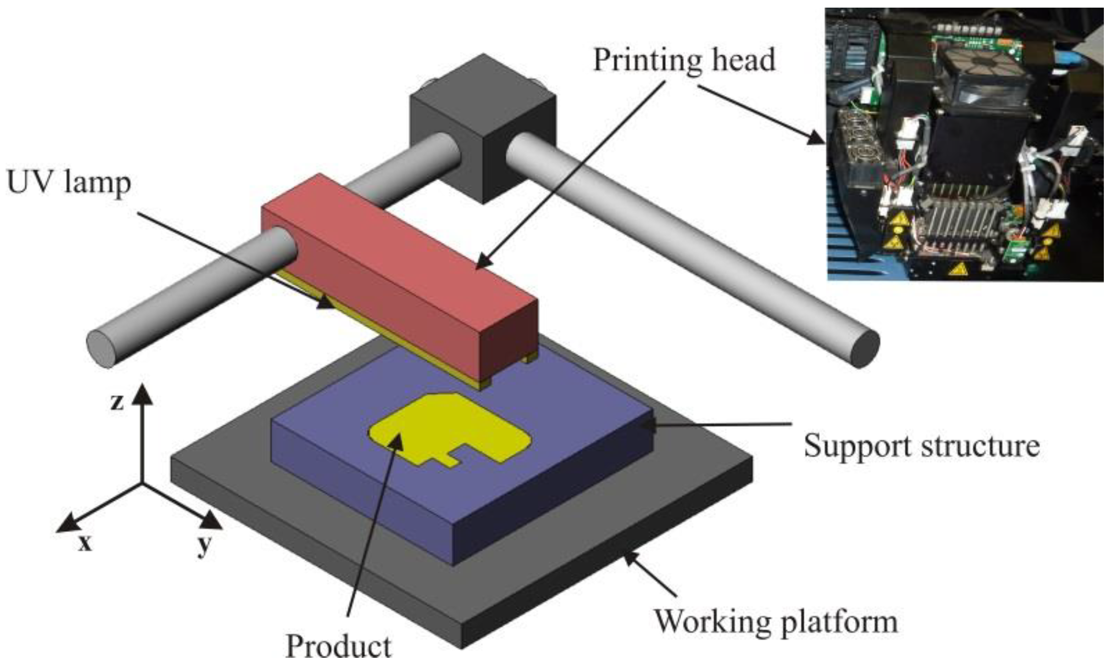
Before designing the test plate for analysing repeatability and reproducibility, it is important to understand how the PolyJet process works. The company Objet Geometries developed the PolyJet (nozzle-network) technique in 2000 [26] (Figure 1).
The network of nozzles moves in the direction of x and y axes and prints a layer of photosensitive polymeric material of 16 μm thickness. In each layer, polymerization takes place under the influence of UV light, immediately after printing, forming a completely cured product, with no need for second curing. Two different materials are used for the model and for the support. After the completion of the first layer, the working platform lowers for the thickness of the next layer. Once the product is produced, the support is removed by water or manually [26,28,29].
PolyJet technology belongs to the material jetting procedures according to the ASTM F42:2010 standard. The material in a liquid state solidifies through a process of photopolymerization, also known as photo-curing. Photopolymerization is based on using monomers/oligomers in a liquid state that can be cured/photopolymerized upon exposure to a light source of a specific wavelength. Photoinitiators are needed to convert photolytic energy into the reactive species (radical or cation) which can drive the chain growth via radical or cation mechanism. Typically photoinitiators with high molar extinction coefficients at short wavelength (mostly UV < 400 nm) are used to initiate the photochemical reaction. Materials that are used in PolyJet are acrylates that need a radical method for polymerization. In the process, photoinitiators convert light energy into chemical energy by forming free radicals upon UV exposure.
Vero material photopolymers that were used in this experiment are generally composed of a binder, monomers (10–40%) and photoinitiators (50–80%). PY-GC/MS (pyrolysis) results proved that it is a composite material, i.e., a monofunctional polymer based on acrylic acid, styrene tetramer with benzophenone-based binders, phenolic antioxidants and organophosphorus oxides [30].
Liquid resin is heated from 30–70 °C to achieve optimal viscosity for printing [31,32]. The advantages of the PolyJet technology are: high quality of the product, high precision (very thin layers), high surface quality, possibility of producing small and thin walls and details, usage in offices, and fast production. Additionally, no second curing is needed and it is possible to mix FullCure materials which allow achieving of different geometries, mechanical properties and colours [27,33,34].
It must be noted that the surfaces of the finished product can be matte and glossy. In a glossy setting, the support material is added only when it is structurally required (i.e., for overhangs), so surfaces not in direct contact with support will have a glossy finish, while supported areas will be matte. In the matte setting, a thin layer of support material is added around the whole part, regardless of orientation or structural requirements. This way, all surfaces have a matte finish [35].
As the material is sensitive to light, properties of the products can change over time.
The first few layers are made of just supporting structure so the product can be easily and without damage removed from the platform when finished. The support material is injected from nozzles located on the printer head. Support (gel-like material) is dissolvable material that can be removed after printing using pressurized water (water jetting) or solvents (caustic soda and sodium metasilicate), by immersion in an ultrasonic bath or manually [33,35].
PolyJet technology allows the producers and engineers to shorten production cycles and lead-times for launching the product on the market. It is used in the automotive industry, electronics, in the production of toys, footwear, consumer goods, and in the production of jewellery [33].
3. Design of Test Plate
In literature [5,36] and in many more studies, authors investigated how processing parameters (for example, layer thickness, surface finish, and build location) influence dimensional accuracy, surface roughness and mechanical properties. A thin wall test plate (0.2–1 mm in intervals of every 0.1 mm) was suggested, but for the PolyJet process, the distance between these thin walls is equally important as wall thickness itself. In our previous experiment, the measurement results revealed limitations of the Polyjet process when printing small raised and recessed L structures. It was determined that when the distance between structures is larger than 0.4 mm, the structures are printed in accordance with the CAD model. However, when the distance between structures is at the level of 0.3 mm or less, the PolyJet machine fails to print structures in accordance with the CAD model, i.e., structures are then printed only partially [17,37]. Our study is aimed to investigate the dimensional stability of a part during printing in the same series in intervals. Due to that, the test plate was designed with fewer features than other reviewed designs.
From our previous research, some limitations of the machine itself were identified. Holes with diameters smaller than 0.5 mm cannot be printed, either horizontally or vertically. Even larger holes, such as 1 mm in diameter, are not circular and deviations exist. L raised profiles with a spacing of less than 0.5 mm merge together, and PolyJet also cannot make tapered cone tips [37].
All test plates were printed in the same orientation, according to results stated in literature by Beltrán et al. [15] to maximally avoid the influence of the machine and specificity of the process. In a study by authors Kechagias et al. [38], it was found out that build styles (surface finish types and layer thickness) influence dimensional accuracy. Surface finish types can be matte and glossy. Better dimensional accuracy is obtained with matte surface and printing along the z axis, but printing with glossy finish type reduces material cost and the subsequent removal of the support [5]. For this reason, it was decided that the matte finish type will be used only for the holes in the XZ plane, and everything else will be glossy finish type.
A big limitation of PolyJet technology is the likelihood of destroying the small parts that the machine can print while cleaning them with water.
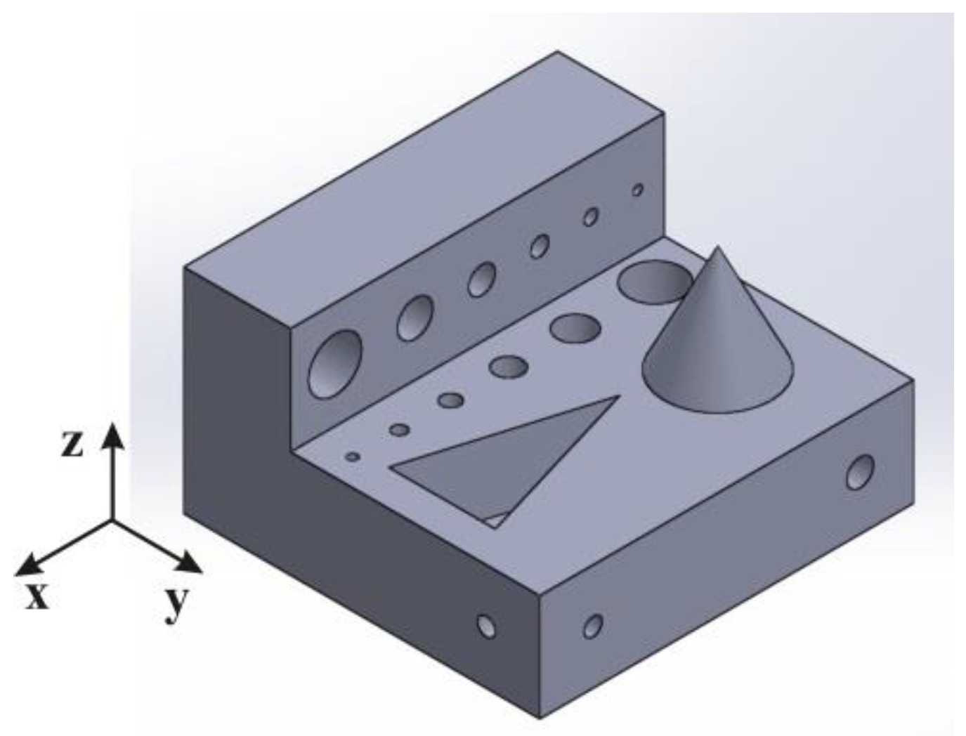
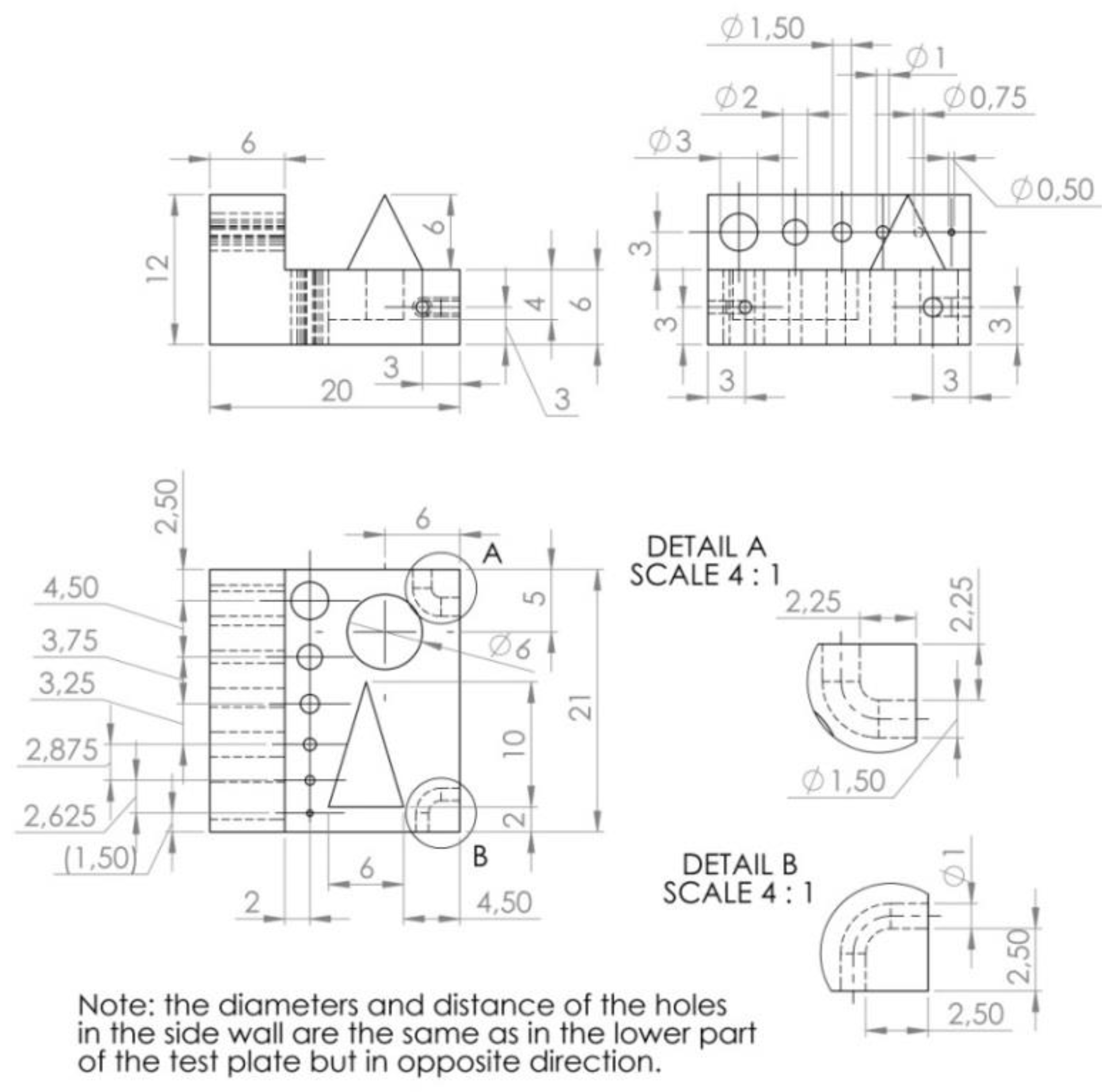
According to some of the rules described in the introduction and our pre-test, the test plate design is shown in Figure 2 and Figure 3. The hole diameters in plane XY and XZ are 3, 2, 1.5, 1, 0.75 and 0.5 mm. The distance between the beginning of each hole is 2 mm. The channel diameter is 1.5 mm on one side of the plate and 1.0 mm on the other side. The base diameter and height of a cone are both 6 mm.
In order to test the repeatability of the results, a plan for printing the test plates was made so that three identical test plates were made successively in each cycle. Test plates were made of VeroBlack material on machine Objet Connex 350 with resolution in of 600 dpi x and y axis and 1600 dpi in z-axis More information about the printer can be found in reference [39]. Slicing software and preparation of the model was done in Objet Studio which is the default of the 3D printer itself. Material requirements for three plates were 20 g of VeroBlack material and 10 g of supporting structures/material SUP 705. The support material was removed by pressurized water. The production time was 1 h. Test plates were built with a layer thickness of 0.016 mm with glossy surface finish and with position and orientation in the working platform in the left upper corner shown in Figure 4. The temperature of the printing head was 70 °C and printing was performed at room temperature, 22 °C, and humidity 45%.
According to Delgado et al. [40], better repeatability is obtained in the XY plane, compared to the other two orthogonal planes.
After the first set of test plates (No. 1.1, 1.2 and 1.3), another three test plates were printed after one day (No. 2.1, 2.2 and 2.3) and again after two days (No. 3.1, 3.2 and 3.3), i.e., test plates were printed at one-day intervals in the same orientation, using the same materials and parameters. After that, other products with different materials and parameters were printed on the machine. To test reproducibility and dimensional accuracy, after two weeks another set of three test plates (No. 4.1, 4.2 and 4.3) was manufactured and repeated after one day (No. 5.1, 5.2 and 5.3) and after two days (No. 6.1, 6.2 and 6.3). After additional two weeks the last set of test plates was printed (No. 7.1, 7.2 and 7.3). Table 1 shows the print plan of test plates by day and Figure 5 shows the printed test plate.
4. Measurement Results
The schedule of test plates printing was designed to simulate the regular use of printer: the first sets were produced in the same conditions (repeatability), and after the machine was used for printing various other parts, additional groups of test plates were printed in different time intervals (reproducibility).
To verify the accuracy, as well as repeatability and reproducibility, five measurands were selected on two geometrical features: cone and largest cylinder in XZ plane. The largest cylinder hole was chosen because of the pre-test that showed that there are large deviations in cylindricity for small holes. Additionally, since the point of this paper is to find repeatability and reproducibility, it was better to choose as large a diameter as possible. However, because there is a bigger problem in cylindricity when it is not printed in the XY plane, only the top hole in the XZ plane shown in Figure 6 was selected. According to [5], mentioned earlier in the text, this hole was also chosen because all the holes in the XZ plane are made with a supporting structure and according to [5], it gives better dimensional stability. The cone was chosen because of its height and to establish a deviation from its position on the test plate. Only two geometrical features were chosen because of the costs of examining the products with the CT method.
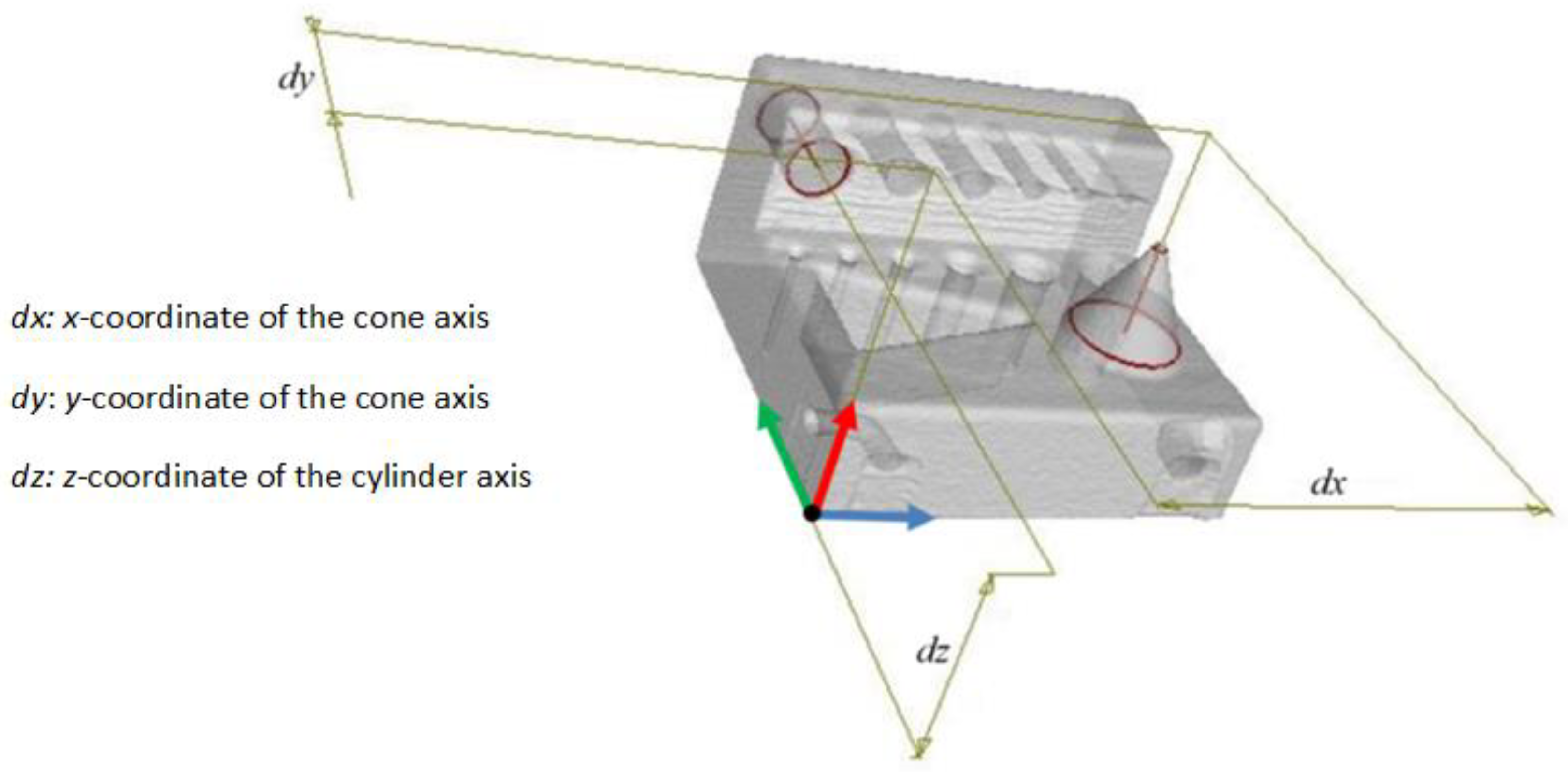
Measurements were carried out using Nikon XT H 225 industrial Computed Tomography (XCT) machine at X-ray energy of 140 kV and X-ray tube current at 150 μA. These parameters were chosen to provide relatively fast scanning times, while still providing sufficiently small focal point size and therefore adequate resolution. The X-ray source used in this experiment links the focal spot size and X-ray power approx. 1 µm per 1 W. In this case, 21 W of X-ray power resulted in a focal spot of approx. 20 μm in diameter and that sets the fundamental hardware resolution limit, prior to software subsampling. Final CT scan data had a voxel size of 64 μm due to the fact that several test plates (each set) were scanned together, in order to ensure similar measurement conditions within each set. Imaging was performed using a 400 mm × 300 mm 14 bit flat panel detector with 127 μm pixel size, exposed at 333 ms. CT data were acquired with 1440 projections with a two-frame averaging. Scanned test plates were reconstructed using Volume Graphics VGStudio Max 3. The coordinate measurement system was aligned with the measured object as presented in Figure 6. Finally, voxel size calibration was performed using an externally calibrated ball-bar standard with a nominal sphere-to-sphere distance of 30 mm. This procedure ensured consistency across all the measured sets of test plates. All measurements in VGStudio Max were made after the Advanced surface determination algorithm was used to define surfaces. Unlike the standard ISO 50 edge determination algorithm, this algorithm uses an adaptive threshold to provide an improved surface definition, reducing the influence of noise and varying material thickness.
In order to check all three axes of the 3D printer, one measurand (distance) per axis was analysed. For the x and y axis, the deviation of the cone axis position from the CAD model was chosen, and for the z axis, the deviation from the position of the axis of the largest cylinder in the XZ plane.
In Table 2, measurement results of deviations in all three axes are given.
5. Discussion
Repeatability and reproducibility have been on the rise in additive manufacturing recently. They depend on the type of technology, production and post-processing, 3D printers and materials [41].
Authors Dowling et al. [41] in their paper on metal additive production concluded that the level of complexity and interconnectedness between parameters (powder morphology, laser characteristics and scan pattern) leads to an improvement of the repeatability and reproducibility of additive manufacturing processes.
Our results indicate that state-of-the-art CT metrology can be recommended as a method of choice for the inspection of polymer AM parts, as achievable accuracy is more than adequate for these components, while measurement time can be kept relatively short (less than 8 min). This coincides with the results of authors Tao et al. who also found that CT scanning is a great method that enables a detailed view of 3D printed parts [42]. Authors Shah et al. tried to establish a comparison in the repeatability of the results in additive manufacturing test plates with CT analysis and coordinate measuring machine (CMM) and their results also support our findings [18]. They concluded that CT is suitable for verification and acceptance of AM parts, conformity and correlation between measurements, visual comparison and deviation of overlap scanned CT data to original CAD models of a variety of AM methods, which provided a means to preliminary analyse the form that is created as well as its differences in feature position [18].
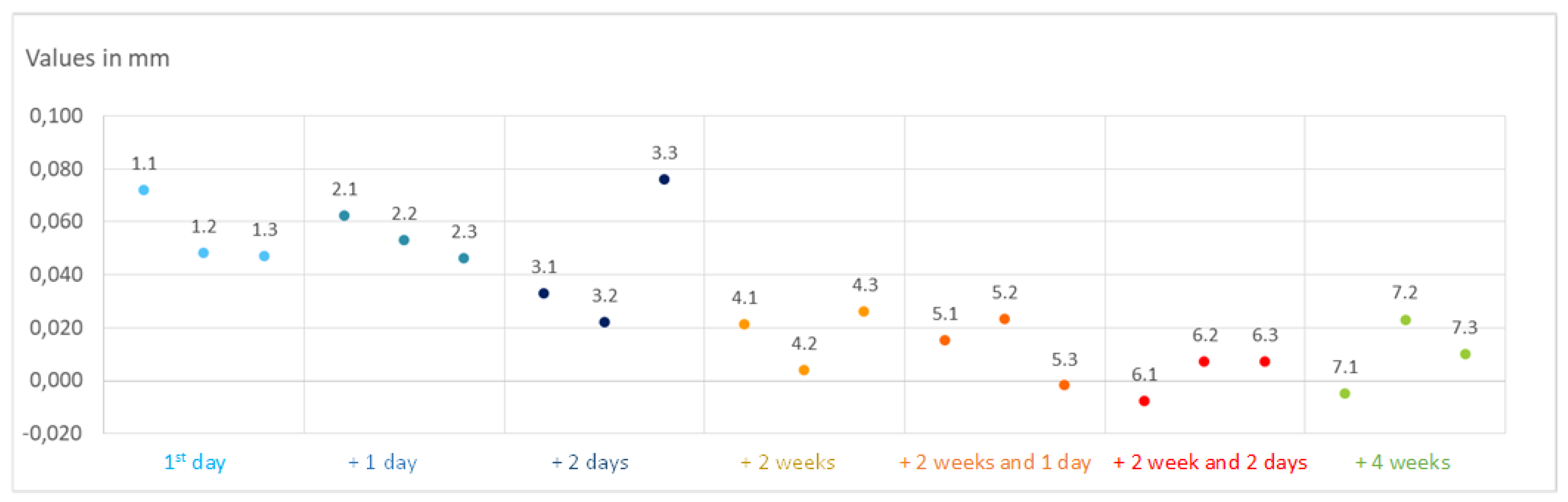
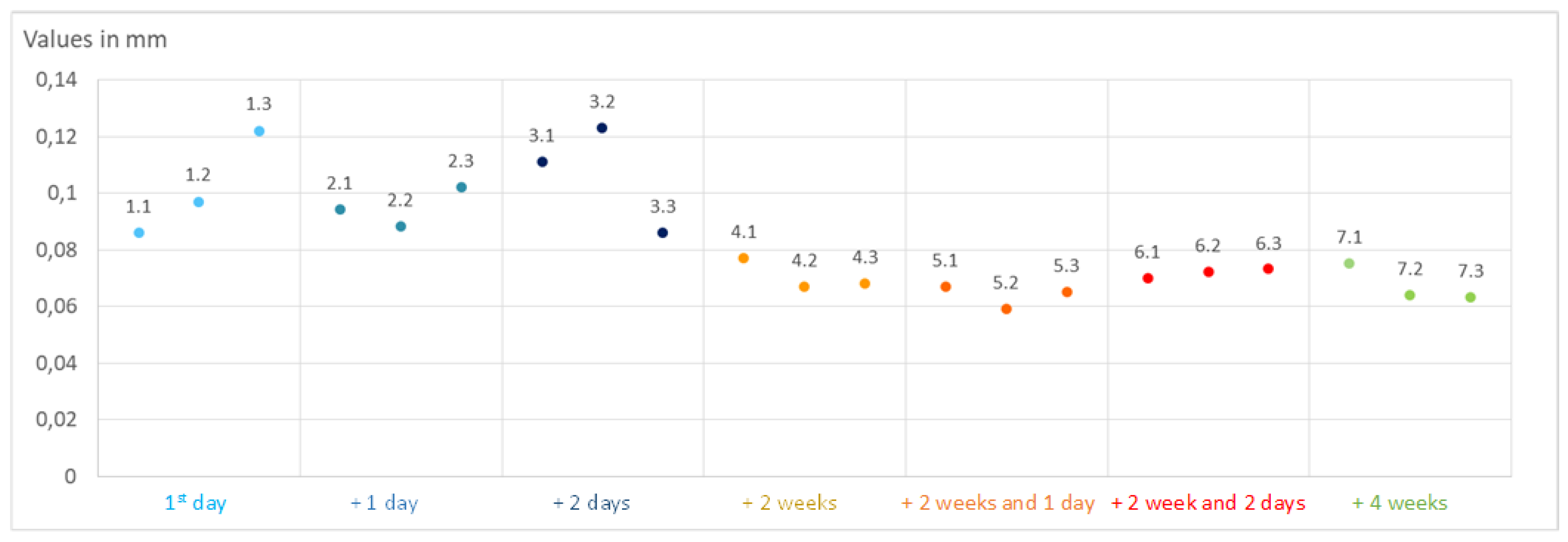
Results of the deviations in the x axis were in the range from −8 µm to 76 µm, and for the y axis, in the range from −10 µm to 100 µm. Deviations in the z axis were grouped around 100 µm, ranging from 56 µm to 197 µm, while cylindricity error ranged from 0.25 mm to 0.50 mm.
In comparison to other test plates, the first three groups (No. 1.x; 2.x and 3.x were x = 1, 2, 3) showed higher values of deviations in the x and y position, as well as in the conicity error.
As was the case with the accuracy, achieved repeatability for measurands (distance) in the x and y axis was better than it was for the z axis (which is also inferred from the mechanical properties in the reference [24]). For seven sets of test plates average value of measurement ranges in the x axis was 26 µm, and 25 µm in the y axis. For the z axis, average value of measurement ranges was 49 µm.
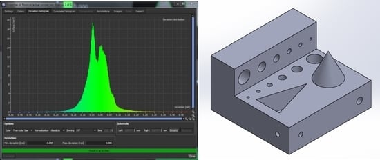
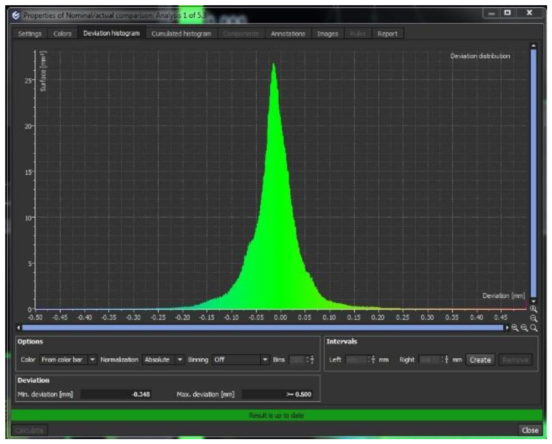
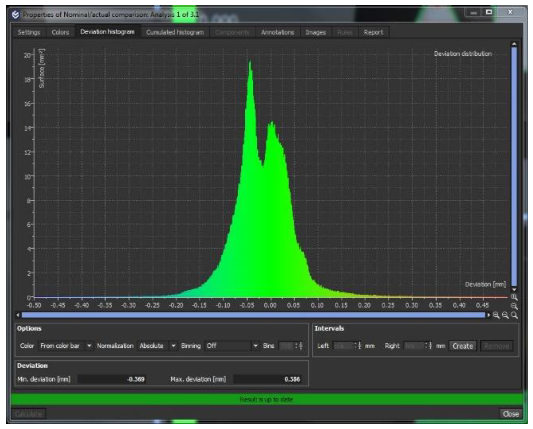
Volumetric measurement results, for which examples of histograms are given in Figure 11 and Figure 12, indicate that 95% of deviations from nominal values (errors in manufacturing of test plates) are contained within the range of ±100 μm. For the majority of plates that were printed during this study, the deviations were distributed according to Gauss distribution; 19 analysed test plates (as shown in Figure 12) showed normal distribution of deviations from nominal CAD data, and for three plates (No. 1.2; 2.3; 3.1), binominal distributions were observed (as shown in Figure 13). While Gaussian distribution indicates that only random errors occur in the manufacturing process, without systematic errors, it is difficult to draw conclusions about underlying causes of binomial deviation distributions; this effect could be attributed to a systematic error in the manufacturing process, but since the majority of samples did not show this effect, other possible causes shall be investigated in further research. Regardless, the ranges of deviations given above can be used as an expectation of the achievable accuracy of PolyJet technology-based printers when printing rather small parts.
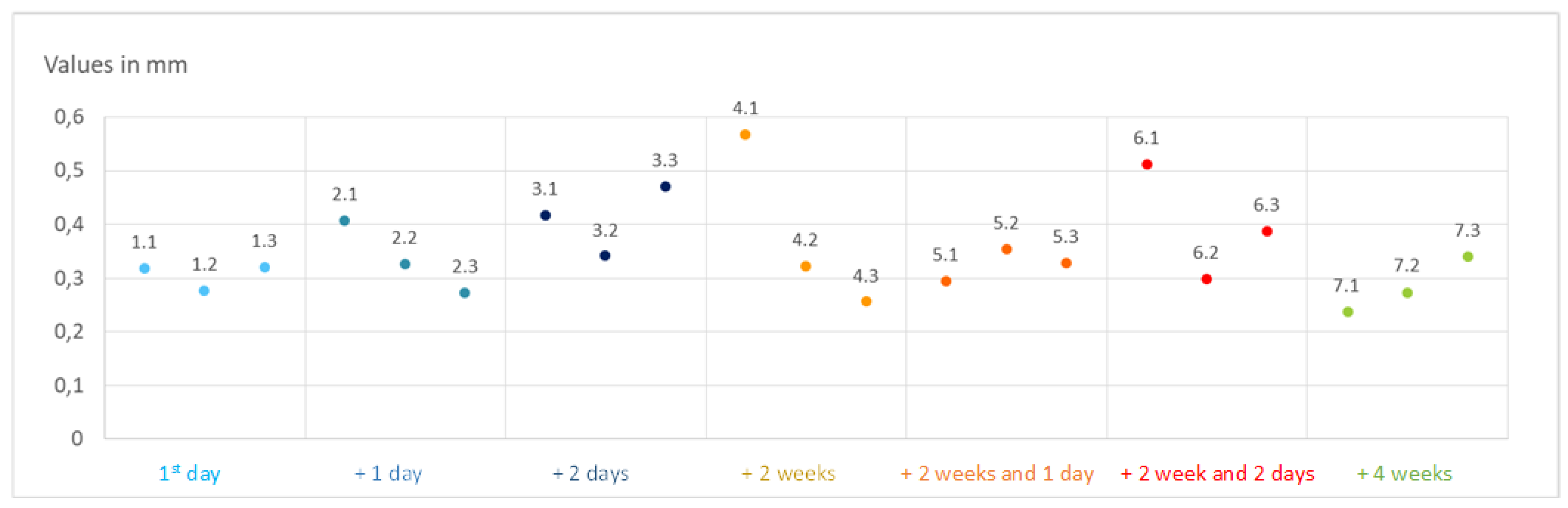
When specific measurands are analysed, it is obvious that shape errors (i.e., cylindricity) are larger than positional or dimensional errors; this can be attributed to relatively large surface roughness and small feature sizes on the test plate that was used. Finally, measurement results and subsequent analysis indicate that holes with diameters less than 0.75 mm cannot be reliably produced with the PolyJet process. This was also established in the work of author Scaravetti et al. [14] with the production of the test plate for accuracy measurement by using different technologies—one needs to know the limitations about the dimension of holes, thickness of walls, etc.
6. Conclusions
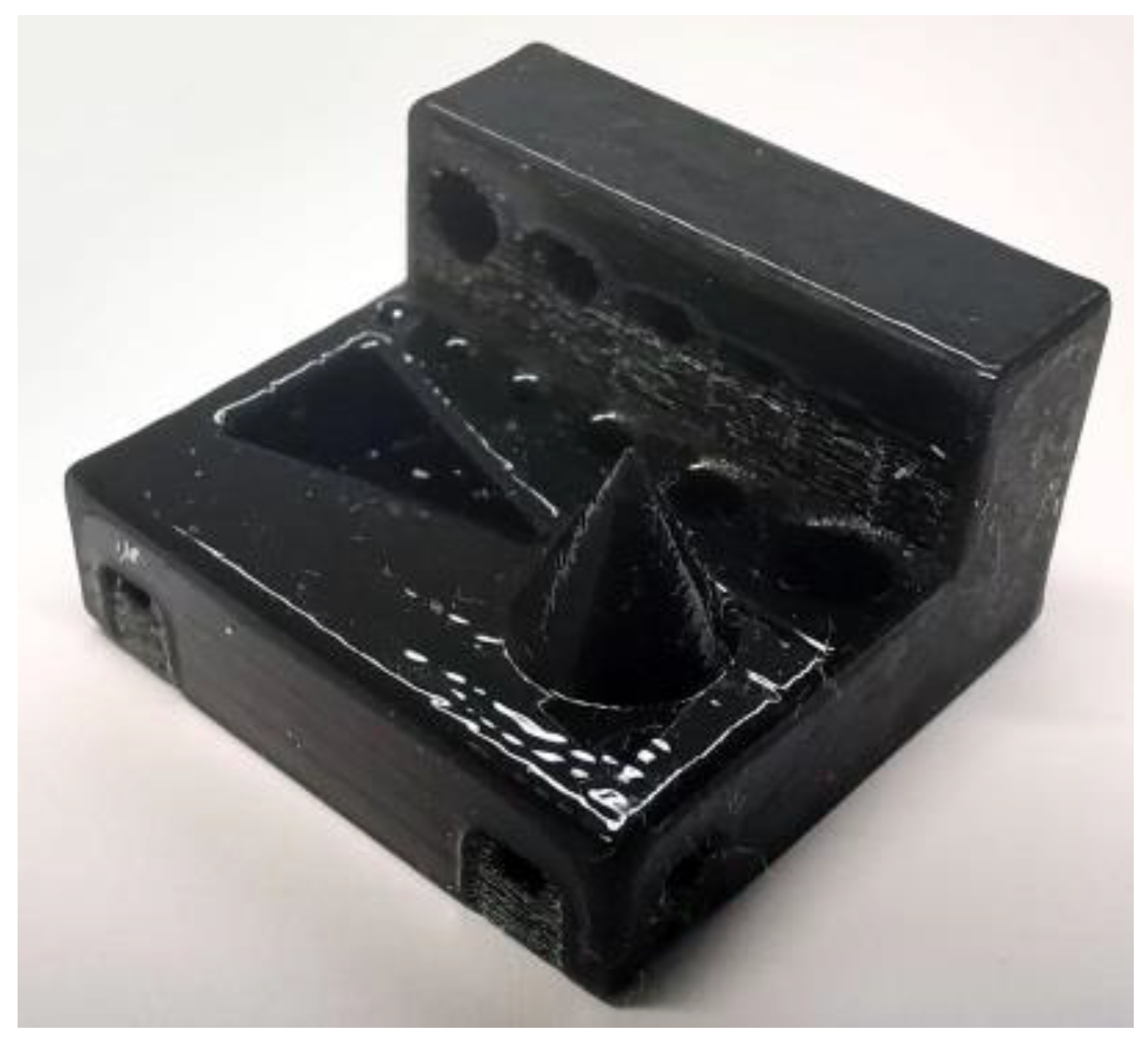
A test plate was developed to evaluate the performance of the PolyJet process and the prospect of manufacturing parts with relatively small features. The test plate had a prismatic base (21 × 20 × 6 mm) and included features such as a cone, a triangular pocket, holes (through all) and channels. Six holes were built in orientation with the diameter in the plane XY and the other six with a diameter in the plane XZ. The test plate design was made according to studied literature and conducted pre-test from which it was concluded what can be achieved with the PolyJet machine and what is crucial to measure. Analysis of results shows that PolyJet technology consistently produces parts within ±100 μm, at a 95% confidence interval, under reproducibility conditions over a 1-month period. As was the case with the accuracy, achieved repeatability for measurands (distance) in the x and y axis was significantly better than it was for the z axis, i.e., in the x and y axis, average values of measurement ranges were at 25 µm, whereas this statistical parameter in the z axis was at 49 µm. From the deviation of the shape and the deviation in the x and y direction, it can be concluded that it is better to 3D print a product day after day than to wait a week or more between manufacturing, because the products printed in one series are dimensionally more similar to each other. Additionally, the experiment showed that it takes time to stabilize the cycle, which is similar to classical production. Future work will focus on the investigation of root causes for the binomial distribution of deviations that was detected in several test plates. Additionally, an increase in used measurands is planned in order to provide greater insight into manufacturing errors of this type of technology.
Author Contributions
Concept of the paper and idea of the work, A.P.; methodology, G.B.; production of test plate, A.P. and M.R.H.; testing, M.K.; analysis G.B. and M.K.; wrote the paper A.P., G.B. and M.K.; writing—review and editing, M.R.H.; project administration, M.R.H. All authors have read and agreed to the published version of the manuscript.
Funding
This research received no external funding.
Acknowledgments
This paper is part of the research financed by 3 projects: Testing of the repeatability of 3D printed geometry financed by the Ministry of Education, Science and Sport of Croatia, H2020-WIDESPREAD-05-2017-Twinning project Increasing Excellence on Advanced Additive Manufacturing—INEX-ADAM financed by European Union and project IKARUS from European Regional Development Fund. Authors would like to thank the Ministry of Education, Science and Sport and European Union for financing of this project.
Conflicts of Interest
The authors declare no conflict of interest.
References
- Ponche, R.; Kerbrat, O.; Mognol, P.; Hascoet, J.Y. A novel methodology of design for Additive Manufacturing applied to Additive Laser Manufacturing process. Robot. Comput.-Integr. Manuf. 2014, 30, 389–398. [Google Scholar]
- Vayre, B.; Vignat, F.; Villeneuve, F. Designing for Additive Manufacturing. Procedia CIRP 2012, 3, 632–637. [Google Scholar] [CrossRef] [Green Version]
- Vayre, B.; Vignat, F.; Villeneuve, F. Identification on some design key parameters for additive manufacturing: Application on electron beam melting. Procedia CIRP 2013, 7, 264–269. [Google Scholar] [CrossRef] [Green Version]
- Hague, R.; Mansour, S.; Saleh, N. Material and design considerations for rapid manufacturing. Int. J. Prod. Res. 2004, 42, 4691–4708. [Google Scholar] [CrossRef]
- Yap, Y.L.; Wang, C.C.; Sing, S.L.; Dikshit, V.; Yeong, W.Y.; Wei, J. Material jetting additive manufacturing: An experimental study using designed metrological benchmarks. Precis. Eng. 2017, 50, 275–285. [Google Scholar] [CrossRef]
- Thompson, M.K.; Mischkot, M. Design of test parts to characterize micro additive manufacturing processes. Procedia CIRP 2015, 34, 223–228. [Google Scholar] [CrossRef] [Green Version]
- Moylan, S.; Slotwinski, J.; Cooke, A.; Jurrens, K.; Donmez, M.A. Proposal for a Standardized Test Artifact for Additive Manufacturing Machines and Processes. In Proceedings of the 2012 Annual International Solid Freeform Fabrication Symposium, Austin, TX, USA, 6–8 August 2012; pp. 902–920. [Google Scholar]
- Kim, G.D.; Oh, Y.T. A Benchmark Study on Rapid Prototyping Processes and Machines: Quantitative Comparisons of Mechanical Properties, Accuracy, Roughness, Speed, and Material Cost. Proc. Inst. Mech. Eng. Part B J. Eng. Manuf. 2008, 222, 201–215. [Google Scholar] [CrossRef]
- Meisel, N.A. Design for Additive Manufacturing Considerations for Self-Actuating Compliant Mechanisms Created via Multi-Material PolyJet 3D Printing. Ph.D. Thesis, Faculty of the Virginia Polytechnic Institute and State, Blackburg, VA, USA, 2015. [Google Scholar]
- Fahad, M.; Hopkinson, N.A. New benchmarking part for evaluating the accuracy and repeatability of Additive Manufacturing (AM) processes. In Proceedings of the 2nd International Conference on Mechanical, Production and Automobile Engineering (ICMPAE’2012), Singapore, 28–29 April 2012. [Google Scholar]
- Yang, H.Y.; Lim, J.C.; Liu, Y.C.; Qi, X.Y.; Yap, Y.L.; Dikshit, V.; Yeong, W.Y.; Wei, J. Performance evaluation of ProJet multi-material jetting 3D printer. Virtual Phys. Prototyp. 2017, 12, 95–103. [Google Scholar] [CrossRef]
- Moylan, S.; Cooke, A.; Jurrens, K.; Slotwinski, J.; Donmez, A.M. A Review of Test Artifacts for Additive Manufacturing. Natl. Inst. Stand. Technol. 2012. [Google Scholar] [CrossRef] [Green Version]
- Moylan, S.; Slotwinski, J.; Cooke, A.; Jurrens, K.; Donmez, M.A. An Additive Manufacturing Test Artifact. J. Res. Natl. Inst. Stand. Technol. 2014, 119, 429–459. [Google Scholar] [CrossRef]
- Scaravetti, D.; Dubois, P.; Duchamp, R. Qualification of rapid prototyping tools: Proposition of a procedure and a test part. Int. J. Adv. Manuf. Technol. 2008, 38, 683–690. [Google Scholar] [CrossRef] [Green Version]
- Beltrán, N.; Carriles, F.; Álvarez, B.J.; Blanco, D.; Rico, J.C. Characterization of factors influencing dimensional and geometric errors in PolyJet manufacturing of cylindrical features. Procedia Eng. 2015, 132, 62–69. [Google Scholar] [CrossRef] [Green Version]
- Cooke, A.L.; Soons, J.A. Variability in the Geometric Accuracy of Additively Manufactured Test Parts. 24 January 2020. Available online: https://sffsymposium.engr.utexas.edu/Manuscripts/2010/2010-01-Cooke.pdf (accessed on 1 February 2020).
- Kruger, O.; Baršić, G.; Pilipović, A.; Katić, M. Evaluation of measuring methods for the evaluation of Additive Manufacturing. In Proceedings of the Macroscale, Recent Developments in Traceable Dimensional Measurements, Dimensional and Related Measurements at Macroscopic Scale, Espoo, Finland, 17–19 October 2017. [Google Scholar]
- Shah, P.; Racasan, R.; Bills, P. Comparison of different additive manufacturing methods using computed tomography. Case Stud. Nondestruct. Test. Eval. 2016, 6, 69–78. [Google Scholar] [CrossRef] [Green Version]
- Stolfi, A.; Kallasseb, M.; Carlib, L.; De Chiffre, L. Enhancing the Accuracy of Computed Tomography Measurements using Data Filtering. In Proceedings of the 6th Conference on Industrial Computed Tomography (iCT 2016), Wels, Austria, 9–12 February 2016; pp. 1–6. [Google Scholar]
- Kraemer, A.; Stolfi, A.; Schneider, T.; De Chiffre, L.; Lanza, G. Traceability investigation in Computed Tomography using industry-inspired workpieces. In Proceedings of the 7th Conference on Industrial Computed Tomography (iCT 2017), Leuven, Belgium, 7–9 February 2017; pp. 1–9. [Google Scholar]
- Katić, M.; Markučič, D.; Baršić, G. Multi-spectral (W, Mo, Cu, and Ag) XCT measurements. In Proceedings of the 8th Conference on Industrial Computed Tomography (iCT 2018), Wels, Austria, 6–9 February 2018; pp. 1–5. [Google Scholar]
- Kruth, J.P.; Bartscher, M.; Carmignato, S.; Schmitt, R.; De Chiffre, L.; Weckenmann, A. Computed tomography for dimensional metrology. CIRP Ann. Manuf. Technol. 2011, 60, 821–842. [Google Scholar] [CrossRef]
- Aloisi, V.; Carmignato, S. Influence of surface roughness on X-ray computed tomography dimensional measurements of additive manufactured parts. Case Stud. Nondestruct. Test. Eval. 2016, 6, 104–110. [Google Scholar] [CrossRef]
- Kouach, M.; Tollander, S. Repeatability of Additive Manufactured Parts; Degree Project in Technology, First Cycle; KTH Royal Institute of Technology, School of Industrial Engineering and Management: Stockholm, Sweden, 2017; Available online: https://www.uppsatser.se/uppsats/cb46fcdec0/ (accessed on 10 October 2020).
- Prashanth, K.G.; Scudino, S.; Chatterjee, R.P.; Salman, O.O.; Eckert, J. Additive Manufacturing: Reproducibility of Metallic Parts. Technologies 2017, 5, 8. [Google Scholar] [CrossRef] [Green Version]
- Liou, F.W. Rapid Prototyping and Engineering applications: A Toolbox for Prototype Development; Taylor & Francis Group, CRC Press: Boca Raton, FL, USA, 2008. [Google Scholar]
- Godec, D. Influence of the Hybrid Mould on the Properties of the Injection Moulded Thermoplastic Part. Ph.D. Thesis, Faculty of Mechanical Engineering and Naval Architecture, Zagreb, Croatia, 2005. [Google Scholar]
- Gibson, I.; Rosen, D.W.; Stucker, B. Additive Manufacturing Technologies: Rapid Prototyping to Direct Digital Manufacturing; Springer: Heidelberg, Germany, 2010. [Google Scholar]
- Pilipović, A. Influence of Processing Parameters on the Properties of Polymer Prototype. Ph.D. Thesis, Faculty of Mechanical Engineering and Naval Architecture, Zagreb, Croatia, 2012. [Google Scholar]
- Rujnić-Sokele, M.; Pilipović, A.; Dimitrov, N. Application of additive manufacturing (3D printing) for the production of food packaging. In Proceedings of the 3rd Croatian Congress of Health Ecology, Tuheljske Toplice, Tuhelj, Croatia, 25–27 April 2017; Croatian Institute for public health and Croatian society for health ecology and Croatian medical association: Zagreb, Croatia, 2017. [Google Scholar]
- Bagheri, A.; Jin, J. Photopolymerization in 3D printing. Appl. Polym. Mater. 2019, 1, 593–611. [Google Scholar] [CrossRef] [Green Version]
- Udroiu, R.; Braga, I.C.; Nedelcu, A. Evaluating the Quality Surface Performance of Additive Manufacturing Systems: Methodology and a Material Jetting Case Study. Materials 2019, 12, 995. [Google Scholar] [CrossRef] [Green Version]
- Stratasys. Available online: https://www.stratasys.com/ (accessed on 25 January 2020).
- Drstvenšek, I. Layered Technologies; Faculty of Mechanical Engineering: Maribor, Slovenia, 2004; ISBN 86-435-0616-8. [Google Scholar]
- Nahum, A. GrabCAD Community. Matte or Glossy? Which Finish to Use for Your 3D Prints and When. Available online: https://grabcad.com/tutorials/matte-or-glossy-which-finish-to-use-for-your-3d-prints-and-when (accessed on 23 February 2020).
- Kumar, K.; Kumar, G.S. An experimental and theoretical investigation of surface roughness of poly-jet printed parts. Virtual Phys. Prototyp. 2015, 10, 23–34. [Google Scholar] [CrossRef]
- Baršić, G.; Pilipović, A.; Katić, M. Reproducibility of 3D printed structures. In Proceedings of the Euspen 17th International Conference & Exhibition, Hannover, Germany, 29 May–2 June 2017. [Google Scholar]
- Kechagias, J.; Stavropoulos, P.; Koutsomichalis, A.; Ntintakis, I.; Vaxevanidis, N. Dimensional Accuracy Optimization of Prototypes produced by PolyJet Direct 3D Printing Technology. In Proceedings of the International Conference on Industrial Engineering—INDE ‘14, Santorini Island, Greece, 17–21 July 2014; pp. 61–65. [Google Scholar]
- Computer Aided Technology. Connex 350 Legacy 3D Printer. Available online: https://www.cati.com/3d-printing/stratasys-3d-printers/legacy-systems/connex-350/ (accessed on 15 March 2020).
- Delgado, J.; Ciurana, J.; Reguant, C.; Cavallini, B. Studying the Repeatability in DMLS Technology Using a Complete Geometry Test Part. Innovative Developments in Design and Manufacturing; Taylor & Francis Group, CRC Press: Boca Raton, FL, USA, 2009. [Google Scholar]
- Dowling, L.; Kennedy, J.; O’Shaughnessy, S.; Trimble, D. A review of critical repeatability and reproducibility issues in powder bed fusion. Mater. Des. 2020, 186, 108346. [Google Scholar] [CrossRef]
- Tao, Y.; Li, Z.; Li, P. A Design and Fabrication Method for Wood-Inspired Composites by Micro X-ray Computed Tomography and 3D Printing. Appl. Sci. 2020, 10, 1400. [Google Scholar] [CrossRef] [Green Version]
Figure 1.
PolyJet technology [27] (printing head photo by A. Pilipović).
Figure 1.
PolyJet technology [27] (printing head photo by A. Pilipović).

Figure 2.
3D Computer aided design (CAD) model of test plate.

Figure 3.
Test plate dimensions.

Figure 4.
Position and orientation of test plates in working platform.

Figure 5.
Printed test plate.

Figure 6.
Measurands on test plate.

Figure 7.
Deviations in x axis.

Figure 8.
Deviations in y axis.

Figure 9.
Deviations in z axis.

Figure 10.
Shape deviation—cone.

Figure 11.
Shape deviation—cylinder.

Figure 12.
Volumetric deviation from CAD model on test plate No. 5.3. Good approximation of Gaussian distribution, centred around zero, indicates that there are no systematic errors in the production process.
Figure 12.
Volumetric deviation from CAD model on test plate No. 5.3. Good approximation of Gaussian distribution, centred around zero, indicates that there are no systematic errors in the production process.

Figure 13.
Volumetric deviation from CAD model on test plate No. 3.1. A bimodal distribution can be seen, suggesting that a systematic error source was present during manufacturing.
Figure 13.
Volumetric deviation from CAD model on test plate No. 3.1. A bimodal distribution can be seen, suggesting that a systematic error source was present during manufacturing.


Table 1.
Plan of printing by days.
| Day | Sample Mark | ||
|---|---|---|---|
| 1st day | 1.1 | 1.2 | 1.3 |
| 2nd day (+1 day) | 2.1 | 2.2 | 2.3 |
| 3rd day (+2 days) | 3.1 | 3.2 | 3.3 |
| 15th day (+2 weeks) | 4.1 | 4.2 | 4.3 |
| 16th day (+2 weeks and 1 day) | 5.1 | 5.2 | 5.3 |
| 17th day (+2 weeks and 2 days) | 6.1 | 6.2 | 6.3 |
| 29th day (+4 weeks) | 7.1 | 7.2 | 7.3 |
Table 2.
Results of distance deviations in all three axes.
| 1.1 | 1.2 | 1.3 | 2.1 | 2.2 | 2.3 | 3.1 | 3.2 | 3.3 | |
| dx, mm | 0.072 | 0.048 | 0.047 | 0.062 | 0.053 | 0.046 | 0.033 | 0.022 | 0.076 |
| dy, mm | 0.100 | 0.039 | 0.019 | 0.064 | 0.077 | 0.066 | 0.020 | 0.034 | 0.034 |
| dz, mm | 0.107 | 0.102 | 0.089 | 0.114 | 0.112 | 0.087 | 0.114 | 0.068 | 0.089 |
| 4.1 | 4.2 | 4.3 | 5.1 | 5.2 | 5.3 | 6.1 | 6.2 | 6.3 | |
| dx, mm | 0.021 | 0.004 | 0.026 | 0.015 | 0.023 | −0.002 | −0.008 | 0.007 | 0.007 |
| dy, mm | 0.026 | 0.001 | 0.005 | 0.002 | 0.031 | 0.004 | −0.004 | −0.005 | −0.010 |
| dz, mm | 0.197 | 0.061 | 0.056 | 0.069 | 0.087 | 0.078 | 0.136 | 0.085 | 0.075 |
| 7.1 | 7.2 | 7.3 | |||||||
| dx, mm | −0.005 | 0.023 | 0.010 | ||||||
| dy, mm | 0.006 | 0.002 | 0.003 | ||||||
| dz, mm | 0.115 | 0.080 | 0.113 |
Table 3.
Results of shape deviation measurements.
| Values in mm | 1.1 | 1.2 | 1.3 | 2.1 | 2.2 | 2.3 | 3.1 | 3.2 | 3.3 |
| cone | 0.086 | 0.097 | 0.122 | 0.094 | 0.088 | 0.102 | 0.111 | 0.123 | 0.086 |
| cylinder | 0.318 | 0.275 | 0.320 | 0.406 | 0.325 | 0.272 | 0.416 | 0.340 | 0.469 |
| 4.1 | 4.2 | 4.3 | 5.1 | 5.2 | 5.3 | 6.1 | 6.2 | 6.3 | |
| cone | 0.077 | 0.067 | 0.068 | 0.067 | 0.059 | 0.065 | 0.07 | 0.072 | 0.073 |
| cylinder | 0.566 | 0.322 | 0.255 | 0.293 | 0.352 | 0.328 | 0.511 | 0.297 | 0.386 |
| 7.1 | 7.2 | 7.3 | |||||||
| cone | 0.075 | 0.064 | 0.063 | ||||||
| cylinder | 0.237 | 0.273 | 0.340 |
© 2020 by the authors. Licensee MDPI, Basel, Switzerland. This article is an open access article distributed under the terms and conditions of the Creative Commons Attribution (CC BY) license (http://creativecommons.org/licenses/by/4.0/).
Share and Cite
MDPI and ACS Style
Pilipović, A.; Baršić, G.; Katić, M.; Rujnić Havstad, M. Repeatability and Reproducibility Assessment of a PolyJet Technology Using X-ray Computed Tomography. Appl. Sci. 2020, 10, 7040. https://doi.org/10.3390/app10207040
AMA Style
Pilipović A, Baršić G, Katić M, Rujnić Havstad M. Repeatability and Reproducibility Assessment of a PolyJet Technology Using X-ray Computed Tomography. Applied Sciences. 2020; 10(20):7040. https://doi.org/10.3390/app10207040
Chicago/Turabian StylePilipović, Ana, Gorana Baršić, Marko Katić, and Maja Rujnić Havstad. 2020. "Repeatability and Reproducibility Assessment of a PolyJet Technology Using X-ray Computed Tomography" Applied Sciences 10, no. 20: 7040. https://doi.org/10.3390/app10207040
Note that from the first issue of 2016, this journal uses article numbers instead of page numbers. See further details here.