True Equalization of Polarization-Dependent Loss in Presence of Fast Rotation of SOP †


State Key Laboratory of Information Photonics and Optical Communications, Beijing University of Posts and Telecommunications, Beijing 100876, China
*
Author to whom correspondence should be addressed.
†
This paper is extended version of paper published in the Optical Fiber Communications Conference and Exhibition 2020 held in San Diego, CA, USA, 8–12 March 2020.
Appl. Sci. 2020, 10(11), 3844; https://doi.org/10.3390/app10113844
Submission received: 26 April 2020
/
Revised: 21 May 2020
/
Accepted: 29 May 2020
/
Published: 31 May 2020
(This article belongs to the Section Optics and Lasers)
Abstract
:In an optical fiber communication system, polarization-dependent loss (PDL), referring to polarization-dependent optical power attenuation, might be a main system performance limiting factor. PDL causes a difference in signal power and imbalance of optical signal-to-noise ratio (OSNR) between the two polarization branches. The OSNR asymmetry will eventually deteriorate the overall system performance. At present, most of the equalization methods of PDL in the literature can only accomplish power imbalance equalization and are, thus, not the true equalization of PDL. Besides, in some extreme environments, like lightning strikes, Kerr and Faraday effects would generate ultra-fast rotation of state of polarization (RSOP), as fast as mega-radian per second. The fast RSOP in combination with PDL makes the eigenmodes of the PDL randomly time-varying, which will put a heavy burden on the equalization module of the receiver. Faced with this dilemma, in this paper, we propose a scheme for the true equalization of PDL in the presence of fast RSOP through an approach based on the combination of the polarization-time code and Kalman filter. The proposed approach is proved to be very effective and provides significant performance. With a 1.2 dB OSNR penalty, it can jointly equalize large PDL (7 dB) and fast RSOP (up to 1 Mrad/s).
1. Introduction
High-order modulation, polarization-division multiplexing (PDM), and coherent detection are very crucial techniques in optical communication systems for pursuing higher spectrum efficiency (SE). Furthermore, the integration of digital signal processing (DSP) in coherent receivers enables most of the impairments experienced by the optical signal, such as chromatic dispersion (CD), polarization mode dispersion (PMD), carrier frequency offset (CFO), and carrier phase noise (CPN), to be fully compensated in the electric domain [1]. Unfortunately, polarization-dependent loss (PDL), which induces polarization-dependent optical power fluctuations, remains the main limiting impairment and cannot be efficiently compensated by the state-of-art equalization algorithms at the receiver side [2]. PDL arises from some of the in-line components, such as isolators, multiplexers, amplifiers, and couplers. In long-haul links, we might have to face the problem of large PDL values of several dB.
The PDL effect on PDM signals not only results in the inequality of signal power, most importantly, it causes the imbalance of optical signal-to-noise ratio (OSNR) between the two polarizations of a PDM signal. The OSNR asymmetry will cause quite different bit-error-rate (BER) degradations between two polarizations signals, and this may lead to significant penalties to the system performance. At present, lots of the equalization methods of PDL in the literature such as the multiple-input-multiple-output (MIMO)-based equalizer or 3D Stokes space method can only accomplish power imbalance equalization; therefore, they are not the true equalization of PDL [3,4,5,6,7,8,9].
In fact, the OSNR asymmetry in optical communication is similar to frequency-selective fading in multi-antenna wireless channels, which can be mitigated by space–time (ST) codes. The idea can be carried over and employed. In 2010, Mumtaz et al. first introduced these codes in PDM systems for PDL mitigation and renamed it to polarization-time code (PTC), which has been proven to be very effective to truly mitigate PDL [10,11,12,13]. In their works, they supposed having perfect channel state information, or used a training sequence (TS) to estimate the channel matrix prior to implementation of the polarization-time (PT) decode at the receiver. However, there is no channel state information at the receiver. In addition, for the single-carrier systems, we prefer a blind equalizer adopted before the PT decoder at the receiver. Furthermore, in some extreme environments, like violent vibrations when trains pass by and lightning strikes on rainy days, an ultra-fast rotation of state of polarization (RSOP) would be induced with a rate of mega-radian per second [14,15,16,17]. The fast RSOP in combination with large PDL will make the eigenmodes of the PDL randomly time-varying, putting a heavy burden on the DSP equalizer.
The Kalman filter (KF) is an optimum adaptive filter algorithm, which has been widely studied for lots of kinds of impairment equalizations in optical communication in recent years. There has been a significant number of publications that have reported KF-based equalization methods covering phase noise tracking, carrier-frequency offset estimation [18,19,20], and nonlinear mitigation [21]. Particularly, thanks to the fast convergence ability of the KF, it achieved great success in ultra-fast RSOP tracking [22,23,24,25,26,27,28,29].
Inspired by the previous works, in this paper, we propose a method for achieving the true equalization of PDL in the presence of ultra-fast RSOP by utilizing a polarization-time code combined with the Kalman filter. This scheme is proven to be very effective. With an approximate 1.2 dB OSNR penalty, it exhibits an equalization capacity with a PDL tolerance as large as 7 dB and a fast RSOP tolerance (up to 1 Mrad/s). The structure of this paper is as follows. In Section 2, we first elaborate the concept of PDL and its influence on PDM signals. Then, we analyze the combined effect of PDL and RSOP in an optical fiber. In Section 3, we simplify the polarization model, and based on the simplified model, we design a scheme that can truly equalize the combined impairments of PDL and ultra-fast RSOP, which enables the PDL compensation by the polarization-time code and RSOP tracking by the Kalman filter. The method performance is assessed in Section 4. At last, a conclusion is drawn in Section 5.
2. The Effect of PDL with the Presence of RSOP
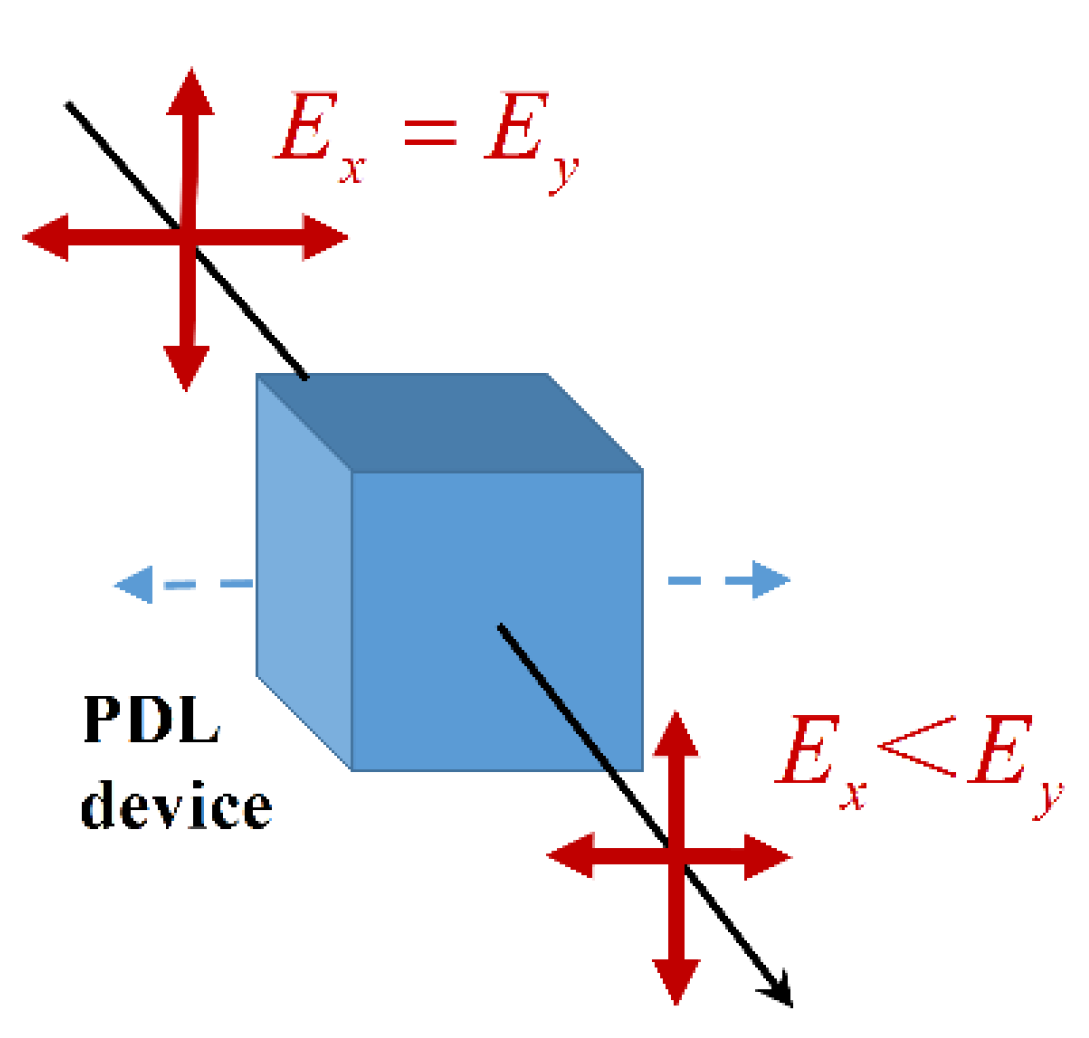
PDL mainly comes from optical devices, which refers to the polarization-dependent attenuation of optical power to input signals. As shown in Figure 1, when a PDM signal passes through an optical component that has a pair of orthogonal high- and low-loss eigenmodes, the two polarizations Ex and Ey are transmitted along the high-loss eigen-mode and the low-loss eigen-mode, respectively; therefore, their losses are different, and the output power of the two orthogonal polarizations are also different. The PDL matrix can be expressed as
where and denote the amplitude ratio angle and phase difference, respectively. The two column vectors and in rotation matrix represent eigenmodes of PDL related to the high and low losses, which are actually the two orthogonal elliptical states of polarization (SOP). represents the PDL ratio, and the diagonal matrix represents the attenuation difference between the strongly and weakly attenuated SOP. The PDL value in dB is expressed by
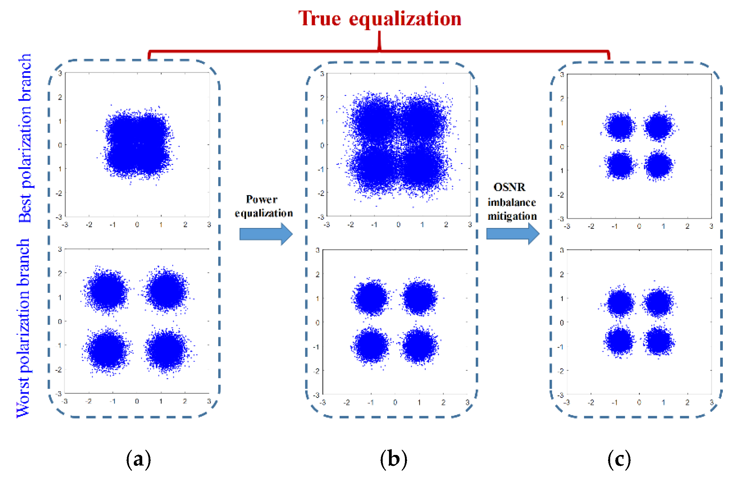
PDL not only means the inequality of signal powers but also the OSNR imbalance between the two polarizations of a PDM signal. Figure 2a shows a PDL-induced constellation map of PDM signals. For each subfigure, the top row shows the strongly attenuated polarization branch and the bottom row represents the weakly attenuated polarization branch. Unfortunately, lots of PDL compensations only realize the power equalization; in this case, as shown in Figure 2b, the OSNR imbalance between the two polarizations is still unsolved. Hence, the true equalization of PDL should include the power equalization and the BER recovery caused by OSNR asymmetry, as shown in Figure 2c.
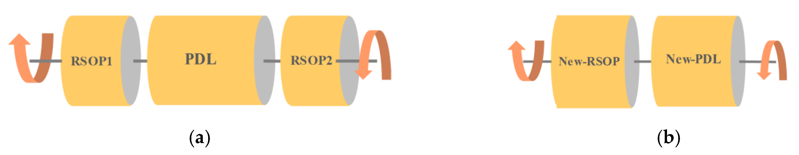
In addition, RSOP and PDL may exist simultaneously in the optical fiber links. When we face the joint effect of RSOP and PDL, the generally adopted impairment model is RSOP1 + PDL + RSOP2, which is illustrated in Figure 3a and Equation (3). In this model, two matrices before and after the PDL matrix represent two arbitrary RSOP1 and RSOP2, which are time-varying in general.
where . can take a similar form of matrix .
Based on the above analysis, we can conclude that the true PDL equalization scheme in the presence of RSOP should include the following three steps: (1) Obtaining decoupling model when PDL and RSOP coexist; (2) the power imbalance equalization and the RSOP tracking; (3) BER recovery caused by OSNR asymmetry. The three steps will be designed individually in Section 3.
3. The True Equalization of PDL in the Presence of Fast RSOP
3.1. Obtaining Decoupling Model When PDL and RSOP Coexist
When PDL and RSOP coexist in the form of the generally adopted model of RSOP1 + PDL + RSOP2, as shown in Figure 3a, a decoupling model is needed for simplicity. We rewrite Equation (3) and finally obtain Equation (4).
According to Equation (4), is equivalent to a new RSOP (denoted as ), and is equivalent to a new eigenmode matrix of PDL (denoted as ); thus, constitutes a new PDL matrix (denoted as ), which has the same attenuation parameter and new eigenmodes . Therefore, the polarization model can be decoupled as a new-RSOP and a new-PDL, which are shown in Figure 3b. In this way, RSOP and PDL are decoupled. Consequently, the compensation problem is designed as the first-stage compensation for PDL (balance power inequality) and the second-stage equalization of RSOP.
3.2. The Power Equalization and RSOP Tracking
After decoupling of the combined PDL and RSOP, we can then equalize them separately. We first treat the power imbalance equalization and RSOP tracking. We use the 3D Stokes space method [3] and Kalman filter to carry out this treatment. The 3D Stokes space provides a visual representation of the light SOP. By neglecting the common phase, the received optical signals can be represented with the Jones vector in the following form:
where , are the amplitudes of two x- and y-polarization signals, and is the phase difference. denotes the four quadrature phase-shift keying (QPSK) constellation symbols in the x- and y-polarization constellation planes. The Stokes parameters of the signals represented in Stokes space can be obtained from the Jones vector by using the relation , where is the Pauli matrix.
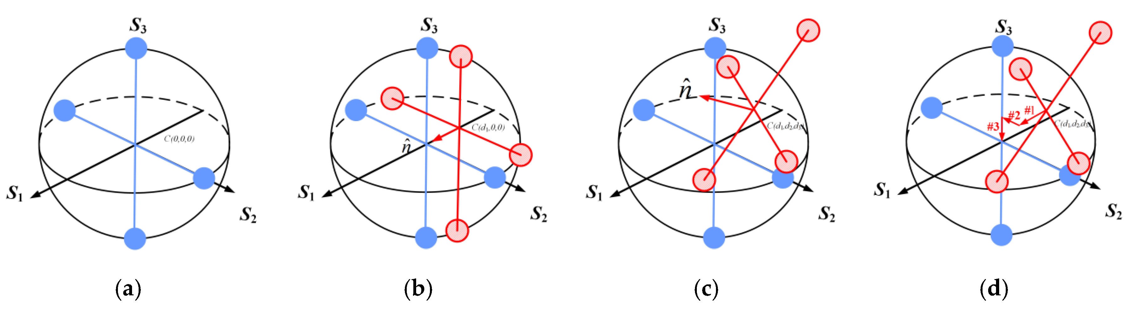
As the amplitude in the x- and y-polarizations are the same and equals zero, for the ideally compensated PDM-QPSK signals, the center of gravity of the constellations is at the origin of the Poincaré sphere in Stokes space (denoted as ), as shown in Figure 4a. When the signals suffer from PDL, their Jones vector will change to
whose corresponding Stokes vector components are
where . We can obtain the mean value of each Stokes parameters as
which means that when a power imbalance between the two polarization tributaries exists, the center of gravity of the constellation will shift from the origin (denoted as ), as shown in Figure 4b. When the signals suffer from both RSOP and PDL, the power inequality induced by PDL will cause a shift in the center of gravity of the constellation in Stokes space from the origin point of the Poincaré sphere, and the RSOP will cause a decline in the constellation structure, as shown in Figure 4c. In this case, we can move and then the entire constellation structure by the three steps of rotations and shifting until this returns to the original position. This procedure of balancing the PDL-induced power inequality is shown in Figure 4d.
After power imbalance equalization, the Kalman filter is applied to monitor and recover RSOP. We have investigated the Kalman filter structure thoroughly [23,24,25,26] and found three key issues that we can design to let our Kalman filter structure be the most effective: (1) Select the right compensation matrices for compensating RSOP; (2) decide which state parameters should be correctly chosen; (3) design the appropriate measurement vector and innovation vector. Now, we will explain these issues in detail one by one.
- (1)
- (2)
- Based on the RSOP compensation matrix in Equation (10), we decide the state vector asIt reflects the three independent parameters of RSOP.
- (3)
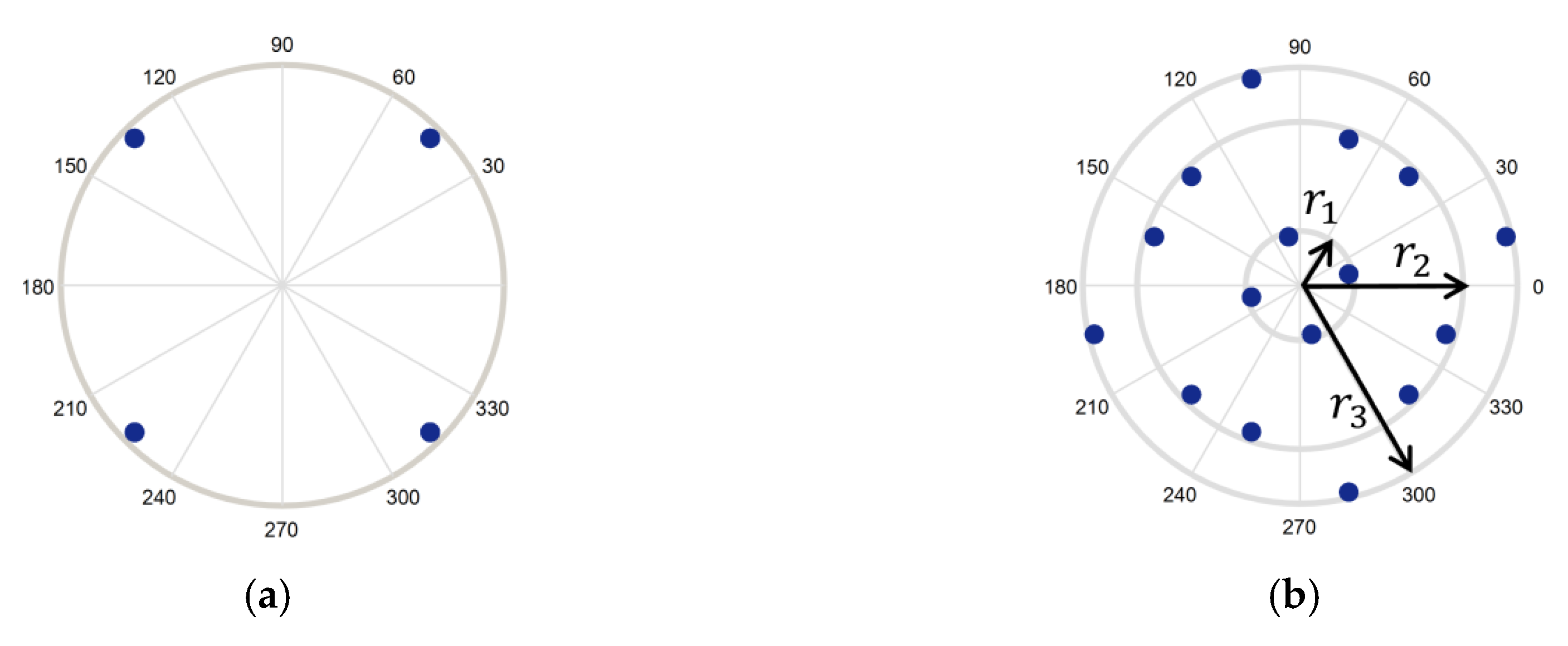
- The choice of measurement vector is based on the location of the ideal constellation points after compensation. As for the Golden-coded QPSK signal, the ideal constellation points are located at three rings with the radii r1, r2, and r3, as shown in Figure 5b. Thus, we design as:where and represent the equalized signal and its complex conjugate. Therefore, we choose the innovation as:where is the zero matrix, which means the ideally equalized PDM signal’s constellation points located on the three radii of the three circles on two x- and y-polarization constellation planes.
3.3. BER Recovery by Polarization-Time Code
As mentioned in Section 2, the finished works described in Section 3.2, power inequality balance and RSOP tracking, are only half of the full works; step (3), mentioned previously—OSNR imbalance—should be solved next. One effective solution is to use polarization-time code. It linearly combines the modulated symbols on two orthogonal polarizations. Here, we focus on the Golden code, a kind of polarization-time code whose coding matrix is:
where , , , , and are data symbols. The first row represents the code modulated on the x-polarization and the second row represents the code on the orthogonal y-polarization. The Golden code does not introduce any redundancy compared to the uncoded case, because four symbols are transmitted on two polarization tributaries during two symbol periods.
At the receiver, the optimal method to recover the information data is the maximum likelihood (ML) decoder, which is to estimate the transmitted symbols through minimizing the following distance with the received symbols Y.
where A is the alphabet and H is the channel state information matrix, which need to be obtained at the receiver.
Now, the three steps have been completed: Obtaining the decoupling model when RSOP and PDL are co-existing, equalizing the power imbalance in Stokes space combined with tracking RSOP by the Kalman filter, and recovering BER asymmetry using the polarization-time code. Therefore, the PDL in the presence of RSOP is truly equalized.
4. Simulation and Analysis
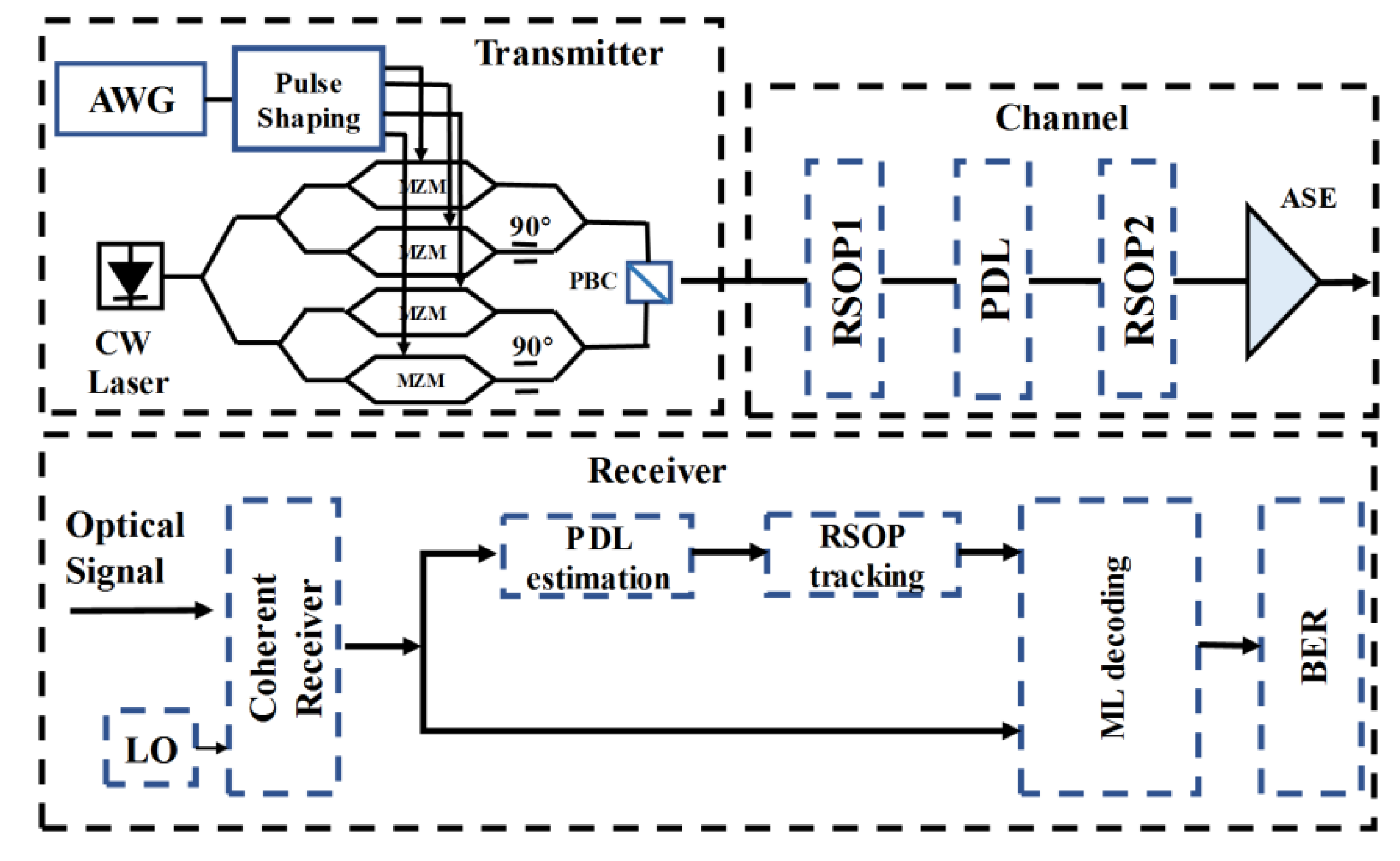
In order to verify the proposed method for joint equalization of PDL and RSOP, we built a simulation platform of a 112 Gbit/s PDM-QPSK coherent system in MATLAB (R2019b, MathWorks, Natick, MA, USA, 2019), as shown in Figure 6. The transmitter sends the Golden-coded signal. Subsequently, in the fiber channel, the optical signal experiences RSOP, PDL, and amplified spontaneous emission (ASE) noise. In this simulation, we assume RSOP is dynamic and PDL is a deterministic phenomenon as it varies slowly. At the receiver, after coherent detection, the signals enter the digital signal processing (DSP) module. At the DSP side, the received signal Y is divided into two branches. The upper branch is applied to obtain channel state information. PDL is estimated and the power inequality is equalized by utilizing the 3D Stokes space method, and RSOP parameters are tracked with the Kalman filter. After that, the signal in the lower branch and the obtained channel information are sent to the ML decoder for symbol decision by Equation (15).
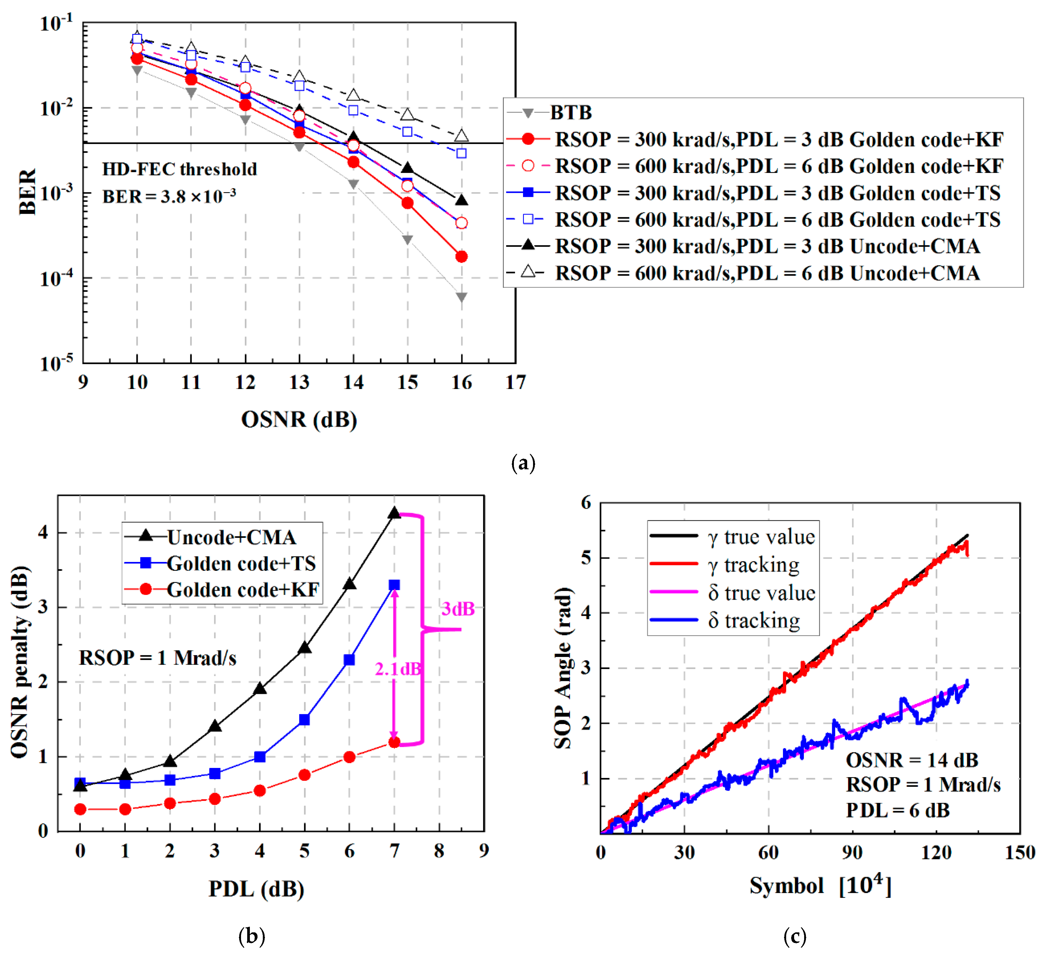
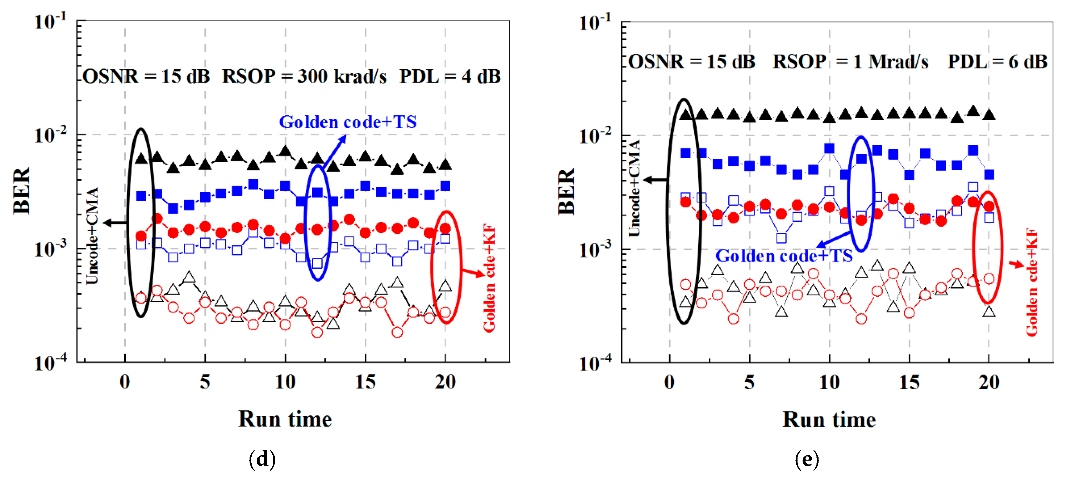
Figure 7 depicts the performance of the proposed Golden code and Kalman filter equalization method (marked as Golden code + KF). For references, we also simulate the following two methods: The first one is an uncoded signal at the transmitter with constant modulus algorithm (CMA) equalization at the receiver (marked as Uncode + CMA); and the second is a golden-coded signal at the transmitter with training sequence (TS)-assisted RSOP tracking at the receiver (marked as Golden code + TS). The idea for the TS-assisted RSOP tracking scheme is based on the assumption that the TS and the entire data block have suffered from the same RSOP. Hence, the RSOP tracking ability of TS depends on how frequent TS is inserted in the data block. Obviously, the more frequent the TS that is inserted, the more redundancy there will be. In this paper, we design to insert 10 TSs in every 400 symbols, which means 2.5% of the redundancy. Figure 7a illustrates the BER depending on the OSNR with different PDLs and speeds of variation of RSOP. We can see that using the hard decision forward-error correction (HD-FEC) threshold (BER = 3.8 × 10⁻³) as the criterion [30,31,32], the Golden code + KF method exhibits an apparently better performance than those of the uncode + CMA and Golden code + TS schemes under different conditions of RSOP from 300 to 600 krad/s and PDL from 3 to 6 dB. In Figure 7b, we discuss the PDL-induced OSNR penalty at BER = 3.8 × 10⁻³ under the severe impairment environment of RSOP = 1 Mrad/s. Thanks to the coding gain brought by the Golden code and the excellent RSOP tracking ability of the Kalman filter, at PDL up to 7 dB, the proposed Golden code + KF scheme only needs an OSNR penalty of approximately 1.2 dB. It is worth mentioning that the proposed method wins 3 dB OSNR than the uncode + CMA scheme, and 2.1 dB OSNR than the Golden code + TS scheme. Therefore, it is obvious that the Golden code + KF method has an overwhelming advantage over the other two methods. At the same time, RSOP tracing performance of the proposed Golden code + KF method is also shown in Figure 7c. The polarization impairment is assumed to be 1 Mrad/s RSOP and 6 dB PDL under 14 dB OSNR. In Figure 7c, the black line and the red line represent the true value and tracking value of γ, respectively, and the pink line and the black line represent the true value and tracking value of δ, respectively. We can see that the RSOP tracking curve converges quickly, and the tracking results of rotation angles γ and δ agree well with the original linearly increased ones, which means the proposed Golden code + KF method is indeed effective to track ultra-fast RSOP. In Figure 7a,b, we discuss the average BER on the worst and the best polarization cases. Now, we study the worst and the best BERs of the PDM signal separately. The results are shown in Figure 7d,e (the solid point is the worst polarization case and the dashed point is the best polarization case). We study both the weak impairment condition (RSOP = 300 krad/s, PDL = 4 dB, and OSNR = 15 dB), as shown in Figure 7d, and the severe impairment condition (RSOP = 1 Mrad/s, PDL = 6 dB, and OSNR = 15 dB), as shown in Figure 7e. We can see that the proposed Golden code + KF method can effectively mitigate the different BERs of the two polarization branches in both weak and extreme scenarios.
5. Conclusions
In this paper, we make clear that a true PDL equalization should include either power equalization or BER recovery, the latter of which, though, is frequently ignored in the literature. Meanwhile, in some extreme scenarios, the ultra-fast RSOP would be induced due to lightning striking and vibration. The fast RSOP in combination with PDL will put a heavy burden on the DSP equalization module. Faced with this dilemma, we proposed a method to implement the true equalization of the combined effect of PDL and ultra-fast RSOP using the Kalman filter and Golden code. First, we simplified the polarization model and then equalized the power imbalance using the 3D Stokes method and tracked the RSOP using the Kalman filter. Finally, we recovered BER asymmetry using the Golden code. The presented approach was evaluated in a 28-GBaud PDM QPSK coherent system and compared with Uncode + CMA and Golden code + TS methods. It was clear that the proposed Golden code + KF scheme provided a significant performance. With an approximate 1.2 dB OSNR penalty, it can compensate up to 7 dB PDL under 1 Mrad/s ultra-fast RSOP, which has the important gain compared to the Uncode + CMA and Golden code + TS schemes and has no coding redundancy.
Author Contributions
Conceptualization, N.C. and X.Z.; methodology, N.C. and W.Z.; software, N.C.; data curation, N.C.; writing—original draft preparation, N.C; writing—review and editing, X.Z.; visualization, X.T.; supervision, L.X. All authors have read and agreed to the published version of the manuscript.
Funding
This research was funded by the National Natural Science Foundation of China (61571057, 61527820, 61575082), Fund of State Key Laboratory of IPOC (BUPT) (No. IPOC2019ZZ02), P. R. China and BUPT Excellent Ph.D. Students Foundation (CX2019317).
Conflicts of Interest
The authors declare no conflict of interest.
References
- Savory, S. Digital filters for coherent optical receivers. Opt. Express 2008, 16, 804–817. [Google Scholar] [CrossRef] [PubMed]
- Awwad, E.; Tran, P.; Charlet, G. A low-complexity implementation of full-rate polarization-time codes for PDL mitigation in single-carrier optical transmissions using the constant modulus algorithm. In Proceedings of the European Conference and Exhibition on Optical Communications, Dusseldorf, Germany, 18–22 September 2016. [Google Scholar]
- Muga, N.; Pinto, A. Digital PDL compensation in 3D Stokes space. J. Lightwave Technol. 2013, 31, 2122–2130. [Google Scholar] [CrossRef]
- Muga, N.; Pinto, A. Adaptive 3-D stokes space-based polarization demultiplexing algorithm. J. Lightwave Technol. 2014, 32, 3290–3298. [Google Scholar] [CrossRef]
- Muga, N.; Pinto, A. Extended Kalman filter vs. geometrical approach for Stokes space-based polarization demultiplexing. J. Lightwave Technol. 2015, 33, 4826–4833. [Google Scholar] [CrossRef]
- Yu, Z.; Yi, X.; Zhang, J.; Deng, M.; Zhang, H.; Qiu, K. Modified constant modulus algorithm with polarization demultiplexing in Stokes space in optical coherent receiver. J. Lightwave Technol. 2013, 31, 3203–3209. [Google Scholar] [CrossRef]
- Yu, Z.; Yi, X.; Zhang, J.; Zhao, D.; Qiu, K. Experimental demonstration of polarization-dependent loss monitoring and compensation in Stokes space for coherent optical PDM-OFDM. J. Lightwave Technol. 2014, 32, 3926–3931. [Google Scholar]
- Ishimura, S.; Nishimura, K. Decision-directed adaptive PDL-compensation algorithm for stokes vector receivers. In Proceedings of the European Conference and Exhibition on Optical Communications, Rome, Italy, 23–27 September 2018. [Google Scholar]
- Szafraniec, B.; Nebendahl, B. Polarization demultiplexing in Stokes space. Opt. Express 2010, 18, 17928–17939. [Google Scholar] [CrossRef] [PubMed]
- Mumtaz, S.; Rekaya, G.; Jaouen, Y. Space-time codes for optical fiber communication with polarization multiplexing. In Proceedings of the IEEE International Conference on Communications, Cape Town, South Africa, 23–27 May 2010. [Google Scholar]
- Mumtaz, S.; Li, J.; Koenig, S.; Jaouen, Y.; Schmogrow, R.; Othman, G.; Leuthold, J. Experimental demonstration of PDL mitigation using polarization-time coding in PDM-OFDM systems. In Proceedings of the Signal Processing in Photonic Communications, Toronto, ON, Canada, 12–15 June 2011. [Google Scholar]
- Mumtaz, S.; Othman, G.; Jaouen, Y.; Li, J.; Koenig, S.; Leuthold, J.; Schmogrow, R. Alamouti code against PDL in polarization multiplexed systems. In Proceedings of the Signal Processing in Photonic Communications, Toronto, ON, Canada, 12–15 June 2011. [Google Scholar]
- Mumtaz, S.; Othman, G.; Jaouen, Y. PDL mitigation in PolMux OFDM systems using Golden and Silver polarization-time codes. In Proceedings of the Optical Fiber Communication Conference, San Diego, CA, USA, 21–25 March 2010. [Google Scholar]
- Lightning Strikes and 100G Transport. Available online: https://cdn.extranet.coriant.com/resources/White-Papers/Coriant_WP_Lightning_Strikes_and_100G_Transport.pdf (accessed on 11 March 2016).
- Lightning Affects Coherent Optical Transmission in Aerial Fiber. Available online: http://www.lightwaveonline.com/articles/2016/03/lightning-affects-coherent-optical-transmission-in-aerial-fiber.html (accessed on 2 March 2016).
- Are Ultrafast SOP Events Affecting Your Coherent Receivers? Available online: https://newridgetech.com/are-ultrafast-sop-events-affecting-your-receivers. (accessed on 16 February 2016).
- Charlton, D.; Clarke, S.; Doucet, D.; O’Sullivan, M.; Peterson, D.L.; Wilson, D.; Wellbrock, G.; Bélanger, M. Field measurements of SOP transients in OPGW, with time and location correlation to lightning strikes. Opt. Express 2017, 25, 9689–9696. [Google Scholar] [CrossRef] [PubMed]
- Inoue, T.; Namiki, S. Carrier recovery for M-QAM signals based on a block estimation process with Kalman filter. Opt. Express 2014, 22, 15376–15387. [Google Scholar] [CrossRef] [PubMed]
- Qian, X.; Yang, Y.; Zhang, Q.; Cao, H.; Yao, Y. Adaptive and joint frequency offset and carrier phase estimation based on Kalman filter for 16QAM signals. Opt. Commun. 2019, 430, 336–341. [Google Scholar]
- Pakala, L.; Schmauss, B. Extended Kalman filtering for joint mitigation of phase and amplitude noise in coherent QAM systems. Opt. Express 2016, 24, 6391–6401. [Google Scholar] [CrossRef] [PubMed]
- Zibar, D.; Piels, M.; Jones, R.; Schäeffer, C. Machine learning techniques in optical communication. J. Lightwave Technol. 2016, 34, 1442–1452. [Google Scholar] [CrossRef] [Green Version]
- Szafraniec, B.; Marshall, T.S.; Nebendahl, B. Performance monitoring and measurement techniques for coherent optical systems. J. Lightwave Technol. 2013, 31, 648–663. [Google Scholar] [CrossRef]
- Cui, N.; Zhang, X.; Zheng, Z.; Xu, H.; Zhang, W.; Tang, X.; Xi, L.; Fang, Y.; Li, L. Two-parameter-SOP and three-parameter-RSOP fiber channels: Problem and solution for polarization demultiplexing using Stokes space. Opt. Express 2018, 26, 21170–21183. [Google Scholar] [CrossRef] [PubMed]
- Cui, N.; Zheng, Z.; Zhang, X.; Yi, W.; Guo, R.; Zhang, W.; Tang, X.; Xu, H.; Xi, L. Joint blind equalization of CD and RSOP using a time-frequency domain Kalman filter structure in Stokes vector direct detection system. Opt. Express 2019, 27, 11557–11570. [Google Scholar] [CrossRef] [PubMed]
- Zheng, Z.; Cui, N.; Xu, H.; Zhang, X.; Zhang, W.; Xi, L.; Fang, Y.; Li, L. Window-split structured frequency domain Kalman equalization scheme for large PMD and ultra-fast RSOP in an optical coherent PDM-QPSK system. Opt. Express 2018, 26, 7211–7226. [Google Scholar] [CrossRef] [PubMed]
- Yi, W.; Zheng, Z.; Cui, N.; Zhang, X.; Qiu, L.; Zhang, N.; Xi, L.; Zhang, W.; Tang, X. Joint equalization scheme of ultra-fast RSOP and large PMD compensation in presence of residual chromatic dispersion. Opt. Express 2019, 27, 21896–21913. [Google Scholar] [CrossRef] [PubMed]
- Zhang, Q.; Yang, Y.; Zhong, K.; Liu, J.; Wu, X.; Yao, Y. Joint polarization tracking and channel equalization based on radius-directed linear Kalman filter. Opt. Commun. 2018, 407, 142–147. [Google Scholar] [CrossRef]
- Yang, Y.; Cao, G.; Zhong, K.; Zhou, X.; Yao, Y.; Alan, P.T.; Lu, C. Fast polarization-state tracking scheme based on radius-directed linear Kalman filter. Opt. Express 2015, 23, 19673–19680. [Google Scholar] [CrossRef] [PubMed]
- Li, Y.; Hu, S.; Tang, B.; Zhang, J.; Qiu, K. Adaptive unscented Kalman filter for polarization stake tracking. In Proceedings of the Asia Communications and Photonics Conference, Chengdu, China, 2–5 November 2020. [Google Scholar]
- Agrell, E.; Secondini, M. Information-theoretic tools for optical communications engineers. In Proceedings of the IEEE Photonics Conference, Reston, VA, USA, 30 September–4 October 2018. [Google Scholar]
- Sleiffer, V.; Jung, Y.; Leoni, P.; Kuschnerov, M.; Wheeler, N.; Baddela, N.; Uden, R.; Okonkwo, C.; Hayes, J.; Wooler, J.; et al. 30.7 Tb/s (96x320 Gb/s) DP-32QAM transmission over 19-cell Photonic Band Gap Fiber. In Proceedings of the Optical Fiber Communication Conference, Anaheim, CA, USA, 17–21 March 2013. [Google Scholar]
- Gnauck, A.H.; Winter, P.J.; Chandrasekhar, S.; Liu, X.; Zhu, B.; Peckham, D.V. Spectrally efficient long-haul WDM transmission using 224-Gb/s polarization-multiplexed 16-QAM. J. Lightwave Technol. 2011, 29, 373–377. [Google Scholar] [CrossRef]
Figure 1.
Schematic of polarization-dependent loss (PDL).

Figure 2.
Schematic representation of PDL equalization: (a) The signal suffers PDL; (b) after power equalization; (c) after bit-error-rate (BER) recovery coming from optical signal-to-noise ratio (OSNR) imbalance.
Figure 2.
Schematic representation of PDL equalization: (a) The signal suffers PDL; (b) after power equalization; (c) after bit-error-rate (BER) recovery coming from optical signal-to-noise ratio (OSNR) imbalance.

Figure 3.
(a) The generalized polarization model in fiber; (b) the simplified polarization model.

Figure 4.
PDL compensation in Stokes space for a polarization-division multiplexing polarization-division multiplexing (PDM) quadrature phase-shift keying (QPSK) (PDM)-QPSK signal: (a) Original position; (b) signals suffer from PDL; (c) signals suffer from PDL and rotation of state of polarization (RSOP); (d) power inequality compensation.

Figure 5.
Constellation diagrams: (a) QPSK signal; (b) golden-coded QPSK signal.

Figure 6.
Numerical simulation system platform.

Figure 7.
The performance comparison: (a) BER vs. OSNR; (b) OSNR penalty vs. PDL; (c) RSOP tracing curve; (d) BER performance under weak impairment condition; (e) BER performance under severe impairment condition.
Figure 7.
The performance comparison: (a) BER vs. OSNR; (b) OSNR penalty vs. PDL; (c) RSOP tracing curve; (d) BER performance under weak impairment condition; (e) BER performance under severe impairment condition.


© 2020 by the authors. Licensee MDPI, Basel, Switzerland. This article is an open access article distributed under the terms and conditions of the Creative Commons Attribution (CC BY) license (http://creativecommons.org/licenses/by/4.0/).
Share and Cite
MDPI and ACS Style
Cui, N.; Zhang, X.; Zhang, W.; Tang, X.; Xi, L. True Equalization of Polarization-Dependent Loss in Presence of Fast Rotation of SOP. Appl. Sci. 2020, 10, 3844. https://doi.org/10.3390/app10113844
AMA Style
Cui N, Zhang X, Zhang W, Tang X, Xi L. True Equalization of Polarization-Dependent Loss in Presence of Fast Rotation of SOP. Applied Sciences. 2020; 10(11):3844. https://doi.org/10.3390/app10113844
Chicago/Turabian StyleCui, Nan, Xiaoguang Zhang, Wenbo Zhang, Xianfeng Tang, and Lixia Xi. 2020. "True Equalization of Polarization-Dependent Loss in Presence of Fast Rotation of SOP" Applied Sciences 10, no. 11: 3844. https://doi.org/10.3390/app10113844
Note that from the first issue of 2016, this journal uses article numbers instead of page numbers. See further details here.