Modeling and Experimental Study of Oil-Cooled Stacked Giant Magnetostrictive Actuator for Servo Valve


1
Department of Vehicle and Electrical Engineering, Shijiazhuang Campus, Army Engineering University, Shijiazhuang 050003, China
2
Unit 63926 of People’s Liberation Army of China, Beijing 100192, China
3
Unit 32184 of People’s Liberation Army of China, Beijing 100072, China
*
Author to whom correspondence should be addressed.
Actuators 2020, 9(2), 37; https://doi.org/10.3390/act9020037
Submission received: 26 March 2020
/
Revised: 27 April 2020
/
Accepted: 6 May 2020
/
Published: 8 May 2020
Abstract
:Giant magnetostrictive materials (GMMs) have broad application prospects in the field of servo valves, but the giant magnetostrictive actuator (GMA) has problems such as large loss and severe heat generation, which affect the output effect and accuracy. To solve these problems, this paper designs a stacked giant magnetostrictive actuator (SGMA) and analyzes the magnetic circuit and magnetic field distribution of the SGMA. Based on the magnetic field analysis and the Jiles–Atherton model, we analyze the SGMA magnetization model, simplify the traditional model, and give a solution for the simplified model using the Runge–Kutta method. We analyze the eddy current loss of the SGMA, and according to Bessel’s equation and the Kelvin function, we calculate the relationship among eddy current loss, GMM rod radius, and magnetic field frequency. By analyzing the inherent hysteresis of GMMs, a hysteresis loss model of the SGMA is established in this paper. We also calculate the coil impedance and obtain the coil loss model. Based on the loss model, the SGMA cooling system is designed. Based on the above analysis, we design a SGMA prototype, set-up the corresponding experimental platform, and conduct the necessary experiments. The experimental results show that the SGMA responds well to different signals, but as frequency increases, attenuation, deformation, and hysteresis become more pronounced, which verifies the amplitude and phase changes caused by various losses in the theoretical analysis. The experiment also observes the temperature rise of the oil-cooled SGMA at different frequencies, indicating that the cooling system can effectively control the temperature change of the SGMA, which validates the foregoing analysis.
1. Introduction
In 1842, British physicist James Joule discovered that the shape and volume of nickel (Ni) would change under the action of an external magnetic field. This is magnetostriction. In 1974, Clark et al. discovered that the ternary rare earth alloy Tb1–xDyxFe2 could produce a large magnetostrictive strain at room temperature at x = 0.73 [1,2], so it is called a giant magnetostrictive material (giant magnetostrictive material, GMM). Based on a GMM, the giant magnetostrictive actuator (GMA) has a large output force and output displacement [3,4,5,6,7,8], so it can be used as a drive mechanism for direct drive electro-hydraulic servo valves. Goodfriend et al. first developed a proportional slide valve based on a GMM in 1990, with a spool displacement of 0.3 mm and a frequency response of 300 Hz [9,10]. In 2001, Urai developed a GMM-based direct-acting pilot valve with a maximum flow rate of 2 L/min and a frequency response of 650 Hz [11]. Liyi designed a tubular GMM direct drive valve with a flow rate of 1.999 mg/s at a drive frequency of 100 Hz [12].
Under the action of an external magnetic field, the internal magnetic domains of a GMM will deflect along the direction of the magnetic field lines, which will appear as a deformation of the GMM on a macro scale, which is called the magnetostrictive effect. However, the deformation of the GMM is only related to the magnitude of the applied magnetic field and has nothing to do with the direction of the applied magnetic field. Therefore, when the applied magnetic field is alternating, the frequency of the magnetostrictive strain of the GMM is twice the frequency of the applied magnetic field, which is called the frequency doubling phenomenon. In addition, the common GMA usually uses a coil to generate the driving magnetic field for the GMM. As the GMM has a very low resistivity, it will easily generate large eddy currents in high-frequency coils, and a large amount of energy will be consumed in eddy current heat generation. On the one hand, the energy utilization rate is reduced. On the other hand, when the GMM is heated, it will deform and the magnetostrictive coefficient will change, which will affect the output accuracy. The eddy current will generate an eddy current magnetic field, which is opposite to the excitation magnetic field generated by the coil. The eddy current magnetic field will reach the maximum at the center of the GMM rod, and the effect of counteracting the excitation magnetic field is the strongest, thus causing a skin effect. The skin effect will cause an uneven magnetic field distribution in GMM materials. Under the action of high-frequency currents, areas that are not penetrated by the excited magnetic field will appear in thicker GMM rods, which will also affect the output accuracy. Therefore, during the development of a GMA, it is necessary to consider the internal energy loss, material property changes, and skin effect caused by eddy currents. In order to reduce the effect of the output displacement and accuracy of the actuator caused by the frequency doubling effect, eddy current effect, and skin effect, this paper uses stacked magnetic biased GMA and forced oil cooling methods, and analyzes its principle. Through experiments, we verified the accuracy of the theoretical analysis.
2. Magnetic Field Modeling of Stacked Giant Magnetostrictive Actuator (SGMA)
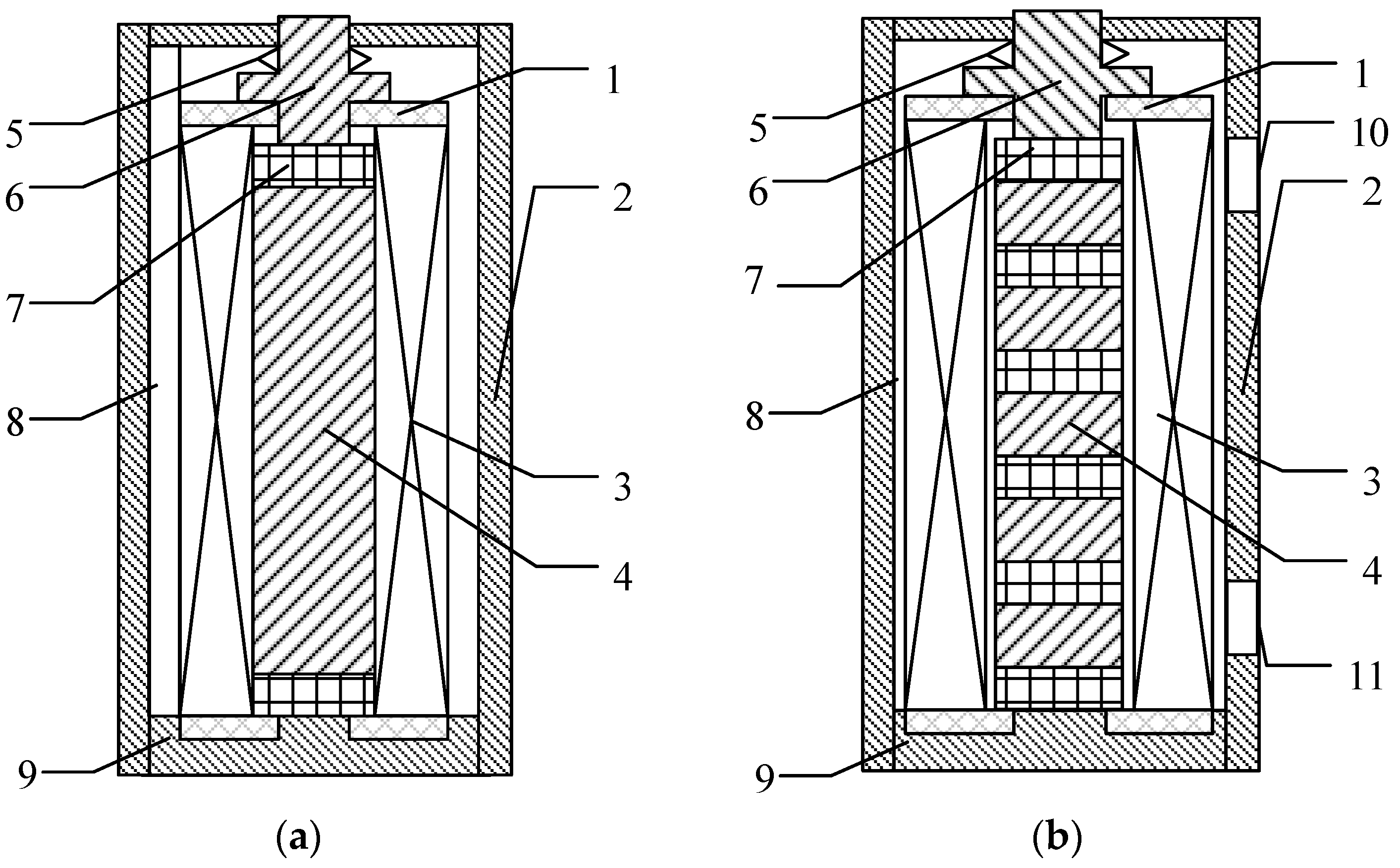
At present, in order to solve the frequency doubling effect, the GMA for the servo valve mostly adopts the magnetic biased GMA, as shown in Figure 1a. On this basis, some scholars alternately stack permanent magnets and GMM rods to form stacked GMM rods, and develop a stacked magnetic biased GMA (SGMA), as shown in Figure 1b. The SGMA improves the uniformity of the magnetic field, but in the analysis, most scholars only focus on solving the frequency doubling effect and ignore the eddy current effect and skin effect that affect the output accuracy.
A common GMA is mainly composed of a GMM rod, permanent magnets, coil, shell, ejector, and other parts. The alternating current will generate an alternating excitation magnetic field, which will generate an eddy current magnetic field inside the GMM rod. The excitation magnetic field, eddy current magnetic field, and bias magnetic field act together on the GMM rod, causing the magnetostrictive strain of the GMM rod and pushing the ejector rod to output a displacement. In addition, researchers find that the GMM rod will produce a larger output strain under a certain preload, so in a GMA, a disc spring is generally designed to provide the preload to the GMM rod.
It can be known from Figure 1 that when the material of the shell and the ejector of the GMA is selected with a low magnetic reluctance, the GMA can form an ideal closed magnetic circuit.
Most scholars [13] make the following assumptions during the magnetic field modeling phase: 1. The magnetic reluctance of the GMM is much higher than other materials such as the shell; 2. There is no air gap between all materials, or the air gap is very small. These two assumptions make the model ignore the magnetic circuit leakage and air gap leakage. In the forced oil-cooled GMA, the magnetic flux of the oil part is also ignored. This assumption is acceptable only when the GMA does not include an oil cooling system. However, when an oil cooling system is added to the GMA, a larger oil cavity will inevitably appear inside the GMA. As can be seen from reference [14], in GMA magnetic circuit modeling, the magnetic circuit law is similar to the circuit law: 1. In the magnetic circuit, the parallel magnetic segments have the same magnetomotive force; 2. In the magnetic circuit, the magnetic flux of the main circuit is the sum of the magnetic fluxes of the branches. Therefore, in the modeling of the magnetic circuit, the magnetic flux in the oil cavity should be taken into account, and the GMA cannot be simply regarded as a branchless magnetic circuit.
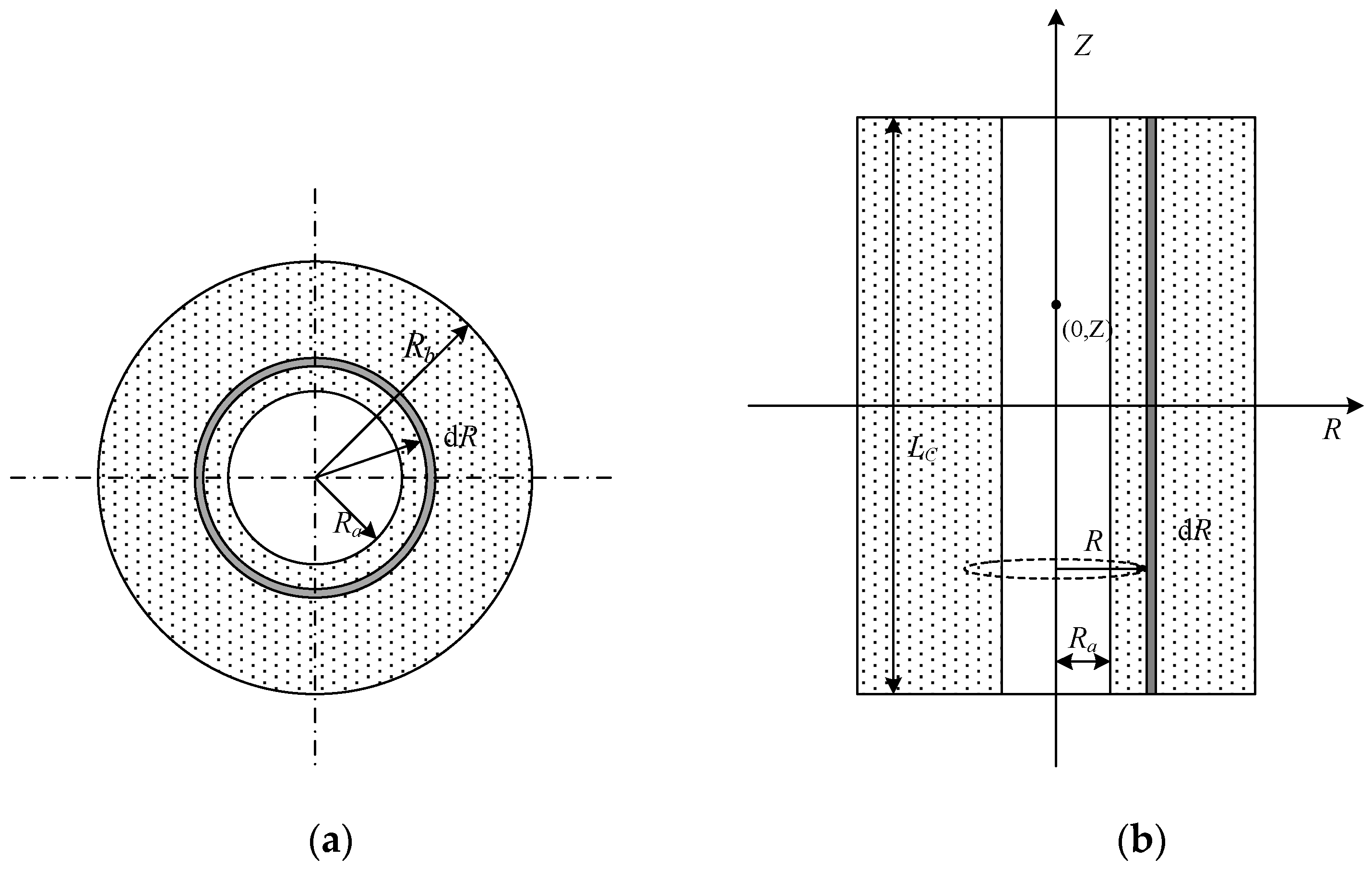
Because the structure of the GMA is axisymmetrical, its internal magnetic circuit is also symmetrical. To facilitate analysis, the GMA is cut along the axis and one side is taken for magnetic circuit analysis, as shown in Figure 2. Coils and permanent magnets work together to generate a magnetomotive force, and the magnetic flux will flow in the magnetic circuit along the sequence of the ejector ①–upper cover ⑥–shell ⑦ (oil cavity ⑧)–lower cover ⑨, where there are multiple places in series and parallel in the process.
In the SGMA, there are three sources of magnetomotive force: One is the excitation coil, the other is the permanent magnet, and the third is the eddy current magnetic field generated by the eddy current effect. When the three magnetic fields are superimposed, they act on the GMM rod together, causing the GMM rod to have a magnetostrictive effect.
The excitation magnetic field is generated by the current in the coil, and its magnetomotive force is
where N is the number of coil turns and I is the excitation current.
The magnetic field generated by the permanent magnet does not change, and its magnetomotive force U2 is a certain value, which is determined by the nature of the permanent magnet itself. In the SGMA, as the permanent magnets and GMM rods are stacked alternately, the magnetic field generated by the permanent magnets is mainly absorbed by the GMM rods, and the magnetic leakage outside the magnetic circuit is small. Therefore, the magnetomotive force of a permanent magnet is approximately equal to the product of its equivalent coercive force Hc and its length l2, that is,
The eddy current magnetic field is generally manifested as hindering the change in the excitation magnetic field, so the eddy current magnetic field is the loss when the excitation magnetic field acts on the GMM rod, that is, the eddy current magnetomotive force U3 and U1 are related. In the SGMA, it is considered that U3 only acts on GMM rods and does not affect other components in the magnetic circuit. Therefore, U3 is regarded as the loss of U1 and is not analyzed in the magnetic circuit. Thus, for the SGMA,
In the magnetic circuit, the reluctance RΩi of each component of the SGMA can be expressed as
In Equation (4), li is the length of each component (where l2 is the sum of the lengths of the permanent magnets and l3 is the sum of the lengths of the GMM rods), μi is the permeability, and Ai is the cross-sectional area.
Therefore, the total reluctance RΩ of the SGMA is
Combining Equations (1), (2), and (5), it can be obtained that the average magnetic field strength H in the trunk road is
Inside the coil, there is a gap between the GMM rod and the coil skeleton, so the average magnetic field strength HG distributed to the GMM rod and the permanent magnet can be expressed as
The structure of the excitation coil and skeleton in the SGMA is shown in Figure 3. Set the coordinate axis with the center of the coil as the origin. The coil winding length is LC, the inner radius is Ra, and the outer radius is Rb.
In Reference [14], the magnetic induction strength on the internal cross-section of the coil can be considered approximately equal everywhere. In a vacuum, the magnetic field strength excited at a point (0, Z) on the coil axis is
Therefore, in the SGMA, the magnetic field intensity distributed to the stacked GMM rods is
Through Equation (9), we establish the magnetic field model inside the SGMA and connect the input current with the magnetic field strength of the SGMA. In addition, the model describes the inhomogeneity of the internal magnetic field of the SGMA.
3. Magnetization Modeling of SGMA
When describing the relationship between the magnetic field strength and magnetization of a GMM, the Jiles–Atherton model is one of the currently used materialistic models [15]. The Jiles–Atherton model describes the obvious hysteresis and non-linear characteristics of the GMM magnetization process. From the perspective of physics, the GMM magnetization model is established in the form of calculus. In order to solve the problem where different scholars have different forms when quoting the Jiles–Atherton model, Qingyou et al. modified the Jiles–Atherton model of the plastic magnetization deformation of materials by discussing the physical meaning of different variables [16]. Guangming et al. unified the form of the Jiles–Atherton model based on the physical meaning and mathematical properties, and eliminated intermediate variables to simplify the Jiles–Atherton model [17,18].
According to Weiss molecular field theory, under the action of the external magnetic field H, the internal effective magnetic field He of the GMM is
In Equation (10), α is the molecular field parameter and M is the magnetization.
In a GMM rod, the magnetization M comprises a reversible magnetization Mrev and an irreversible magnetization Mirr, that is,
In Equation (11), the reversible magnetization Mrev is related to the irreversible magnetization Mirr and the hysteresis-free magnetization Man, that is,
In Equation (12), c is a reversible coefficient, which is determined by the characteristics of the GMM, and represents the relationship between Mrev and Mirr.
From the law of conservation of energy, the static magnetization energy in the magnetization process is the difference between the non-hysteretic magnetization static magnetic energy and the hysteresis energy loss, that is,
In Equation (13), k is a pinning coefficient, which indicates the strength of the hysteresis. δ and δM are symbolic parameters, which are defined as
From the theory of paramagnetic magnetization and the Langevin function, the non-hysteresis magnetization Man can be expressed as
In Equation (15), Ms is a saturation magnetization and a is a shape parameter.
Equations (10)–(13), and (15) give the general expressions of the Jiles–Atherton model, that is
Simplify Equation (16), remove the intermediate variables, and organize the Jiles–Atherton model into
As the relationship between M and H is given by a nonlinear ordinary differential equation, an analytical solution cannot be obtained, so we use the Runge–Kutta method to solve its numerical solution. The fourth-order Runge–kutta formula is chosen here.
Then,
In Equation (19), h is the calculation step size, and Mn and Hn are the iteration values of M and H in the nth-step calculation, respectively.
4. Output Model of SGMA
According to the quadratic moment domain rotation model, we can establish an uncoupled magnetomechanical model of the GMM. The relationship between the magnetostrictive strain λ and the magnetization M of the GMM can be expressed as
where λS is the saturation magnetostrictive strain.
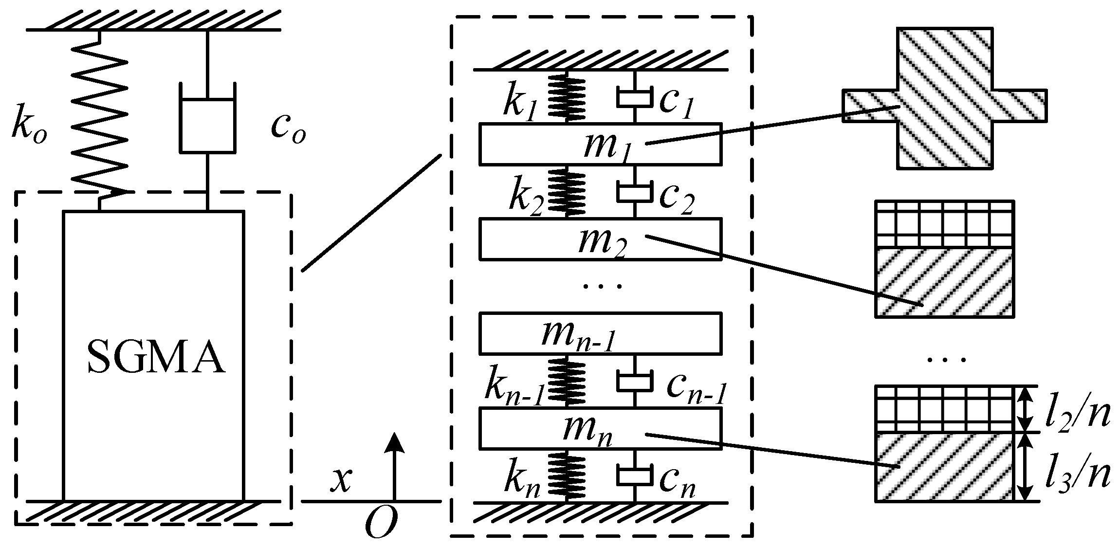
The excitation coil generates an excitation magnetic field that is not uniformly distributed on the GMM rod, and the permanent magnet reduces the unevenness of the overall magnetic field of the SGMA. However, the permanent magnet increases the discontinuity of the local magnetic field intensity change of the GMM rod, that is, the magnetic field intensity change trend in the GMM rod on both sides of the permanent magnet is different. Therefore, in the dynamic analysis of the SGMA, it cannot be regarded as a whole, and the stacked GMM rods should be equivalent to n series mass-spring-damping systems, as shown in Figure 4.
As shown in Figure 4, m1 is the mass of the output jack, and m2–mn are the sum of the mass of a small piece of permanent magnet and the GMM rod, that is,
In Equation (21), ρ1 and ρ2 are the mass densities of the permanent magnet and the GMM rod, respectively, and A2 is the cross-sectional area of the stacked GMM rod.
The multi-degree-of-freedom vibration equation is
where M, C, and K are the mass matrix, damping matrix, and stiffness matrix, respectively, and Q is the driving force vector.
Because the stacked GMM rods use homogeneous materials, and the performance of the same material in the axial direction is not much different, it can be considered that its elastic modulus and structural damping are uniform. Therefore, in a multi-degree-of-freedom model,
In Figure 4, the displacement of each element of the multi-degree-of-freedom vibration system mainly manifests as the deformation of the spring and the damper. In essence, it is the deformation of the GMM rod.
Set the average strain of the i-th stage GMM to be λi, then its magnetostrictive force is
where EN is the GMM elastic modulus.
The permanent magnet hardly generates magnetostrictive strain, so its force comes from the strain of the GMM rod on both its sides. Therefore, in a multi-degree-of-freedom vibration system, the driving force of mi is
For a SGMA, both the output force F and the output displacement x ultimately appear as the displacement and force of the ejector m1, so
Through the output model of the multi-degree-of-freedom system, we established the relationship between the magnetic field and the output displacement (and force). Although this relationship is established by a discrete model, because we only focus on the force and displacement of the ejector, a continuous output is obtained.
5. Loss Analysis of SGMA
Because of its low resistivity, a GMM has an eddy current effect in an alternating magnetic field, which will generate an eddy magnetic field. The eddy magnetic field is opposite to the excitation magnetic field, thus hindering the effect of the excitation magnetic field on the GMM rod. The eddy current magnetic field is not uniformly distributed inside the GMM rod and reaches the maximum at the center of the GMM rod, so the skin effect occurs. The effective magnetic field can reach the radial depth inside the material, and the skin depth δ can be expressed as
In Equation (27), f is the frequency of the excitation magnetic field, σ is the conductivity of the GMM, μ0 is the vacuum permeability, and μr is the relative permeability of the material.
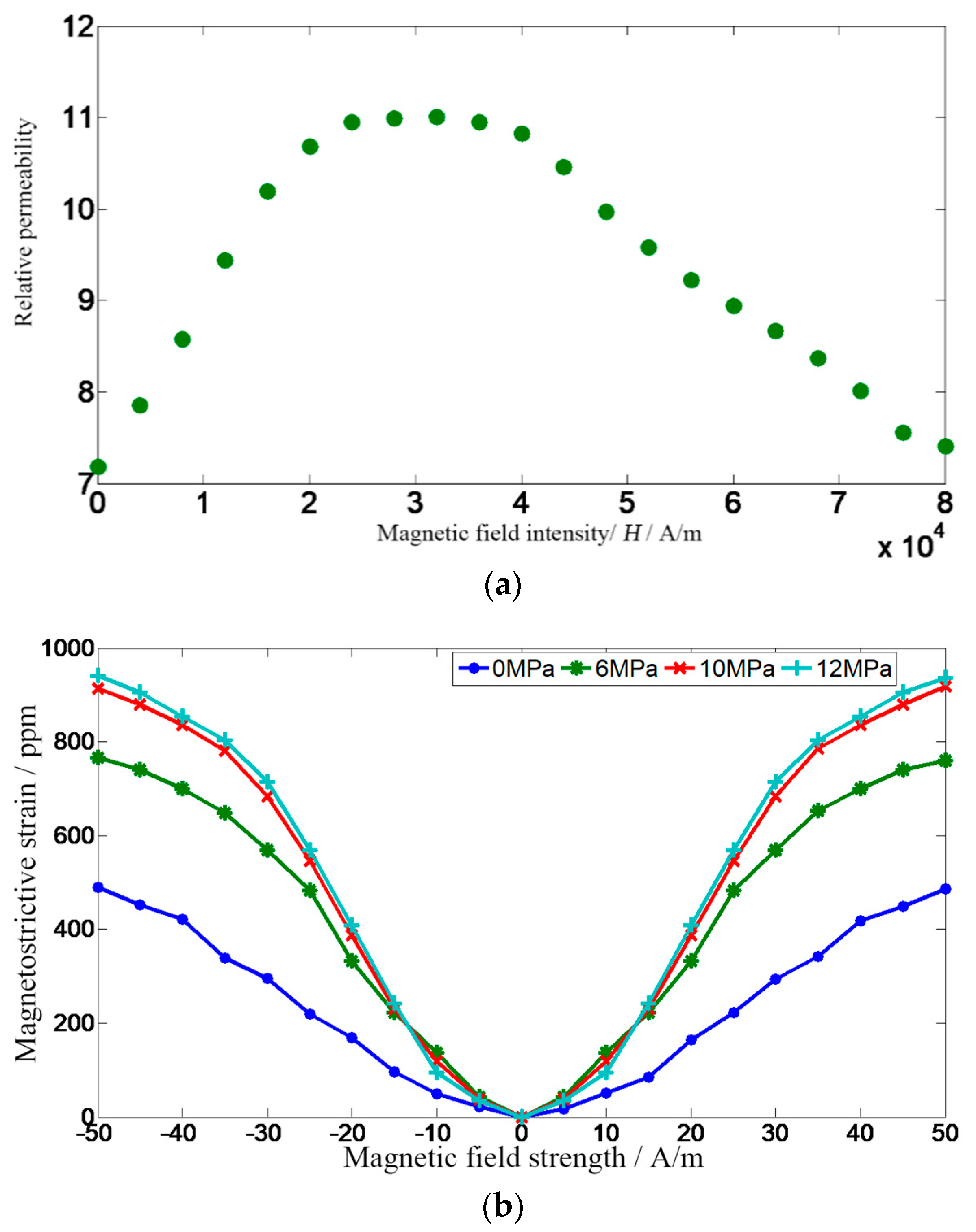
The external environment in which the GMM rod is located, mainly the magnetic field strength and the pre-stressing force, easily affects its relative permeability. The relationship between magnetostrictive strain and magnetic field strength under different prestresses is shown in Figure 5a, and the measured curve of the relative permeability of the GMM rod with the applied magnetic field strength under the preload of 10 MPa is shown in Figure 5b [19].
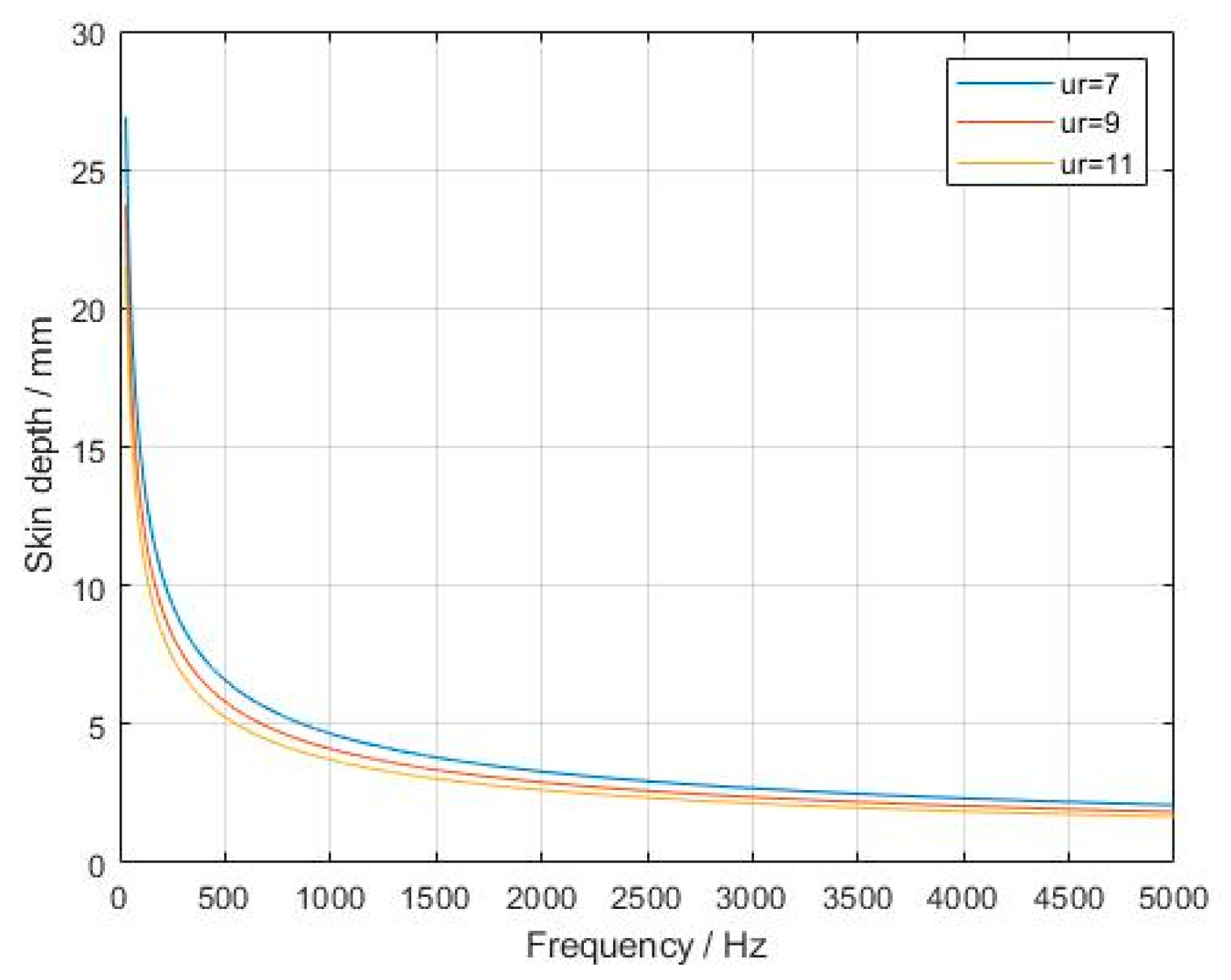
It can be seen from Figure 5 that when the magnetic field strength changes, the relative permeability of the GMM changes greatly. Taking μr = 7, 9, and 11, and the resistivity of the GMM 1/σ = 6 × 10⁻⁷ Ω·m, the skin depth is shown in Figure 6.
It can be seen from Figure 6 that the skin depth of the GMM decreases as the frequency of the applied magnetic field increases. When the frequency of the applied magnetic field reaches the order of 1000 Hz, the skin depth of the GMM rod is less than 5 mm, which seriously affects the magnetization effect of the GMM rod and the output accuracy of the SGMA.
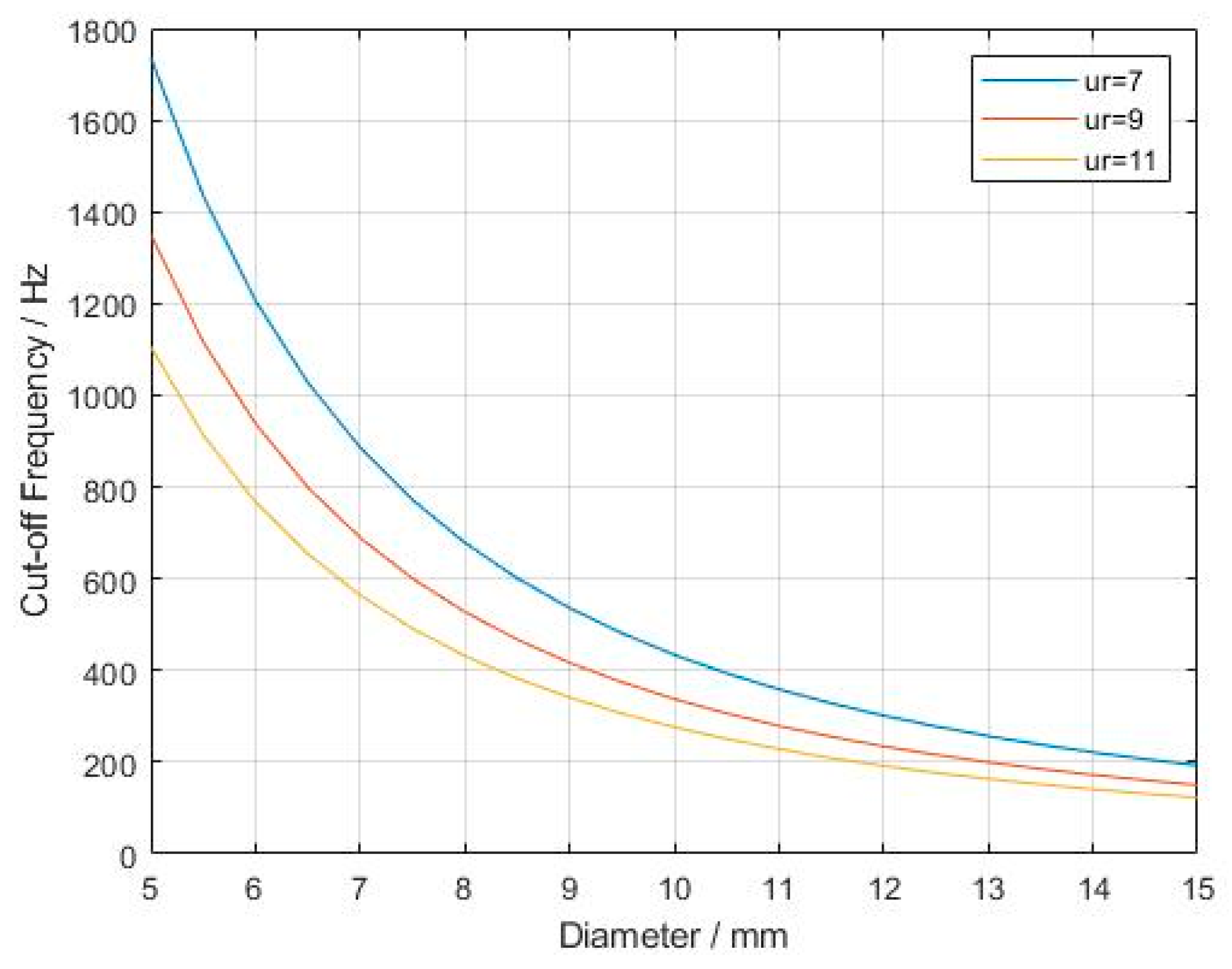
Another key parameter of the GMM is the eddy current cutoff frequency, which is the minimum frequency at which the skin effect can be ignored. This frequency is expressed as [20]
In Equation (28), d = 2r is the diameter of the GMM rod. Selecting the same parameter settings as in Figure 6, we obtain the relationship between the diameter of the GMM rod and the eddy current cutoff frequency, as shown in Figure 7.
Among different magnetic materials, when the operating frequency is the same, the lower the eddy current cut-off frequency fc, the greater the eddy current loss. It can be seen from Figure 7 that the diameter of the GMM has a significant negative correlation with the cutoff frequency of the material, and in the large-diameter GMM rod, the eddy current effect has a great influence. When the diameter of the GMM reaches 10 mm, the upper limit frequency of the applied magnetic field is less than 500 Hz, which severely limits the response speed of the SGMA.
Known from Maxwell’s equations,
In Equation (29), H is the magnetic field strength, J is the current density, E is the electric field strength, B is the magnetic induction strength, and σ is the conductivity.
From Equation (29), the propagation formula of H can be obtained
For rod-shaped GMM materials, take any point inside it, and set the distance from this point to the axis of the GMM rod as x. At time t, when the external magnetic field , the internal magnetic field of the GMM rod can be expressed as
where .
Considering Equation (31) as the zero-order Bessel function of the imaginary argument, combined with the Kelvin function, the solution can be expressed as [21]
where J0 is the Bessel function of the first kind, , and
Ber is the real part of the Kelvin function, Bei is the imaginary part of the Kelvin function, and .
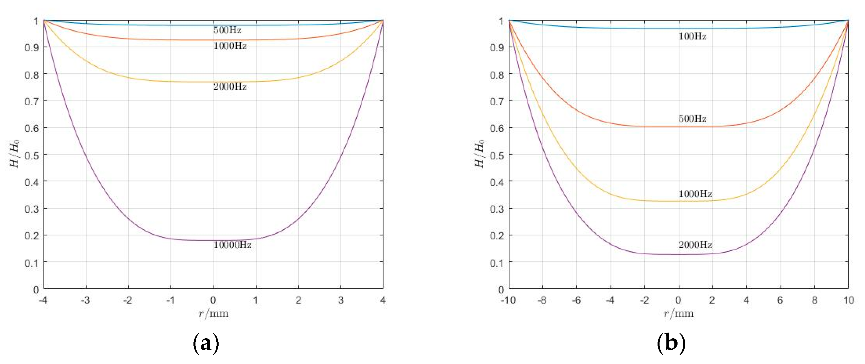
Take the parameters of the SGMA as follows: GMM resistivity 1/σ = 6 × 10⁻⁷ Ω·m; relative permeability μr = 11; radius r = 4, 10 mm; frequencies are 100, 500, 1000, 2000, or 10,000 Hz. According to Equation (32), the internal magnetic field strength of the GMM rod is shown in Figure 8.
It can be known from Figure 8 that when the frequency of the applied magnetic field increases, the relative magnetic field strength of the GMM rod decreases, that is, there is a part in the GMM that cannot be completely penetrated by the magnetic field, and the closer to the center of the rod, the greater the attenuation of the magnetic field. Moreover, GMM rods with different rod diameters have different blocking effects on high-frequency magnetic fields. The thicker the GMM rod (i.e., the larger the radius), the stronger the attenuation at the same frequency.
When the GMM rod is in an alternating magnetic field, due to the eddy current effect, the induced electromotive force generated in the rod can be expressed as
The internal resistance of the GMM rod can be expressed as
Therefore, the eddy current loss of the GMM is
In the alternating magnetic field, due to the inherent hysteresis effect of the GMM, the magnetic induction intensity will be one phase φ behind the applied magnetic field, that is,
Therefore, the permeability of the GMM in an alternating magnetic field can be expressed as
where
Due to the imaginary part of the relative permeability, the GMM also has hysteresis loss in the applied alternating magnetic field. The loss per unit time can be expressed as
Simplified,
From Equations (37) and (39), we can know that the hysteresis loss of the GMM is
The impedance of the coil is
Then, under the alternating current, the heat loss of the coil is
where is the coil impedance and Rct is the coil resistance.
From Equations (35), (39), and (43), the total loss p in the SGMA is
The output model describes the process of converting electrical energy into mechanical energy, and the loss model describes the process of converting electrical energy into internal energy. These two processes occur at the same time. Of course, changes in internal energy will also cause changes in material properties, so we need to reduce the conversion of electrical energy into internal energy or reduce the impact of internal energy on output.
6. Design of the Cooling System
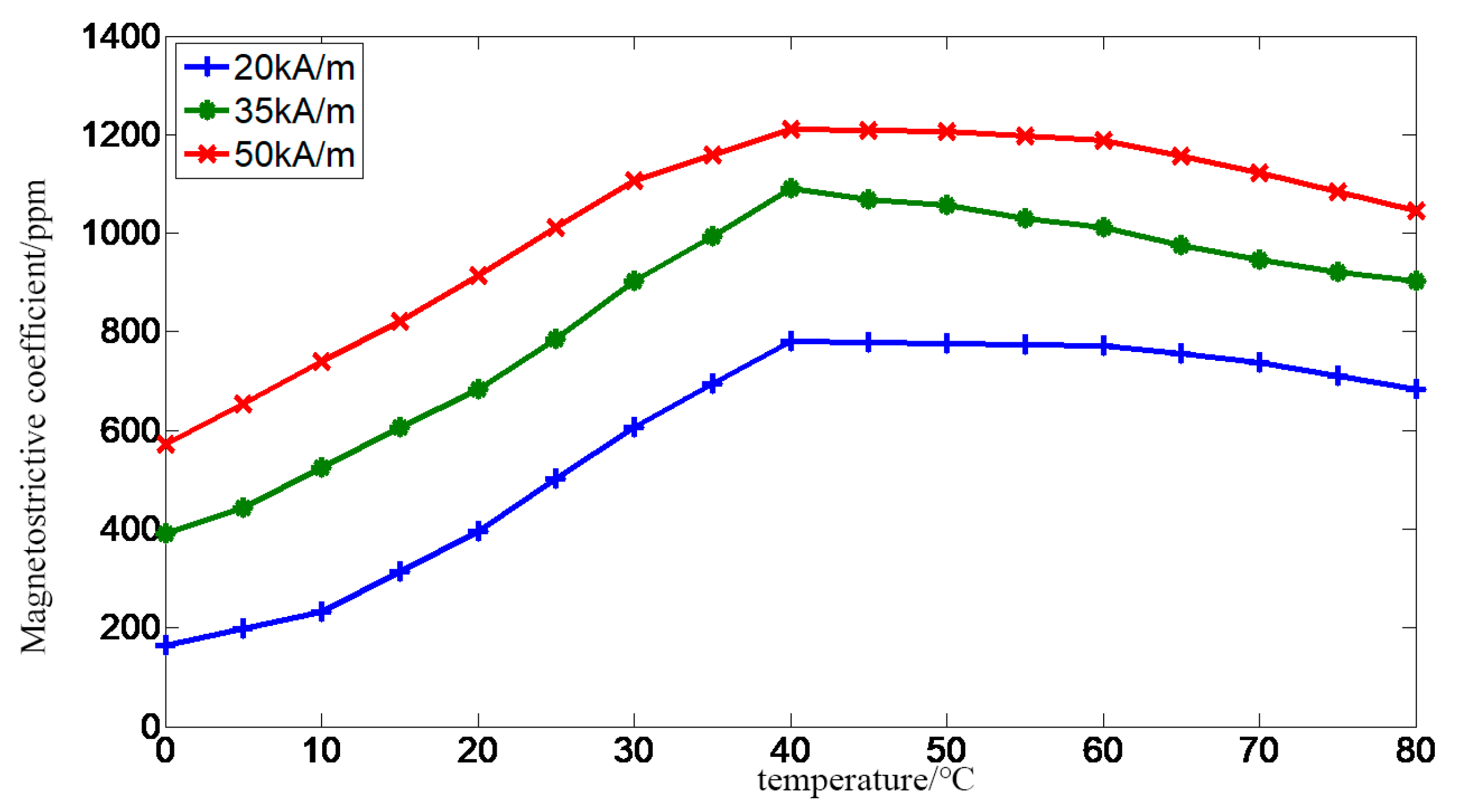
There is a large loss in the SGMA, and a large amount of energy is converted into internal energy. Due to the compact structure of the SGMA itself, internal energy is generated inside the SGMA and the heat exchange with the outside is not smooth. Therefore, the internal energy generated by the loss cannot be lost in time. A large amount of internal energy can accumulate inside the SGMA, causing its temperature rise. In addition, the GMM is a heat-sensitive material, so when the temperature changes, the GMM magnetostrictive strain is as shown in Figure 9.
It can be seen from Figure 9 that when the temperature changes, the magnetostrictive strain value of the GMM changes greatly.
In addition, a sharp rise in the internal temperature of the SGMA will also cause thermal expansion of the GMM rod. When the temperature changes, the thermal deformation of the GMM is
where is the linear expansion coefficient of the GMM, l is the length of the GMM rod, and is the temperature change.
Therefore, temperature has a great influence on the SGMA. In the modeling of the SGMA, the influence of temperature must be considered. However, the heating source, heating mechanism, and heat exchange process in the SGMA are relatively complicated. When applying the non-steady-state heat conduction differential equation and Fourier’s theorem, many parameters are not easy to obtain accurately, so we use a simplified design method [23].
From the SGMA itself, in order to suppress the effect of temperature changes on its output, known from Figure 9, it should be stabilized to work at about 40 °C. Therefore, in the design process, the parameters that need attention are only the size of the SGMA and the flow rate of the cooling oil. The size parameters of the SGMA are determined by its output characteristics, and it is only necessary to pay attention to the flow rate of the cooling oil in terms of temperature characteristics.
Assume that, in a SGMA, the heat transferred from the surface of each component is proportional to its surface area. According to the principle of pyrology, the flow rate of cooling oil is at least
where c is the specific heat capacity of the cooling oil.
7. Experimental Verification of Oil-Cooled SGMA
According to the foregoing analysis, the prototype parameters of the SGMA are as Table 1:
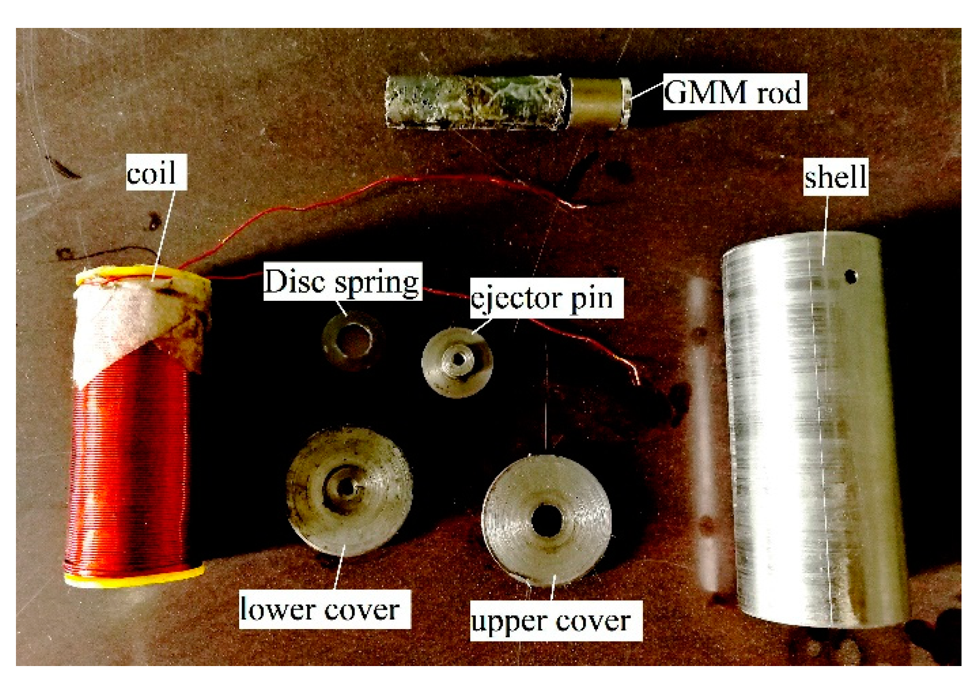
The prototype of the SGMA is shown in Figure 10.
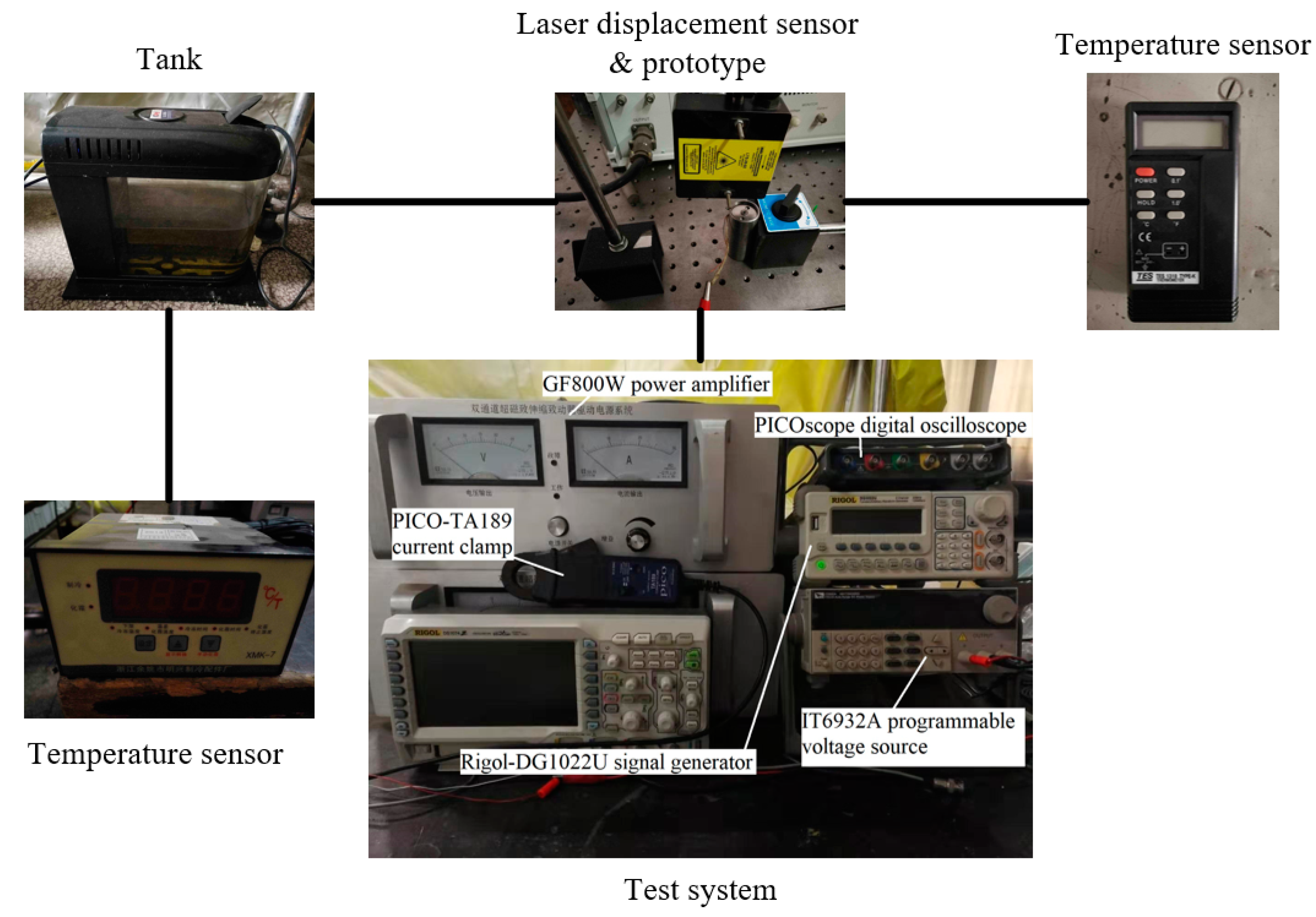
In order to test the relevant performance of the SGMA prototype, we set-up a SGMA test system, as shown in Figure 11.
The test system uses the Rigol-DG1022U signal generator (Shenzhen Keruijie Technology Co., Ltd., Shenzhen, China) to generate the excitation signal, which is amplified by the GF800W power amplifier to drive the SGMA. The cooling oil is pumped into the SGMA by an oil pump to stabilize the temperature of the SGMA. The IT6932A programmable voltage source provides MicrotrakTM 3-LTS-025-02 laser (MTI Instruments, Inc., Washington, USA) displacement sensor power, so that the laser displacement sensor can accurately measure the displacement of the SGMA. The system uses the TES-1310 temperature sensor (TES Electrical Electronic Corp., Taiwan, China) to monitor the actuator temperature, the XMK-7 temperature sensor (Mingxing Refrigeration Parts Factory, Yuyao, China) to monitor the fuel tank oil temperature, the PICO-TA189 current clamp (PicoTechnology Inc, Cambridgeshire, UK) to monitor the input current value, and the PICOscope digital oscilloscope to collect test data. The cooling system is shown in Figure 12.
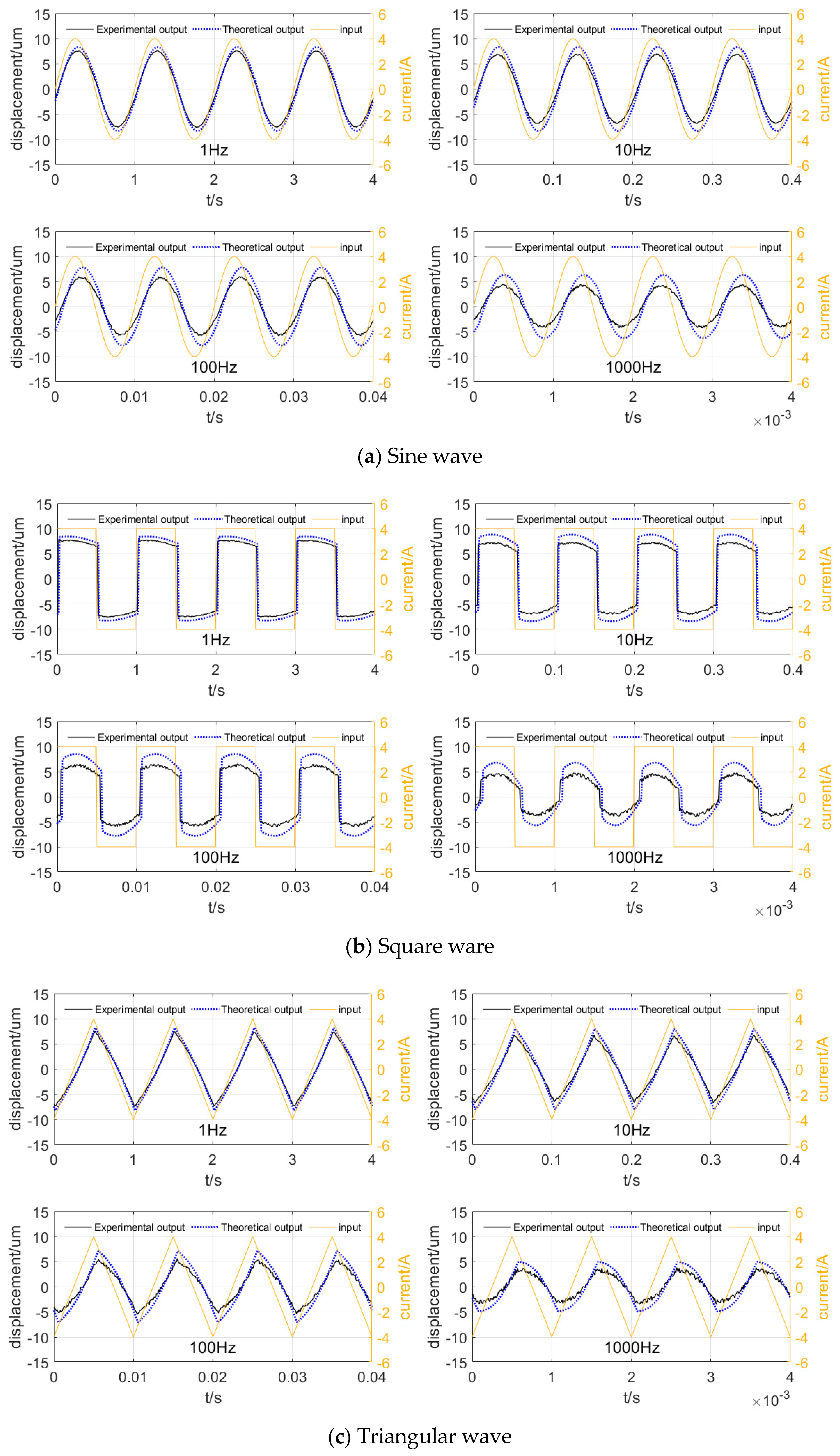
Pass a 1, 10, 100, and 1000 Hz sine wave, square wave, and triangular wave through the SGMA. The corresponding experimental results are as follows:
It can be seen from Figure 13 that the SGMA responds well to signals of different waveforms, but due to the influence of the response speed of the coil and the nature of the material itself, the displacement waveform has a deviation compared to the input waveform.
The output waveform has a lag relative to the input, and as the excitation frequency increases, the lag phase difference increases. In addition, the output displacement of the SGMA decreases with increasing frequency. On the waveform, the experimental results are similar to the theoretical calculation results, and the phase difference between them is small, indicating that the modeling theory can be used to describe the principle of the SGMA. As the frequency increases, the error between the theoretical and experimental results increases, and the loss from the actual output is significantly greater than the theoretical calculation, showing that the modeling theory does not accurately describe the high-frequency motion of the SGMA. This is because the calculation of high-frequency loss in the output modeling theory mainly comes from the J–A model, and does not consider the case of incomplete magnetization of the GMM rod due to the eddy current and skin effect under high-frequency action.
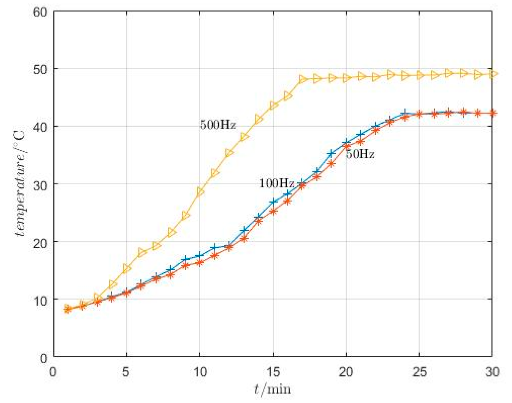
Sine waves of 50, 100, and 500 Hz are passed into the SGMA, and the internal temperature change of the SGMA is monitored by a temperature sensor. The results are shown in Figure 14.
It can be seen from Figure 14 that when cooling oil is introduced into the SGMA, the internal temperature of the SGMA slowly rises and remains stable after reaching a certain temperature, but the stable temperature is different at different frequencies, and the higher the frequency, the higher the temperature. The experimental results show that the cooling system can indeed keep the temperature of the SGMA stable and restrain the thermal deformation of the material and the change in the magnetostrictive coefficient caused by the temperature.
8. Conclusions
This paper analyzes the magnetic field distribution of a stacked giant magnetostrictive actuator, and it establishes the magnetization model and output model of a SGMA, analyzes various losses occurring in the work of the SGMA, and designs the cooling system of the SGMA. Based on theoretical analysis, we make a prototype of the SGMA, build a corresponding test system, conduct related experiments, and obtain the following conclusions:
- Inside the SGMA, the magnetic field distribution is not uniform. Due to the existence of the cooling oil cavity, there are multiple series and parallel situations in the magnetic circuit, and the magnetic field generated by the excitation coil cannot be completely concentrated on the GMM rod.
- On the GMM rod, the magnetic field distribution is also not uniform. In the axial direction, the distribution of the magnetic field on the GMM rod is related to its axial coordinates, and in the radial direction, it is related to its radius and the frequency of the applied magnetic field.
- There are various losses in the SGMA, including eddy current loss, hysteresis loss, and coil loss. These three losses cause a large amount of energy to be dissipated as internal energy and affect the output accuracy of the SGMA.
- Considering the loss of heat generation, in order to reduce the influence of temperature on accuracy, this paper designs a SGMA cooling system. Through analysis, this paper uses a simplified calculation method and obtains the fact that the flow rate of the cooling oil is related to the size and loss of SGMA.
- In this paper, a complete modeling theory of SGMA is established, and all theoretical models from current to output and loss are obtained. Not only the output but also the loss are analyzed, and an active temperature control method is proposed. The SGMA designed in this paper has a fast response speed, stable output waveform, and small error under the conditions of laboratory and low-frequency excitation signals. When the cooling system is installed, the temperature rise of the SGMA can be effectively controlled, which can meet the application requirements of direct-drive electro-hydraulic servo valves.
Author Contributions
Conceptualization, Z.H.; methodology, J.Z. (Jiawei Zheng) and G.L.; software, G.B. and J.Z. (Jingtao Zhou); formal analysis, G.L.; data curation, G.L., G.B. and B.D.; writing—original draft preparation, G.L.; project administration, Z.H. All authors have read and agreed to the published version of the manuscript.
Funding
This work is supported by the National Natural Science Foundation of China (No. 51,275,525).
Conflicts of Interest
The authors declare no conflict of interest.
References
- Clark, A.E.; Lindgren, E.A. Development of Terfenol-D transducer material. J. Appl. Phys. 1998, 83, 7282–7284. [Google Scholar]
- Engdahl, G. Simulation of the magnetostrictive performance of Terfenol-D in mechanical devices. J. Appl. Phys. 1988, 63, 3924–3926. [Google Scholar] [CrossRef]
- Apicella, V.; Clemente, C.S.; Davino, D.; Leone, D.; Visone, C. Review of modeling and control of magnetostrictive actuators. Actuators 2019, 8, 45. [Google Scholar] [CrossRef] [Green Version]
- Karunanidhi, S.; Singaperumal, M. Design, analysis and simulation of magnetostrictive actuator and its application to high dynamic servo valve. Sens. Actuators A Phys. 2010, 157, 185–197. [Google Scholar] [CrossRef]
- Claeyssen, F.; Lhermet, N.; Letty, L. Actuators, transducers and motors based on giant magnetostrictive materials. J. Alloys Compd. 1997, 258, 61–73. [Google Scholar] [CrossRef]
- Tiberg, H.; Engdahl, G.; Bergqvist, A.; Kvarnsjo, L. A method of computing electro-mechanical transfer functions for magnetostrictive functional units. IEEE Trans. Magn. 1992, 28, 2808–2810. [Google Scholar] [CrossRef]
- Tiberg, H.; Bergqvist, A.; Engdahl, G. Evaluation of a magnetostrictive drive element model. J. Appl. Phys. 1993, 73, 5851–5853. [Google Scholar] [CrossRef]
- Kvarnsjo, L.; Engdahl, G. Nonlinear 2-D transient modeling of Terfenol-D rods. IEEE Trans. Magn. 1991, 27, 5349–5351. [Google Scholar] [CrossRef]
- Goodfriend, M.; Sewell, J. Application of a magnetostrictive alloy, terfenol-d to direct control. SAE Int. Off Highw. Powerpl. Congr. Exhib. 1990, 10–13. [Google Scholar] [CrossRef]
- Goodfrend, M. Material breakthrough spurs actuator design. Mach. Des. 1991, 63, 147–150. [Google Scholar]
- Urai, T.; Tanaka, H. Development of a giant magnetostrictive actuator and the application to a servo valve. Trans. Jpn. Hydraul. Pneum. Soc. 2001, 32, 53–57. [Google Scholar]
- Li, L.; Zhang, C.; Yan, B.; Xiaopeng, L. Research of a giant magnetostrictive value with internal cooling structure. IEEE Trans. Magn. 2011, 47, 2897–2900. [Google Scholar] [CrossRef]
- Clemente, C.S.; Davino, D. Modeling and characterization of a kinetic energy harvesting device based on galfenol. Materials 2019, 12, 3199. [Google Scholar] [CrossRef] [PubMed] [Green Version]
- Xue, G.; Zhang, P.; He, Z.; Xin, L.; Wei, Z.; Yang, C. Revised reluctance model of the axial magnetic field intensity within giant magnetostrictive rod. Proc. IMechE Part C J. Mech. Eng. Sci. 2017, 231, 2718–2729. [Google Scholar]
- Jiles, D.C.; Atherton, D.L. Theory of ferromagnetic hysteresis. J. Magn. Magn. Mater. 1986, 61, 48–53. [Google Scholar] [CrossRef]
- Qing-You, L.; Xu, L.; Zhu, H.; Han, Y.; Liu, J. Modeling plastic deformation effect on the hysteresis loops of ferromagnetic materials based on modified Jiles-Atherton model. Acta Phys. Sin. 2017, 66, 107501. [Google Scholar]
- Xue, G.; Zhang, P.; He, Z.; Li, D.; Yang, Z.; Zhao, Z. Modification and numerical method for the Jiles-Atherton hysteresis model. Commun. Comput. Phys. 2017, 21, 763–781. [Google Scholar] [CrossRef]
- Xue, G.; Zhang, P.; He, Z.; Li, D. Approximation of anhysteretic magnetization and fast solving method for Jiles-Atherton hysteresis equation. Ferroelectrics 2016, 502, 197–209. [Google Scholar] [CrossRef]
- He, Z.; Rong, C.; Li, D.; Xue, G.; Zheng, J. Modeling and analysis of magnetic field distribution of stacked giant magnetostrictive actuators. Opt. Precis. Eng. 2017, 25, 2347–2358. [Google Scholar]
- Engdahl, G. Handbook of Giant Magnetostrictive Materials; Academic Press: San Diego, CA, USA, 2000. [Google Scholar]
- Sun, H.; Yuan, H. Theoretical analysis of magnetic field and eddy current loss within giant magnetostrictive material. J. Northeastern Univ. (Nat. Sci.) 2008, 29, 371–374. [Google Scholar]
- Raghavendra, A. High Frequency High Amplitude Magnetic Field Driving System for Magnetostrictive Actuators; University of Maryland: College Park, MD, USA, 2009. [Google Scholar]
- Jia, Z.; Yang, X.; Guo, D.; Hou, L. Theories and methods of designing micro-displacement actuator based on giant magnetostrictive materials. Chin. J. Mech. Eng. 2001, 37. [Google Scholar] [CrossRef]
Figure 1.
Giant magnetostrictive actuator (GMA): (a) Non-stacked, (b) stacked. 1. Coil skeleton; 2. Shell; 3. Coil; 4. Giant magnetostrictive material (GMM) rod; 5. Preloaded disc spring; 6. Ejector; 7. Permanent magnet; 8. Oil cavity; 9 End cap; 10. Cooling oil inlet; 11. Cooling oil outlet.
Figure 1.
Giant magnetostrictive actuator (GMA): (a) Non-stacked, (b) stacked. 1. Coil skeleton; 2. Shell; 3. Coil; 4. Giant magnetostrictive material (GMM) rod; 5. Preloaded disc spring; 6. Ejector; 7. Permanent magnet; 8. Oil cavity; 9 End cap; 10. Cooling oil inlet; 11. Cooling oil outlet.

Figure 2.
Magnetic circuit model of stacked giant magnetostrictive actuator (SGMA): (a) Sectional view of one side of SGMA, (b) magnetic circuit model. 1. Ejector; 2. Permanent magnet; 3. GMM rod; 4. Coil; 5. Inner oil cavity; 6. Upper cover; 7. Shell; 8. Outer oil cavity; 9. Lower cover; 10. Preloaded disc spring.

Figure 3.
Coil skeleton: (a) Top view, (b) front view.

Figure 4.
Multi-degree-of-freedom vibration system.

Figure 5.
(a) Relative permeability of GMM and magnetic field strength. (b) Magnetostrictive strain of GMM and magnetic field strength.
Figure 5.
(a) Relative permeability of GMM and magnetic field strength. (b) Magnetostrictive strain of GMM and magnetic field strength.

Figure 6.
Skin depth of GMM rods at different relative permeabilities.

Figure 7.
Relationship between GMM rod diameter and eddy current cutoff frequency.

Figure 8.
Magnetic field intensity distribution inside the GMM rod. (a) r = 4 mm, (b) r = 10 mm.

Figure 9.
Relationship between giant magnetostrictive coefficient and temperature.

Figure 10.
Prototype of SGMA.

Figure 11.
Test system of SGMA prototype.

Figure 12.
The cooling system.

Figure 13.
Results of SGMA output experiment.

Figure 14.
Temperature experiment of SGMA.


Table 1.
The parameters of SGMA prototype.
| Parameter | Symbol/unit | Value |
|---|---|---|
| Number of segments for stacked GMM rods | n | 3 |
| GMM | Terfenol-D | |
| Diameter of stacked GMM rods | d/mm | 8 |
| Inner radius of drive coil | Ra/mm | 5 |
| Outer radius of drive coil | Rb/mm | 6 |
| Length of drive coil | LC/mm | 45 |
| Total length of all GMM rods | l2/mm | 30 |
| Total length of all permanent magnets | l3/mm | 15 |
| Number of coil turns | N | 500 |
| Magnetostrictive coefficient of GMM | 10−6 ppm | ≥1000 |
| Differential permeability of GMM | 3–15 | |
| Thermal expansion coefficient of GMM | /10−6 °C | 8–12 |
| Young’s modulus of GMM | /1010 N·m−2 | 2.5–6.5 |
| Prestress of GMM rods | /MPa | 10 |
| Specific heat capacity of cooling oil | c/kJ/(kg·K) | 0.7–0.8 |
| Density of cooling oil | /g/cm3 | 0.857 |
| Thermal conductivity of cooling oil | /W/mc | 0.11 |
| Flow rate of cooling oil | q/mL/s | 15 |
| The diameter of the wire | /mm | 1.20 |
© 2020 by the authors. Licensee MDPI, Basel, Switzerland. This article is an open access article distributed under the terms and conditions of the Creative Commons Attribution (CC BY) license (http://creativecommons.org/licenses/by/4.0/).
Share and Cite
MDPI and ACS Style
Liu, G.; He, Z.; Bai, G.; Zheng, J.; Zhou, J.; Dai, B. Modeling and Experimental Study of Oil-Cooled Stacked Giant Magnetostrictive Actuator for Servo Valve. Actuators 2020, 9, 37. https://doi.org/10.3390/act9020037
AMA Style
Liu G, He Z, Bai G, Zheng J, Zhou J, Dai B. Modeling and Experimental Study of Oil-Cooled Stacked Giant Magnetostrictive Actuator for Servo Valve. Actuators. 2020; 9(2):37. https://doi.org/10.3390/act9020037
Chicago/Turabian StyleLiu, Guoping, Zhongbo He, Guo Bai, Jiawei Zheng, Jingtao Zhou, and Bowen Dai. 2020. "Modeling and Experimental Study of Oil-Cooled Stacked Giant Magnetostrictive Actuator for Servo Valve" Actuators 9, no. 2: 37. https://doi.org/10.3390/act9020037
Note that from the first issue of 2016, this journal uses article numbers instead of page numbers. See further details here.