
A 1-DOF Modular Robotic Hand Inspired by Human Two-Arm Cooperative Handling Strategy

1
School of Mechanical and Electronic Engineering, Nanjing Forestry University, Nanjing 210037, China
2
School of Aeronautics and Mechanical Engineering, Changzhou Institute of Technology, Changzhou 213032, China
*
Author to whom correspondence should be addressed.
Actuators 2023, 12(4), 151; https://doi.org/10.3390/act12040151
Submission received: 17 February 2023
/
Revised: 14 March 2023
/
Accepted: 28 March 2023
/
Published: 31 March 2023
(This article belongs to the Section Actuators for Robotics)
Abstract
:In the present article, a 1-DOF modular robotic hand inspired by a human two-arm cooperative handling strategy was presented to achieve flexible applications in robotic object grasping. The presented modular robotic hand was characterized as 1-DOF, modular, symmetrically designed and partly soft. The soft finger could produce independent elastic deformation and adapt to the object surface passively without the additional requirement of control. The modular hand is based on bus control technology, and up to 254 modular hands can be controlled simultaneously. The above characteristic of the modular hand could greatly improve the application flexibility of the robotic end-effector. The modularity of the robotic hand makes the multi-hand cooperative operation possible, which is a potential technology to eliminate the position error of the object. Based on the modular hand, a double-hand and quadruple-hand end-effector was developed, and some experimental tests were performed to verify its versatility and operating performance. The operating stability was also verified by kinematic modeling and numerical simulation.
1. Introduction
The robotic gripper is a fundamental component of the robot that can achieve grasping operations and has wide applications in agricultural picking [1,2,3], food packing [4,5,6,7,8], and minimally invasive surgery [9,10,11,12]. For a robotic gripper, grasping generality, safety, adaptability, simplicity and affordability are essential requirements of a robotic gripper [13]. Keeping in mind the above requirements, this article presents a 1-DOF modular robotic hand, which is inspired by a human two-arm cooperative handling strategy. The aim is to achieve flexible applications in robotic grasping.
Humans can hold some small size and light objects with only one hand. However, for some larger size objects, humans need two arms to handle the object cooperatively. This is because both the dimension and weight may be out of the grasping range of a single hand under some circumstances. Therefore, some two-arm cooperative robots were developed, such as the famous Atlas and Yumi [14]. The essence of the two-arm cooperative is that the spatial position and posture of the human hand could be adjusted in a relatively large range. Through a two-arm cooperative, humans could adjust their hands’ spatial position and posture to achieve an optimal object-grasping state. For a relatively light box, humans could handle it by clamping both sides. For a relatively heavy box, humans could handle it by holding its bottom. The main difference between the above two objects grasping strategies is that human hands have different spatial positions and postures.
Inspired by the human two-arm cooperative handling strategy, we presented a 1-DOF modular robotic hand that featured as a 1-DOF, modular, symmetrically designed and partly soft. Since the robotic hand is modular, its number, spatial position, and posture are all adjustable in practical applications; in this way, grasping flexibility could be greatly enhanced. Using the modular robotic hand, engineers could develop an object-grasping scheme according to the actual requirements rapidly and flexibly. The contribution of our work includes three aspects:
(1) Modular design and bus control. In previous studies, the robotic gripper was designed in an integrated manner, such as [15,16,17]. This kind of design has the drawback of complex wiring. Under some extreme environments, complex wiring could lead to the risk of stability [18,19,20,21]. To address this problem, the proposed robotic hand was modular designed, which could be utilized to develop a complex grasping system in a more flexible and rapid manner. Each robotic hand could be controlled by the bus, which had the advantage of reducing additional electrical cables and system complexity.
(2) Partly soft. In recent years, a lot of soft grippers have been developed, and some excellent demos are referred to in [22,23,24,25,26]. Due to the inherent nonlinearity of the viscoelastic rubber material of the soft robotic gripper, its grasping process could exhibit a hysteresis characteristic, which could lead to the control of nonlinearity and large errors [27,28,29]. In the proposed robotic gripper, the robotic hand is partly soft. The finger structure is fabricated utilizing rubber to enhance its adaptability, and the actuator of the finger structure is rigid. In this way, the motion of the finger mechanism could be controlled accurately. Due to the above characteristics, multi-hand cooperative grasping could be achieved. In multi-hand cooperative grasping, the robotic gripper becomes a typical parallel structure, which is an effective approach for enhancing its grasping ability [30,31].
(3) A kinematic model of the modular hand has been developed. To support the simulation and the subsequent design of the robotic gripper, the kinematic model of a modular hand has been developed and validated experimentally.
The rest of the article is as follows: after the introduction, the structure design of the modular hand and application schemes are introduced in Section 2. Then the kinematic model of the modular hand is established in Section 3. In Section 4, some experimental tests and kinematic simulations are performed to verify the feasibility and versatility of the presented modular hand. Conclusions are given at the end.
2. Structure Design
2.1. Design of the Modular Hand
In designing the modular hand, we took into consideration the requirements of grasping generality, safety, adaptability, simplicity and affordability.
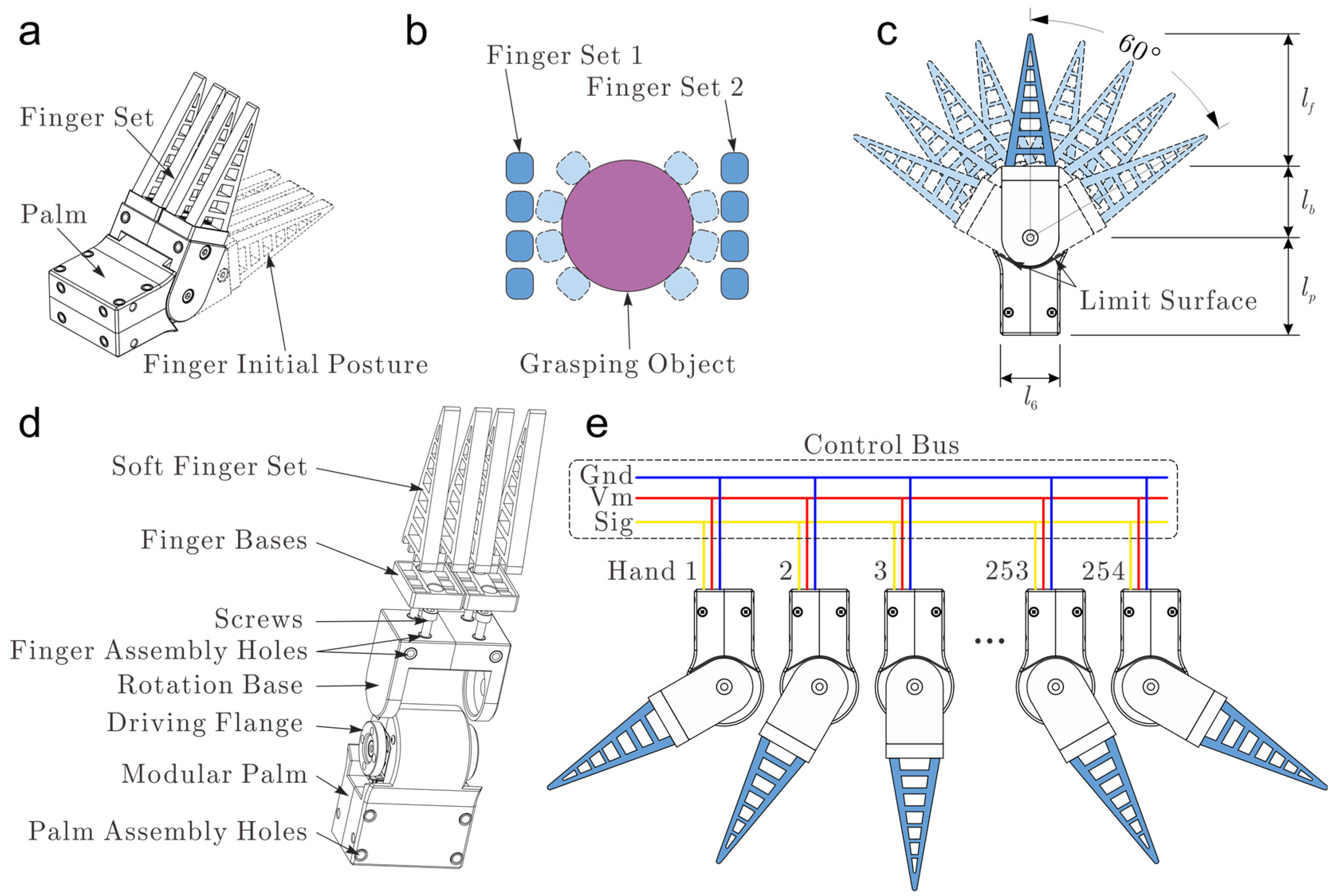
We took in mind the control simplicity, and the overall modular robotic hand was designed as two main parts, including the palm and finger parts, as shown in Figure 1a. Where the dotted line denotes the initial posture of the modular hand. The finger set could rotate with respect to the palm, and this rotation is actuated by a micro servo motor which is embedded in the palm. The modular hand only has one degree of freedom. Therefore, its motion control complexity could be greatly reduced.
The hand is modularly and symmetrically designed to achieve generality and application flexibility. As shown in Figure 1c, both the mechanical structure and motion range is symmetrical. The finger set has a one-side rotation range of 60°, and the total rotation range is 120°. The advantages of the symmetrical design are the following. The symmetric structure enables the modular hand to be installed in the frame in a more flexible manner. The resulting installation difference could be eliminated by control software easily since the motion range of the finger set is also symmetric. Figure 1d displays the details of the mechanical design of the modular hand. The modular hand could be installed on a frame by four palm assembly holes distributed on each side of the palm structure. On the rotation base, there are some pre-designed finger assembly holes to install the finger base. The soft finger set is connected to the rotating base through the finger base and four screws. In the presented design, the soft finger set is also modular and replaceable. In grasping applications, engineers could also create some specialized fingers to install on the rotating base to meet the actual requirements.
Bearing in mind safety and adaptability, the modular hand was designed as partly soft; that is, the palm structure is rigid, while the finger part was designed as soft. Due to the inherent compliance of the soft material, the hand could guarantee safe and nondestructive grasping. This feature makes the modular hand extremely suitable for daily life and agricultural picking applications. As shown in Figure 1a, the finger part is designed as a finger set, which includes four soft sub-fingers. The sub-finger design is based on the Fin Ray Effect®, which enables the finger to adapt to the object surface passively and produce an envelope effect without additional control requirements. In object grasping, the four soft sub-fingers could deform and adapt to the object surface independently when the finger set rotates, as shown in Figure 1b.
To improve the affordability of the modular hand, bus control technology was adopted. A bus-controlled micro servo motor was embedded in the palm to actuate the rotating base through a driving flange. The maximum output torque of the micro servo motor was 13 kg/cm. Using bus control technology, up to 254 motors could be controlled simultaneously. As shown in Figure 1e, the control bus contains three wires: Vm, Gnd and Sig wires. The Vm and Gnd wires supply the energy to the servo motor, and the Sig wire transfers the motion control instructions. Each robotic hand was actuated by a micro servo motor, which was embedded in the palm structure. The motion of the servo motor could be controlled by giving a motion control instruction through the control bus. For more details about the micro servo motor control, refer to our previous work [13,14,18,19,20,32,33,34,35,36]. Using the bus control technology, the number of the modular hand could be flexible in its grasping application. This means the user could determine a suitable number of modular hands to achieve a specific grasping task and avoid structural and functional redundancy.
As depicted in Figure 1c, the dimension of the modular hand is mainly characterized by the length of the palm , the length of the rotating base and the length of the finger set . Increasing the length of , and could enable the hand to handle a larger size object. However, it should be noted that due to the increasement of , and , the maximum grasping force of the hand is reduced to a certain extent since the maximum actuating torque of the servo motor is also limited. In the present design, , and were designed in the most compact form, and the obtained , and were 41 mm, 30 mm and 56 mm, respectively.
2.2. Application Schemes
The aim of the presented modular hand is to imitate a human two-arm cooperative handling strategy and improve the flexibility of robotic end-effectors in grasping applications. In the following, some potential application schemes of the presented modular hand are introduced.
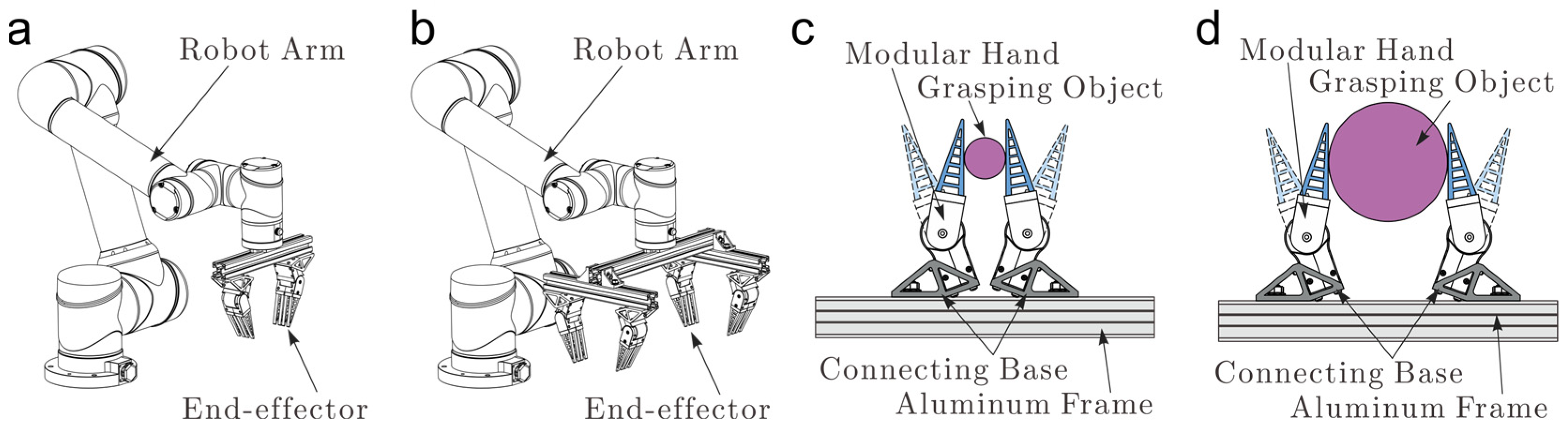
A double-hand robotic end-effector was developed and is depicted in Figure 2a. As shown in Figure 2c,d, the whole end-effector was composed of two modular hands, two connecting bases, a segment of a standard aluminum frame and some standard connecting bolts. The connecting bases are non-standard parts with a very simple structure. In object grasping applications, the position and posture of the modular hand could be easily adjusted by structural parameters and adjustment of the connecting bases. In addition, the installation position of the connecting bases is also flexible in the aluminum frame. As shown in Figure 2c,d, the grasping range of the robotic end-effector could be increased from Figure 2c to d to grasp a larger size object by adjusting the installation position of the two connecting bases. Similarly, the grasping range of the robotic end-effector could also be decreased from Figure 2d to c to grasp an object with smaller dimensions.
Thanks to bus control technology, the number of the modular hand could also be flexible in grasping applications. Under some circumstances, the object may have a heavyweight. In this situation, increasing the number of the modular hand could be feasible. Additionally, a demonstrated quadruple-hand robotic end-effector was developed and is depicted in Figure 2b. Increasing the number of modular hands has two advantages. On the one hand, more modular hands could bear relatively large loads. On the other hand, more hands could apply a more uniform force distribution on the object and guarantee stable object grasping.
It could be concluded that through the modularity design and control bus technology of the robotic hand, both the position, posture, and the number of the modular hand could be flexible in practical applications.
3. Kinematic Modeling of the Modular Hand
The kinematic model of the single hand was established first in this subsection to analyze the kinematic behavior of the multi-hand cooperative operation.
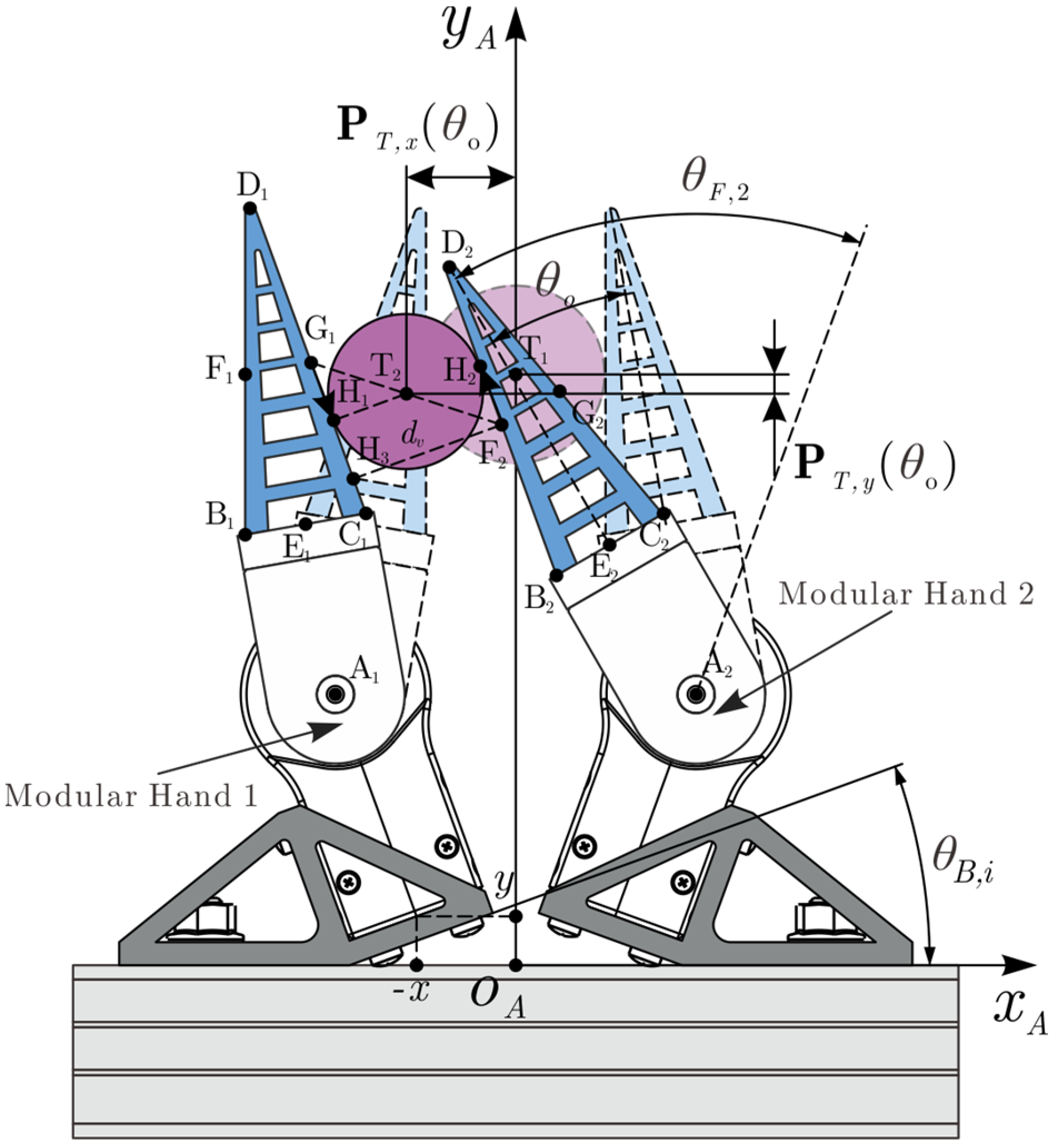
Some featured points, which are points A, B, C, D, E, F and G, were utilized to characterize the finger kinematic behavior, as depicted in Figure 3b. Points F and G are the midpoints of BD and CD, respectively. - is a relative coordinate system attached to a modular hand. was used to describe the rotation of the finger set with respect to the palm. Since the modular hand was 1-DOF, therefore, was the only control parameter. We denoted as the initial posture of the modular hand. According to geometric relation, the displacements of points A-G in the coordinate system - can be obtained directly as:
where the subscript and superscript of P denote the point and coordinate system, respectively.
As illustrated in Section 2, both the position and posture of the modular hand could be adjusted through the structural parameters’ adjustment of the connecting bases to achieve a more flexible application. Therefore, it is more convenient to analyze the kinematic behavior of a modular hand in the absolute coordinate system - as depicted in Figure 3a. The displacement description of points A-G in the coordinate system - could be transferred to the description in a coordinate system - by
where , and are three installation parameters of the connecting base as depicted in Figure 3a,c. In object grasping applications, the position and posture of the modular hand could be flexibly adjusted by configuring the structure parameters, , and . In the following, the displacement of points A-G in the coordinate system - could be expressed as , , , , , and , respectively. Where the i in the subscript denotes the displacement description of the i-th hand.
As depicted in Figure 3a, a and of the i-th hand were adopted to describe the angle of the left and right surface of the soft finger, respectively, since the control target of the modular hand can be different due to the actual grasping state of the hand. As shown in Figure 4, the angle of the right surface of hand 1 () and the angle of the left surface of hand 2 () can be regarded as the control target when the end-effector grasps an object. In multi-hand controlling, the control input can be given as:
where, and are the control target, respectively. Equation (10) is used to control the angle of the left surface of the hand, while Equation (11) is used to control the angle of the right surface of the hand. is an angular offset of the control input; this angle offset is useful in object operations.
As shown in Figure 3, for a given angle offset by the finger rotation, , the two hands can produce posture shifting. At the same time, the position of the object can also be shifted. The position offset of the object could be controlled by . This means using the above multi-hand cooperative operation. The position error of the object could be eliminated by the end-effector itself without the requirement of a manipulator’s pose adjustment. This function is useful in practical grasping applications.
As shown in Figure 4, when the finger angle offset appears and increases gradually, the center of the grasping object moves from to continuously, and the trajectory of the object center, , can be written as:
In application, we are more interested in the relation between finger angle offset and its resultant object lateral displacement . Here, the in the subscript denotes the component. In the simulation, the sequence of could be obtained directly. The simulated lateral displacement could be fitted into an n-order polynomial as:
where denotes the maximum nonlinear fitting error of with respect to . As depicted in Figure 4, when the finger part of the two hands is offset simultaneously, the vertical distance between the two grasping surfaces, that are and , could be obtained by:
As the finger part of the two hands offset, vary continuously. The variation of indicates the grasping strength and, therefore, the stability of the object.
4. Results
4.1. Independent Motion Control of Modular Hand
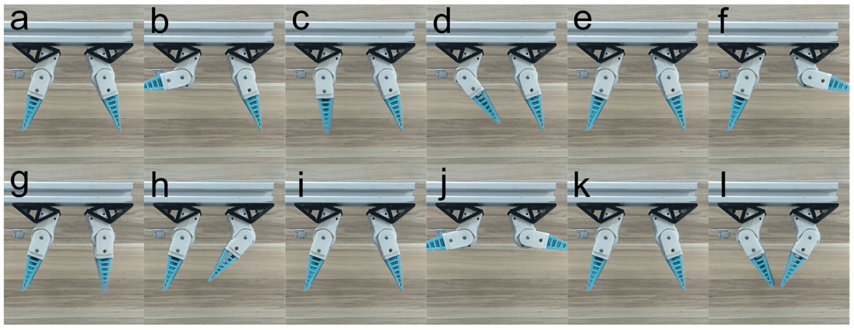
The independent motion control test of the modular hand was conducted based on bus control. In the test, the baud rate of the communication was configured as 115,200 bps to guarantee the motion synchronization of modular hands. In Figure 5, some motion sequences are displayed. In Figure 5a–d, the left hand rotates independently; in Figure 5e–h, the right hand rotates independently; in Figure 5i–l, the two hands rotate simultaneously. It could be verified from Figure 5i to l that the motion of the two hands is almost completely synchronous.
4.2. Object Grasping
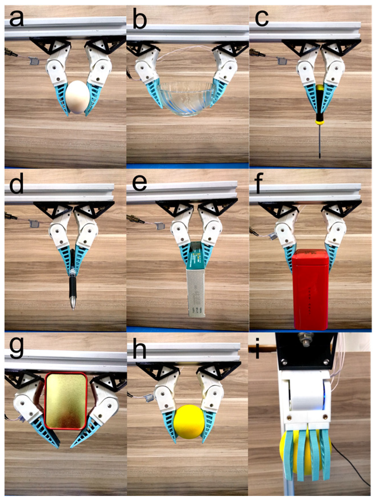
The grasping effectiveness of the double-hand end-effector was evaluated during some object grasping tests. In Figure 6, we report some examples of grasping objects with very different shape features. These include a fragile egg, fragile bowl, slender screwdriver, slender signing pen, deformable drug box and so on. As shown in Figure 6a,b, the grasping range of the end-effector could be easily adjusted by two connecting bases to meet different grasping applications. This verifies the application flexibility and generality of the modular hand.
As depicted in Figure 1d, each finger set of the modular hand consists of four soft fingers. And from Figure 6h,i, it can be observed that the soft fingers deform independently and adapt to the ball surface passively and produce surface contact between the fingers and ball to achieve grasping without any additional control. The independent deformation of the soft fingers could produce a more uniform force distribution on the object surface and guarantee grasping stability.
Due to the position flexibility of the modular hand, the grasping state of the object could be optimized. As shown in Figure 6f, two modular hands can clamp both sides of the box to achieve handling. However, in some cases, the objects may have a relatively larger weight, and the grasping method shown in Figure 6f may not be reliable since the friction produced by the soft finger is limited. Under this circumstance, the position of the modular hand could be adjusted to hold the bottom of the box to achieve handling, as a method shown in Figure 6g. This further demonstrates the adaptability and flexibility of the modular hand in grasping applications.
In object grasping experiments, some key performance of the proposed modular hand was tested. The maximum speed of the grasping motion was about 72.3°/s. The repeatability of the rotation was about 0.1°. The loading capacity was about 3 Kg.
4.3. Object Operation
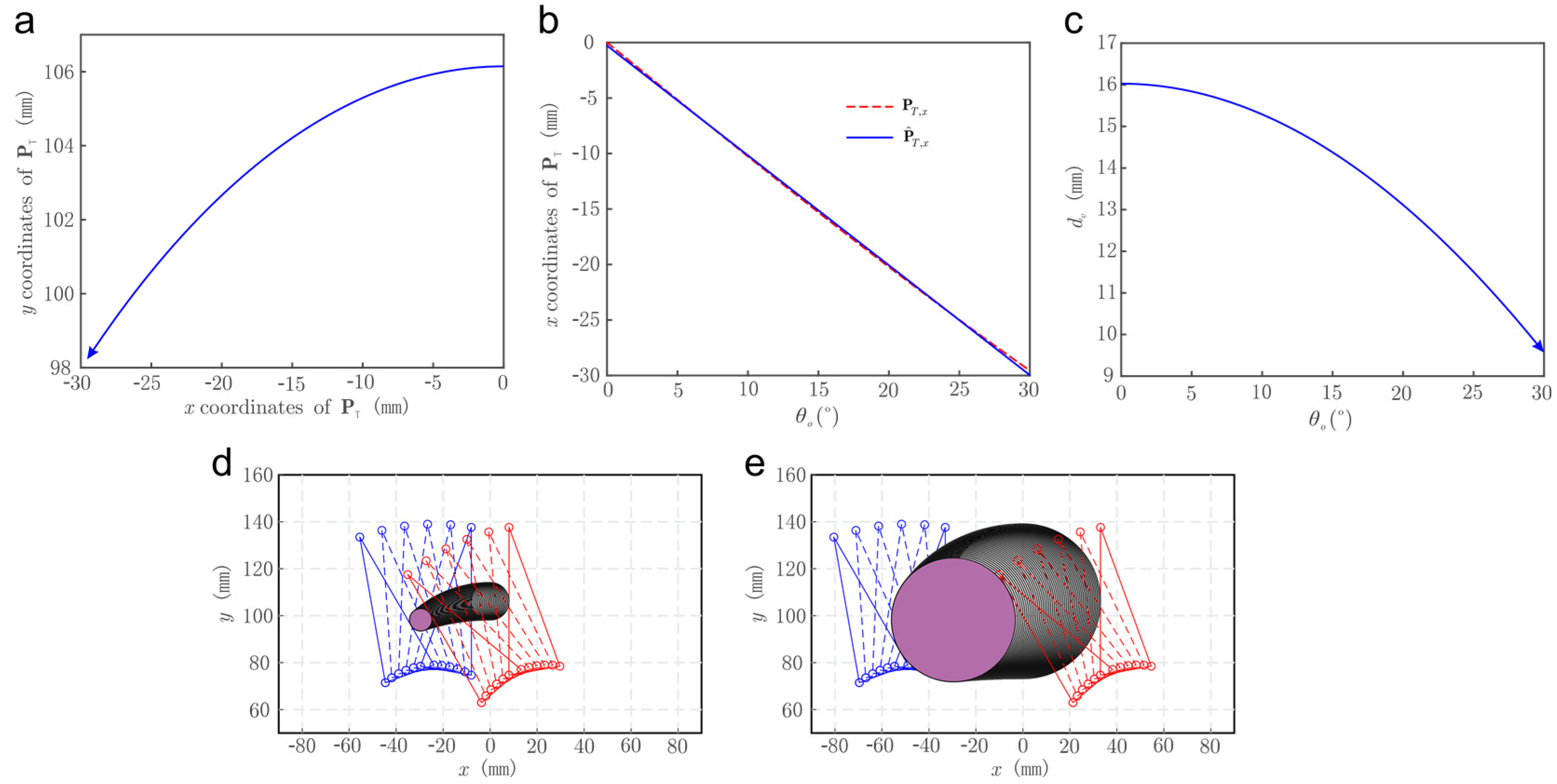
Then a kinematic simulation was conducted to investigate multi-hand cooperative operation behavior. The simulation parameters are as follows, , , , , , , , , and . In the simulation, we increased the angle offset from 0 to 30 gradually.
The trajectory of the object center is simulated and plotted in Figure 7a, where the abscissa and ordinate are and components of respectively. The arrow indicates the trend of movement. Multi-hand cooperative motion sequences are simulated and displayed in Figure 7d,e with different , which were 10 mm and 35 mm, respectively. It can be observed from Figure 7a,d,e that the center of the object produces lateral and vertical displacement simultaneously as increases gradually. To characterize the correlation between and the lateral displacement of the object center, the simulated sequence was fitted into the first-order polynomial as:
using the moving least square method with a maximum nonlinear fitting error of 1.37%. The simulated sequence and fitted are compared in Figure 7b. It can be observed that the two curves coincide well and have an approximate linearity.
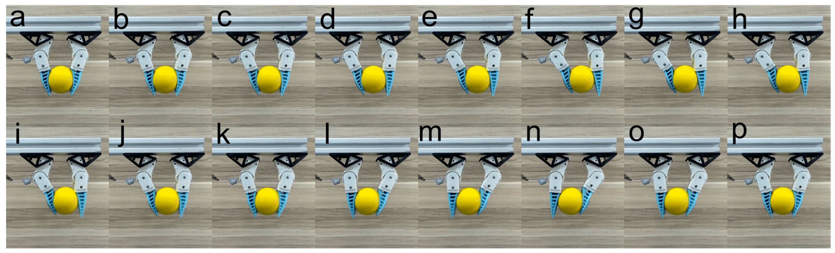
Then the multi-hand cooperative operation function was investigated experimentally by grasping and operating a ball using the double-hand end-effector. In the test, we repeatedly varied the in the range of −30 to 30 linearly. Some movement sequences are presented in Figure 8. It could be observed that the object grasping during the operating process was stable. In fact, the object operation stability was indicated by the vertical distance between the two grasping surfaces . For a certain object grasping, the grasping strength increase as decreases. By contrast, the contact between the grasping surfaces and the object becomes loose as increases. In Figure 7c, a with respect to corresponding to a = 10 mm is plotted. It can be observed that the initial vertical distance between the two grasping surfaces is about 16 mm when = 0. As the finger angle offset increases gradually to 30, decreases to 9.5 mm approximately. This means that during the operation of the object, the two-finger sets clamp the object tighter and guarantee the stability of the object grasping and operation.
5. Conclusions
In the present article, we presented a 1-DOF modular robotic hand inspired by a human two-arm cooperative handling strategy, with the aim of achieving flexible applications in robotic object grasping.
Based on the presented modular hand, two robotic end-effectors (double-hand and quadruple-hand) were developed just using some segments of standard aluminum frames and some connecting bases with a very simple structure to demonstrate the feasibility of the modular hand. The above design permits the fast-grasping range adjustment of the robotic end-effector to meet different grasping requirements.
Some grasping tests were performed with a demonstrated double-hand end-effector to verify the grasping effectiveness of the presented modular hand. In object grasping experiments, some key performances of the proposed modular hand were tested. The maximum speed of the grasping motion was about 72.3. The repeatability of the rotation was about 0.1. The loading capacity was about 3 Kg.
A kinematic model of a modular hand has been developed and validated experimentally, which could provide support for the simulation and the subsequent design of a robotic gripper.
Author Contributions
Conceptualization, Y.L.; methodology, all authors.; software, H.H.; validation, Y.L.; formal analysis, H.H.; investigation, Y.L.; resources, H.H.; data curation, Y.L.; writing—original draft preparation, Y.L.; writing—review and editing, H.H. and M.Z.; visualization, H.H.; supervision, M.Z.; project administration, M.Z.; funding acquisition, M.Z. All authors have read and agreed to the published version of the manuscript.
Funding
This research was funded by the China Postdoctoral Science Foundation, under Grant 2022M721613, the National Natural Science Foundation of China under Grant 62273061, 52105295, 51676099, the Natural Science Foundation of Jiangsu Province under Grant BK20210082, the Natural Science of Foundation of the Jiangsu Higher Education Institutions of China under Grant 21KJB460003 and Changzhou Sci&Tech Program under Grant CM20223013.
Data Availability Statement
Not applicable.
Conflicts of Interest
The authors declare no conflict of interest.
References
- Blanes, C.; Ortiz, C.; Mellado, M.; Beltrán, P. Assessment of eggplant firmness with accelerometers on a pneumatic robot gripper. Comput. Electron. Agric. 2015, 113, 44–50. [Google Scholar] [CrossRef]
- Ji, W.; Qian, Z.; Xu, B.; Chen, G.; Zhao, D. Apple viscoelastic complex model for bruise damage analysis in constant velocity grasping by gripper. Comput. Electron. Agric. 2019, 162, 907–920. [Google Scholar] [CrossRef]
- Zhang, B.; Xie, Y.; Zhou, J.; Wang, K.; Zhang, Z. State-of-the-art robotic grippers, grasping and control strategies, as well as their applications in agricultural robots: A review. Comput. Electron. Agric. 2020, 177, 105694. [Google Scholar] [CrossRef]
- Wang, Z.; Hirai, S. A Soft Gripper with Adjustable Stiffness and Variable Working Length for Handling Food Material. In Proceedings of the 2018 IEEE International Conference on Real-Time Computing and Robotics (RCAR), Kandima, Maldives, 1–5 August 2018; pp. 25–29. [Google Scholar]
- Kuriyama, Y.; Okino, Y.; Wang, Z.; Hirai, S. A Wrapping Gripper for Packaging Chopped and Granular Food Materials. In Proceedings of the 2019 2nd IEEE International Conference on Soft Robotics (RoboSoft), Seoul, Republic of Korea, 14–18 April 2019; pp. 114–119. [Google Scholar]
- Wang, Z.; Torigoe, Y.; Hirai, S. A prestressed soft gripper: Design, modeling, fabrication, and tests for food handling. IEEE Robot. Autom. Lett. 2017, 2, 1909–1916. [Google Scholar] [CrossRef]
- Zhongkui, W.; Keung, O.; Shinichi, H. A dual-mode soft gripper for food packaging. Robot. Auton. Syst. 2020, 125, 103427. [Google Scholar]
- Jiang, S.H.; Song, W.; Zhou, Z.K.; Sun, S.J. Stability analysis of the food delivery robot with suspension damping structure. Heliyon 2022, 8, 18. [Google Scholar] [CrossRef] [PubMed]
- Guo, J.; Low, J.-H.; Liang, X.; Lee, J.S.; Wong, Y.-R.; Yeow, R.C.H. A Hybrid Soft Robotic Surgical Gripper System for Delicate Nerve Manipulation in Digital Nerve Repair Surgery. IEEE ASME Trans. Mechatron. 2019, 24, 1440–1451. [Google Scholar] [CrossRef]
- Selvaggio, M.; Fontanelli, G.A.; Marrazzo, V.R.; Bracale, U.; Irace, A.; Breglio, G.; Villani, L.; Siciliano, B.; Ficuciello, F. The MUSHA underactuated hand for robot-aided minimally invasive surgery. Int. J. Med. Robot. Comput. Assist. Surg. 2019, 15, e1981. [Google Scholar] [CrossRef]
- Sun, Y.; Liu, Y.; Xu, L.; Zou, Y.; Faragasso, A.; Lueth, T.C. Automatic design of compliant surgical forceps with adaptive grasping functions. IEEE Robot. Autom. Lett. 2020, 5, 1095–1102. [Google Scholar] [CrossRef]
- Mouazé, N.; Birglen, L. Bistable compliant underactuated gripper for the gentle grasp of soft objects. Mech. Mach. Theory 2022, 170, 104676. [Google Scholar] [CrossRef]
- Hua, H.; Liao, Z.; Chen, Y.; Xu, C. Design and Test of Compact Series Elastic Force Actuator for Grasping Mechanism. Trans. Chin. Soc. Agric. Mach. 2021, 52, 426–432. [Google Scholar]
- Hua, H.; Song, J.; Liao, Z.; Zhao, J. Design and Experiment of Miniature Linear Series Elastic Actuator for Robotic Grasping. Trans. Chin. Soc. Agric. Mach. 2022, 53, 500–506. [Google Scholar]
- Yoon, S.J.; Choi, M.; Jeong, B.; Park, Y.-L. Elongatable Gripper Fingers With Integrated Stretchable Tactile Sensors for Underactuated Grasping and Dexterous Manipulation. IEEE Trans. Robot. 2022, 38, 2179–2193. [Google Scholar] [CrossRef]
- Yamashita, T.; Suzuki, H.; Tasaki, R. Motion and force measurement of human fingertips during manual operation to achieve high-precision assembly by articulated robots. Meas. Sens. 2022, 20, 100413. [Google Scholar] [CrossRef]
- Ostyn, F.; Vanderborght, B.; Crevecoeur, G. Design and Control of a Quasi-Direct Drive Robotic Gripper for Collision Tolerant Picking At High Speed. IEEE Robot. Autom. Lett. 2022, 7, 7692–7699. [Google Scholar] [CrossRef]
- Hua, H.; Zhao, J.; Liao, Z.; Chen, Y. Unconstrained Bezier Calibration Method for Nonlinear Measurement Calibration Applications: A Comparison Study. IEEE Instrum. Meas. Mag. 2023, 26, 42–50. [Google Scholar] [CrossRef]
- Hua, H.; Song, J.; Zhao, J.; Liao, Z. Sensor-less Grasping Force Control of a Pneumatic Underactuated Robotic Gripper. J. Mech. Robot. 2023, 16, 031005. [Google Scholar] [CrossRef]
- Hua, H.; Liao, Z.; Zhao, J. Design, Analysis, and Experiment of an Underactuated Robotic Gripper Actuated by Linear Series Elastic Actuator. J. Mech. Robot. 2022, 15, 021002. [Google Scholar] [CrossRef]
- Dong, R.W.; Li, M.X.; Sun, A.; Lu, Z.R.; Jiang, D.; Chen, W.Y. Balancing of Motor Armature Based on LSTM-ZPF Signal Processing. Sensors 2022, 22, 9043. [Google Scholar] [CrossRef]
- Gong, Z.; Fang, X.; Chen, X.; Cheng, J.; Xie, Z.; Liu, J.; Chen, B.; Yang, H.; Kong, S.; Hao, Y.; et al. A soft manipulator for efficient delicate grasping in shallow water: Modeling, control, and real-world experiments. Int. J. Robot. Res. 2021, 40, 449–469. [Google Scholar] [CrossRef]
- Jiang, Y.; Chen, D.; Liu, C.; Li, J. Chain-Like Granular Jamming: A Novel Stiffness-Programmable Mechanism for Soft Robotics. Soft Robot. 2019, 6, 118–132. [Google Scholar] [CrossRef] [PubMed]
- Anwar, M.; Khawli, T.A.; Hussain, I.; Gan, D.; Renda, F. Modeling and prototyping of a soft closed-chain modular gripper. Ind. Robot 2019, 46, 135–145. [Google Scholar] [CrossRef]
- Glick, P.; Suresh, S.A.; Ruffatto, D.; Cutkosky, M.; Tolley, M.T.; Parness, A. A Soft Robotic Gripper With Gecko-Inspired Adhesive. IEEE Robot. Autom. Lett. 2018, 3, 903–910. [Google Scholar] [CrossRef]
- Zhu, Y.L.; Gong, W.Z.; Chu, K.M.; Wang, X.; Hu, Z.Q.; Su, H.J. A Novel Wearable Soft Glove for Hand Rehabilitation and Assistive Grasping. Sensors 2022, 22, 6294. [Google Scholar] [CrossRef] [PubMed]
- Pei, G.; Yu, M.; Xu, Y.; Ma, C.; Lai, H.; Chen, F.; Lin, H. An Improved PID Controller for the Compliant Constant-Force Actuator Based on BP Neural Network and Smith Predictor. Appl. Sci. 2021, 11, 2685. [Google Scholar] [CrossRef]
- Li, Y.; Cao, Y.; Jia, F. A Neural Network Based Dynamic Control Method for Soft Pneumatic Actuator with Symmetrical Chambers. Actuators 2021, 10, 112. [Google Scholar] [CrossRef]
- Chavoshian, M.; Taghizadeh, M.; Mazare, M. Hybrid dynamic neural network and PID control of pneumatic artificial muscle using the PSO algorithm. Int. J. Autom. Comput. 2020, 17, 428–438. [Google Scholar] [CrossRef]
- Bourbonnais, F.; Bigras, P.; Bonev, I.A. Minimum-time trajectory planning and control of a pick-and-place five-bar parallel robot. IEEE ASME Trans. Mechatron. 2014, 20, 740–749. [Google Scholar] [CrossRef]
- Wang, D.; Wang, L.; Wu, J. Physics-based mechatronics modeling and application of an industrial-grade parallel tool head. Mech. Syst. Signal Process. 2021, 148, 107158. [Google Scholar] [CrossRef]
- Song, J.; Si, P.; Hua, H.; Qiu, M. Research on the Inherent Nonlinearity Calibration of the Potentiometer of a Miniature Linear Series Elastic Actuator. Actuators 2022, 11, 207. [Google Scholar] [CrossRef]
- Hua, H.; Liao, Z.; Wu, X.; Chen, Y.; Feng, C. A Back-drivable Linear Force Actuator for Adaptive Grasping. J. Mech. Sci. Technol. 2022, 36, 4213–4220. [Google Scholar] [CrossRef]
- Hua, H.; Liao, Z.; Song, J.; Liu, Y. A Sparse Piecewise Calibration Method for Potentiometer with Inherent Nonlinearity: A Comparison Study. Measurement 2022, 204, 112033. [Google Scholar] [CrossRef]
- Hua, H.; Liao, Z.; Wu, X.; Chen, Y. A Bezier based state calibrating method for low-cost potentiometer with inherent nonlinearity. Measurement 2021, 178, 109325. [Google Scholar] [CrossRef]
- Hua, H.; Liao, Z.; Chen, Y. A 1-Dof bidirectional graspable finger mechanism for robotic gripper. J. Mech. Sci. Technol. 2020, 34, 4735–4741. [Google Scholar] [CrossRef]
Figure 1.
Mechanical structures of the modular hand. (a) Major component of the hand, (b) Adaptive object grasping of the soft finger set, (c) Rotation range of the finger set, (d) Assembly schematic of the modular hand, (e) Schematic of the control bus.
Figure 1.
Mechanical structures of the modular hand. (a) Major component of the hand, (b) Adaptive object grasping of the soft finger set, (c) Rotation range of the finger set, (d) Assembly schematic of the modular hand, (e) Schematic of the control bus.

Figure 2.
The application of the modular hand. (a) Double-hand robotic end-effector, (b) Quadruple-hand robotic end-effector, (c,d) The double-hand robotic end-effector with different grasping range by adjusting the installation of the connecting bases.
Figure 2.
The application of the modular hand. (a) Double-hand robotic end-effector, (b) Quadruple-hand robotic end-effector, (c,d) The double-hand robotic end-effector with different grasping range by adjusting the installation of the connecting bases.

Figure 3.
Kinematic model of the modular hand. (a) Absolute coordinate system of the demonstrated double-hand robotic end-effector, (b) Relative coordinate system of the modular hand, (c) Displacement description of the hand in the absolute coordinate system.
Figure 3.
Kinematic model of the modular hand. (a) Absolute coordinate system of the demonstrated double-hand robotic end-effector, (b) Relative coordinate system of the modular hand, (c) Displacement description of the hand in the absolute coordinate system.

Figure 4.
Multi-hand cooperative operation.

Figure 5.
Independent motion control of the modular hand based on the control bus. (a–d) Control of the left hand individually, (e–h) Control of the right hand individually, (i–l) Control of the left and right hands simultaneously.
Figure 5.
Independent motion control of the modular hand based on the control bus. (a–d) Control of the left hand individually, (e–h) Control of the right hand individually, (i–l) Control of the left and right hands simultaneously.

Figure 6.
Grasp objects with different shape features. (a) Fragile egg, (b) Fragile bowl, (c) Screwdriver, (d) Signing pen, (e) Drug box, (f,g) Tea box, (h,i) Ball.
Figure 6.
Grasp objects with different shape features. (a) Fragile egg, (b) Fragile bowl, (c) Screwdriver, (d) Signing pen, (e) Drug box, (f,g) Tea box, (h,i) Ball.

Figure 7.
Multi-hand cooperative handling. (a) Movement trajectory of the object center, (b) Lateral displacement of the object center with respect to , (c) Vertical distance between the two grasping surfaces, (d,e) Finger motion sequences with = 10 mm and 35 mm, respectively.
Figure 7.
Multi-hand cooperative handling. (a) Movement trajectory of the object center, (b) Lateral displacement of the object center with respect to , (c) Vertical distance between the two grasping surfaces, (d,e) Finger motion sequences with = 10 mm and 35 mm, respectively.

Figure 8.
Motion sequences of a double hand operating a ball.

Disclaimer/Publisher’s Note: The statements, opinions and data contained in all publications are solely those of the individual author(s) and contributor(s) and not of MDPI and/or the editor(s). MDPI and/or the editor(s) disclaim responsibility for any injury to people or property resulting from any ideas, methods, instructions or products referred to in the content. |
© 2023 by the authors. Licensee MDPI, Basel, Switzerland. This article is an open access article distributed under the terms and conditions of the Creative Commons Attribution (CC BY) license (https://creativecommons.org/licenses/by/4.0/).
Share and Cite
MDPI and ACS Style
Liu, Y.; Zhao, M.; Hua, H. A 1-DOF Modular Robotic Hand Inspired by Human Two-Arm Cooperative Handling Strategy. Actuators 2023, 12, 151. https://doi.org/10.3390/act12040151
AMA Style
Liu Y, Zhao M, Hua H. A 1-DOF Modular Robotic Hand Inspired by Human Two-Arm Cooperative Handling Strategy. Actuators. 2023; 12(4):151. https://doi.org/10.3390/act12040151
Chicago/Turabian StyleLiu, Yuhang, Maocheng Zhao, and Hongliang Hua. 2023. "A 1-DOF Modular Robotic Hand Inspired by Human Two-Arm Cooperative Handling Strategy" Actuators 12, no. 4: 151. https://doi.org/10.3390/act12040151
Note that from the first issue of 2016, this journal uses article numbers instead of page numbers. See further details here.