

All Acoustical Excitation of Spin Waves in High Overtone Bulk Acoustic Resonator


1
Kotelnikov Institute of Radioengineering and Electronics, Russian Academy of Sciences, Mokhovaya Str. 11, Build 7, 125009 Moscow, Russia
2
Fryazino Branch, Kotelnikov Institute of Radioengineering and Electronics, Russian Academy of Sciences, Vvedenskogo Square, 1, 141190 Fryazino, Russia
*
Author to whom correspondence should be addressed.
Acoustics 2023, 5(1), 268-279; https://doi.org/10.3390/acoustics5010016
Submission received: 13 January 2023
/
Revised: 19 February 2023
/
Accepted: 27 February 2023
/
Published: 1 March 2023
(This article belongs to the Special Issue Resonators in Acoustics)
Abstract
:The hybrid high overtone bulk acoustic wave resonators (HBARs) consisting of a piezoelectric film transducers and gallium gadolinium garnet substrates with yttrium iron garnet films (YIG-GGG-YIG) are used for experimental excitation and detection of acoustically driven spin waves (ADSWs). Two types of HBAR transducers made of Al-ZnO-Al films (differed through the electrodes’ geometry) were deposited onto YIG-GGG-YIG trilayers with different YIG film thicknesses and doping levels and served for excitation of multimode HBAR at gigahertz frequencies. ADSWs were detected by measuring the shifts of resonant HBAR modes in a tangential external magnetic field when the conditions for magnetoelastic resonance (MER) were satisfied. It was shown that the design of the transducer with a continuous bottom electrode provides all acoustical excitation of spin waves (pure ADSWs), suppressing the additional inductive magnetic dynamics excitation due to the electrodes’ geometry. The theoretical study of the HBAR spectrum in a magnetic field showed that the resonance harmonics in the MER region can either almost continuously transfer from one to another, or decay and form an evident magnetoelastic gap. In this case, the shift of resonant frequencies can achieve several intermodal distances. The results obtained are important for applications of HBAR-based devices in spintronics and magnonics.
1. Introduction
Currently, there is a significant surge in interest in the interaction of mechanical vibrations and spin waves and their quanta, phonons and magnons, with each other, as well as with electrons, other quasiparticles and quantum objects (for example, quantum qubits) in various micro and nanostructures [1,2]. Coherent acoustic and spin waves (AW and SW), being slow waves in solids, are of great practical interest and are widely used in the telecommunication and sensor devices of phononics (acoustoelectronics), as well as in the low-energy tunable devices of magnonics and microwave spintronics.
For modern microwave elements, hybrid magnon–phonon systems with the ability to control their characteristics using external magnetic and/or electric fields are of great importance [2,3,4,5,6,7,8]. In addition, in magnon–phonon multiferroic structures containing piezoelectric and ferro(ferri)magnetic (FM) layers, low-energy excitation of “acoustic” SW-ADSW (acoustically driven SW) is achieved due to a combination of magnetoelasticity (ME) [9] and the piezoelectricity existing in different layers of structures, not necessarily in direct contact. The excitation of ADSW occurs due to the alternating electric field in the piezoelectric without the application of alternating magnetic fields and the currents that create them, which can significantly reduce ohmic losses and power consumption [10].
The ME coupling, caused by linear magnetostriction, is strongest near the AW and SW phase synchronism, i.e., at ME resonance (MER) generally excited in the gigahertz frequency range. As a source of SW, surface AWs (SAWs) excited by interdigital transducers are widely used [4,8,11,12,13,14]. However, in the gigahertz frequency range, SAW technology becomes much more complicated due to lithography resolution requirements. Therefore, in this range, bulk acoustic waves (BAWs) compete with SAWs.
One of the ways to excite BAW in the gigahertz frequency range is the use of a high overtone bulk acoustic wave resonator (HBAR) [15,16,17,18]. Currently, the HBAR working frequency up to 40 GHz has been demonstrated [19]. The multi-mode composite HBARs are in high demand as a source of coherent phonons for fundamental and applied research in the fields of quantum acoustodynamics, microwave magnetic straintronics, phononics, photonics, timing applications, etc. [2,20,21,22,23,24].
The most common variation of HBAR is the thickness modes resonator, made by depositing a piezoelectric film transducer on a relatively thick substrate so that the attenuation in the entire structure is determined through the attenuation in the substrate. By choosing a substrate with low AW loss, a high quality factor Q can be obtained. Another feature of this design is a large number of harmonics (which can be more than 1000). The frequency range of effective harmonic generation is determined by the transducer thickness. The advantages of HBARs are their small size, low power consumption and high Q × f product [16].
Our studies of the last decade have been focused on ME interactions in hybrid magnon–phonon HBARs. Similar HBARs in combination with inductive antennas have also been used to amplify or excite ADSW [23,24]. In [25,26,27,28], we experimentally demonstrated and presented a theoretical framework for the effective excitation of both linear and parametric ADSWs in a hypersonic HBAR containing a piezoelectric transducer from a Al-ZnO-Al film deposited onto a structure consisting of a gallium–gadolinium garnet (GGG) single crystal substrate with epitaxial films of yttrium iron garnet (YIG). Additionally, it was shown in [28,29,30] that HBAR containing a thin Pt film in contact with the YIG film is an efficient source of spin current, which is the result of the spin pumping produced by ADSW. Thus, thanks to the extremely low magnetic losses in YIG and the high acoustic quality factor of both GGG and YIG, the YIG-GGG system is very suitable as a basic element in hybrid HBARs for microwave spintronics applications.
A spin current source based on HBAR is a complex system, because several types of excitations simultaneously interact in it, and it is difficult to isolate the contribution of each of them. Understanding the behavior of the HBAR spectrum with an FM layer in a magnetic field makes it possible to extract the contribution of the ME interaction, which is very important for optimizing the device.
This paper presents the results of an experimental study of the spectra of various hybrid HBARs, which were fabricated based on structures containing YIG films with different thicknesses and doping levels, as well as a single-crystal YIG wafer. The results of frequency–field mapping of the microwave reflection coefficient for various structures confirm the regularities of the resonant excitation of linear ADSWs. To excite multimode AW resonances in the gigahertz range, two different types of HBAR transducers made of Al-ZnO-Al films were used. The technology of magnetron sputtering of piezoelectric ZnO films was identical, but the elements’ geometry was different. The design of the transducer with a continuous bottom electrode makes it possible to perform the all-acoustic excitation of SW and to observe their detection as a result of changing the resonant frequencies of the HBAR in a magnetic field.
It was also found that in the MER region, the change in the spectrum for different samples differs significantly and depends on the thickness and location of the FM layers.
2. Materials and Methods
2.1. HBAR Structure and Basic Properties
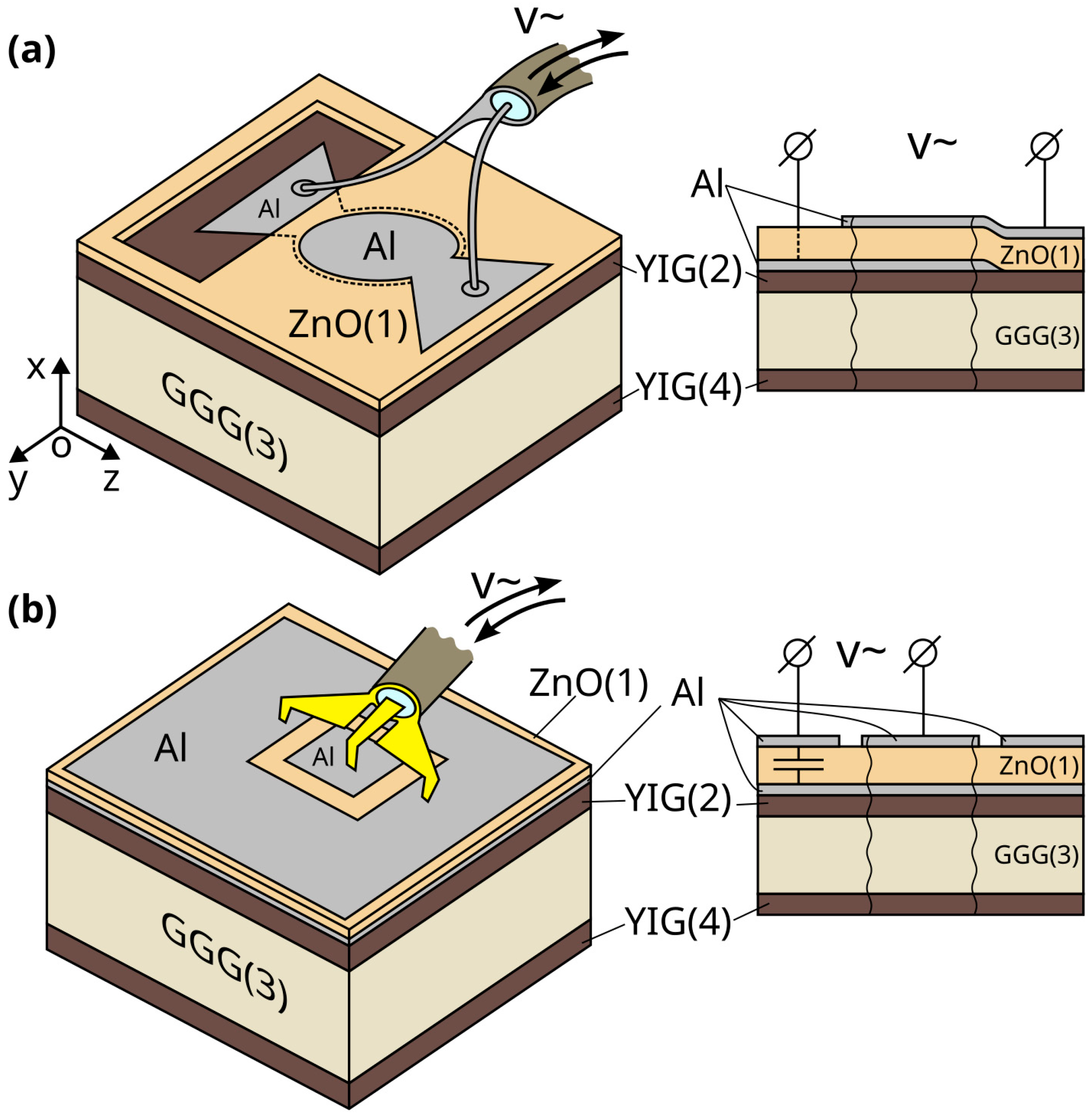
We used two different types of HBARs, shown in Figure 1a,b, respectively. Both types consist of a thin film piezoelectric transducer deposited on the substrate containing the FM layer. The design shown in Figure 1a contains a window in the piezoelectric film for ohmic contact of the RF source with the bottom electrode. This design is better suited for installation in the holder. The design shown in Figure 1b uses the high capacitance between the bottom electrode and the area outside the top electrode to connect the bottom electrode to the RF source. Because the capacitance of the transducer formed between the top electrode and the bottom metal layer is much smaller than the capacitance between the large area outside the top electrode and the bottom metal layer, the response of the entire circuit is dominated by the transducer. The type shown Figure 1b is better suited for precise measurements due to its compatibility with calibrated RF probes.
The fabrication of a piezoelectric transducer was carried out through the successive deposition of Al, ZnO, and Al films. It is shear waves that are fundamental for the interaction of acoustic and magnetic systems, as will be shown below. For effective excitation of shear AW, the ZnO films had a tilted texture axis, which was achieved by shifting the substrate from the center of the zinc target in the process of reactive magnetron sputtering with oxygen [31,32]. After the deposition of each layer, the structural elements were formed via photolithography.
In this work, we experimentally studied three different HBAR devices (hereafter referred to as device 1, device 2 and device 3). ZnO film served as the piezoelectric layer in all devices. Device 1 had a piezo-transducer, as in Figure 1b, and device 2 and device 3 were as in Figure 1a. Devices 1 and 2 were based on commercially available GGG (111) single-crystal substrates with YIG liquid-phase epitaxial layers on both sides. In device 1, pure YIG films (Y3Fe5O12) 15 µm thick were used; in device 2, YIG films substituted with La and Ga with a lower saturation magnetization μ0M0~80–90 mT (compared to 175 mT of pure YIG) and with a thickness of 31 µm were used. Device 3 was based on a YIG (100) single crystal. Device parameters are shown in Table 1.
When the transducer is connected to an external RF circuit, it excites and registers BAWs in the structure due to the direct and inverse piezoelectric effects in the ZnO film. AW propagates along the thickness of the structure and is reflected both from free boundaries and from the interfaces between layers. For both types of piezo-transducers, the vibrational energy is localized under the area of top and bottom electrodes overlapping [33]. In our case, the diameter of the circular electrodes in Figure 1a was 170 μm; the side of the square top electrode in Figure 1b was 200 µm.
Below, we provide a brief description of the theoretical approach to describe the interaction of acoustic and magnetic oscillations in HBAR with a ferromagnet layer.
2.2. Theoretical Description
The foundations of the theoretical description of the ME interaction between AW and SW were laid at the end of the 1950s. In Kittel’s work [9], a formula was obtained for the ME energy density WME of a magnetically ordered cubic crystal and it was shown that the ME interaction leads to a connection between the dynamic equations for the elastic and magnetic subsystems—Newton’s equation for the elastic displacement in a medium with mass density ρ and Landau–Lifshitz equation for precession of magnetization :
Here, γ is the gyromagnetic ratio, μ0 is the magnetic constant, , where = (0, 0, M0) is the saturation magnetization in the constant tangential magnetic field = (0, 0, H0), is the variable magnetization; and are the effective magnetic field and elastic stress tensor, which are found through the variational derivatives of the total energy, taking into account WME. The coordinate system employed corresponds to those in Figure 1a.
In linear 1D approximation, all variables depend on thickness coordinate x and time t as exp[j(k(i)x − ωt)], where , ω = 2πf, k(i) is a wave number for the (i)-th layer. Then, the ME contributions to the effective field and the stress tensor are:
where b ≡ B2 is one of two ME constants for cubic symmetry crystals [9].
It is important to emphasize that, according to (2), only a shear AW with a linear polarization parallel to the magnetic field interacts with magnetization oscillations; therefore, other types of polarizations will not be further taken into account.
For each nonmagnetic layer, Newton’s equation along with Hooke’s law lead to the relationship k(i) = ω/V(i). Here, is a shear AW velocity, ρ(i) is the mass density, and C(i) is the effective elastic modulus for the (i)-th layer. As for magnetic layers the appropriate wave numbers are found form the secular equation, obtained from (1) and (2) together with Maxwell equations, in the following form:
where the upper indices (i) are omitted. Here, the terms in the left hand side represent the dispersion laws for noninteracting AW and SW: and ; ξ is the dimensionless parameter of their interaction, V is the phase velocity of a shear AW, , , Hef (k2)= H0 + Dk2 and Mef ≈ M0 are the uniform effective magnetic field and magnetization, D is the exchange stiffness [9,34]. Equation (3) is biquadratic with respect to ω and is easily solved. The crossover of two independent solutions (3) in the case of ξ = 0 determines MER frequency and wave number:
In the case of ξ ≠ 0, the formation of coupled waves and the repulsion (anticrossing) of the solutions (3) in the vicinity of point (ωMER, kMER) take place. The frequency width of the MER region is determined as a minimal repulsion of coupled ME waves branches ΔωMER = (ξωHωM)1/2. As one can see, for a given real positive ω, the secular Equation (3) becomes bicubic with respect to k2 and has three real roots (p = 1, 2, 3). Using six roots ±k1,2,3, one can construct the general solutions for u = uz, mx,y, and for normal stress component T = Tzx = C(∂u/∂x) + bmx/M0.
The solutions for all layers with thicknesses l(i) should satisfy the elastic and electrodynamic boundary conditions with the additional conditions for mx,y at the magnetic layer boundaries. Here, we used the so-called free spin conditions: ∂mx,y/∂x = 0. The set of equations obtained provides the expression for the complex electric impedance of the piezoelectric transducer:
Here, = [jz−2z(1)tan(θ(1)/2)]/(z(1)tan θ(1)−jz) is the function of phase θ(1), the acoustic impedance of the piezoelectric layer and the acoustic impedance of the adjacent load z(ω, H0), i.e., the GGG substrate and the YIG layers; Kt, and C0 are the effective piezoelectric constant, and the capacity of the piezoelectric layer. The impedance z(ω, H0) contains all the information about ME interactions in FM media and the resonant rearrangement of the HBAR spectrum in a magnetic field. Note that the eigenfrequencies of the structure correspond to the poles of the function F:
z(1)tan θ(1)−jz(ω, H0) = 0.
Using the successive application of the impedance transformation formula for each layer, we obtain an equation for the eigenfrequencies:
θ(3) + arctan(r4,3 tan θ(4)) + arctan[r2,3 tan(θ(2) + δ)] = πn.
Here, δ = arctan(r1,2 tan θ(1)) is the contribution of the piezoelectric layer to the total phase shift; ri,k = z(i)/z(k); θ(3) = k(3)l(3) = ωl(3)/V(3) and z(3)—phase incursion in the substrate and its material acoustic impedance; effective parameters θ(2,4) =K(H0)(2,4)l(2,4), z(H0)(2,4) and K(H0)(2,4)—phase shifts, acoustic impedances and wavenumbers for FM layers. The last values depend on roots k1,2,3 of Equation (3). For more details, see [25,28,30].
To compare the results of the calculation with the experimental results we used below a simple relationship between the microwave reflection coefficient S11 and the electrical impedance Ze = Z0(1 + S11)/(1 − S11) where Z0 is the characteristic impedance (50 Ω) of the RF probes. The losses in the system are taken into account by replacing H0 → H0 + jΔH0, where ΔH0 is FMR line width and C(i) → C(i) + jωη(i), where η(i) is viscosity factor.
2.3. Experimental Methods
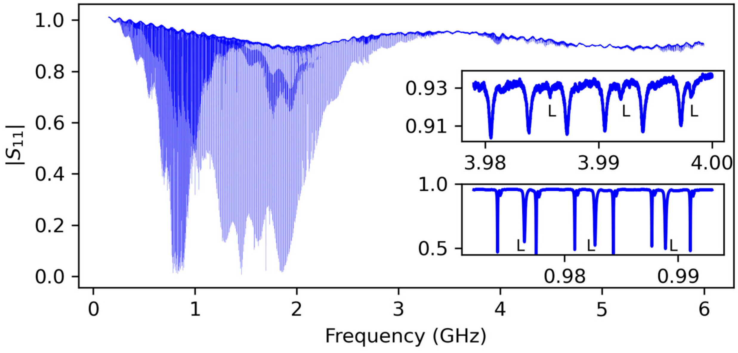
We used a vector network analyzer (VNA) to measure the microwave reflection coefficient S11 in a wide range of frequencies. The frequency dependence of |S11| (spectrum) of the HBAR in the absence of the external magnetic field looks similar to a comb made of evenly distributed resonance dips (harmonics) at frequency fn, where n is the harmonic number. The distance between adjacent harmonics Δ fn = fn − fn−1 in accordance with the ratio (6) slightly oscillates around the mean value with the change of n [32,35,36]. The spectrum of device 1 is shown in Figure 2. The darker areas represent frequency regions of effective shear wave excitation since the shear resonances are more densely placed on the frequency axis than the longitudinal ones. The lower inset corresponds to the frequency at which the magnitudes of the two series of dips (longitudinal and transverse) are close. The top inset represents the frequency at which longitudinal resonances are suppressed, which is convenient for analyzing the results.
To measure 2D maps of |S11(f, H0)| we placed the studied HBAR in the electromagnet controlled by the computer. The external magnetic field H0 was oriented in the plane of the structure and magnetized YIG films up to uniform saturation magnetization M0. The VNA was also controlled by that computer. Before the start of the experiment, a set of frequencies {F} and a set of magnetic fields {H} were selected. At each step of the procedure, the next value of H0 from {H} was set on the electromagnet, and the |S11(f, H0)| spectrum was recorded for each f from {F}.
3. Results
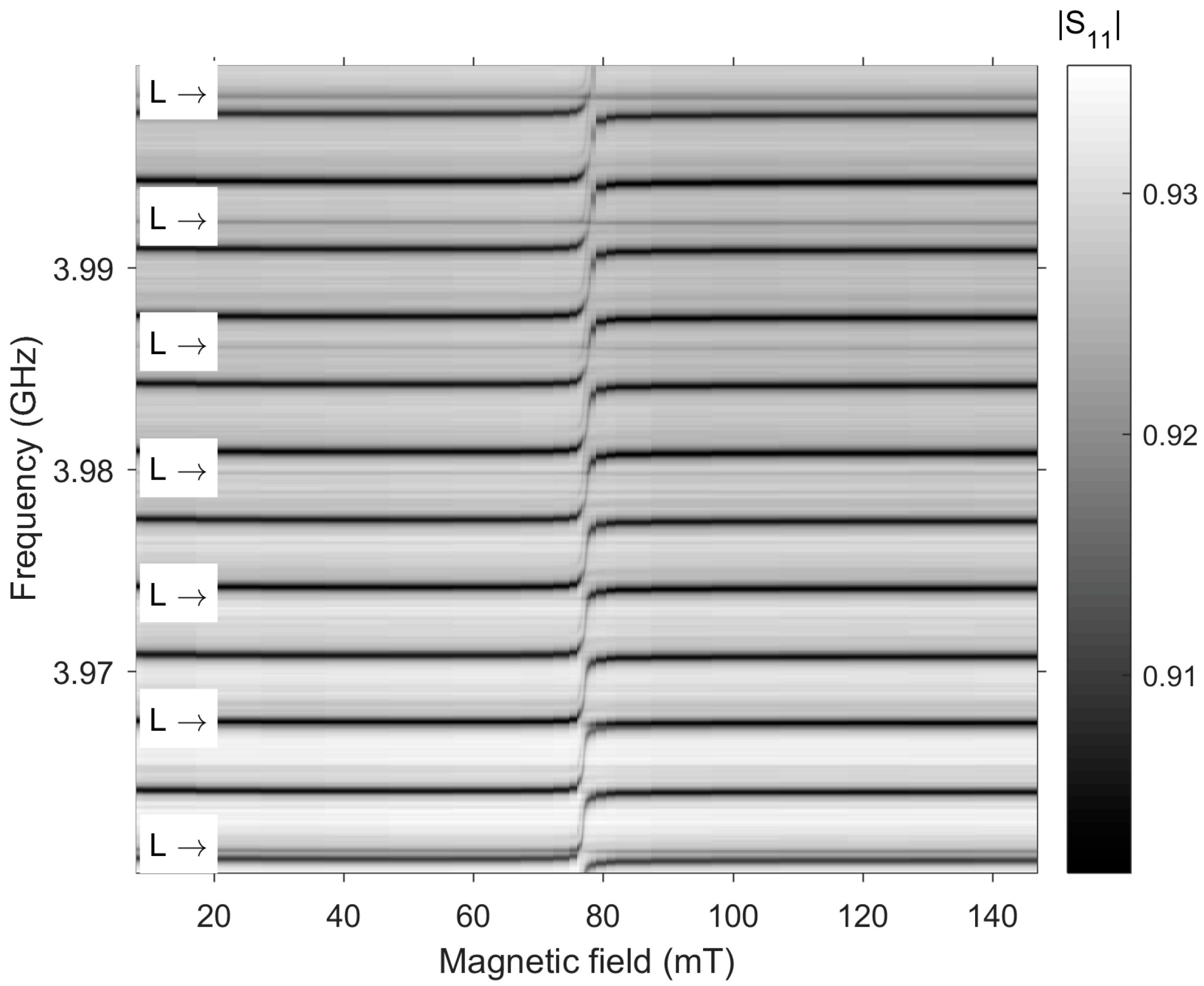
The dependence of the HBAR resonant frequencies on the magnetic field for device 1 is shown in Figure 3. The excitation efficiency of longitudinal waves in this range is low; therefore, for clarity, the corresponding resonances are marked with the symbol “L”. It can be seen that the magnetic field does not affect them. Shear waves resonances are more recognizable. One can see the mode tuning in the field range 75–80 mT (associated with MER) in the entire intermodal frequency range. In this case, an “apparent” merging of the frequencies of two adjacent overtones n and n + 1 occurs at the center of the intermodal distance.
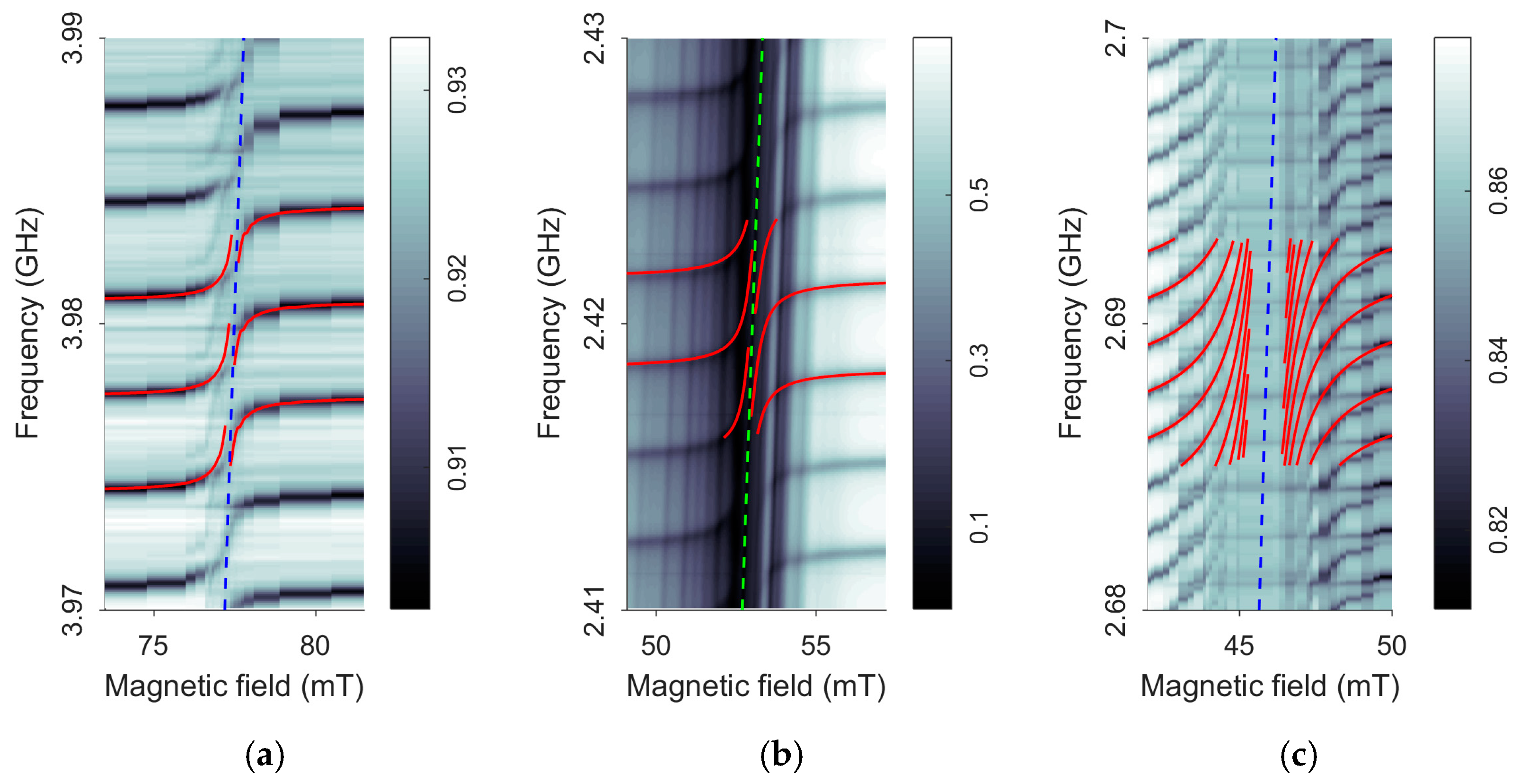
However, a more detailed study of the behavior of the spectrum in a magnetic field shows that the pattern of frequency tuning in the MER region is more complex. Figure 4a shows the MER region, as well as the result of numerical fitting using the theoretical model for device 1, as well as two other devices.
Figure 4 clearly shows the characteristic rearrangement of resonant frequencies in the MER region localized along the fMER(H0) lines. The position of the fMER(H0) line corresponds to the conditions for the intersection of the dispersion branches of noninteracting AW and SW (see (4), Section 2.2). The detuning of resonant frequencies of HBAR is a consequence of the inverse effect of resonant excitation of spin-wave dynamics, ADSW, in magnetic films [23,26,28]. Figure 4b shows that for device 2, in addition to the excitation of resonant ADSWs, there is also the excitation of magnetic oscillations propagating in the plane, such as surface and bulk magnetostatic waves (MSWs). These excitations form a distinct quasi-vertical relief of dark and light bands. The fact that the nature of these features is associated with the MSW spectrum is confirmed by the correspondence of these bands slopes to the slope of the Kittel line fMER(H0) = (γμ0/2π)[H0(H0 + M0)]1/2. The reason for the MSW excitation in device 2 is the specific elongated shape of the transducer electrodes (Figure 1a), which creates an alternating magnetic field around them. In a structure with a continuous bottom electrode on the YIG surface (Figure 1b), it is possible to suppress such inductive excitation of the MSW.
Figure 4c shows the three-dimensional dependences |S11(f, H0)| for device 3, which consists of a substrate in the form of a YIG (100) single crystal plate, on which a transducer of the first type is deposited (see Figure 1b). Since the substrate of device 3 was about two times thicker than that of devices 1 and 2, the intermodal distance Δfn is to be half that of other devices.
Numerical solutions for the shift of resonant frequencies obtained on the basis of the theoretical model above (see also [25,28,30]) are shown in Figure 4 with the red lines. The values of the adjustable parameters, namely the effective magnetization M0 and the magnetoelasticity constant, are given in Table 1.
For all the devices, there is a detuning of resonant frequencies and the manifestation of an ME gap, whose width δHG depends on the filling factor of the FM medium Φ = (l(2) + l(4))/Dtot (Dtot is the total thickness of the structure) and is maximal for a monolithic FM resonator (c). In this case, the frequency tuning exceeds several intermodal distances. In Figure 4a,b, the ME gap decreases significantly and the spectral branches on both sides of the MER gap approach the MER line but do not pass into each other.
The types of HBAR considered here do not exhaust all possible variants of HBAR with an FM layer. A variant of the YIG-GGG structure with a single FM film is of particular interest; therefore, we modeled it theoretically and compared the result with the experimental data of the device with two films (device 1).
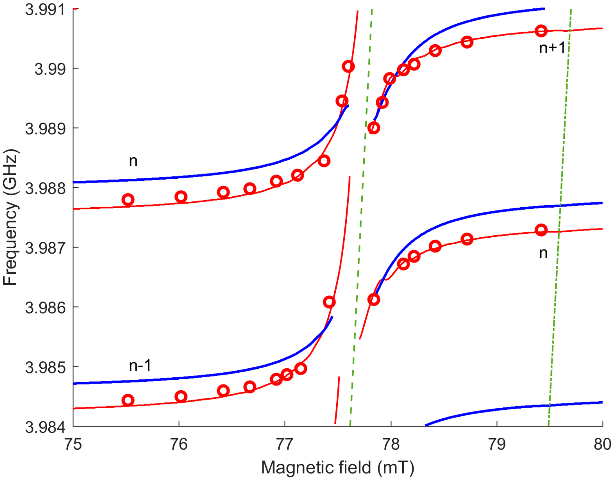
Figure 5 shows the behavior of the resonant frequencies of the HBAR as a function of the magnetic field for device 1. Red circles show the same experimental data as in Figure 4a. The solid red curves were calculated according to the parameters from Table 1. The circles show a gap δHG between resonant branches with numbers n and n + 1 located on opposite sides of the MER line, where all modes completely disappear. As the resonances approach the MER line, they lose their quality factor and their position is less well-defined. Therefore, the ascending and descending branches, n and n + 1, seem to transit into each other (see Figure 4), although this does not in fact happen. The theoretical red lines show that resonances can move even closer to the MER line and the minimum distance (δHG)theory < δHG will then take place for branches with numbers n − 1 and n + 1.
The blue curves show the simulation results for the structure with the same Dtot and Φ, but with only one double thickness YIG layer on the opposite side from the transducer. The behavior of the resonant branches outside the MEP region is of the same character; however, the advance into the MEP region becomes slower: the frequency shift does not even reach half the intermodal distance. This can be explained by the fact that the behavior of the resonant frequencies depends not only on the change in the phase shift over the total thickness of the FM medium, caused by the rearrangement of the dispersion dependences, but also on the change in the boundary conditions due to the ME contribution to the elastic stress tensor (see Section 2.2). This contribution enters (6) through the functions ri,k, namely through the impedances z(H0)(2,4). Note also that even far from the MER, the resonant frequencies of the two structures in Figure 5 are slightly shifted because 2 arctan x ≠ arctan 2x. This difference becomes significant in the MER region.
4. Discussion
Let us consider some resonant modes’ parameters and their behavior in the magnetic field. If we neglect the mismatch of the acoustic impedances of the layers, i.e., ri,k =z(i)/z(k) = 1 in (6), then we obtain a simplified equation θ(3) + θ(4) + θ(2) + θ(1) = πn to find resonant frequencies. In this case, the HBAR spectrum is characterized by a comb of equidistant resonant frequencies fn separated by Δfn = Vtot/(2Dtot), ≈3 MHz, where Vtot is the effective velocity of AW front propagation in the structure. For comparison, the ME splitting of dispersion branches in FM media (see, Section 2.2) is ΔfMER = ΔωMER/2π, ≈30 MHz. Thus, more than 10 HBAR resonant frequencies appear directly in the MER region, which is seen in Figure 3. In this case, the region of magnetic fields near HMER, in which resonant frequencies are rearranged, is found to be μ0ΔHMER = 2πΔfMER/γ, ≈6 mT.
Neglecting the exchange stiffness, it can be shown that the approximate expressions for the ME wave phase velocity in YIG may be written as V(H) = V(2,4)(0)[1 + 0.5ξωMωH/(ω2 − ω02)]. The change of the velocities in the YIG layers will lead to the change in Vtot. Therefore, the resonance condition requires the shift of the resonant frequency δfn(H) = fn(H) − fn(0) ≈ fn(0)ΦξRe[fMfH/(fn(0)2 − fFMR2)]. This expression qualitatively explains the slower change of fn(H) in film structures, for which the filling factor Φ ≪ 1 (device 1 and device 2) compared to the monolithic one with Φ ≈ 1 (device 3). The latter also applies to a decrease in Q-factor of the resonances. For the same value of the magnetic damping parameter ΔH0, a decrease in the Q-factor of the HBAR resonances and further to complete disappearance of the regular resonance structure occurs in the field gap δHG = δHG(ΔH0, Φ, ξ) proportional to Φ. Summing up, we present the following relations for frequency and field intervals:
fn ≫ ΔfMER ≫ Δfn, δfn (H0),
HFMR ≫ HMER ≫ ΔHMER > δHG > ΔH0.
Consider now the role of exchange. The calculated dependencies f(H0)FMR and f(H0)MER, represented by dash-dotted and dotted lines are shown in Figure 5. At a given frequency, the fields of the corresponding resonances are related as HMER = HFMR − Hex, where μ0Hex = μ0Dk2 ≈ 1.8 mT is the field of inhomogeneous exchange, k = kMER = 2πfn/V(2,4) ≈ 6 × 10⁶ rad/m. Thus, we can conclude that as the external field decreases in the range HFMR > H0 > HMER, the ADSW wave numbers change in the range from zero to kMER and exceed kMER in the field region HMER > H0 > HMER + ΔHMER/2.
Note that for the thick YIG films used in the work, the individual spin wave resonances (SWRs) merge at H0 near HFMR and it makes sense to speak of a continuous SW spectrum. In contrast, at lower fields, in particular, at H0 ≈ HMER, an AW resonance with number n interacts with a separate high-order SWR with number s = kMERl(2,4)/π ≈ 30. The developed theoretical approach correctly takes into account all solutions of (3) and boundary conditions (of unpinned spins) and is applicable to ME interactions of AW modes with both FMR (s = 0) and SWR (s = 1, 2, 3…). For micron YIG films and thinner, the excitation of individual SWRs is accompanied by a slight shift of only one resonator mode, as was theoretically shown in [25]. To detect such acoustically driven SWR, it is efficient to use acoustic spin pumping into a heavy metal film in contact with YIG(4) [37].
5. Conclusions
Experimental studies of acoustic excitation of magnetic dynamics (ADSW) in hybrid HBARs of various configurations containing piezoelectric and FM layers (ZnO and YIG) have been carried out. ADSW was detected by measuring the shift of resonant frequencies in a magnetic field. This shift is a consequence of the back action of ADSW on the elastic subsystem of all layers and is most significant when the condition of magnetoelastic resonance is satisfied. At AW frequencies fn(H) higher than the MER line, the quasi-magnetic modes with wavenumbers more than 6 × 10⁶ rad/m are excited, whereas at fn(H) lower than the MER line frequency, the wavenumbers of excited modes are essentially smaller. The resonant excitation of ADSW can be accompanied by an additional inductive excitation of the magnetic dynamics due to the transducer electrodes. It is shown that the design of the transducer with a continuous bottom electrode makes it possible to acoustically excite SWs.
A detailed study of the resonant frequencies behavior in the MER region showed that the branches of the spectrum located on opposite sides of the MER line form a gap relative to the magnetic field. The gap value depends on the filling factor of the FM medium. In the case of YIG films, the gap is rather small and the branches almost continuously move from one to another with a shift by an integer number of harmonics. In the case of bulky YIG, the branches form a more evident magnetoelastic gap where all modes completely disappear; however, along the gap edges, the shift of resonant frequencies can significantly exceed the intermodal distance.
Author Contributions
Conceptualization, S.A. and N.P.; methodology, V.L.; formal analysis, N.P.; investigation, S.A.; writing—original draft preparation, S.A.; writing—review and editing, N.P. All authors have read and agreed to the published version of the manuscript.
Funding
This work was supported by the Ministry of Science and Higher Education of the Russian Federation as part of the state assignment.
Institutional Review Board Statement
Not applicable.
Informed Consent Statement
Not applicable.
Data Availability Statement
The data presented in this study are available on request from the corresponding author.
Conflicts of Interest
The authors declare no conflict of interest.
References
- Awschalom, D.D.; Du, C.R.; He, R.; Heremans, F.J.; Hoffmann, A.; Hou, J.; Kurebayashi, H.; Li, Y.; Liu, L.; Novosad, V.; et al. Quantum Engineering with Hybrid Magnonic Systems and Materials (Invited Paper). IEEE Trans. Quantum Eng. 2021, 2, 1–36. [Google Scholar] [CrossRef]
- Delsing, P.; Cleland, A.N.; Schuetz, M.J.A.; Knörzer, J.; Giedke, G.; Cirac, J.I.; Srinivasan, K.; Wu, M.; Balram, K.C.; Bäuerle, C.; et al. The 2019 Surface Acoustic Waves Roadmap. J. Phys. D Appl. Phys. 2019, 52, 353001. [Google Scholar] [CrossRef]
- Barman, A.; Gubbiotti, G.; Ladak, S.; Adeyeye, A.O.; Krawczyk, M.; Gräfe, J.; Adelmann, C.; Cotofana, S.; Naeemi, A.; Vasyuchka, V.I.; et al. The 2021 Magnonics Roadmap. J. Phys. Condens. Matter 2021, 33, 413001. [Google Scholar] [CrossRef] [PubMed]
- Puebla, J.; Hwang, Y.; Maekawa, S.; Otani, Y. Perspectives on Spintronics with Surface Acoustic Waves. Appl. Phys. Lett. 2022, 120, 220502. [Google Scholar] [CrossRef]
- Latcham, O.S.; Gusieva, Y.I.; Shytov, A.V.; Gorobets, O.Y.; Kruglyak, V.V. Controlling Acoustic Waves Using Magneto-Elastic Fano Resonances. Appl. Phys. Lett. 2019, 115, 082403. [Google Scholar] [CrossRef]
- An, K.; Litvinenko, A.N.; Kohno, R.; Fuad, A.A.; Naletov, V.V.; Vila, L.; Ebels, U.; de Loubens, G.; Hurdequint, H.; Beaulieu, N.; et al. Coherent Long-Range Transfer of Angular Momentum between Magnon Kittel Modes by Phonons. Phys. Rev. B 2020, 101, 060407. [Google Scholar] [CrossRef] [Green Version]
- Litvinenko, A.; Khymyn, R.; Tyberkevych, V.; Tikhonov, V.; Slavin, A.; Nikitov, S. Tunable Magnetoacoustic Oscillator with Low Phase Noise. Phys. Rev. Appl. 2021, 15, 034057. [Google Scholar] [CrossRef]
- Yang, W.-G.; Schmidt, H. Acoustic Control of Magnetism toward Energy-Efficient Applications. Appl. Phys. Rev. 2021, 8, 021304. [Google Scholar] [CrossRef]
- Kittel, C. Interaction of Spin Waves and Ultrasonic Waves in Ferromagnetic Crystals. Phys. Rev. 1958, 110, 836–841. [Google Scholar] [CrossRef]
- Cherepov, S.; Khalili Amiri, P.; Alzate, J.G.; Wong, K.; Lewis, M.; Upadhyaya, P.; Nath, J.; Bao, M.; Bur, A.; Wu, T.; et al. Electric-Field-Induced Spin Wave Generation Using Multiferroic Magnetoelectric Cells. Appl. Phys. Lett. 2014, 104, 082403. [Google Scholar] [CrossRef] [Green Version]
- Geilen, M.; Nicoloiu, A.; Narducci, D.; Mohseni, M.; Bechberger, M.; Ender, M.; Ciubotaru, F.; Hillebrands, B.; Müller, A.; Adelmann, C.; et al. Fully Resonant Magneto-Elastic Spin-Wave Excitation by Surface Acoustic Waves under Conservation of Energy and Linear Momentum. Appl. Phys. Lett. 2022, 120, 242404. [Google Scholar] [CrossRef]
- Küß, M.; Heigl, M.; Flacke, L.; Hefele, A.; Hörner, A.; Weiler, M.; Albrecht, M.; Wixforth, A. Symmetry of the Magnetoelastic Interaction of Rayleigh and Shear Horizontal Magnetoacoustic Waves in Nickel Thin Films on LiTaO3. Phys. Rev. Appl. 2021, 15, 034046. [Google Scholar] [CrossRef]
- Uchida, K.; An, T.; Kajiwara, Y.; Toda, M.; Saitoh, E. Surface-Acoustic-Wave-Driven Spin Pumping in Y3Fe5O12/Pt Hybrid Structure. Appl. Phys. Lett. 2011, 99, 212501. [Google Scholar] [CrossRef]
- Weiler, M.; Huebl, H.; Goerg, F.S.; Czeschka, F.D.; Gross, R.; Goennenwein, S.T.B. Spin Pumping with Coherent Elastic Waves. Phys. Rev. Lett. 2012, 108, 176601. [Google Scholar] [CrossRef] [PubMed] [Green Version]
- Driscoll, M.M.; Jelen, R.A.; Matthews, N. Extremely Low Phase Noise UHF Oscillators Utilizing High-Overtone, Bulk-Acoustic Resonators. IEEE Trans. Ultrason. Ferroelectr. Freq. Control 1992, 39, 774–779. [Google Scholar] [CrossRef] [PubMed]
- Lakin, K.M. Thin Film Resonator Technology. IEEE Trans. Ultrason. Ferroelectr. Freq. Control 2005, 52, 707–716. [Google Scholar] [CrossRef]
- Mansfeld, G.D.; Alekseev, S.G.; Polzikova, N.I. Unique Properties of HBAR Characteristics. In Proceedings of the 2008 IEEE Ultrasonics Symposium, Beijing, China, 2–5 November 2008; pp. 439–442. [Google Scholar]
- Sorokin, B.P.; Kvashnin, G.M.; Volkov, A.P.; Bormashov, V.S.; Aksenenkov, V.V.; Kuznetsov, M.S.; Gordeev, G.I.; Telichko, A.V. AlN/Single Crystalline Diamond Piezoelectric Structure as a High Overtone Bulk Acoustic Resonator. Appl. Phys. Lett. 2013, 102, 113507. [Google Scholar] [CrossRef]
- Sorokin, B.P.; Asafiev, N.O.; Kvashnin, G.M.; Scherbakov, D.A.; Terentiev, S.A.; Blank, V.D. Toward 40 GHz Excitation of Diamond-Based HBAR. Appl. Phys. Lett. 2021, 118, 083501. [Google Scholar] [CrossRef]
- Gokhale, V.J.; Downey, B.P.; Katzer, D.S.; Nepal, N.; Lang, A.C.; Stroud, R.M.; Meyer, D.J. Epitaxial Bulk Acoustic Wave Resonators as Highly Coherent Multi-Phonon Sources for Quantum Acoustodynamics. Nat. Commun. 2020, 11, 2314. [Google Scholar] [CrossRef]
- Daugey, T.; Friedt, J.-M.; Martin, G.; Boudot, R. A High-Overtone Bulk Acoustic Wave Resonator-Oscillator-Based 4.596 GHz Frequency Source: Application to a Coherent Population Trapping Cs Vapor Cell Atomic Clock. Rev. Sci. Instrum. 2015, 86, 114703. [Google Scholar] [CrossRef]
- Tian, H.; Liu, J.; Dong, B.; Skehan, J.C.; Zervas, M.; Kippenberg, T.J.; Bhave, S.A. Hybrid Integrated Photonics Using Bulk Acoustic Resonators. Nat. Commun. 2020, 11, 3073. [Google Scholar] [CrossRef] [PubMed]
- Chowdhury, P.; Jander, A.; Dhagat., P. Nondegenerate Parametric Pumping of Spin Waves by Acoustic Waves. IEEE Magn. Lett. 2017, 8, 3108204. [Google Scholar] [CrossRef]
- Fung, T.C.; Karenowska, A.D.; Gregg, J.F. Broadband phonon to magnon conversion in yttrium iron garnet. Mater. Quantum Technol. 2021, 1, 011003. [Google Scholar] [CrossRef]
- Polzikova, N.; Alekseev, S.; Kotelyanskii, I.; Raevskiy, A.; Fetisov, Y. Magnetic Field Tunable Acoustic Resonator with Ferromagnetic-Ferroelectric Layered Structure. J. Appl. Phys. 2013, 113, 17C704. [Google Scholar] [CrossRef]
- Polzikova, N.I.; Alekseev, S.G.; Raevskii, A.O. Parametric Pumping of Magnons in a Hybrid Magnon–Phonon Resonator. J. Commun. Technol. Electron. 2021, 66, 1296–1301. [Google Scholar] [CrossRef]
- Alekseev, S.G.; Dizhur, S.E.; Polzikova, N.I.; Luzanov, V.A.; Raevskiy, A.O.; Orlov, A.P.; Kotov, V.A.; Nikitov, S.A. Magnons Parametric Pumping in Bulk Acoustic Waves Resonator. Appl. Phys. Lett. 2020, 117, 072408. [Google Scholar] [CrossRef]
- Polzikova, N.I.; Alekseev, S.G.; Luzanov, V.A.; Raevskiy, A.O. Electroacoustic Excitation of Spin Waves and Their Detection Due to the Inverse Spin Hall Effect. Phys. Solid State 2018, 60, 2211–2217. [Google Scholar] [CrossRef]
- Polzikova, N.I.; Alekseev, S.G.; Pyataikin, I.I.; Luzanov, V.A.; Raevskiy, A.O.; Kotov, V.A. Frequency and Magnetic Field Mapping of Magnetoelastic Spin Pumping in High Overtone Bulk Acoustic Wave Resonator. AIP Adv. 2018, 8, 056128. [Google Scholar] [CrossRef] [Green Version]
- Polzikova, N.I.; Alekseev, S.G.; Luzanov, V.A.; Raevskiy, A.O. Acoustic Excitation and Electrical Detection of Spin Waves and Spin Currents in Hypersonic Bulk Waves Resonator with YIG/Pt System. J. Magn. Magn. Mater. 2019, 479, 38–42. [Google Scholar] [CrossRef] [Green Version]
- Luzanov, V.A.; Alekseev, S.G.; Polzikova, N.I. Deposition Process Optimization of Zinc Oxide Films with Inclined Texture Axis. J. Commun. Technol. Electron. 2018, 63, 1076–1079. [Google Scholar] [CrossRef]
- Alekseev, S.G.; Luzanov, V.A.; Polzikova, N.I. Study of Spatial Distribution of Piezoelectric Properties of ZnO Films by Acoustic Resonator Spectroscopy. J. Commun. Technol. Electron. 2020, 65, 1339–1344. [Google Scholar] [CrossRef]
- Alekseev, S.G.; Mansfeld, G.D.; Polzikova, N.I. Trapping of Acoustic Energy in Composite Resonators Based on Cubic Crystals. J. Commun. Technol. Electron. 2006, 51, 925–931. [Google Scholar] [CrossRef]
- Strauss, W. Magnetoelastic properties of yttrium iron garnet. In Physical Acoustics; Mason, W.P., Ed.; Academic Press: New York, NY, USA, 1968; Volume IV(B), pp. 211–268. [Google Scholar]
- Zhang, Y.; Wang, Z.; Cheeke, J.D.N. Resonant Spectrum Method to Characterize Piezoelectric Films in Composite Resonators. IEEE Trans. Ultrason. Ferroelectr. Freq. Control 2003, 50, 321–333. [Google Scholar] [CrossRef] [PubMed]
- Alekseev, S.G.; Kotelyanskii, I.M.; Polzikova, N.I.; Mansfel’d, G.D. Study of Layered Structures Using Modified Acoustic Resonator Spectroscopy. J. Commun. Technol. Electron. 2015, 60, 300–307. [Google Scholar] [CrossRef]
- Alekseev, S.G.; Polzikova, N.I.; Raevskiy, A.O. Yttrium Iron Garnet Thickness Influence on the Spin Pumping in the Bulk Acoustic Wave Resonator. J. Commun. Technol. Electron. 2019, 64, 1318–1322. [Google Scholar] [CrossRef] [Green Version]
Figure 1.
Schemes of the HBAR consisting of YIG(2)-GGG(3)-YIG(4) and piezoelectric transducers based on ZnO films (1) with different shapes of Al electrodes and different types of contact with the bottom electrode (a) with ohmic contact (b) with capacitive contact.
Figure 1.
Schemes of the HBAR consisting of YIG(2)-GGG(3)-YIG(4) and piezoelectric transducers based on ZnO films (1) with different shapes of Al electrodes and different types of contact with the bottom electrode (a) with ohmic contact (b) with capacitive contact.

Figure 2.
Frequency dependence (spectrum) of the microwave reflection coefficient |S11(f)| in the absence of a magnetic field. The insets show two enlarged fragments of the spectrum. The dips in the frequency characteristics correspond to the resonant frequencies of the shear AW (not marked) and longitudinal AW (L) thickness modes; the intermodal distance of the longitudinal modes is approximately two times greater than that of the shear ones.

Figure 3.
Frequency and magnetic field dependencies of |S11(f, H)| for device 1. The arrows show the positions of the resonant frequencies of the longitudinal (L) AW, three of which correspond to the frequencies in the inset in Figure 2.
Figure 3.
Frequency and magnetic field dependencies of |S11(f, H)| for device 1. The arrows show the positions of the resonant frequencies of the longitudinal (L) AW, three of which correspond to the frequencies in the inset in Figure 2.

Figure 4.
Frequency and magnetic field dependencies of |S11(f, H0)| for the devices under study: (a) for device 1; (b) for device 2; (c) for device 3. The red lines are the results of the theoretical calculation with the fitting parameters of Table 1. The dashed lines are the positions of the lines fMER(H0).

Figure 5.
Magnetic field dependencies of resonance frequencies for device 1. The circles indicate the positions of the resonances in the experimental data from Figure 4a; red lines—approximation of these data by a model with two 15 µm YIG layers; blue lines—the result of the calculation of the model with only one YIG layer of 30 μm; the green dotted line is the MER line; the green dash-dotted line is the FMR line. The calculations were performed for D = 4.5 × 10⁻¹⁴ mT·m2.


Table 1.
Properties of the devices and model fitting parameters.
| No. | Transducers, Figure 1 | YIG | Thickness, of YIG, μm | Thickness, of GGG, μm | μ0M0, mT | b, MJ/m3 |
|---|---|---|---|---|---|---|
| 1 | (b) | 2 films, pure | 15 | 500 | 175 | 0.38 |
| 2 | (a) | 2 films, doped | 31 | 500 | 86 | 0.31 |
| 3 | (a) | 1 plate, pure | 1180 | 0 | 151 | 0.48 |
Disclaimer/Publisher’s Note: The statements, opinions and data contained in all publications are solely those of the individual author(s) and contributor(s) and not of MDPI and/or the editor(s). MDPI and/or the editor(s) disclaim responsibility for any injury to people or property resulting from any ideas, methods, instructions or products referred to in the content. |
© 2023 by the authors. Licensee MDPI, Basel, Switzerland. This article is an open access article distributed under the terms and conditions of the Creative Commons Attribution (CC BY) license (https://creativecommons.org/licenses/by/4.0/).
Share and Cite
MDPI and ACS Style
Alekseev, S.; Polzikova, N.; Luzanov, V. All Acoustical Excitation of Spin Waves in High Overtone Bulk Acoustic Resonator. Acoustics 2023, 5, 268-279. https://doi.org/10.3390/acoustics5010016
AMA Style
Alekseev S, Polzikova N, Luzanov V. All Acoustical Excitation of Spin Waves in High Overtone Bulk Acoustic Resonator. Acoustics. 2023; 5(1):268-279. https://doi.org/10.3390/acoustics5010016
Chicago/Turabian StyleAlekseev, Sergey, Natalia Polzikova, and Valery Luzanov. 2023. "All Acoustical Excitation of Spin Waves in High Overtone Bulk Acoustic Resonator" Acoustics 5, no. 1: 268-279. https://doi.org/10.3390/acoustics5010016