
Digital Twin-Enabled Decision Support in Mission Engineering and Route Planning


Systems Engineering Department, Naval Postgraduate School, Monterey, CA 93943, USA
*
Author to whom correspondence should be addressed.
Systems 2021, 9(4), 82; https://doi.org/10.3390/systems9040082
Submission received: 5 August 2021
/
Revised: 5 November 2021
/
Accepted: 11 November 2021
/
Published: 14 November 2021
(This article belongs to the Section Systems Engineering)
Abstract
:This article presents a Model-Based Systems Engineering (MBSE) methodology for the development of a Digital Twin (DT) for an Unmanned Aerial System (UAS) with the ability to demonstrate route selection capability with a Mission Engineering (ME) focus. It reviews the concept of ME and integrates ME with a MBSE framework for the development of the DT. The methodology is demonstrated through a case study where the UAS is deployed for a Last Mile Delivery (LMD) mission in a military context where adversaries are present, and a route optimization module recommends an optimal route to the user based on a variety of inputs including potential damage or destruction of the UAS by adversary action. The optimization module is based on Multiple Attribute Utility Theory (MAUT) which analyzes predefined criteria which the user assessed would enable the successful conduct of the UAS mission. The article demonstrates that the methodology can execute a ME analysis for route selection to support a user’s decision-making process. The discussion section highlights the key MBSE artifacts and also highlights the benefits of the methodology which standardizes the decision-making process thereby reducing the negative impact of human factors which may deviate from the predefined criteria.
1. Introduction
The 4th Industrial Revolution (I4.0), also referred to as “Industry 4.0”, has changed the way many industries work across the world in recent years. As described by Klaus Schwab, founder of the World Economic Forum, I4.0 will be driven largely by the convergence of digital, biological, and physical innovation [1]. One could understand I4.0 as the blurring of boundaries between the digital, biological, and physical worlds. This is made possible with rapidly increasing computing power and data transfer rates. It brings about great potential to increase productivity, while communication will be easier and transportation will be faster [2] thereby enabling the proliferation of technology in the fields of Internet-of-Things (IOT), Artificial Intelligence (AI) and machine learning, 3D printing and genetic engineering, to name a few [3].
Just as in other industries, I4.0 has made its impact on the military. There are three drivers for military change: (1) pressure from senior leadership, (2) emulation of other professional militaries, and (3) an external shock [4]. We argue that I4.0 is fueling all three military change drivers with the pace and extent of I4.0 proliferating across different technologies used by the military. For instance, the Department of Defense (DoD) was reported to have increased its unclassified investments in AI from USD 600 million FY2016 to USD billion in FY2021 [5]. In the same light, China was reportedly planning to spend USD billion by 2020 to develop a core AI industry [5]. Military operations enabled by I4.0 technologies may transpire so fast that it requires humans to be out of the decision-cycle [6]. In this regard, we expect I4.0 to also drive rapid development and adoption of Digital Twin (DT) and Mission Engineering (ME) in a Model-Based Systems Engineering (MBSE) paradigm.
The United States (US) DoD has a track record of embracing new technologies and incorporating them into DoD operational capabilities. In recent years, there has been much more emphasis and communication on the digital transformation strategy. In June 2018, the DoD released the Digital Engineering Strategy which laid out five goals including: (1) formalize the development, integration, and use of models to inform enterprise and program decision making; (2) provide an enduring, authoritative source of truth; (3) incorporate technological innovation to improve engineering practice; (4) establish a supporting infrastructure and environment to perform activities, and collaborate and communicate across stakeholders; (5) transform the culture and workforce to adopt and support digital engineering across a system’s lifecycle [7]. Of note to this article is the first goal where the Digital Engineering Strategy mentions formally developing and integrating models to support engineering activities and decision making across the system lifecycle. With more intelligent weapon systems such as autonomous robotics and unmanned vehicles (including the entire System of Systems (SOS) of the remotely-operated vehicle, the control station, etc.) being fielded, there is increased emphasis on the need for accurate models and decision support algorithms that would enable users to better make use of these systems.
In this article, we argue that in a combat situation, with several operations happening at any given time in a dynamic environment, the use of DT environment may enhance the decision-making process for the mission planner. We suggest that the DT environment, armed with the requisite data inputs, is able to support the mission planner and provide valuable insights into the benefits and trade-offs for each route that are being assessed.
Specific Contribution
In this article, we propose a methodology that aids mission planners in the development of a DT model that is able to provide quantitative decision support analysis for Unmanned Aerial System (UAS) route selection. The method is based on Multiple Attribute
Utility Theory (MAUT) [8], and uses portions of the MagicGrid framework [9] and Bickford et al.’s framework, hereafter referred to as the Operationalized Digital Twin Framework (ODTF) [10], each of which offers different methodologies for decomposing stakeholder needs into system specifications through MBSE processes. We provide insights on the steps and inputs required for the development of the DT model to support a deployed DT that supports operations analysis and routing decisions for a system.
2. Background and Literature Review
This section discusses concepts and recent related work that are relevant to the methodology we propose in this article.
2.1. Digital Twin
In 2012, the National Aeronautics and Space Administration (NASA) defined DT as an “integrated multiphysics, multiscale, probabilistic simulation of an as-built vehicle or system that uses the best available physical models, sensor updates, fleet history, etc.” [11]. In other words, a DT is a virtual representation of a physical asset, based on onboard data generated within the asset and delivered to the DT, which assists stakeholders with maintenance, planning, and operational decisions among other activities. More recent definitions for Digital Twin from the American Institute of Aeronautics and Astronautics (AIAA) and Digital Twin Consortium define a DT as “a virtual representation of a connected physical asset” [12] and “a virtual representation of real-world entities and processes, synchronized at a specified frequency and fidelity” [13].
The term DT, considered by some as a subset of a digital representation, has different meanings to different communities with a wide range of use cases and levels of fidelity. Due to the lack of a standard definition, the ODTF generalized the definition of a digital twin to “a model that helps stakeholders answer specific questions by providing a readily available rapidly testable digital analog to the system of interest” [10]. It is important to note that when fielding DTs, only a subset of the total parametric data generated throughout design, manufacture, operations, and maintenance is used and an extensive digital shadow persists. It should be noted that DTs can be co-developed with a system throughout the system lifecycle including prior to the system being deployed. Further, DTs can be developed for physical and software systems [10]. In this way, as system and DT complexity grow, the DT can become a system in itself, and the DT-physical asset relationship a DT can be considered a SOS.
DT can be characterized by the following features: (1) having a linked collection of relevant digital artifacts including engineering data, operation data and behavior descriptions via several simulation models [14]. The simulation models making up the DT are specific for their intended use and apply suitable fidelity for the problem to be solved. (2) The DT evolves along with the real system throughout the whole life cycle and integrates currently available knowledge about the system. (3) The DT is not only used to describe behavior but also to derive solutions relevant to the real system.
In many cases, the DT is connected to the real system (either a physical system, a cyber-physical system, or a software system) during development, manufacturing, deployment, operation, etc. In other words, a DT is connected to the real system throughout the entire system lifecycle. Generally this includes some form of data synchronization between the real system and the DT although the data synchronization may not be real-time depending on a variety of factors such as bandwidth constraints between a forward-deployed real system and its DT or a DT operating in an austere environment. In such cases, there may be several DTs with varying levels of fidelity and synchronicity between the real system and a maintenance facility or server farm [10].
Being in a virtual environment, a DT allows users the capability to test the system beyond its physical limits which is something that often cannot be done easily and/or inexpensively with the physical system. This enables the user to better understand how the system behaves in different circumstances, and allows for further optimization of the system components [15]. Due to these advantages, DT can be applied to a multitude of applications. Examples include (1) a Prognostic and Health Management (PHM) methodology that predicts reliability failure probabilities for a nuclear power plant [16], (2) a system performance validation where a model is used to compare the performance of different de-icing systems on an aircraft [17], (3) a list of applications for DT including those above as well as: (3.1) provide decision support to users through what-if analysis, and (3.2) discover new application opportunities and revenue streams through modifying and testing new system features and improvements [18].
The benefits of DT go beyond conducting test and analysis; DT is valuable in enhancing decision support as argued by Madni [18]. This is especially true in complex systems and challenging operating environments where multiple decisions have to be made by a human, often within a compressed timeframe with limited or incomplete information. As discussed by Kunath and Winkler, the quality of each decision depends on the experience of the decision-maker and the available information [19]. In addition, if a decision is made based on manual calculations, the accuracy can be very low [19]. DT is well placed to overcome these issues. Marakas identifies three fundamental components of a decision support system as: (1) a knowledge base, (2) a decision context (model), and (3) an interface. DT meets all three criteria [20]. This is further evident in the many research and industry applications where DT has been used. Some examples include enhancing decision support for port operations [21] and improving the management of logistic systems [22].
DT stakeholders can include almost anyone involved in a system life cycle such as sponsoring organizations, systems engineers and architects, subject matter experts, acquisitions organizations, operators and system users, maintainers, logisticians, the communities impacted by systems, national governments and elected leaders, the public, and even adversaries. Because DTs can have so many uses, DT stakeholders can be an extremely wide and diverse group, and similar to MBSE models, each stakeholder has a different use case or interest in the DT. Thus while generalizations can be made about different groups of potential DT stakeholders, individual DT development processes will have unique stakeholders.
2.2. Mission Engineering
ME is defined as the deliberate planning, analyzing, organizing, and integrating of current and emerging operational and system capabilities to achieve desired mission effects (warfighting, space mission scientific return, etc.) [23,24]. According to the DoD ME guide, ME entails the employment of systems and SOS in an operational context to provide information on system performance which can support decisions made by the users in pursuit of achieving mission success. Notably, the guide [23] describes ME as a data-driven approach to analyze key aspects of a mission to derive quantifiable trade-offs and make decisions. This enables one to test new concepts or tactics that have not been proven. Suffice to say, the concept of ME relies on I4.0 technology and the ability to exploit DT modeling and simulations.
An earlier perspective on ME depicts a notional framework for ME [25]. The various functions of ME (defining mission requirements, identifying mission concept of operation, mission design, and mission architecture) are used to optimize the mission solution. The mission solution serves to meet predefined stakeholder needs. While this definition is broad, it is aligned to the definition that the DoD later standardized upon.
The amount of factors that could impact a mission outcome is practically infinite, thus conducting an empirical study is an essential part of ME [23]. Hence, it is important to note that the utility of the analysis is a function of the data accuracy input to the model. Additionally, the practitioner must have a good understanding of the mission objective to be able to define useful Measures of Effectiveness (MOE) and Measure of Performance (MOP) which quantify and measure the success of the system. These elements are critical for quantitative and subsequent qualitative assessment of the system being modeled.
2.3. Mission Planning
We use mission planning as an umbrella term to encapsulate several closely related concepts such as mission routing, mission route planning [26], etc. In general, mission planning sets objectives, allocates resources, develops perspective routes, and contingencies. In this subsection we briefly review several of the closely related concepts that are encapsulated within mission planning.
Mission routing is often considered to be a combinatorial optimization research topic that has been extensively studied due to its application to many transportation challenges [27]. This is coupled with the rise in applications of autonomous vehicles such as UAS in defense, aerospace, and other civilian industries. The deployment and recovery of one autonomous marine vehicle [28] is nontrivial, and for a multi-vehicle fleet, the challenge is compounded [29]. Each vehicle requires a specialized team to plan, launch and recover it [28]. The same can be said for UAS.
Routing and planning decisions are important especially in contexts where systems may be exposed to non-nominal conditions such as in a military context, a space exploration context, etc. because the decisions analyze several priority variables such as the potential for inclement weather and proximity of hazards that can impact the success of the mission [30,31,32,33]. Notably, the cost of time for employing resources against the risk of exposure to threats is a key criterion to consider. In this regard, using a constant route time as an assumption can lead to poor route planning and inefficient use of resources [34]. A mission planner must consider several factors to ensure that the UAS has the best chance of completing the mission [35]. In a military operating environment, every sortie allocated to the operator contributes to the overall chance of mission success. In a resource-tight environment, the ability to deploy assets optimally increases operational effectiveness contributing to the chance of mission success [36]. Beyond the cost of each flight, in a military context, the survivability of an asset is often determined by the ability to avoid threats. Aircraft survivability modus operandi were developed during the emergence of military helicopter operations in the 1950s; the procedures were based on two principles: (1) avoid detection, and (2) if detected, avoid being hit [37]. Hence, the mission planner ideally chooses a route that has the lowest threat probability. Considering all of the above, one can appreciate the importance of mission planning.
2.4. Model-Based Systems Engineering and Digital Twin
International Council on Systems Engineering (INCOSE) defines MBSE as “the formalized application of modelling to support system requirements, design, analysis, verification and validation activities beginning in the conceptual design phase and continuing throughout development and later life cycle phases” [38]. Technological advancements in computational capabilities on top of greater emphasis on key principles of Systems Engineering (SE) have markedly increased the use of MBSE although the traditional SE approach remains dominant in many industries [39]. The ODTF discusses that MBSE and the vision of DT are closely aligned, and if system models can be integrated into the operations and sustainment phase of a system’s lifecycle, the integrated models can become a DT [10]. As such, a MBSE methodology can be employed to develop a system’s DT.
The decision process of architecting the DT can be mapped onto the MBSE and SE processes [10]. In doing so, the system requirements can also be mapped across to drive the development of the DT achieving synergy as much of this data is normally specified in the system development process. Table 1 provides a view of the mapping of DT architecture with the MBSE processes via the ODTF and a mapping to the MagicGrid process (discussed below). The ODTF categorizes critical phases of the DT architecting process into: (1) concept exploration, (2) preliminary design, (3) detailed design, (4) implementation, (5) test and evaluation, and (6) operations and maintenance. The ODTF further goes on to present a case study of an unmanned surface vessel to describe the process of building a DT for the purpose of predicting failures, tracking reliability, aiding in maintenance planning, and indicating the probability of a future failed mission. Note that while the ODTF examines failure rates of major subsystems and components and how that may impact the probability of future mission success or failure, the work presented in this article focuses on route selection to balance the chance of mission failure against other mission parameters. While we have observed in our professional practices many implementations of DT only occurring after a system has been constructed and fielded, the ODTF and many other DT-related articles suggest DT development happen in parallel with system development [10,40]. The critical phases of system architecting that ODTF outlines mirrors the phases of a notional system design process.
2.5. MagicGrid
There are many programming languages that are being used commercially such as JavaScript, Matlab, etc. While these languages are versatile and capable of performing a wide range of automation and visualization tasks, they lack several features that directly support characterizing systems and supporting trade studies. Thus, a new dialect of Unified Modeling Language (UML) (a modeling language) was developed into Systems Modeling Language (SysML) by INCOSE and Object Management Group (OMG) [41]. SysML provides graphical representation of the data in a repository [42]. It supports modeling, analysis, and verification of complex systems. It is considered by many as the de facto modeling language for SE [41]. The MagicGrid framework is based on SysML and is explained by the four pillars of SE: Requirement, Behavior, Structure, and Parametrics. The pillars are broken down into nine corresponding diagram notations using SysML.
The Requirement pillar depicts stakeholder needs. Goals and objectives of the system are defined under the system requirements. Component requirements are the subsystem requirements needed for the system to perform its functions. The Behavior pillar covers the use cases for the system. Use cases describe the user needs or the actor in SysML. The inputs and peer systems required for the system to operate are expressed in the use case diagrams. Functional analysis describes the behavior of the system by decomposing every function performed by the subsystem. Component behavior demonstrates the detailed behavior of the subsystems. The Structure pillar includes the high-level interfaces required for the system to connect with its peer systems. The logical subsystems communication covers interactions between the various subsystems. The component structure depicts the physical interfaces between the component and its sub-components. Finally, the Parametric Pillar covers the MOE and physical characteristics of the system.
We assess that there are several similarities between the ODTF and the MagicGrid framework (and other frameworks, standards, and handbooks [43,44,45,46]). Table 1 provides a comparison of the ODTF against the MagicGrid Process. In other words, what the ODTF describes using the SE process of Concept exploration stage to Detailed Design stage covers a large part of the MagicGrid framework of modeling a system using SysML with some disparities. Notably, we assess that MagicGrid specifically defines the system MOE as a key component of the MagicGrid framework. In the ODTF article, it is highlighted that DT developers should work with component subject matter experts to identify how subcomponent performance is traceable to system-level performance in order to derive suitable system performance indicators [10]. Having said that, the ODTF process is more practical than the MagicGrid process in that they take into consideration the requirements for data storage as well as the integration into a physical design. This is an important consideration as the data are both a key resource and output for a DT.
Thus, we argue that in a dynamic combat situation, using a DT may enhance the decision-making process for the mission planner. We suggest that the DT environment, armed with the requisite data inputs, is able to support the mission planner and provide valuable insights into the benefits and trade-offs for each route that are being assessed. Section 3 proposes a methodology to accomplish this goal.
2.6. UAS for Last Mile Delivery
Last Mile Delivery (LMD) in a military context is the distribution of supplies from the last point of bulk disaggregation to dispersed forces in the theater of operations [47]. The nature of warfare today is increasingly complex and dispersed, hence autonomous vehicles used for resupply are expected to make multiple stops on distribution missions to scattered forces [47]. In a contested environment, the delivery system is also exposed to the threat of being disrupted by adversaries which is in addition to system and environmental limitations such as weather conditions, battery or fuel limitations, etc. All these factors must be considered by the operator especially for a UAS platform where humans are not constantly providing tactical judgment to system operations. Furthermore, the magnitude of the challenge is exacerbated if one is considering the use of multi-UAS or swarming operations, which has been an area of research by United Kingdom (UK)’s Defence Science and Technology Laboratory (DSTL) and Defense Advanced Research Projects Agency (DARPA) [28], among others. Hence, a decision support module of the system in a DT environment is valuable to the operator in managing multiple systems and multiple routes in a dynamic environment similar to that of military operations. The case study (Section 4) examines a LMD to demonstrate the proposed methodology.
2.7. Developing a System Model through Multi-Attribute Utility Theory
In the case study, we use MAUT. This subsection provides information and equations necessary to implement the case study.
MAUT is an established method for decision-makers to compare performance metrics and to determine trade-offs between them [48]. As discussed by Dyer [49], MAUT provides an axiomatic foundation for decisions that involves several criteria. The axioms impart rationale for quantitative analysis of alternatives. In the LMD case study, the operator or an AI software is expected to determine the most optimal route for the UAS based on a set of criteria determined by the mission lead. These criteria serve to allow the UAS a higher probability of success to complete the mission and return to base. The additive value model is widely used by practitioners when conducting multi-objective decision analysis [50]. The following objective function is used to evaluate each alternative routes:
where is the alternative’s value function. to n is the number of criteria (attribute). is the alternative’s score on the ith criteria. is the single dimensional value of a score of . is the weight for each of the ith criteria and .
The additive value model evaluates the trade-offs for the objectives by calculating the alternative’s contribution to the value measures. Each value function measures returns to scale based on the range of the value of measure and calculates a score to a value. A value scale with the minimum acceptable value of measure: lower threshold, and the most desired value of the value of measure: upper threshold, should also be determined [51]. Initial development of the threshold values generally occurs during the requirements phase of a mission engineering process. Stakeholders that include military planners, operators, and others will have knowledge of specific requirements, doctrine, and issuances from their organizations which may factor into developing threshold values. Further, prior experience and stakeholder preference factor into developing the thresholds values. The process of developing the threshold values will be different for every unique group of stakeholders and there is no one-size-fits-all approach that we can recommend.
The weights play an important role in the objective value of the function. As the summation for all the criteria comes up to 1, this forces the operator to prioritize between the criteria. For example, if the Time to Target is the most important aspect of the UAS LMD mission, it should be given the highest weightage.
To obtain , a scaled scoring for the particular criteria should be calculated, we do this by using the following equation:
Having a scaled value of 1 means that the alternative achieves the goal value while a scaled value of 0 means that the alternative achieved the threshold value. The objective function is calculated and compared for each route to determine the preferred solution based on the weights or priorities set by the operator.
We note the additive value model may have its inherent weakness as it does not take into account the variation of the scales of the criteria [50]. Not using swing weights may result in the recommended alternative not being consistent with the stakeholders’ preference [51]. While swing weights are important for the quality of the decision, our focus is on demonstrating the methodology of creating a DT after stakeholder requirements have been captured so specific details into swing weights will not be covered in detail as it is assumed they have already been completed.
2.8. Route Selection Criteria
For the purpose of the case study, three criteria are evaluated to select the route with the highest objective function. They are: (1) time to target, (2) remaining battery power, and (3) threat probability. The subsequent subsections discuss each in turn.
2.8.1. Time to Target
For the purpose of LMD, it is reasonable to assume that the time to target is a key criterion to determine the most optimal route. As highlighted by Thornton and Gallasch, potential use cases of LMD may include delivery of emergency resupply of ammunition or medical supplies [47]. As such, the utility curve for this criterion to the operator is determined to be a decreasing Returns To Scale (RTS) concave; in other words, less is better. The operator prefers to reach the target in the shortest possible time. Beyond a certain time period, the case study assumes there is a steep drop in utility as the unit waiting for resupply could have already been overrun by an adversary. The time to target is assumed to be the straight-line distance divided by the speed of the UAS. The typical speed of UAS based on current technology and is assumed to be 20 m per second [52].
2.8.2. Probability of Hit
In a hostile environment, it is likely that there are adversarial threats along the routes to the target. The threats can impact the probability of success for the case study’s LMD mission. In accordance with the Army Military Decision Making Process (MDMP), the operator should select the course of action that minimizes risk to the force and to mission accomplishment [53]. While the UAS is able to autonomously calculate potential routes, for threat data the UAS requires access to external resources with real-time updated threat information. The data of interest is the probability of hit, . The probability of hit is the probability that every process of the engagement sequence is successfully completed [54]. As the probabilities are not correlated, i.e., each step has to complete before the next can begin, the probability of hit may be expressed as:
The refers to the probability that the threat is active. refers to the probability that the weapon has been commanded to engage the UAS. Finally, refers to the probability that the weapon is launched and detonates at the UAS. The utility curve for this criterion to the operator is determined to be a decreasing RTS concave, in other words, less is better. The operator prefers to keep the probability as low as possible with a steep decrease in utility beyond a certain point.
2.8.3. Remaining Battery life
System recoverability is a key aspect of system survivability [55]. The operator wants to ensure that the UAS has sufficient battery life to return to base regardless of the route selected. As such, the utility curve of this criteria is determined to be linear RTS, in other words, more is better.
The main demand of the battery comes from the UAS’s propulsion system. The percentage of battery energy remaining, can be determined by the following equations [56]:
where —energy demand is attributed to mechanical power to the propellers , power loss , multiplied by time of in operation. is obtained by multiplying the voltage and capacity of the model of battery in use [56].
3. Method for the Development of a DT for Route Selection Decision Support
The following section describes the methodology for the development of the system DT and the operations analysis. Figure 1 shows the proposed six steps of the methodology for the creation of DT for route selection decision support.
3.1. Step 1: Define Stakeholder Needs
The stakeholders’ needs for DT should be clearly defined in two aspects. First, defining the physical design. That is, the capabilities and functions of the system of interest should be clearly defined. An accurate depiction of the sub-system interaction and use-cases enhances the accuracy of the model and the results obtained from subsequent operations analysis. Second, the goals of the operations analysis or the variable of interest should also be stated upfront. This ensures that all sub-systems related to the particular variable are captured upfront in the design of the DT. A similar approach is mentioned by Beery and Paulo [57], where the need for two parallel processes of creating the operational design and the physical design of the system is essential for a MBSE analysis process.
3.2. Step 2: Create a Digital Twin of the System
Having defined the requirements, the DT equivalent of the system can now be developed. This can be done in various MBSE software such as CORE or CAMEO Enterprise Architecture. We recommend employing a software tool that is capable of using SysML. SysML’s inclusion of Requirement and Parametric diagrams makes it more suitable for modeling system requirement and performance than many alternatives [58]. One may also use the Object Process Methodology (OPM) to represent the system architecture if one’s organization is more accustomed to OPM. Both modeling languages are equally capable with subtle differences such as the OPM having only a single integrated model with objects, processes, and relationships instead of different views as in SysML [58]. As we used the CAMEO Enterprise Architecture software in the case study, we chose to use the MagicGrid framework previously discussed in Section 2.5.
3.3. Step 3: Develop Parametric Equation(s) for the Variable(s) of Interest
This step is derived from a subset of the MagicGrid framework [9], where the quantitative characteristics of the system are defined. The parameters can be derived from other subsystem parameters and mathematical expressions can be defined in the model. The model can also be verified to ensure that it meets the system requirements. This step is important as the defined variable of interest can subsequently be used for operations analysis either within the architectural software or other suitable analytical software.
3.4. Step 4: Integration with Operations Analysis Software
After developing the DT model in a virtual environment, one can then proceed to perform operations analysis with it. There are several types of analysis and the type of analysis chosen depends on the system behavior one is interested in exploring. In general, statistical analysis tools are used to observe interactions between variables and determine which of them has more impact on system performance [59]. Certain analyses such as Analysis of Alternatives (AoA) can be done within system architecting software. However, for more elaborate analysis, many users turn to external simulation software packages such as ModelCenter [60], ExtendSim [57], or OpenModelica [17].
3.5. Step 5: Define Risk Attitude Weightage
We next use MAUT as the basis for the operator’s decision support analysis. We suggest that MAUT is suitable for this purpose as it takes into account the multiple-attribute payoff which is often the challenge an operator faces in a dynamic environment [61]. The consideration for the use of MAUT is further discussed in Section 2.7. Pertaining to the case study in this article, the operator must pre-define the risk attitude towards criteria. This is done prior to the route selection analysis to ensure consistency across the analysis. The risk attitude towards the particular mission affects the weightage the operator gives to each criterion used for route selection. Take, for example, if the operator has a high-risk attitude, he/she will give a higher weightage towards criteria that supports the completion of the mission as compared to safety or reliability-related criteria.
3.6. Step 6: Perform Operations Analysis
Now, the user is ready to conduct operations analysis with the DT through an external simulation tool. For an operational system with a fully modeled DT, the DT can also be integrated with AI capabilities which can help to enable autonomous decision-support based on the selected risk-attitude weightage in Step 5.
4. Case Study Model Development
We now introduce a case study that will be used to illustrate the proposed method in the subsequent sections. This section specifically outlines the system of interest and mission scenario, and provides some information on model development. Section 5 provides a step-by-step implementation of the proposed method and associated results of the case study.
In the following subsections, we shall demonstrate the methodology with the development of a DT decision support module for a UAS on a LMD mission. The DT is developed using the Cameo-Enterprise Architecture software using SysML. Refer to Figure 2 for an illustration of a LMD mission for the UAS. In this case, the operator’s mission is to deliver supplies to a forward-deployed soldier. However, the potential routes for a UAS may entail exposure to adversary action. The case study shall demonstrate that the DT decision support module shall be able to recommend the most optimal route which is based on the operator’s risk attitude.
Next, the MAUT is combined with the overall methodology shown in Figure 1. Refer to Figure 3 for the expansion of Step 6. With the target location identified, the UAS shall be able to calculate potential routes to the target location. Each route is expected to have varying distance and threat probability, based on the MAUT described in Section 2.7, the operations analysis software or AI software can calculate and recommend the most optimal route. The equation below shows the overall function for the operator based on the mission criteria for route selection in Section 2.8.
5. Results
This section presents the results of each step of the proposed methodology for the case study and associated models laid out in the previous section.
5.1. Step 1: Define Stakeholder Needs
First, we work with the stakeholders to understand their needs for the system. This can be done through interviews or surveys. The system requirement specification should be defined. To demonstrate the methodology, a simplified stakeholder requirement is summarized in Figure 4.
5.2. Step 2: Create a Digital Twin of the System
The Cameo Enterprise Architecture software and the MagicGrid framework is used to create a simplified architecture of the UAS used for the LMD mission. Similar to [60], detailed modeling is minimized by excluding subsystems that do not directly impact the route selection algorithm. As such, components such as a camera, a central computer, etc., are not included. The block definition diagram in Figure 5 shows the UAS solution architecture (in blue) that addresses the problem domain based on the stakeholder requirements. Notably, one may observe that the propulsion subsystem does not have a problem domain abstraction. This is because the stakeholders do not explicitly specify the need for a propulsion system during the development of the solution architecture as they are more concerned with endurance. However, one could have included it as it supports the system requirement of endurance and speed as well. Note that in Figure 5, the DT is within the “Route Optimization Design” block.
Two key functions of the UAS (the UAS Motor and the Optimization Module) are further decomposed to identify the system interactions and functions.
The route optimization subsystem’s activity diagram is further decomposed as shown in Figure 6. The user “Turn[s] On” the system to activate the route optimization module. As part of the “Initialization,” if an error is detected the module returns to the “Off Mode”. Otherwise, it proceeds to “Optimizing Route” which is expanded on in Figure 7.
When the route optimization module receives a signal to start route optimization, it triggers the retrieval of threat data which corresponds to the Probability of Hit and begins calculations for remaining battery life and time to target location. Upon completion of the optimization, the route optimization module outputs the recommended route to the operator in a semi-autonomous system or directly to the UAS in a fully autonomous system implementation. A similar decomposition of the motor subsystem activity diagram has been conducted but is not shown here as it is not a key function of interest for the route selection.
5.3. Step 3: Develop Parametric Equation(s) for the Variable(s) of Interest
It is important to note that the variable of interest required for the optimization should be defined in the system MOEs as shown in Figure 8. This enables the operation analysis software to identify the parameters of interest when it subsequently integrates with the model. In the case study, the UAS’s maximum speed in meters per second is an important variable of interest as it impacts the time to target and remaining battery life criteria. The speed of the UAS can be derived from the speed of the motor.
5.4. Step 4: Integration with Operations Analysis Software
After building the functional model, the DT can then be integrated with other analytical software to demonstrate the route optimization capability. Notably, we observe that while system architecture software has been enhanced with analytical capabilities to perform system trade-offs and AoA, separate software is still generally required for more elaborate operations analysis and simulations. Beery and Paulo made a similar observation albeit from a different perspective; they mentioned that “…utilization of analysis procedure external to SysML modeling process prevents any oversimplication of system performance… if detailed modeling of mission performance is not conducted” [57]. Bonanne’s report [62] also cites the use of external tools such as Matlab or System Tool Kit for simulation.
For this case study, we use ModelCenter to conduct the simulations by extracting input data from a model—in this case, the UAS DT—and then perform the operations analysis which in this case is route selection based on MAUT. We use ModelCenter due to the nature of the case study simulation which demonstrates a particular function of the UAS and performs what-if analysis based on a variety of scenarios. In addition, ModelCenter has the capability to integrate with several modeling software packages including Cameo Enterprise Architecture, Excel, Matlab, and many others. We chose to not use the Cameo Enterprise Architecture program with the Simulink add-ins but this approach would be useful if one is interested in performing trade-studies on the UAS architecture. An example is discussed in Willemsen et al. [63], where different brake components are compared for a vehicle brake system.
5.5. Step 5: Define Risk Attitude Weightage
In this step, the operator defines their weightage for each of the criteria. As the weightage sums up to 1, the operator is forced to prioritize between the criteria. Refer to Table 2 for the weightage defined for the case study. In this case, the operator is assumed to take a balanced approach where there is equal emphasis between Time to Target and Probability of Hit. There is a lower priority for the Remaining battery power criteria as there is the lower probability for an extended mission.
5.6. Step 6: Perform Operations Analysis
Figure 9 shows the input and output variables from ModelCenter. The green arrows refer to the inputs that ModelCenter requires from the DT, while the red arrows represent the outputs that are calculated. Using the Design-of-Experiment tool embedded within ModelCenter, one can simulate a variety of route distances and threat levels, and validate that the most optimal route with the highest objective value is selected. Figure 10 shows an extract of the simulation result. A total of 720 runs are simulated based on a 6 factorial design-of-experiments of the variables. The variables are Route distance A, B, and C, and the Probability of Hit for each route.
The routes were evaluated based on the weightage criteria (shown in Table 2) where the “Time to Target” and “Probability of Hit” weightages were most important. The most preferred routes were those that were either fastest or lowest probability of hit. About 25% of the scenarios resulted in routes selected not being the fastest or the lowest probability of hit. These scenario occurs due to the equally high weightage given to both criteria, as such the route selection appears to be sensitive to the variable changes.
To validate the fidelity of the simulation result, we conduct further analysis of the simulation outcome. Run 417 from Figure 10 is selected. We selected Run 417 as it showcases one of the operator’s dilemmas in decision-making. That is, the operator’s decision between a short and risky route compared to a longer but safer route. The simulation determines Route A to be the shortest at 1000 m, yet with the highest threat probability of 0.4 due to exposure to the adversary’s air defense assets. The remaining battery life is a function of the route distance; hence, it is not simulated as a unique variable. Route B, on the other hand, is the longest route at 15,000 m but has the lowest threat probability at 0.001. Refer to Figure 11 for details. The simulation recommends Route B as it has the highest objective function of 0.79569. In this case, Route B is selected despite the UAS having to travel a significantly longer distance and with 1500 percent longer duration compared to Route A. Refer to Figure 12 for validation of ModelCenter’s output in excel. If the decision is left up to an operator without access to the proposed methodology described in this article, one would not be surprised if the decision would have selected Route A or C which will take a shorter period of time to complete the mission. However, as a result of pre-defined thresholds and the fact that the same risk-attitude weightage is assigned to both Time to Target and Probability of Hit criteria, the recommendation is different.
6. Discussion
We shall now touch on some of the key observations from the development of the DT based on the methodology described in Section 3 and the results obtained in Section 5. There are three key observations: (a) enhance consistency in decision-making, (b) utility of MBSE software for operations analysis, and (c) importance of data quality. These are explained in the following paragraphs.
First, on enhancing consistency in decision-making, the simulation not only validates the capability of selecting the most optimal route; it also demonstrates an interesting result from the case study. An operator may intuitively select Route A due to its short time to target when under pressure to complete the mission in a dynamic military scenario. However, that may not have been the most optimal decision when evaluated over multiple criteria. Through the definition of risk-attitude weightage prior to operations, the DT and MAUT enhance the quality of decision making by making it more consistent and traceable. This is especially important if we consider the nature of the threats that the military face today with unconventional warfare which involves multiple and ever-changing targets that can be unpredictable. As Figueira et al. state, decision support tools, such as the one described in this research, contribute to solving conflicts and transforming contradictions [49]. The case study demonstrates the strength and utility of a decision support algorithm.
Second, while MBSE tools today are capable of performing trade-studies within their software environments, most users still rely on other analytical software to conduct operations analysis on their models. We chose ModelCenter to conduct the design-of-experiment simulations which were not available in the Cameo Enterprise Architecture software. While it is not a limitation in the context of modeling the system, we opine that it would make the process more efficient with the modeling and simulation all done in one environment.
Finally, we assess that decision support algorithms will continue to play an important role in today’s context with the proliferation of I4.0 technology such as AI and autonomous systems. However, we note that the quality of data is fundamental to the success of these capabilities. As seen in the case study, the algorithm would recommend the most optimal route based on the data received, and if the data is erroneous, it would impact the decision and thereby impact the mission outcome. As Kunath and Winkler also highlight for the manufacturing industry (an area of study with many similarities to the military), the data quality is low and can rarely be used for simulation-based analysis which affects the realization of DT. To enable successful implementation of DT in the military context, we should also focus on ensuring the quality of our data.
While our method makes use of multi-objective optimization with a group of stakeholders who may have varying priorities, we have not addressed Arrow’s Impossibility Theorem [64] and the potential impact on the outcome of optimization in the engineering domain where multiple people are involved in a decision-making process [65]. In practice, many systems engineers conduct multi-objective optimization with multiple stakeholder preferences. There has been push-back against the assertion that Arrow’s Impossibility Theorem impacts engineering decision-making [66]. Thus rather than taking a side in this long-running debate in the engineering community, we leave it to the practitioner to make their own decision on if a unified preference can be established from a group of stakeholders with competing and sometimes orthogonal priorities for multi-objective optimization. However, we should note that in many but not all military situations there is a clear chain of command which effectively reduces the number of stakeholders who are involved in a decision-making process to one. In such cases, Arrow’s Impossibility Theorem does not apply.
While we did not investigate the computational complexity of our method with respect to large-scale analysis of a complex battle-space where multiple UAS are conducting many parallel missions, we can report that the simulations we developed in the case study can be executed in a few seconds on a reasonably priced personal computer. Increasing the complexity and quantity of missions analyzed and increasing the complexity of the battle-space is expected to lead to increased computation time. Similarly, increased fidelity of the modeling will increase the computation time. Thus, it is imperative that practitioners who operationalize and deploy this method must be cognizant of requirements that may exist around method execution time and the impacts that the above-mentioned model inputs may have.
The proposed method was specifically designed for UAS route selection and planning from a mission planner selection. In other words, the method is intended to be used prior to the start of a mission. However, during mission execution, an adapted version of this method may be useful for UAS to execute autonomously as battlefield situations change. Indeed, such autonomous system behaviors have been suggested in space systems contexts in the past [30,31,67,68] although without the use of a DT.
While this article develops a method to use a DT to perform route planning, it does not include details on how to integrate the DT and the proposed method into later parts of the system design process where the as-built, as-delivered, and as-operated physical system provides input on further maturing the DT. The Boeing Model-Based Engineering Diamond [69] provides an example of how a DT and a physical system are integrated on the right side of a notional system Vee model. We suggest that practitioners ensure that DTs are updated with new information throughout the entire system life cycle, as many DT articles recommend.
The case study in this article, while representative of and inspired by real-world data, we purposefully have ensured that no real-world data is included in this work. The purpose of this article is to propose a method for enhancing mission engineering route selection through a DT support method and is not to provide real-world data of a specific system. Instead, the case study demonstrates the potential usefulness and feasibility of the proposed method as an initial validation step. Further validation should be conducted by practitioners using real UAS assets in field exercises before wide-scale deployment of the method.
It should be noted that the definition of DT is still unsettled. As discussed in an earlier section of this article, there are competing definitions of DT in the literature and in practice. Further, while we believe DT should be used throughout a system’s lifecycle, this is not the way DT has been implemented in many real-world settings. Indeed, some early adopters of DT originally used DT for sustainment rather than across the lifecycle, and many DTs we have seen in our professional practices are only implemented for specific phases of a system lifecycle (design, acquisition, O&M, etc.) and at times we have observed multiple DTs constructed for specific phases of a system lifecycle and/or for specific subsystems without any thought to connecting the DTs together to allow for full end-to-end verification and validation of the DT and the physical system. In the context of our article, the specific definition for DT a person uses may mean that this article is focused on DT or that we have not done anything with a DT. We suggest that we have in fact focused on using a DT to enhance mission engineering route selection. Implementation of the method throughout a system design lifecycle using a fully integrated DT is left to the practitioner as such an implementation will require tailoring the method to the specific system circumstances.
It should be noted that the use of a DT in the method proposed in this article is one of many potential approaches to implementing a decision support system. We observe that one of the primary benefits to using a DT in the implementation of a decision support system within a UAS or similar system is that many of the models necessary to develop a decision support system are likely already exigent within a DT that is being developed as part of a systems development process. However, if a DT is not part of the system development process, we suggest that other approaches such as developing specific models for a decision support system may be less costly for the overall system development [70,71,72,73].
While in our professional capacities, we advocate that system architecture models be incorporated into DTs to provide end-to-end verification and validation, there is some recent disagreement in the MBSE community over using system architecture models within a DT. One of the goals of incorporating system architecture models into DTs is to directly link system requirements to system performance, and enable continuous verification and validation of the requirements throughout a system’s life cycle. However, some in the MBSE community suggest this may not be effective. Future work may include analyzing if building a DT from system architecture models is more or less effective than building a DT from scratch.
It should be noted that a DT solution to the problem of route selection decision support as described above may not be appropriate for all situations and the practitioner is advised to carefully evaluate if implementing the above-proposed method is appropriate for their situation. Other methods of model development may be more appropriate if a DT is not already being developed or has not already been developed as part of a larger system design and fielding effort. It is beyond the scope of this paper to develop a method to determine when the proposed method is more appropriate than alternative methods. However; such an endeavor may be a useful pursuit for future work.
The proposed method may be used both during system design before a physical asset has been fielded and during system operations when a system is deployed. We suggest the development of the DT occur throughout the system design to take advantage of models developed during system architecture and later. When the proposed method is used with an operational physical system, then the DT should be connected to the physical system’s data streams through the PHM subsystem [10].
It should be noted that we advocate that defining the stakeholder needs (which are turned into requirements) for the DT be done in parallel with defining the needs and requirements for the real system. This is in line with the ODTF’s suggestion to conduct a parallel DT and real system development process. However, development of the DT can occur more rapidly than the real system if needed to support analysis conducted using the method proposed in this paper. For instance, systems engineers may wish to do route planning optimization testing for various mission concepts using the DT well in advance of fielding any UAS hardware on a test range or in a combat situation.
Future Work
As shown in this article, we have demonstrated that the proposed methodology for developing a DT based on MAUT is feasible. Using ModelCenter software as an external toolkit, one is able to conduct simulations to validate the route selection capability of the UAS. Building on this, more complex systems can be developed using the architecture software. This is useful as capabilities are increasingly being fielded as SOS. Thus, we suggest developing DT with more sub and peer systems. Being able to integrate with external analysis software is also beneficial as one would be able to perform more elaborate analysis beyond system architecture issues. This would be useful as one is interested in ME studies which may involve studying system behavior as a function of threat outlook and mission progress. Having said that, system architecting software such as Cameo Enterprise Architecture have also become more capable over the years as they can be integrated with add-in software packages to perform more elaborate studies. Hence system architecting software could also have the potential for detailed simulation capabilities in the future.
7. Conclusions
This article proposes a MBSE method to develop a DT of a system using to enhance mission engineering through a route selection algorithm with a ME focus. We demonstrate that the use of a MAUT algorithm to support operators’ decision-making processes enhances the consistency of the decision. This is valuable in dynamic military scenarios when one may have to manage several concurrent LMD missions with an ever-changing threat situation. The DT can be used for mission engineering studies by integrating it with other simulation and analytical software packages. This can support the war-gaming and strategic studies as system behaviors can be simulated based on the user’s inputs. As systems become more complex and interconnected in I4.0, the ability for humans to match the speed and capability of computers and machines is being stretched. Thus, the concept of DT and decision support algorithms to assist humans in conducting their mission is one that is valuable and should be further explored. In summary, we suggest that in dynamic combat situations with multiple underway operations, a DT may enhance the decision-making process for mission planners working with UAS. We suggest that the DT environment populated with requisite data inputs is able to support the mission planner and provide valuable insights into the benefits and drawbacks for each potential route that is being assessed.
Author Contributions
Conceptualization, E.B.K.L., D.L.V.B. and J.F.B.; methodology, E.B.K.L. and D.L.V.B.; software, E.B.K.L.; validation, E.B.K.L.; formal analysis, E.B.K.L.; investigation, E.B.K.L.; resources, D.L.V.B.; data curation, E.B.K.L.; writing—original draft preparation, E.B.K.L.; writing—review and editing, E.B.K.L., D.L.V.B. and J.F.B.; visualization, E.B.K.L.; supervision, D.L.V.B. and J.F.B.; project administration, D.L.V.B.; funding acquisition, D.L.V.B. All authors have read and agreed to the published version of the manuscript.
Funding
This research received no external funding.
Institutional Review Board Statement
Not applicable.
Informed Consent Statement
Not applicable.
Data Availability Statement
Data and software available on request from the authors.
Acknowledgments
The author would like to thank Mark Rhoades, Naval Postgraduate School, for sharing his expertise on modeling and simulation. Any opinions or findings of this work are the responsibility of the authors, and do not necessarily reflect the views of the Department of Defense or any other organizations. Approved for Public Release; distribution is unlimited.
Conflicts of Interest
The authors declare no conflict of interest.
Abbreviations and Glossary
The following abbreviations and selected glossary are used in this manuscript:
| AI | Artificial Intelligence is software that attempts to act rationally and mimic human responses [74]. In some communities, machine learning is preferred over artificial intelligence unless speaking about a general artificial intelligence that passes the Turing test [75]. |
| AIAA | American Institute of Aeronautics and Astronautics |
| AoA | Analysis Of Alternatives is defined by Georgiadis et al. as “… an analytical comparison of multiple alternatives to be completed prior to committing and investing costly resources to one project or decision” [76]. |
| DARPA | Defense Advanced Research Projects Agency |
| DoD | Department of Defense |
| DSTL | Defence Science and Technology Laboratory |
| DT | Digital Twin is a digital representation of a system, either under development or deployed, that can be used for many purposes throughout a system’s lifecycle [10]. See Section 2.1 for a detailed discussion of DT. |
| I4.0 | 4th Industrial Revolution is a convergence of digital, biological, and physical innovation. It can be seen as the blurring of boundaries between these domains, and spurs the proliferation of a wide array of technologies including IOT and AI among others [1,2,3]. |
| INCOSE | International Council on Systems Engineering |
| IOT | Internet-of-Things is defined by Atzori et al as “ a conceptual framework that leverages on the availability of heterogeneous devices and interconnection solutions, as well as augmented physical objects providing a shared information base on global scale, to support the design of applications involving at the same virtual level both people and representations of objects” [77]. |
| LMD | Last Mile Delivery in a military context is the distribution of supplies from the last point of bulk disaggregation to dispersed forces in the theater of operations [47]. |
| MAUT | Multiple Attribute Utility Theory is a method for decision-makers to compare performance metrics and to determine trade-offs between them [48]. As discussed by Dyer [49], MAUT provides an axiomatic foundation for decisions that involves several criteria. The axioms impart rationale for quantitative analysis of alternatives. The MAUT additive value model is widely used by practitioners when conducting multi-objective decision analysis [50]. |
| MBSE | Model-Based Systems Engineering is defined by INCOSE as “the formalized application of modelling to support system requirements, design, analysis, verification and validation activities beginning in the conceptual design phase and continuing throughout development and later life cycle phases” [38]. |
| MDMP | Military Decision Making Process is an analytical process that uses time-sensitive logical sequences to analyze a tactical situation to develop a range of potential options, compare the options, and down-select to the best option for the tactical situation. The selected option then becomes the tactical plan a commander implements via arranging forces (both people and machines such as UAS) both in time and space [53,78]. |
| ME | Mission Engineering is defined as the deliberate planning, analyzing, organizing, and integrating of current and emerging operational and system capabilities to achieve desired mission effects (warfighting, space mission scientific return, etc.) [23,24]. |
| MOE | Measure of Effectiveness is a way of establishing how well a system achieves its intended purpose and the system’s needs statement. Generally, an MOE looks at how a system performs externally. [79]. |
| MOP | Measure of Performance is a way of how well a system achieves internal performances characteristics [79]. |
| NASA | National Aeronautics and Space Administration |
| ODTF | Operationalized Digital Twin Framework is a proposed framework that categorizes critical phases of the DT architecting process into: (1) concept exploration, (2) preliminary design, (3) detailed design, (4) implementation, (5) test and evaluation, and (6) operations and maintenance [10]. |
| OMG | Object Management Group |
| OPM | Object Process Methodology is a method and modeling language to represent systems [80]. |
| PHM | Prognostic and Health Management is an approach to managing maintenance for a system using system data from embedded sensors and other system data streams, and algorithms to detect, assess, and monitor degrading health of a system; and predicts failure progression before it occurs so that condition-based maintenance can be scheduled [16,81]. |
| RTS | Returns To Scale is a mathematical description of long-run returns as the scale of production increases [82]. |
| SE | Systems Engineering |
| SOS | System of Systems is two or more systems that work together in some manner to achieve a common goal or mission [83]. |
| SysML | Systems Modeling Language is a modeling language and method derived from UML to represent systems especially for SE processes [84]. |
| UAS | Unmanned Aerial System is a flying system such as a quad copter, a fixed wing propeller driven aircraft, or other machine capable of sustained flight that is unmanned and generally contains some degree of autonomy. |
| UK | United Kingdom |
| UML | Unified Modeling Language is a modeling language used to represent systems (primarily software) [85]. |
| US | United States |
References
- Schwab, K. The Fourth Industrial Revolution; World Economic Forum: Geneva, Switzerland, 2016. [Google Scholar]
- Zoldan, A. The Fourth Revolution: Its Challenges For Businesses and Individuals. Forbes 2021. pp. 1–5. Available online: https://www.forbes.com/sites/forbesbusinesscouncil/2021/05/03/the-fourth-revolution-its-challenges-for-businesses-and-individuals/?sh=484b22db49bc (accessed on 1 August 2021).
- Li, G.; Hou, Y.; Wu, A. Fourth Industrial Revolution: Technological Drivers, Impacts and Coping Methods. Chin. Geogr. Sci. 2017, 27, 626–637. [Google Scholar] [CrossRef] [Green Version]
- Farrell, T.; Terriff, T. The Source of Military Change; Lynne Rienner Publishers: Boulder, CO, USA, 2002. [Google Scholar]
- Hoadley, D.S. Artificial Intelligence and National Security; Congressional Research Service: Washington, DC, USA, 2020.
- Barno, D.; Bensahel, N. War in the Fourth Industrial Revolution. War on the Rocks. 19 June 2018. Available online: https://warontherocks.com/2018/06/war-in-the-fourth-industrial-revolution/ (accessed on 1 August 2021).
- Green, M.D. Digital Engineering Strategy; Office of the Deputy Assistant Secretary: Washington, DC, USA, 2018.
- Dyer, J.S. MAUT—Multiattribute utility theory. In Multiple Criteria Decision Analysis: State of the Art Surveys; Springer: Berlin/Heidelberg, Germany, 2005; pp. 265–292. [Google Scholar]
- Aleksandraviciene, A.; Morkevicius, A. MagicGrid Book of Knowledge; Vitae Litera: Kaunas, Lithuania, 2018. [Google Scholar]
- Bickford, J.; Van Bossuyt, D.L.; Beery, P.; Pollman, A. Operationalizing digital twins through model-based systems engineering methods. Syst. Eng. 2020, 23, 724–750. [Google Scholar] [CrossRef]
- Glaessgen, E.H.; Stargel, D. The Digital Twin Paradigm for Future NASA and U.S. Air Force Vehicles. In Proceedings of the 53rd Structures, Structural Dynamics, and Materials Conference, Honolulu, HI, USA, 23–26 April 2012; pp. 1–14. [Google Scholar] [CrossRef] [Green Version]
- AIAA Digital Engineering Integration Committee. Digital Twin: Definition & Value. AIAA and AIA Position Paper. 2020. Available online: https://www.aia-aerospace.org/report/digital-twin-paper/ (accessed on 1 August 2021).
- Digital Twin Consortium. The Definition of a Digital Twin. Available online: https://www.digitaltwinconsortium.org/hot-topics/the-definition-of-a-digital-twin.htm (accessed on 1 August 2021).
- Boschert, S.; Heinrich, C.; Rosen, R. Next Generation Digital Twin. In Proceedings of the TMCE 2018, Las Palmas de Gran Canaria, Spain, 7–11 May 2018; pp. 209–218. [Google Scholar]
- Buchholz, S.; Briggs, B. Tech Trends 2020. Deloitte Insights, 7 January 2020. [Google Scholar]
- L’Her, G.; Van Bossuyt, D.L.; O’Halloran, B. Prognostic systems representation in a function-based Bayesian model during engineering design. Int. J. Progn. Health Manag. 2017, 8, 1–24. [Google Scholar] [CrossRef]
- Bachelor, G.; Brusa, E.; Ferretto, D.; Mitschke, A. Model-Based Design of Complex Aeronautical Systems Through Digital Twin and Thread Concepts. IEEE Syst. J. 2020, 14, 1568–1579. [Google Scholar] [CrossRef]
- Madni, A.M.; Madni, C.C.; Lucero, S.D. Leveraging Digital Twin Technology in Model-Based Systems Engineering. Systems 2019, 7, 7. [Google Scholar] [CrossRef] [Green Version]
- Kunath, M.; Winkler, H. Integrating the Digital Twin of the manufacturing system into a decision support system for improving the order management process. Procedia Cirp 2018, 72, 225–231. [Google Scholar] [CrossRef]
- West, S.; Stoll, O.; Meierhofer, J.; Züst, S. Digital Twin Providing New Opportunities for Value Co-Creation through Supporting Decision-Making. Appl. Sci. 2021, 11, 3750. [Google Scholar] [CrossRef]
- Hofmann, W.; Branding, F. Implementation of an IoT-and cloud-based digital twin for real-time decision support in port operations. IFAC-PapersOnLine 2019, 52, 2104–2109. [Google Scholar] [CrossRef]
- Korth, B.; Schwede, C.; Zajac, M. Simulation-ready digital twin for realtime management of logistics systems. In Proceedings of the 2018 IEEE International Conference on Big Data (Big Data), Seattle, WA, USA, 10–13 December 2018; IEEE: Piscataway, NJ, USA, 2018; pp. 4194–4201. [Google Scholar]
- Mission Engineering Guide; Office of the Deputy Director for Engineering; Office of the Under Secretary of Defense for Research and Engineering: Washington, DC, USA, 2020. Available online: https://ac.cto.mil/wp-content/uploads/2020/12/MEG-v40_20201130_shm.pdf (accessed on 5 July 2021).
- Eller, E. A mission operations and data analysis workforce model to aid mission engineering. In Proceedings of the Space Programs and Technologies Conference, Huntsville, AL, USA, 26–28 September 1995; p. 3820. [Google Scholar]
- Beam, D.F. Systems Engineering and Integration as a Foundation for Mission Engineering; NPS: Washington, DC, USA, 2015; pp. 1–63.
- Tulum, K.; Durak, U.; Yder, S.K. Situation aware UAV mission route planning. In Proceedings of the 2009 IEEE Aerospace Conference, Big Sky, MT, USA, 7–14 March 2009; IEEE: Piscataway, NJ, USA, 2009; pp. 1–12. [Google Scholar]
- Biswas, S.; Anavatti, S.G.; Garratt, M.A. Multiobjective Mission Route Planning Problem: A Neural Network-Based Forecasting Model for Mission Planning. IEEE Trans. Intell. Transp. Syst. 2021, 22, 430–442. [Google Scholar] [CrossRef]
- Thompson, F.; Guihen, D. Review of mission planning for autonomous marine vehicle fleets. J. Field Robot. 2018, 36, 333–354. [Google Scholar] [CrossRef]
- Lamont, G.B.; Slear, J.N.; Melendez, K. UAV swarm mission planning and routing using multi-objective evolutionary algorithms. In Proceedings of the 2007 IEEE Symposium on Computational Intelligence in Multi-Criteria Decision-Making, Honolulu, HI, USA, 1–5 April 2007; IEEE: Piscataway, NJ, USA, 2007; pp. 10–20. [Google Scholar]
- Short, A.R.; Hodge, R.D.; Van Bossuyt, D.L.; DuPont, B. Active mission success estimation through functional modeling. Res. Eng. Des. 2018, 29, 565–588. [Google Scholar] [CrossRef]
- Short, A.R.; Van Bossuyt, D.L. Risk attitude informed route planning in a simulated planetary rover. In Proceedings of the International Design Engineering Technical Conferences and Computers and Information in Engineering Conference, Boston, MA, USA, 2–5 August 2015; American Society of Mechanical Engineers: New York, NY, USA,, 2015; Volume 57052, p. V01BT02A048. [Google Scholar]
- Sharma, S. Military route planning in battle field simulations for a multi-agent system. J. Comput. Methods Sci. Eng. 2010, 10, S97–S105. [Google Scholar] [CrossRef]
- Bate, S.; Stanley, K. Heuristic route planning: An application to fighter aircraft. In Proceedings of the IEEE 1988 National Aerospace and Electronics Conference, Dayton, OH, USA, 23–27 May 1988; IEEE: Piscataway, NJ, USA, 1988; pp. 1114–1120. [Google Scholar]
- Barth, C.D. Composite Mission Variable Formulation For Real-Time Mission Planning. Master’s Thesis, Massachusetts Institute Of Technology, Cambridge, MA, USA, 2001. [Google Scholar]
- Bruni, S.; Schurr, N.; Cooke, N.; Riordan, B.; Freeman, J. Designing a mixed-initiative decision-support system for multi-uas mission planning. In Proceedings of the Human Factors and Ergonomics Society Annual Meeting, Las Vegas, NV, USA, 19–23 September 2011; SAGE Publications: Los Angeles, CA, USA, 2011; Volume 55, pp. 21–25. [Google Scholar]
- Tillman, F.; Lie, C.; Hwang, C. Simulation model of mission effectiveness for military systems. IEEE Trans. Reliab. 1978, 27, 191–194. [Google Scholar] [CrossRef]
- Machovina, B.J. Susceptibility Modeling and Mission Flight Route Optimization in a Low Threat, Combat Environment. Ph.D. Thesis, University of Denver, Denver, CO, USA, 2010. [Google Scholar]
- Object Management Group Wiki. Available online: https://www.omgwiki.org/MBSE/doku.php (accessed on 9 June 2021).
- McDermott, T.; Van Aken, E.; Hutchison, N.; Blackburn, M.; Clifford, M.; Zhongyuan, Y.; Chen, N.; Salado, A.; Henderson, K. Digital Engineering Metrics; Technical Report SERC-2020-TR-002; Stevens Institute of Technology: Hoboken, NJ, USA, 2020. [Google Scholar]
- Liu, M.; Fang, S.; Dong, H.; Xu, C. Review of digital twin about concepts, technologies, and industrial applications. J. Manuf. Syst. 2021, 58, 346–361. [Google Scholar] [CrossRef]
- Kalvit, K. Application of an Innovative MBSE (SysML-1D) Co-simulation in Healthcare. Master’s Thesis, Purdue University, West Lafayette, IN, USA, 2018. [Google Scholar]
- Object Management Group. OMG Systems Modeling Language (OMG SysML) Version 1.6; Technical Report formal/19-11-01; Object Management Group: Needham, MA, USA, 2018. [Google Scholar]
- Menshenin, Y.; Mordecai, Y.; Crawley, E.F.; Cameron, B.G. Model-Based System Architecting and Decision-Making. In Handbook of Model-Based Systems Engineering; Springer: New York, NY, USA, 2021. [Google Scholar]
- ISO/IEC 15288. Systems and Software Engineering—System Life Cycle Processes; International Organization for Standardization: Geneva, Switzerland, 2015. [Google Scholar]
- Walden, D.D.; Roedler, G.J.; Forsberg, K.J.; Hamelin, R.D.; Shortell, T.M. (Eds.) INCOSE Systems Engineering Handbook: A Guide for System Life Cycle Processes and Activities; Wiley: Hoboken, NJ, USA, 2015. [Google Scholar]
- Kapurch, S.J. NASA Systems Engineering Handbook; Diane Publishing: Collingdale, PA, USA, 2010. [Google Scholar]
- Thornton, S.; Gallasch, G.E. Swarming logistics for tactical last-mile delivery. In Proceedings of the International Conference on Science and Innovation for Land Power, Adelaide, Australia, 4–6 September 2018; Volume 2018. [Google Scholar]
- Youngblood, A.D.; Collins, T.R. Addressing Balanced Scorecard Trade-off Issues Between Performance Metrics Using Multi-Attribute Utility Theory. Eng. Manag. J. 2015, 15, 11–17. [Google Scholar] [CrossRef]
- Figueira, J.; Greco, S.; Ehrgott, M. Multiple Criteria Decision Analysis:State of the Art Surveys; Springer Science + Business Media, Inc.: New York, NY, USA, 2005. [Google Scholar]
- Parnell, G.S.; Trainor, T.E. Using the Swing Weight Matrix to Weight Multiple Objectives. In Proceedings of the INCOSE International Symposium, San Francisco, CA, USA, 31 January–3 February 2009; pp. 1–18. [Google Scholar] [CrossRef]
- Buede, D.M. The Engineering Design of Systems; Wiley: Hoboken, NJ, USA, 2015. [Google Scholar]
- Figliozzi, M.A.; Tucker, C.; Polikakhina, P. Drone Deliveries Logistics, Efficiency, Safety and Last Mile Trade-offs. In Proceedings of the 7th International Conference on Information Systems, Logistics and Supply Chains, Lyon, France, 8–11 July 2018; pp. 1–12. [Google Scholar]
- Reese, P.P. Military Decision Making Process; Center for Army Lessons Learned: Fort Leavenworth, KS, USA, 2009. [Google Scholar]
- Harney, R.C. Combat Systems; NPS: Washington, DC, USA, 2004.
- Clamo, J. System Suitability. Syst. Surviv.-Slides 2021, 9, 1–30. [Google Scholar]
- Chan, C.W.; Kam, T.Y. A procedure for power consumption estimation of multi-rotor unmanned aerial vehicle. J. Phys. Conf. Ser. 2020, 1509, 012015. [Google Scholar] [CrossRef]
- Beery, P.; Paulo, E. Application of Model-Based Systems Engineering Concepts to Support Mission Engineering. Systems 2019, 7, 44. [Google Scholar] [CrossRef] [Green Version]
- Crawley, E.; Cameron, B.; Selva, D. System Architecture; Pearson Education Limited: Harlow, UK, 2016. [Google Scholar]
- Van Bossuyt, D.L.; O’Halloran, B.; Beery, P.T.; Hernandez, A. The Naval Postgraduate School’s Department of Systems Engineering Approach to Mission Engineering Education through Capstone Projects. Systems 2019, 7, 38. [Google Scholar] [CrossRef] [Green Version]
- Kaslow, D.; Soremekun, G.; Kim, H.; Spangelo, S. Integrated Model-Based Systems Engineering (MBSE) Applied to the Simulation of a CubeSat Mission. In Proceedings of the IEEE Aerospace Conference, Big Sky, MT, USA, 1–8 March 2014; pp. 1–14. [Google Scholar]
- Chen, Y.C.; Graham, I. Rethinking the multi-attribute utility approach based procurement route selection technique. Constr. Manag. Econ. 2002, 20, 275–284. [Google Scholar] [CrossRef]
- Bonanne, K.H. A Model-Based Approach to System-of-Systems Engineering via the Systems Modeling Language. Master’s Thesis, Purdue University, Lafayette, IN, USA, 2014; pp. 1–12. [Google Scholar]
- Chadzynski, P.Z.; Willemsen, P.; Brown, B. Enhancing Automated Trade Studies using MBSE, SysML and PLM. In Proceedings of the 28th Annual INCOSE International Symposium, Washington, DC, USA, 7–12 July 2018; pp. 1–10. [Google Scholar]
- Arrow, K.J. A difficulty in the concept of social welfare. J. Political Econ. 1950, 58, 328–346. [Google Scholar] [CrossRef]
- Hazelrigg, G.A. The Implications of Arrow’s Impossibility Theorem on Approaches to Optimal Engineering Design. J. Mech. Des. 1996, 118, 161–164. [Google Scholar] [CrossRef]
- Scott, M.J.; Antonsson, E.K. Arrow’s theorem and engineering design decision making. Res. Eng. Des. 1999, 11, 218–228. [Google Scholar] [CrossRef]
- Mimlitz, Z.; Short, A.; Van Bossuyt, D.L. Toward Risk-Informed Operation of Autonomous Vehicles to Increase Resilience in Unknown and Dangerous Environments. In Proceedings of the International Design Engineering Technical Conferences and Computers and Information in Engineering Conference, Charlotte, NC, USA, 21–24 August 2016; American Society of Mechanical Engineers: New York, NY, USA, 2016; Volume 50084, p. V01BT02A013. [Google Scholar]
- Short, A.R.; Mimlitz, Z.; Van Bossuyt, D.L. Autonomous system design and controls design for operations in high risk environments. In Proceedings of the International Design Engineering Technical Conferences and Computers and Information in Engineering Conference, Charlotte, NC, USA, 21–24 August 2016; American Society of Mechanical Engineers: New York, NY, USA, 2016; Volume 50107, p. V02AT03A008. [Google Scholar]
- Seal, D. The Model-Based Engineering (MBE) Diamond: A Framework for Digital Transformation. In Proceedings of the ICOSE International Workshop, Torrance, CA, USA, 25–28 January 2020. [Google Scholar]
- Mordecai, Y.; Dori, D. Conceptual Modeling of System-Based Decision-Making. In Proceedings of the INCOSE International Symposium, Las Vegas, NV, USA, 30 June–3 July 2014; Wiley Online Library: Hoboken, NJ, USA, 2014; Volume 24, pp. 463–478. [Google Scholar]
- Struss, P. Model-Based Decision Support Systems-Conceptualization and General Architecture. In Proceedings of the International Conference on Industrial, Engineering and Other Applications of Applied Intelligent Systems, Kitakyushu, Japan, 21–24 July 2020; Springer: Berlin/Heidelberg, Germany, 2020; pp. 588–600. [Google Scholar]
- Levi-Soskin, N.; Shaoul, R.; Kohen, H.; Jbara, A.; Dori, D. Model-based diagnosis with FTTell: Assessing the potential for pediatric failure to thrive (FTT) during the perinatal stage. In Proceedings of the EuroSymposium on Systems Analysis and Design, Gdansk, Poland, 19 September 2019; Springer: Berlin/Heidelberg, Germany, 2019; pp. 37–47. [Google Scholar]
- Kohen, H.; Dori, D. Incorporating hardware-in-the-loop simulation into object-process methodology. In Proceedings of the 2020 IEEE International Systems Conference (SysCon), Montreal, QC, Canada, 24 August–20 September 2020; IEEE: Piscataway, NJ, USA, 2020; pp. 1–8. [Google Scholar]
- Kok, J.N.; Boers, E.J.; Kosters, W.A.; Van der Putten, P.; Poel, M. Artificial intelligence: Definition, trends, techniques, and cases. Artif. Intell. 2009, 1, 270–299. [Google Scholar]
- Copeland, B.J. The turing test. Minds Mach. 2000, 10, 519–539. [Google Scholar] [CrossRef]
- Georgiadis, D.R.; Mazzuchi, T.A.; Sarkani, S. Using multi criteria decision making in analysis of alternatives for selection of enabling technology. Syst. Eng. 2013, 16, 287–303. [Google Scholar] [CrossRef]
- Atzori, L.; Iera, A.; Morabito, G. Understanding the Internet of Things: Definition, potentials, and societal role of a fast evolving paradigm. Ad Hoc Netw. 2017, 56, 122–140. [Google Scholar] [CrossRef]
- Marr, J.J. The Military Decision Making Process: Making Better Decisions Versus Making Decisions Better; Technical Report; Army Command and General Staff Coll Fort: Leavenworth, KS, USA, 2001. [Google Scholar]
- Sproles, N. Formulating measures of effectiveness. Syst. Eng. 2002, 5, 253–263. [Google Scholar] [CrossRef]
- Dori, D. Object-process methodology. In Encyclopedia of Knowledge Management, 2nd ed.; IGI Global: Hershey, PA, USA, 2011; pp. 1208–1220. [Google Scholar]
- Sheppard, J.W.; Kaufman, M.A.; Wilmering, T.J. IEEE standards for prognostics and health management. In Proceedings of the 2008 IEEE Autotestcon, Salt Lake City, UT, USA, 8–11 September 2008; IEEE: Piscataway, NJ, USA, 2008; pp. 97–103. [Google Scholar]
- Soleimani-Damaneh, M. On a basic definition of returns to scale. Oper. Res. Lett. 2012, 40, 144–147. [Google Scholar] [CrossRef]
- Van Bossuyt, D.L.; O’Halloran, B.M.; Arlitt, R.M. A method of identifying and analyzing irrational system behavior in a system of systems. Syst. Eng. 2019, 22, 519–537. [Google Scholar] [CrossRef]
- Hause, M. The SysML modelling language. In Proceedings of the Fifteenth European Systems Engineering Conference, Valencia, Spain, 13–15 September 2006; Volume 9, pp. 1–12. [Google Scholar]
- Fowler, M. UML Distilled: A Brief Guide to the Standard Object Modeling Language; Addison-Wesley Professional: Boston, MA, USA, 2004. [Google Scholar]
Figure 1.
Flow chart of the proposed methodology. The proposed methodology is linear and starts at Step 1 (S1).
Figure 1.
Flow chart of the proposed methodology. The proposed methodology is linear and starts at Step 1 (S1).

Figure 2.
A LMD mission for the UAS to distribute supplies to frontline soldiers. This Concept of Operations shows that a UAS must move supplies to the target (frontline soldiers) in a conflict zone. Potential routes for the UAS are shown in a subsequent figure.
Figure 2.
A LMD mission for the UAS to distribute supplies to frontline soldiers. This Concept of Operations shows that a UAS must move supplies to the target (frontline soldiers) in a conflict zone. Potential routes for the UAS are shown in a subsequent figure.

Figure 3.
Flow chart of implementing MAUT in the methodology. The MAUT is integrated into Step 6 and produces four sub-steps (S6a-S6d) to output the recommendation. A variety of data is taken into the MUAT at Step S6d.
Figure 3.
Flow chart of implementing MAUT in the methodology. The MAUT is integrated into Step 6 and produces four sub-steps (S6a-S6d) to output the recommendation. A variety of data is taken into the MUAT at Step S6d.

Figure 4.
Stakeholder’s needs captured in DT software (Cameo Enterprise Architecture).

Figure 5.
UAS block definition diagram.

Figure 6.
UAS Route Optimization Module State Machine Diagram.

Figure 7.
UAS Route Optimization Module Activity Diagram.

Figure 8.
UAS route optimization module activity diagram.

Figure 9.
Input and output variables in ModelCenter.

Figure 10.
Extract of ModelCenter simulations.

Figure 11.
Potential routes A/B/C for the UAS to reach the frontline soldiers.

Figure 12.
Detailed analysis on Run 417 in Excel.


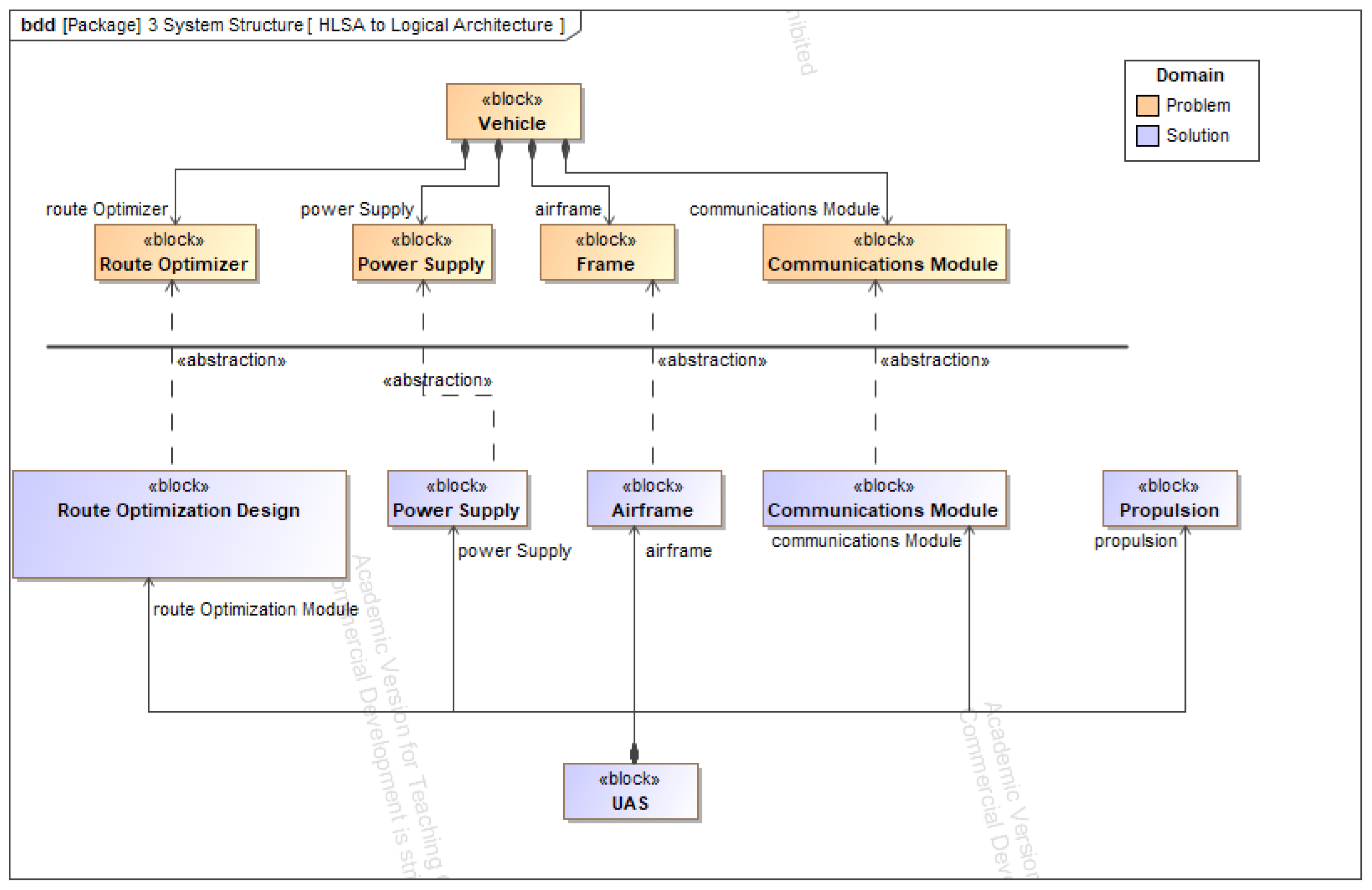
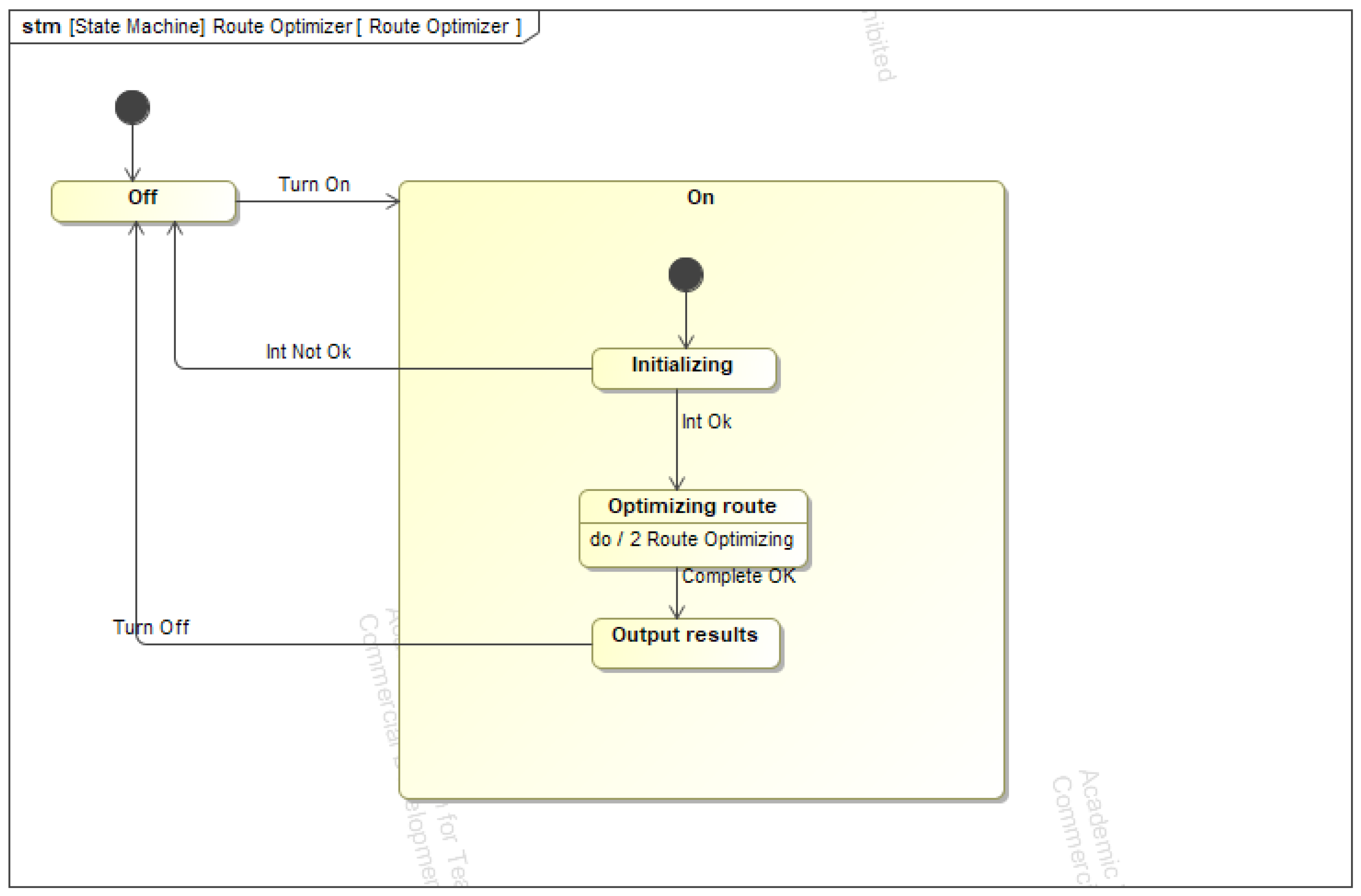
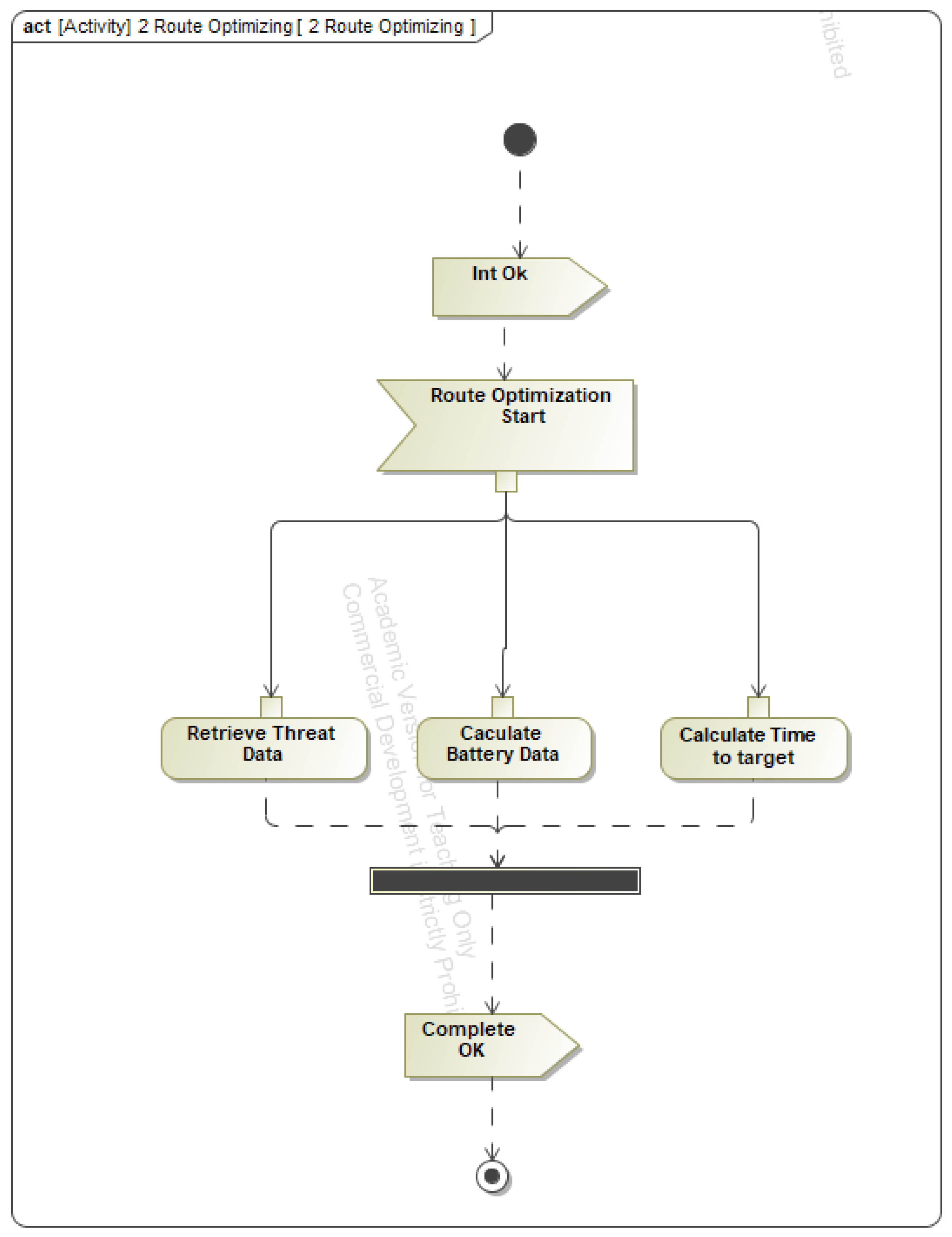
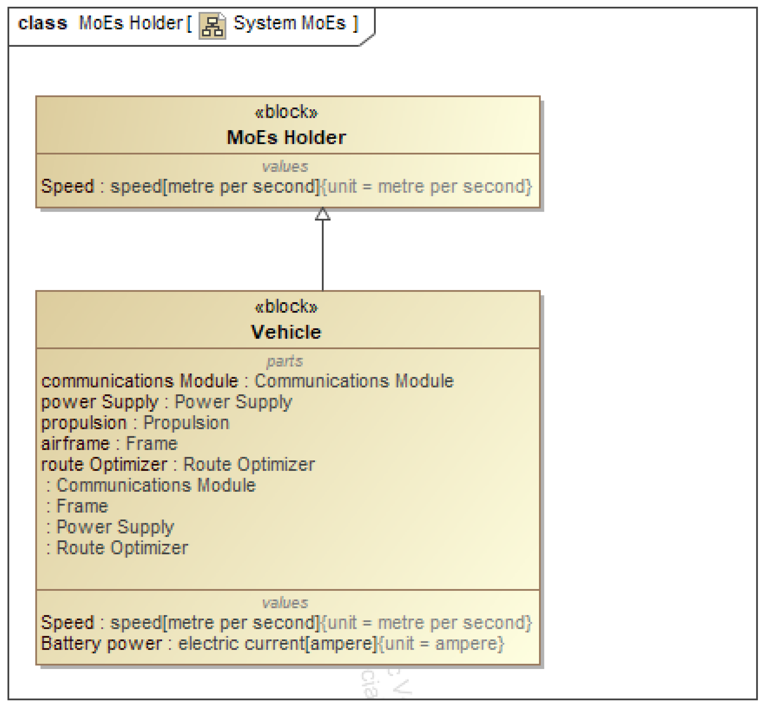
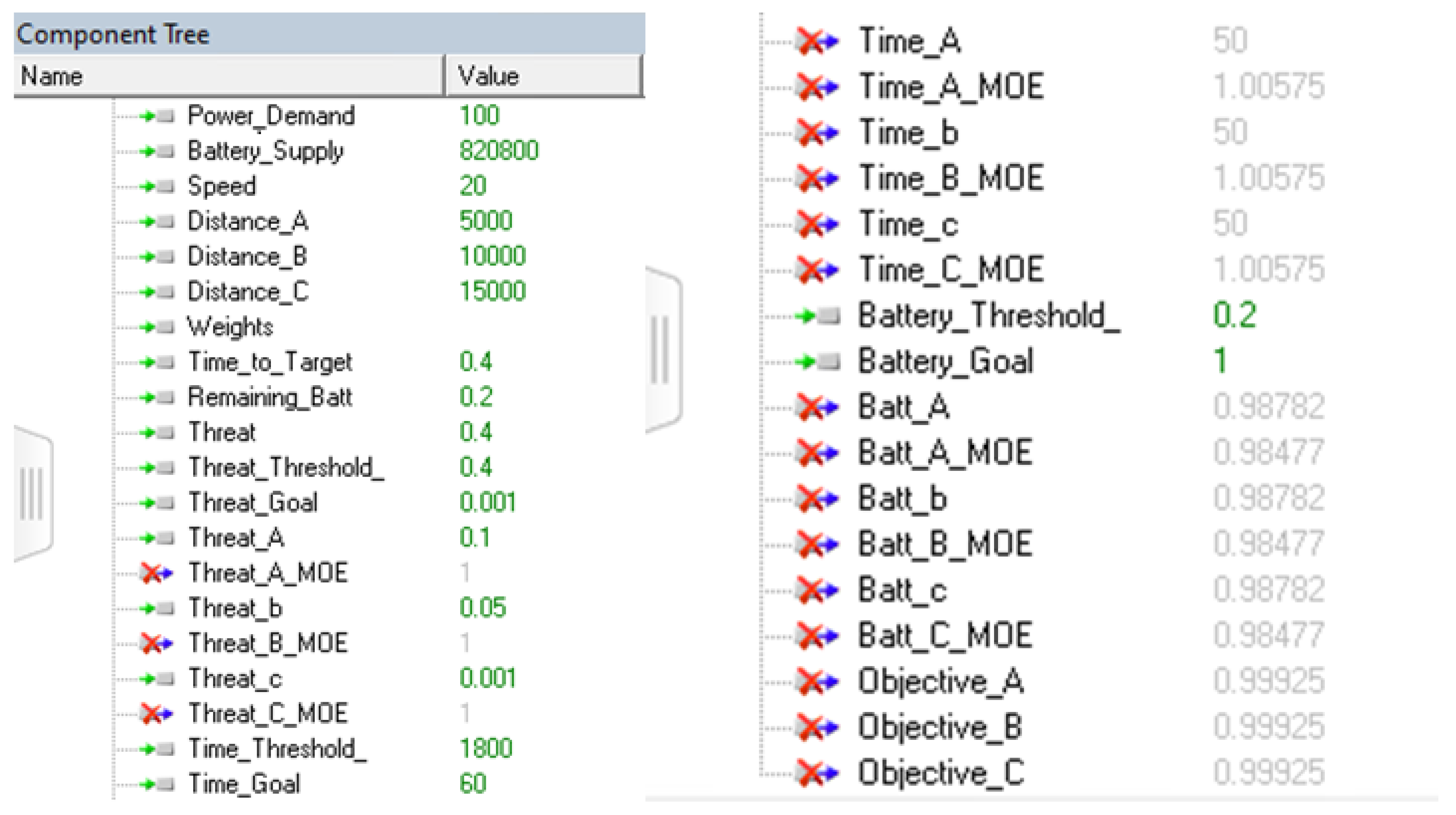
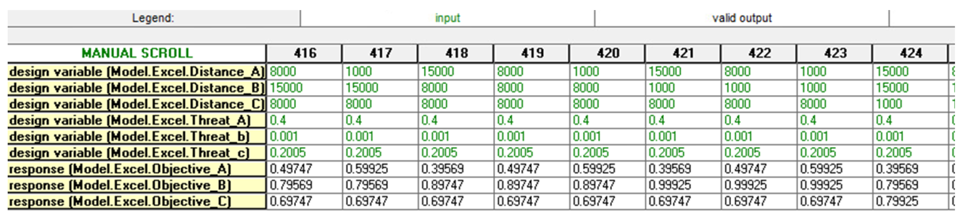
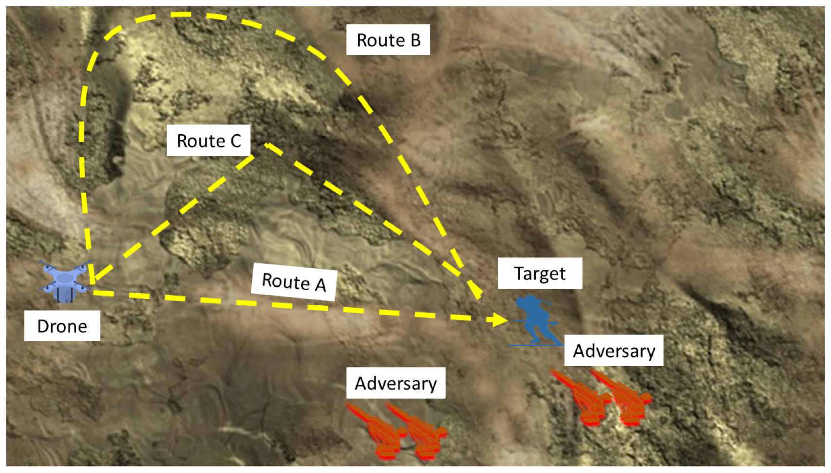
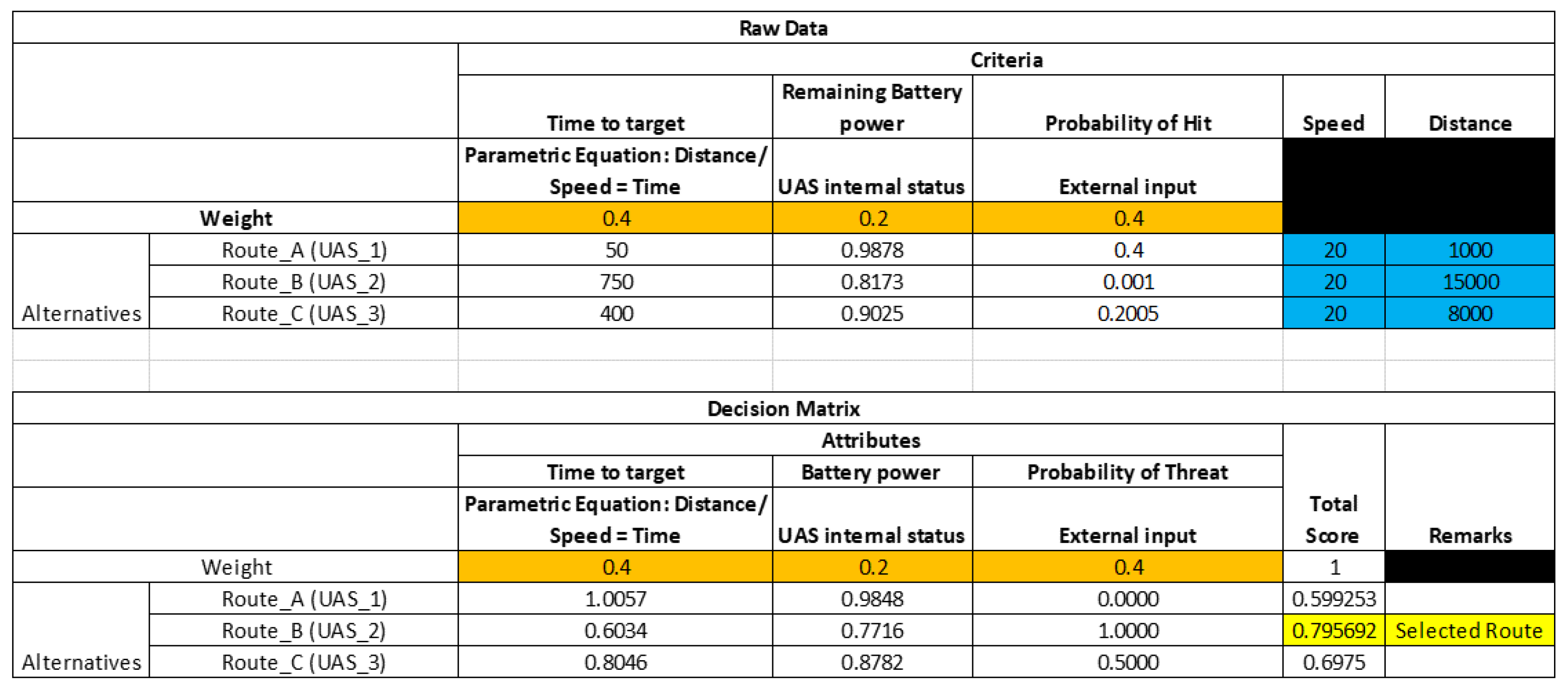
| Systems Engineering Process | ODTF Process | MagicGrid Process |
|---|---|---|
| Concept Exploration | Identify primary purpose | Stakeholder needs |
| Identify DT algorithm Identify DT data input types Identify location of DT | System requirements Component requirements | |
| Preliminary Design | Define DT architecture Define DT digital thread Integrate DT requirement into physical design | Use cases Functional analysis Component behavior System context Logical subsystem comms Component structure |
| Identify source data Identify data storage requirement | Not specifically covered | |
| Not specifically covered | Measure of Effectiveness Component parameter |
Table 2.
User-defined weightage for each of the criteria.
| Criteria | Risk-Attitude Weightage |
|---|---|
| Time to Target | 0.4 |
| Remaining battery power | 0.2 |
| Probability of Hit | 0.4 |
| Sum | 1.0 |
Publisher’s Note: MDPI stays neutral with regard to jurisdictional claims in published maps and institutional affiliations. |
© 2021 by the authors. Licensee MDPI, Basel, Switzerland. This article is an open access article distributed under the terms and conditions of the Creative Commons Attribution (CC BY) license (https://creativecommons.org/licenses/by/4.0/).
Share and Cite
MDPI and ACS Style
Lee, E.B.K.; Van Bossuyt, D.L.; Bickford, J.F. Digital Twin-Enabled Decision Support in Mission Engineering and Route Planning. Systems 2021, 9, 82. https://doi.org/10.3390/systems9040082
AMA Style
Lee EBK, Van Bossuyt DL, Bickford JF. Digital Twin-Enabled Decision Support in Mission Engineering and Route Planning. Systems. 2021; 9(4):82. https://doi.org/10.3390/systems9040082
Chicago/Turabian StyleLee, Eugene Boon Kien, Douglas L. Van Bossuyt, and Jason F. Bickford. 2021. "Digital Twin-Enabled Decision Support in Mission Engineering and Route Planning" Systems 9, no. 4: 82. https://doi.org/10.3390/systems9040082
Note that from the first issue of 2016, this journal uses article numbers instead of page numbers. See further details here.