Article

Thermoelectric Properties of N-Type Poly (Ether Ether Ketone)/Carbon Nanofiber Melt-Processed Composites

1
2C2T-Centre for Textile Science and Technology, Campus Azurem, University of Minho, 4800-058 Guimarães, Portugal
2
Leibniz-Institut für Polymerforschung Dresden e.V. (IPF), Hohe Str. 6, 01069 Dresden, Germany
3
CMEMS Research Center, Campus Azurem, University of Minho, 4800-058 Guimarães, Portugal
4
CICECO—Aveiro Institute of Materials, Department of Chemistry, University of Aveiro, 3810-193 Aveiro, Portugal
5
Facultad de Física, Pontificia Universidad Católica de Chile, Santiago 7820436, Chile
*
Author to whom correspondence should be addressed.
Polymers 2022, 14(22), 4803; https://doi.org/10.3390/polym14224803
Submission received: 11 October 2022 / Revised: 20 October 2022 / Accepted: 5 November 2022 / Published: 8 November 2022
(This article belongs to the Special Issue Carbon/Polymer Composite Materials)

Abstract

:
The thermoelectric properties, at temperatures from 30 °C to 100 °C, of melt-processed poly(ether ether ketone) (PEEK) composites prepared with 10 wt.% of carbon nanofibers (CNFs) are discussed in this work. At 30 °C, the PEEK/CNF composites show an electrical conductivity (σ) of ~27 S m−1 and a Seebeck coefficient (S) of −3.4 μV K−1, which means that their majority charge carriers are electrons. The origin of this negative Seebeck is deduced because of the impurities present in the as-received CNFs, which may cause sharply varying and localized states at approximately 0.086 eV above the Fermi energy level (EF) of CNFs. Moreover, the lower S, in absolute value, found in PEEK/CNF composites, when compared with the S of as-received CNFs (−5.3 μV K−1), is attributed to a slight electron withdrawing from the external layers of CNFs by the PEEK matrix. At temperatures from 30 °C to 100 °C, the σ (T) of PEEK/CNF composites, in contrast to the σ (T) of as-received CNFs, shows a negative temperature effect, understood through the 3D variable-range hopping (VRH) model, as a thermally activated hopping mechanism across a random network of potential wells. Moreover, their nonlinear S (T) follows the same behavior reported before for polypropylene composites melt-processed with similar CNFs at the same interval of temperatures.

1. Introduction

The electrical features of conductive polymer composites (CPCs) based on insulating polymers and carbonaceous materials have been extensively investigated since the end of the last century [1,2,3,4]. This is because the utilization of CPCs ranges from the high conductivities required for electromagnetic radiation shielding, electromagnetic interference (EMI), self-regulating heaters, and self-sensing materials [5] to the low conductivity of high dc-voltage cables and spacecraft components [6]. In this respect, carbon nanofibers (CNFs) produced by the chemical vapour deposition (CVD) of catalyst nanoparticles under gaseous hydrocarbons become very attractive among carbonaceous particles due to the combination of their interesting levels of conductivity (σ ~ 104 S m−1) and low-cost processes [7]. In morphologic terms, the CNFs produced by CVD exhibit tubular hollow cores surrounded by two or more outer layers of different ordered structure, with total diameters and lengths ranging from 50 to 200 nm and 50 to 100 µm, respectively [8,9]. On the other hand, it is convenient to establish direct relationships between the intrinsic electronic properties of carbonaceous materials, such as the electrical conductivity (σ) and Seebeck coefficient (S), and the resulting CPCs derived from them to optimize the final properties of the latter ones. In this light, the Seebeck coefficient (S), which shows the voltage generated by a semiconductor when subjected to a temperature difference, enables knowing the majority carrier type present in that semiconductor [10]. In short, n-type semiconductors have negative S and a majority of electrons, while p-type semiconductors have positive S and a majority of holes [11]. It should be remembered that the dominant charge carrier is an important property in semiconductors because it defines their ultimate use as components of energy-harvesting devices such as solar and thermoelectric cells [12]. For instance, thermoelectric generators (TEGs) typically consist of pairs of p- and n-type materials, while a solar cell is composed of p and n-type materials joined together, which is called the p-n junction.
It is in this respect that different contents of n-type CNFs are used in this work to prepare melt-processed poly(ether ether ketone) (PEEK) composites. The aim was to endow this insulating polymer matrix with electrical functionality and to achieve air stable n-type thermoelectric composites without the use of any type of complex doping strategy. PEEK is a thermoplastic polymer characterized by high melting and glass transition temperatures that presents excellent specific strength and corrosion resistance [13]. After preparing conductive PEEK/CNF composites using a simple, cost-effective and scalable melt-mixing procedure, a detailed analysis is performed by comparing the electronic properties (σ and S) of the as-received CNFs and the PEEK composites prepared with 10 wt.% of those CNFs. It is shown that the CNFs transfer their n-type character to the PEEK/10 wt.% CNF composites. Moreover, the PEEK/10 wt.% CNF composites showed lower σ and S (in absolute value) than the CNFs. In particular, the role of PEEK on the Seebeck coefficient of CNFs is examined by implementing a chemical model that measures the charge transfer existing between the outer graphitic shells of CNFs in contact with the PEEK chains [14]. Interestingly, a similar effect (slight p-type doping of carbon nanostructure by the PEEK matrix) has been observed in PEEK composites melt-processed with commercial multiwall carbon nanotubes (MWCNTs) NanocylTM NC7000 [15,16] and single-wall carbon nanotubes (SWCNTs) TuballTM [17]. In addition, quite unexpectedly, the electrical conductivity σ (T) of PEEK/10 wt.% CNF composites does not follow the σ (T) found in CNFs. That is, while the σ (T) of CNFs presents a reduction in electrical conductivity with temperature (positive temperature effect), the σ (T) of PEEK/10 wt.% CNF composites shows an increase in electrical conductivity with temperature (negative temperature effect). Finally, the cause of their n-type character is analysed through the modelling of S between 30 °C and 100 °C. All these outcomes are discussed in order to correlate the electronic properties of these PEEK/10 wt.% CNF composites processed with a conventional methodology with their potential use, a necessary practice for optimizing applications, which need of CPCs as building blocks. To our knowledge, the σ (T), S (T) analysis, and corresponding modelling presented here has not been discussed before for this particular type of CPCs.

2. Materials and Methods

2.1. Materials

A poly(ether ether ketone) powder VESTAKEEP® 1000P (Evonik Industries AG, Essen, Germany) with a melt volume flow rate of 150 cm3·10 min−1 (380 °C, 5 kg) and a density of 1300 kg·m−3 was used as polymer matrix. Carbon nanofibers (Pyrograf® III PR 24 LHT XT) supplied by ASI, Cedarville, OH, USA with bulk densities in the range of 0.016–0.048 g·cm−3 and lengths of 30–100 µm were chosen for processing melt-mixed PEEK-based composites with thermoelectrical properties. Pyrograf® III CNFs’ properties have been extensively investigated [18,19,20]. The CNF grade used in this study is grown at 1100 °C by CVD and thermally treated at 1500 °C in inert atmosphere after processing. At the end, the as-received CNFs show a hollow cylinder surrounded by an outer double-wall structure, as shown in Figure 1b.

2.2. Material Processing

The PEEK/CNF composites were melt mixed in a small-scale conical twin-screw microcompounder (Xplore Instruments BV, Sittard, The Netherlands) having a volume of 15 cm3. The polymer composites were mixed at 360 °C for 5 min with a rotational speed of 250 rpm. The CNFs and the polymer in powder form were alternatively filled into the main hopper of the compounder. The melt-mixed PEEK/CNF composite strands were then pelletized and compression-molded at 360 °C for 1 min with a hot press PW40EH (2 min preheating, max. force 50 kN, 0.5 min cooling in minichiller, polyimide foil as separation foil) to plates with diameter of 60 mm and thickness of ca. 0.3 mm. At the end, PEEK/CNF composites with CNF concentrations of 5, 7.5 and 10 wt.% were produced.

2.3. Morphological Analysis

The as-received CNFs were observed using ultra-high-resolution field emission gun scanning electron microscopy (FEG-SEM, NOVA 200 Nano SEM, FEI Company, Hillsboro, OR, USA) and a transmission electron microscope (TEM, JEOL JEM-2100) operating a LaB6 electron gun at 80 kV. TEM images were acquired with a “One-View” 4k × 4k CCD camera at minimal under-focus to achieve visibility of the CNF surface layers. Compression-moulded plates of the PEEK/CNF composite were cryo-fractured in liquid nitrogen and the surface was covered with 3 nm platinum before examining using a scanning electron microscope (SEM) (Ultra plus microscope, Carl Zeiss GmbH, Germany, field emission cathode) at 3 kV.

2.4. FTIR and DSC Analysis

Infrared measurements (FTIR, IRAffinity-1S, Shimadzu, Kyoto, Japan) were performed at room temperature in transmission mode from 600 to 2000 cm−1. FTIR spectra were collected with 40 scans and a resolution of 4 cm−1 at room temperature.
Differential scanning calorimetry measurements (DSC) were performed in argon atmosphere using a DSC Q20 instrument (TA Instruments, New Castle, DE, USA). The specimens were heated from 40 °C to 380 °C at a rate of 10 °C min−1 in nonisothermal experiments to eliminate any previous thermal history and then cooled down to 40 °C at a rate of 10 °C min−1. Following this analysis, the samples were heated to 380 °C at the same rate of 10 °C min−1.

2.5. Thermolectric Analysis

The Seebeck coefficient and volume resistivity of the PEEK/CNF composites and CNF powder were determined using the self-constructed equipment TEG at Leibniz-IPF [21,22]. A PVDF tube (inner diameter 3.8 mm, length 16 mm) filled with the CNF powder and closed with copper plugs was used for the thermoelectric measurements of the CNFs [16]. The PEEK/CNF samples were cut in strips of 15 mm × 4.5 mm and painted with conductive silver ink at their ends before testing. The thermovoltage and electrical resistance were performed using the Keithley multimeter DMM2001 (Keithley Instruments, Cleveland, OH, USA) with a free insert length of 12 mm between the two copper electrodes. The volume resistivity was measured using a 4-wire technique. The conductivity values represent the arithmetic means of ten measurements on two strips. The measurements of S were performed on the same strips at the mean temperatures of 30 °C (303.15 K), 40 °C, 60 °C, 80 °C, and 100 °C (373.15 K) by applying temperature differences between the two copper electrodes up to ±8 K around the mean temperature in 2 K steps. The Seebeck coefficient at each temperature was calculated as the average of eight thermoelectric voltage measurements. This measurement was repeated 3 times, and the means are reported. The samples containing 5 and 7.5 wt.% CNF were not conductive enough to perform measurements of the Seebeck coefficients. Thus, Seebeck coefficients are not reported for them. In particular, their electrical volume conductivities were 8 × 10¹⁵ Ohm·cm and 2 × 10⁷ Ohm·cm, respectively (measured with a Keithley 8009 Resistivity Test Fixture combined with electrometer Keithley E6517A).

2.6. Thermal Conductivity

The thermal conductivity (k) of the PEEK/10 wt.% CNF composites was calculated from the product of thermal diffusivity, density, and specific heat capacity. The thermal diffusivity was measured on circular samples (diameter 12.5 mm, thickness 1.8 mm) through the plate thickness using the light flash apparatus LFA 447 NanoFlash (Netzsch-Gerätebau GmbH, Selb, Germany) at 30 °C (303.15 K), 40 °C, 60 °C, 80 °C, and 100 °C (373.15 K). The specific heat capacity was calculated by comparing the signal heights between the PEEK/10 wt.% CNF composite and the reference Pyroceram 9606 (with known specific heat capacity) using the LFA 447 NanoFlash software. The density of the PEEK/10 wt.% CNF composite was determined using the buoyancy method. The given values represent the means of four measurements.

2.7. Electronic Charge Transfer Modeling

The contact charge transfer between the PEEK chains and the external graphitic shells of CNFs outlined by the hexagonal graphene flake shown in Figure 2 was computed following on previous studies [14,23]. For this, the molecular geometry and the charge transfer of PEEK oligomers with up to three monomers adding up to a total length of 4.6 nm adsorbed on a graphene flake of 5.6 nm diameter and 912 atoms were optimized. The calculations were performed with the GFN1-xTB (G: geometries; F: frequencies; N: noncovalent interaction) tight-binding model, which allows for computing systems with thousands of atoms [24], while the charge transfer was computed by adding up the CM5 partial charges produced by the same Hamiltonian [25] on the PEEK oligomer and hexagonal graphene flake.

3. Results and Discussion

3.1. Morphological Analysis

Figure 1 shows representative SEM and TEM images of CNFs. As shown in Figure 1b, the CNF diameter is of ~90 nm, which matches well with the mean diameters measured in previous works for the same type of CNFs [14,20]. The single CNF presents a straight and cylindrical hollow tube of around 42 nm with a surrounding double structure (Figure 1b). The inner part of the double layer shows an arrangement of compacted graphitic layers with a total thickness of ~7.4 nm. The outer part of the double layer shows a larger size of ~15.8 nm, and it is composed of graphitic sheets, though their morphology is not as perfect and compacted as that observed in the inner layer [14,23]. Figure 3 shows representative SEM images of the PEEK/CNF 10 wt.% composite at different magnifications. The images reveal a homogeneous distribution and dispersion of CNFs within the PEEK without the presence of CNF agglomerates. Moreover, most of CNFs do not protrude far above the poly(ether ether ketone) fracture surface, which is an indication that the interfacial bonding between CNFs and the PEEK appears to be strong [26].

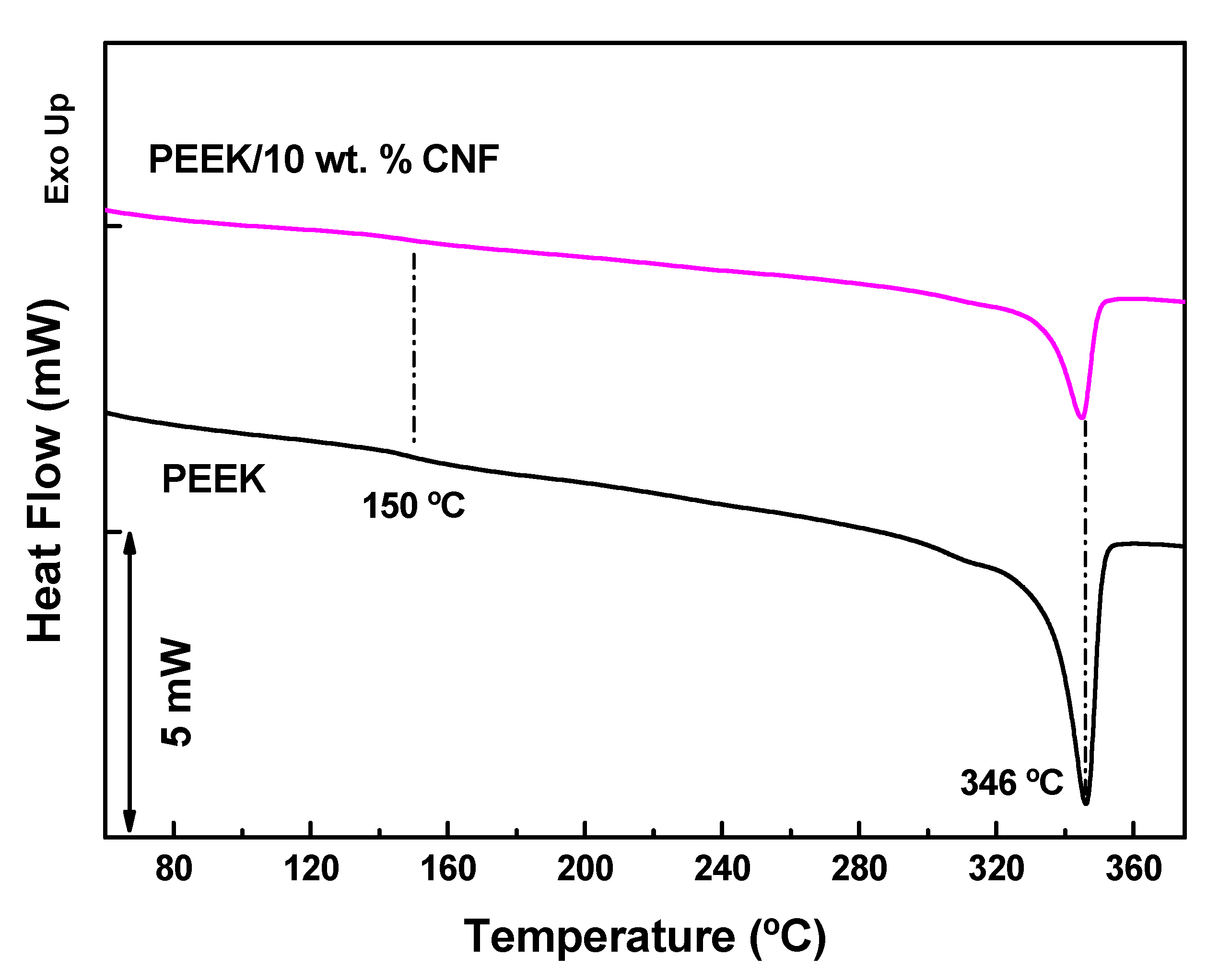
3.2. FTIR and DSC Analysis

Figure 4 presents the FTIR spectrum at room temperature of the neat PEEK and the PEEK filled with 10 wt.% CNFs in the 600–1800 cm−1 range. The PEEK spectra show a carbonyl stretching vibration at 1645 cm−1 and skeletal ring vibrations at 1590 cm−1, 1487 and 1410 cm−1. The bending motion of C−C and (=O)−C groups appeared at around 1305 cm−1. The asymmetric stretching vibration bands of the diphenyl ether group appeared at 1278 cm−1 and 1184 cm−1 [27], whereas the peak at 1154 cm−1 corresponds to C−O−C stretching [28]. The peak at 1010 cm−1 is ascribed to the C–H in-plane bending vibration absorption band of the benzene ring. Absorbance at wave numbers 925 cm−1 to 670 cm−1 corresponds to C-H out of the plane bend vibrations [29]. The PEEK/10 wt.% CNF composites show a general decrease in the neat PEEK peak intensities, suggesting a decrease in PEEK chain mobility with the addition of CNFs.
The DSC analyses shown in Figure 5 were conducted to gain information about the effect of CNFs on the crystallization of PEEK, which is expected to influence the electrical properties of PEEK/10 wt.% CNF composites. In particular, the melting temperature (Tm) and degree of crystallinity (ΔXc) in % of PEEK and PEEK/10 wt.% CNF composites related to the second heating scans were calculated by:
Δ X C = Δ H m Δ H 0 f PEEK × 100 %
Here ΔHm is the melting enthalpy of the PEEK part and ΔH0fPEEK is the melting enthalpy of the 100% crystalline PEEK (130 J g−1) [30]. The corresponding values of Tm, ΔHm and ΔXc are shown in Table 1. The subtle decrease in the heat flux curves in Figure 5 observed at 150 °C has to correspond to the glass transition temperature (Tg) of PEEK [28]. This Tg is even more difficult to detect in PEEK/10 wt.% CNF composites. PEEK shows a clear melting peak at ~346 °C in accordance with other works [26], while PEEK/10 wt.% CNF composite shows a slightly lower melting temperature of ~345 °C. This practically unchanged Tm is also in agreement with previous works [26]. The results of Equation (1) show a slight decrease in ΔXc from 35% corresponding to PEEK to 28% for PEEK/10 wt.% CNF composites. A similar slight reduction in ΔXc was already reported for PEEK/CNF composites [26]. However, this finding is in contrast to CNFs dispersed in polypropylene (PP) [31]. In that study, the same type of CNFs (Pyrograf® III PR 24 LHT XT) act as nucleation sites of PP, evidenced by a significant ΔXc increase from 38% of unfilled PP to 50% in PP/CNF composites with 0.9 vol % of CNFs.

3.3. Thermoelectric Properties of PEEK/CNF Composites at 30 °C

The thermoelectric properties (σ and S) at 30 °C (303.15 K) of the CNF powder and PEEK/10 wt.% CNF composites are presented in Figure 6. The CNF powder shows an σ of 133.5 ± 0.4 S m−1 (Table 2). Thus, the σ of the CNF powder used in this study (Pyrograf® III PR 24 LHT XT) is comparable with the σ of 136.4 S m−1 reported for CNF powder (Pyrograf® III PR 19 LHT XT) [32]. As expected, the σ of PEEK/10 wt.% CNF composites (27.5 ± 0.1 S m−1) is significantly less than the σ of the CNF powder. This significant difference is attributed to the wrapping of PEEK chains around the CNFs, which must increase the contact electrical resistance between the adjacent CNFs, resulting in the decrease in the CNF network conductivity [33]. It must be noted that the composite with 5 wt.% was not conductive by showing nearly the same conductivity as the pure PEEK. The σ of PEEK/7.5 wt.% CNF composite achieves a value of 5 × 10⁻⁶ S m−1 at 30 °C and therefore the PEEK/10 wt.% CNF composite analysed can be considered well above the electrical percolation threshold. In comparative terms, the σ of PEEK/10 wt.% CNF composite (27.5 S m−1) is higher than the values of σ achieved in melt-mixed composites of PEEK and 10 wt.% of MWCNTs [34,35]. However, a high σ of 65 S m−1 has been recently reported for melt-mixed composites of PEEK and 5 wt.% single-walled carbon nanotubes (SWCNTs) [17].
The Seebeck coefficients of the CNF powder and PEEK/10 wt.% CNF composite at 30 °C are also shown in Figure 6 and Table 2. The CNF powder shows n-type character, with S of −5.3 ± 0.1 μV K−1. It can be noticed that the S-value obtained (−5.3 μV K−1) is very similar to the −5.1 μV K−1 reported for the Pyrograf® III CNF PR 19 LHT XT grade [32]. On the other hand, the S of PEEK/10 wt.% CNF composite (presented as red triangles in Figure 6) shows also a negative S-value of −3.4 ± 0.1 μV K−1 (Table 2). Therefore, the presence of these CNFs imparts n-type character to the PEEK/10 wt.% CNF composite, though the latter one present less negative S-values compared with as-received CNFs. In order to investigate the role of PEEK in these results, adsorbed PEEK oligomers on an idealized external graphene CNF flake were modelled as described in previous Section 2.7. The model reveals a charge transfer of approximately 0.02 eV/monomer from graphene to the PEEK oligomers in all modelled cases. This matches well with a similar finding observed on melt-mixed PP/CNF composites [14]. Furthermore, the computed total charge transfer for a comparable-length PP polymer is of a similar magnitude to what is obtained here for PEEK under similar conditions. According to this model, a slight electron withdrawing from the CNF outer layers by the PEEK molecules is expected, which would justify the lower S (absolute value) found in PEEK/CNF 10 wt.% composites.
From this conclusion, the same type of electron withdrawing by the PEEK matrix of other carbon structures such as carbon nanotubes (CNTs) is expected, as shown in previously studied PEEK/CNT composites with p-type character [15,17]. For example, the Seebeck coefficient measured for melt-mixed composites PEEK/SWCNT composites (0.5–1.25 wt.% SWCNT of the type TuballTM) [17] was higher than that of pure SWCNT powder [16]. Likewise, the values measured for PEEK composites with 3 and 5 wt.% MWCNTs of the type Nanocyl™NC 7000 [17] are also higher than those of the MWCNTs [16], and the same applies for PEEK composites with 0.5 to 3 wt.% MWCNTs of the type CNS-PEG [16,17]. In a different work, it was also found that a melt-mixed PEEK composites with 3 and 4 wt.% MWCNTs (Nanocyl™ NC 7000 type) [15] led to higher S-values than the starting MWCNT material [16]. In summary, all these findings indicate that also in PEEK composites with CNTs, the PEEK matrix induces an electron withdrawing from the CNTs, which are forming the electrically conductive network and are responsible for the Seebeck effect.
The power factor PF ( S 2 σ ) at 30 °C of the PEEK/10 wt.% CNF composite and CNF powder was calculated, and the results are shown in Table 2. The CNF powder shows a PF of 3.7 × 10⁻³ μW·m−1·K−2, whereas the PEEK/10 wt.% CNF composite achieves a PF of 3.1 × 10⁻⁴ μW·m−1·K−2, which is slightly higher than the PF of 1.8 × 10⁻⁴ obtained in PP/CNF composites with 5 wt.% of Pyrograf® III PR 19 LHT XT CNFs [32]. These values are one order of magnitude lower than the values of 1.0 × 10⁻³ μW·m−1·K−2 obtained in melt-mixed PEEK composites prepared with 4 wt.% MWCNTs [15]. It has to be noted that PF of 2.0 × 10⁻² has been reported for melt-mixed composites of PEEK with 1.25 wt.% SWCNTs [17]. The conductivity, Seebeck coefficient, and power factor of all these carbon materials and their melt-processed PEEK composites are conveniently summarised in the Supplementary Table S1.
Finally, the figure of merit ( zT = S 2 σ k   T ) at 30 °C of the CNF powder was calculated using the thermal conductivity of 0.43 W m−1 K−1 reported on anisotropic paper-like mats of Pyrograf®-III CNFs [36]. The zT of PEEK/10 wt.% CNF composites was calculated from the thermal conductivity tested as described in Section 2.5. The estimated zT of the CNF powder presented a value of 2.6 × 10⁻⁶ (Table 2), while a lower zT of 2.3 × 10⁻⁷ was calculated for PEEK/CNF 10 wt.% composites, which is similar to the zT of 2.2 × 10⁻⁷ obtained in PP/CNF composite with 5 wt.% of Pyrograf® III PR 19 LHT XT CNFs [32]. In comparative terms, the zT calculated for PEEK/CNF composites is one order of magnitude lower than the zT of ~4 × 10⁻⁶ at 40 °C reported for PEEK composites filled with 4 wt.% of MWCNTs and 3 wt.% of graphite nanoplates [15].

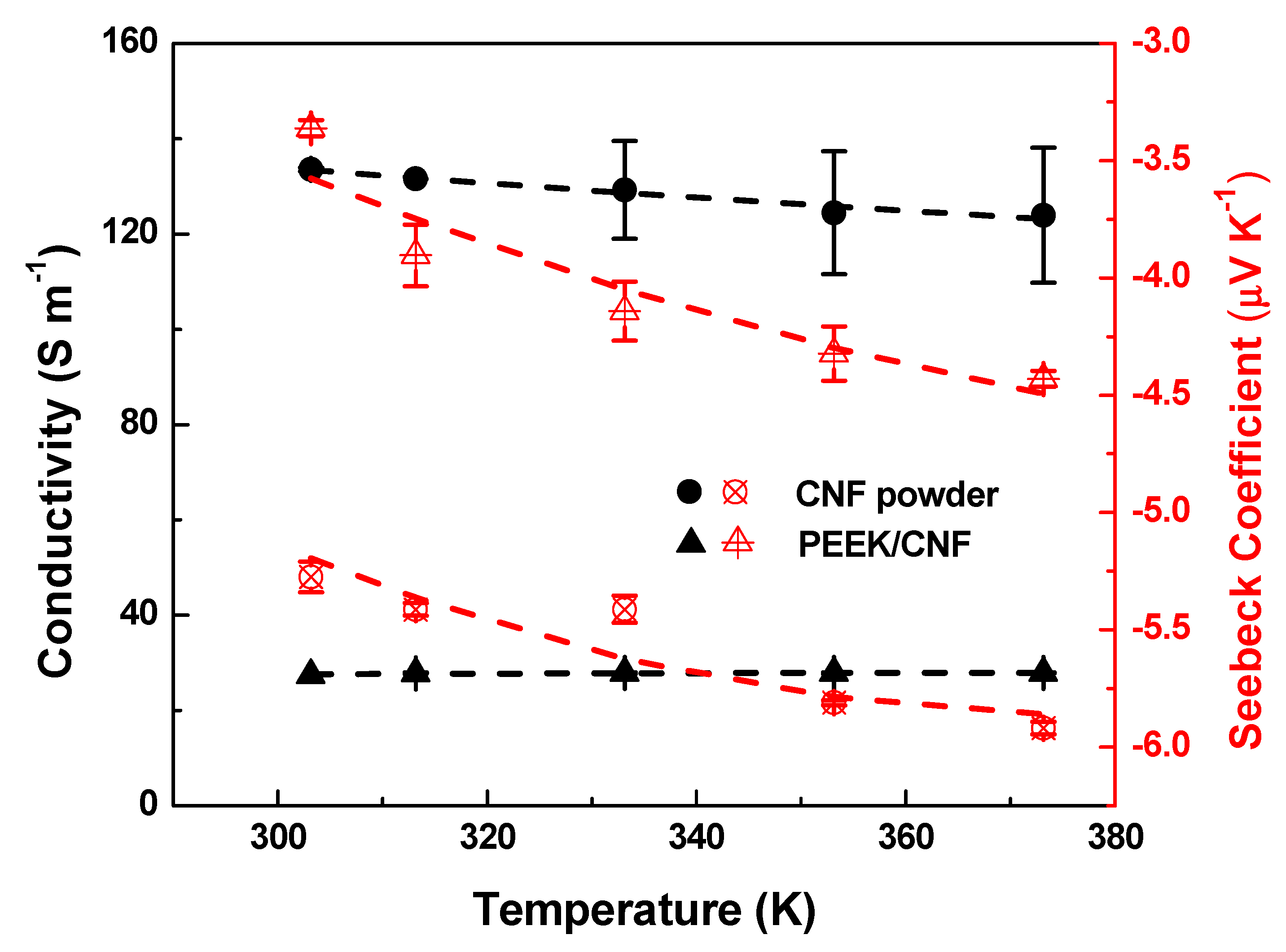
3.4. Thermoelectric Analysis of PEEK/CNF Composites from 30 °C to 100 °C

The thermoelectric properties σ(T) and S(T) from 30 °C (303 K) to 100 °C (373 K) of the CNF powder and PEEK/10 wt.% CNF composites are also analysed in this study (Figure 6). As was previously noted, σ of 133.5 ± 0.4 S m−1 is obtained for the CNF powder at 30 °C, which decreases up to 123.9 ± 14.1 S m−1 at 100 °C (Table 3). Thus, the σ (100 °C) value of the CNF powder used in this study (Pyrograf® III PR 24 LHT XT) is comparable to the σ (100 °C) of 127 S m−1 reported for CNF powder (Pyrograf® III PR 19 LHT XT) [32]. Interestingly, the CNF powder shows a slight positive temperature effect (dσ/dT < 0) as it was observed for Pyrograf® III PR 19 LHT XT CNF powder over the same interval of temperatures [32]. In this regard, it is noted that CNTs usually present a negative temperature effect (dσ/dT > 0) [37,38,39]. In contrast to the σ (T) of the CNF powder, the PEEK/10 wt.% CNF composite shows a very slight negative temperature effect from ~27.5 ± 0.1 S m−1 at 30 °C to ~27.9 ± 0.1 S m−1 at 100 °C (black triangle icons in Figure 6), which is consistent with results in other articles [40,41]. Therefore, the σ (T) of PEEK/10 wt.% CNF composite does not follow the same σ (T) found in the CNF powder. In other words, the PEEK matrix should play its role on the σ (T) of PEEK/CNF composites. This finding is in contrast to previous work [32], where the σ (T) of both the PP/5 wt.% CNF composite and the corresponding CNFs showed a positive temperature effect.
The S (T) of the CNF powder is also presented as red circle icons in Figure 6. The n-type character of the CNF powder found at 30 °C keeps negative at all temperatures. In particular, the CNF powder presents a S-value of −5.3 ± 0.1 μV K−1 at 30 °C, which increases gradually (in absolute value) up to −5.9 ± 0.1 μV K−1 at 100 °C (Table 3). It must be noticed that the S-value obtained here at 100 °C is very similar to the value of −5.8 μV K−1 reported for the Pyrograf® III CNF PR 19 LHT XT grade at 100 °C [32]. Based on the experimental values presented here, it can be concluded that both Pyrograf® III grades (PR 19 LHT XT and PR 24 LHT XT) present similar σ (T) and S (T) in the interval of 30−100 °C. On the other hand, the S (T) of PEEK/10 wt.% CNF composite (red triangle icons in Figure 6) shows S-values from −3.4 ± 0.1 μV K−1 at 30 °C to −4.4 ± 0.1 μV K−1 at 100 °C (Table 3). Therefore, the S (T) of the PEEK/10 wt.% CNF composite, similarly to the S (T) of the CNF powder, shows negative S-values gradually increasing (in absolute value) with temperature.
The power factor PF as function of temperature of the PEEK/10 wt.% CNF composite and CNF powder was calculated, and the results are shown in Table 3. At 100 °C, the CNF powder achieves a value of 4.3 × 10⁻³ μW·m−1·K−2, whereas the PEEK/10 wt.% CNF composite achieves a PF of 5.5 × 10⁻⁴ μW·m−1·K−2. Thus, this PF is slightly higher than the PF of 2.6 × 10⁻⁴ obtained at 100 °C in PP/CNF composite with 5 wt.% of Pyrograf® III PR 19 LHT XT CNFs [32]. The figure of merit zT of PEEK/10 wt.% CNF composite increases slightly from 2.3 × 10⁻⁷ (30 °C) up to 4.7 × 10⁻⁷ (100 °C) despite the slight increase in the thermal conductivity with temperature (Table 3). A similar zT of 4.4 × 10⁻⁷ at 100 °C was found in PP/CNF composite with 5 wt.% of Pyrograf® III PR 19 LHT XT CNFs [32].

3.5. Electronic Modelling of PEEK/CNF Composites

Similar to the previous work [32], the 3D variable-range hopping (VRH) model is applied to evaluate the σ (T) of the CNF powder and PEEK/10 wt.% CNF composite [42,43]:
σ ( T ) = σ 0     exp [ ± ( T C T )   1 4   ]
Here σ0 is the conductivity at an infinite temperature, and T C   | W D | k B is a characteristic temperature scale determined by the average energy potential barrier (WD < 0) or potential well (WD > 0), respectively, and kB is the Boltzmann’s constant. It is important to notice that when WD > 0, Equation (2) describes a thermally activated hopping mechanism across a random network of potential wells, leading to a typical dσ/dT > 0, while when WD < 0, Equation (2) describes a thermally activated scattering mechanism across a random distribution of impurities or structural defects, leading to a typical dσ/dT < 0. Values of   σ 0 = 27.60   S   m 1 , T C = 1.87 × 10 3   K , and W D = 160   meV as shown in Table 4 are calculated from Equation (2) for the CNF powder. Thus, it is deduced that the parameters σ0, TC and WD of this Pyrograf® III grade (PR 24 LHT XT) are comparable with the σ0, TC and WD calculated by the VRH model for Pyrograf® III PR 19 LHT XT [32]. Interestingly, TC (1.9 × 10³ K) is one order of magnitude higher than that of some reported SWCNT mats (2.5 × 10² K) [44]. The WD (absolute value) for the CNF powder (160 meV) is one order of magnitude higher than the activation energy (60 meV) reported for n-type graphitized carbon fibres in the 250–750 K interval [45]. Similar to the previous work [32], the CNF powder used in this study shows negative WD. This finding, which is not usual in carbon nanostructures [43,46,47], can be explained by the presence of impurities, such as the oxygen detected by X-ray photoelectron spectroscopy (XPS) in the same type of Pyrograf® III CNFs [23,48,49]. These impurities could activate a thermal-enhanced backscattering mechanism due to the presence of virtual bound-states, represented as sharp peaks near the EF in the density of states [46,50].
The σ (T) of PEEK/10 wt.% CNF composites was also studied with the 3D VRH model, from which   σ 0 = 33.8   S   m 1 ,   T C = 0.5   K , and W D = + 4.3 × 10 2   meV were obtained. Thus, as can be seen in Table 4, the TC obtained for the PEEK/10 wt.% CNF composite is very different (four orders of magnitude lower) than the TC (1.9 × 10³ K) of the CNF powder. Notably, the WD of PEEK/10 wt.% CNF composite is now positive. These results imply that the σ (T) of PEEK/10 wt.% CNF composite is not dominated by the thermally activated backscattering mechanism responsible for the negative WD found in the CNF powder. Thus, the σ (T) of PEEK/10 wt.% CNF composite can be understood as the e overcoming by hopping in a random network of potential wells [43,49,51].
The S (T) of the CNF powder and PEEK/10 wt.% CNF composite is depicted by the same model proposed for describing the nonlinear S(T) of polypropylene composites melt-processed with similar CNFs (PR 19 LHT XT) [32]:
S   ( T ) = bT + cT p T 2 exp ( T P T ) [ exp ( T P T ) + 1 ] 2
Here, bT represents the metallic (linear) term, c is a constant, and T p = ( E p E F ) / k where kB is Boltzmann’s constant, EF is the Fermi energy level, and EP is the energy corresponding to the sharply varying and localized states near EF in the density of states due to the contribution of impurities [46,50]. The best fit of S(T) with Equation (3) for the CNF powder (Figure 6) shows that the first term b is positive with 5.1 × 10 3   μ V   K 2 , while the second term c is negative with 1.8 × 10 4   μ V   and T p = 997.42   K , yielding a E P   E F = 0.086   eV . The negative sign of c can be physically interpreted as the resonances near the EF at the density of states caused by impurities present in the CNF structure [46]. As expected from the experimental S(T) values (Table 3), the b, c, TP and E P   E F   values obtained by Equation (3) for this Pyrograf® III grade (PR 24 LHT XT) are very similar to the b, c, TP and E P   E F   values calculated by the same model for Pyrograf® III PR 19 LHT XT [32] (Table 5). Likewise, the S (T) of PEEK/10 wt.% CNF composite is also fitted by Equation (3) with the best fit resulting in b = 1.85 × 10 4   μ V   K 2 , c = 1.25 × 10 4   μ V , T p = 1117.6   K , and E P   E F = 0.096   eV . As shown in Table 5, the fittings obtained by Equation (3) for PEEK/10 wt.% CNF are very similar to parameters calculated for the CNF powder. Thus, it can be deduced that in contrast to σ (T), the S (T) of CNF powder clearly drives the S (T) of PEEK/10 wt.% CNF composite.

4. Conclusions

The electrical conductivity (σ) and Seebeck coefficient (S) between 30 °C and 100 °C of as-received carbon nanofibers (CNFs) and melt-processed PEEK/10 wt.% CNF composites are analysed. At 30 °C, the σ, S, and power factor (PF) of the CNFs are ~133 S m−1, −5.3 μV K−1, and 3.7 × 10⁻³ μWm−1 K−2, respectively. The PEEK/10 wt.% CNF composite shows lower conductivity and S of 27.5 S m−1 and −3.4 μV K−1, respectively, corresponding to a PF of 3.1 × 10⁻⁴ μWm−1 K−2. As the CNFs, the prepared PEEK/CNF composites are n-type materials with e as dominant charge carriers, and the origin of their n-type character is explained by the presence of impurities in the CNFs, which could produce sharp peaks close to the Fermi energy level (EF) of CNFs. The less negative value of S in the PEEK/CNF 10 wt.% composite when compared with the as-received CNFs is rationalized with the help of quantum chemical computer models and attributed to an electron-withdrawing effect arising from the PEEK molecules in contact with the most external graphene layers of CNFs. Moreover, in contrast to the slight positive temperature effect of σ found in the as-received CNFs, the σ (T) of PEEK/CNF 10 wt.% composite from 30 °C to 100 °C shows a very slight negative temperature effect. Thus, it is concluded that the σ (T) of the latter does not follow the same σ (T) found in CNF powder, and thereby the presence of PEEK must play a predominant role in their mechanism conduction. This fact is better understood through the 3D variable-range hopping model of the σ (T) in PEEK/CNF 10 wt.% composite, which points towards the e overcoming in a random network of potential wells by hopping. In addition, the S (T) of PEEK/CNF 10 wt.% composite from 30 °C to 100 °C presents a negative temperature effect, as does the S (T) of the CNFs for the same range of temperature, which was analysed using the same model proposed for describing the nonlinear S(T) of melt-processed polypropylene/CNF composites.

Supplementary Materials

The following supporting information can be downloaded at: https://www.mdpi.com/article/10.3390/polym14224803/s1, Table S1: Thermoelectric properties of carbon nanotube and carbon nanofiber powders and their melt-processed PEEK composites.

Author Contributions

All authors of this manuscript contributed to the development of this work. A.J.P. contributed with writing—original draft, investigation, conceptualization. B.K. and P.P. contributed with investigation, resources, validation, methodology, writing—review. D.S. contributed with resources. E.M. contributed with electronic modelling, and writing—review. M.M.-F. contributed with the charge transfer modelling, and writing—review. A.M.R. was responsible of project funding. All authors have read and agreed to the published version of the manuscript.

Funding

A. J. Paleo gratefully acknowledges support from FCT-Foundation for Science and Technology by the project UID/CTM/00264/2021 of 2C2T under the COMPETE and FCT/MCTES (PIDDAC) co-financed by FEDER through the PT2020 program and “plurianual” 2020–2023 Project UIDB/00264/2020. E. Muñoz acknowledges financial support from ANID Anillo ACT/192023 and Fondecyt No 1190361. M. Melle-Franco acknowledges support from the project IF/00894/2015 and within the scope of the project CICECO-Aveiro Institute of Materials, UIDB/50011/2020, UIDP/50011/2020 & LA/P/0006/2020, financed by national funds through the FCT/MEC (PIDDAC).

Institutional Review Board Statement

Not applicable.

Informed Consent Statement

Not applicable.

Data Availability Statement

The authors confirm that the data supporting the findings of this study are available within the article.

Acknowledgments

The authors would like to thank the collaborators of the IPF research technology department for their support in designing and building the thermoelectric equipment including the software and Manuela Heber (IPF) for taking SEM images.

Conflicts of Interest

The authors declare no conflict of interest.

References

  1. Foulger, S.H. Electrical properties of composites in the vicinity of the percolation threshold. J. Appl. Polym. Sci. 1999, 72, 1573–1582. [Google Scholar] [CrossRef]
  2. Jing, X.; Zhao, W.; Lan, L. The effect of particle size on electric conducting percolation threshold in polymer/conducting particle composites. J. Mater. Sci. Lett. 2000, 19, 377–379. [Google Scholar] [CrossRef]
  3. Knite, M.; Teteris, V.; Aulika, I.; Kabelka, H.; Fuith, A. Alternating-current properties of elastomer-carbon nanocomposites. Adv. Eng. Mater. 2004, 6, 746–749. [Google Scholar] [CrossRef]
  4. Logakis, E.; Pandis, C.; Peoglos, V.; Pissis, P.; Pionteck, J.; Pötschke, P.; Mičušík, M.; Omastová, M. Electrical/dielectric properties and conduction mechanism in melt processed polyamide/multi-walled carbon nanotubes composites. Polymer 2009, 50, 5103–5111. [Google Scholar] [CrossRef]
  5. Bhadra, S.; Rahaman, M.; Noorunnisa Khanam, P. Electrical and Electronic Application of Polymer–Carbon Composites. In Carbon-Containing Polymer Composites; Rahaman, M., Khastgir, D., Aldalbahi, A.K., Eds.; Springer Singapore: Singapore, 2019; pp. 397–455. [Google Scholar]
  6. Azizi, S.; David, E.; Fréchette, M.F.; Nguyen-Tri, P.; Ouellet-Plamondon, C.M. Electrical and thermal phenomena in low-density polyethylene/carbon black composites near the percolation threshold. J. Appl. Polym. Sci. 2019, 136, 47043. [Google Scholar] [CrossRef]
  7. Hansora, D.P.; Shimpi, N.G.; Mishra, S. Performance of hybrid nanostructured conductive cotton materials as wearable devices: An overview of materials, fabrication, properties and applications. RSC Adv. 2015, 5, 107716–107770. [Google Scholar] [CrossRef]
  8. Burton, D.J.; Glasgow, D.G.; Lake, M.L.; Kwag, C.; Finegan, J.C. In Influence of carbon nanofibers surface characteristics on composite properties. In Proceedings of the 46th International SAMPE Symposium and Exhibition, Long Beach, CA, USA, 6–10 May 2001; p. 647. [Google Scholar]
  9. Gordeyev, S.A.; Macedo, F.J.; Ferreira, J.A.; van Hattum, F.W.J.; Bernardo, C.A. Transport properties of polymer-vapour grown carbon fibre composites. Phys. B 2000, 279, 33–36. [Google Scholar] [CrossRef]
  10. Zieleniewska, A.; Lodermeyer, F.; Prato, M.; Rumbles, G.; Guldi, D.M.; Blackburn, J.L. Elucidating the electronic properties of single-wall carbon nanohorns. J. Mater. Chem. C 2022, 10, 5783–5786. [Google Scholar] [CrossRef]
  11. Zevalkink, A.; Smiadak, D.M.; Blackburn, J.L.; Ferguson, A.J.; Chabinyc, M.L.; Delaire, O.; Wang, J.; Kovnir, K.; Martin, J.; Schelhas, L.T.; et al. A practical field guide to thermoelectrics: Fundamentals, synthesis, and characterization. Appl. Phys. Rev. 2018, 5, 021303. [Google Scholar] [CrossRef]
  12. Chen, G.; Li, Y.; Bick, M.; Chen, J. Smart Textiles for Electricity Generation. Chem. Rev. 2020, 120, 3668–3720. [Google Scholar] [CrossRef]
  13. Mokhtari, M.; Archer, E.; Bloomfield, N.; Harkin-Jones, E.; McIlhagger, A. A review of electrically conductive poly(ether ether ketone) materials. Polym. Int. 2021, 70, 1016–1025. [Google Scholar] [CrossRef]
  14. Paleo, A.J.; Krause, B.; Cerqueira, M.F.; Melle-Franco, M.; Pötschke, P.; Rocha, A.M. Thermoelectric properties of polypropylene carbon nanofiber melt-mixed composites: Exploring the role of polymer on their Seebeck coefficient. Polym. J. 2021, 53, 1145–1152. [Google Scholar] [CrossRef]
  15. Gonçalves, J.; Lima, P.; Krause, B.; Pötschke, P.; Lafont, U.; Gomes, J.R.; Abreu, C.S.; Paiva, M.C.; Covas, J.A. Electrically Conductive Polyetheretherketone Nanocomposite Filaments: From Production to Fused Deposition Modeling. Polymers 2018, 10, 925. [Google Scholar] [CrossRef] [PubMed] [Green Version]
  16. Krause, B.; Barbier, C.; Levente, J.; Klaus, M.; Pötschke, P. Screening of Different Carbon Nanotubes in Melt-Mixed Polymer Composites with Different Polymer Matrices for Their Thermoelectrical Properties. J. Compos. Sci. 2019, 3, 106. [Google Scholar]
  17. Konidakis, I.; Krause, B.; Park, G.-H.; Pulumati, N.; Reith, H.; Pötschke, P.; Stratakis, E. Probing the Carrier Dynamics of Polymer Composites with Single and Hybrid Carbon Nanotube Fillers for Improved Thermoelectric Performance. ACS Appl. Energy Mater. 2022, 5, 9770–9781. [Google Scholar] [CrossRef]
  18. Tibbetts, G.G.; Lake, M.L.; Strong, K.L.; Rice, B.P. A review of the fabrication and properties of vapor-grown carbon nanofiber/polymer composites. Compos. Sci. Technol. 2007, 67, 1709–1718. [Google Scholar] [CrossRef]
  19. Al-Saleh, M.H.; Sundararaj, U. A review of vapor grown carbon nanofiber/polymer conductive composites. Carbon 2009, 47, 2–22. [Google Scholar] [CrossRef]
  20. Tessonnier, J.P.; Rosenthal, D.; Hansen, T.W.; Hess, C.; Schuster, M.E.; Blume, R.; Girgsdies, F.; Pfänder, N.; Timpe, O.; Su, D.S.; et al. Analysis of the structure and chemical properties of some commercial carbon nanostructures. Carbon 2009, 47, 1779–1798. [Google Scholar] [CrossRef] [Green Version]
  21. Jenschke, W.; Ullrich, M.; Krause, B.; Pötschke, P. Messanlage zur Untersuchung des Seebeck-Effektes in Polymermaterialien. tm-Tech. Mess. 2020, 87, 495–503. [Google Scholar] [CrossRef]
  22. Gnanaseelan, M.; Chen, Y.; Luo, J.; Krause, B.; Pionteck, J.; Pötschke, P.; Qi, H. Cellulose-carbon nanotube composite aerogels as novel thermoelectric materials. Compos. Sci. Technol. 2018, 163, 133–140. [Google Scholar] [CrossRef]
  23. Paleo, A.J.; Vieira, E.M.F.; Wan, K.; Bondarchuk, O.; Cerqueira, M.F.; Bilotti, E.; Melle-Franco, M.; Rocha, A.M. Vapor grown carbon nanofiber based cotton fabrics with negative thermoelectric power. Cellulose 2020, 27, 9091–9104. [Google Scholar] [CrossRef]
  24. Grimme, S.; Bannwarth, C.; Shushkov, P. A Robust and Accurate Tight-Binding Quantum Chemical Method for Structures, Vibrational Frequencies, and Noncovalent Interactions of Large Molecular Systems Parametrized for All spd-Block Elements (Z = 1–86). J. Chem. Theory Comput. 2017, 13, 1989–2009. [Google Scholar] [CrossRef] [PubMed]
  25. Marenich, A.V.; Jerome, S.V.; Cramer, C.J.; Truhlar, D.G. Charge model 5: An extension of hirshfeld population analysis for the accurate description of molecular interactions in gaseous and condensed phases. J. Chem. Theory Comput. 2012, 8, 527–541. [Google Scholar] [CrossRef] [PubMed]
  26. Sandler, J.; Werner, P.; Shaffer, M.S.P.; Demchuk, V.; Altstädt, V.; Windle, A.H. Carbon-nanofibre-reinforced poly(ether ether ketone) composites. Compos. Part A Appl. Sci. Manuf. 2002, 33, 1033–1039. [Google Scholar] [CrossRef]
  27. Kwon, G.; Kim, H.; Gupta, K.C.; Kang, I.-K. Enhanced Tissue Compatibility of Polyetheretherketone Disks by Dopamine-Mediated Protein Immobilization. Macromol. Res. 2018, 26, 128–138. [Google Scholar] [CrossRef]
  28. Tewatia, A.; Hendrix, J.; Dong, Z.; Taghon, M.; Tse, S.; Chiu, G.; Mayo, W.E.; Kear, B.; Nosker, T.; Lynch, J. Characterization of melt-blended graphene–poly(ether ether ketone) nanocomposite. Mater. Sci. Eng. B 2017, 216, 41–49. [Google Scholar] [CrossRef] [Green Version]
  29. Singh, S.; Prakash, C.; Ramakrishna, S. 3D printing of polyether-ether-ketone for biomedical applications. Eur. Polym. J. 2019, 114, 234–248. [Google Scholar] [CrossRef]
  30. Blundell, D.J.; Osborn, B.N. The morphology of poly(aryl-ether-ether-ketone). Polymer 1983, 24, 953–958. [Google Scholar] [CrossRef]
  31. Paleo, A.J.; Sencadas, V.; van Hattum, F.W.J.; Lanceros-Méndez, S.; Ares, A. Carbon nanofiber type and content dependence of the physical properties of carbon nanofiber reinforced polypropylene composites. Polym. Eng. Sci. 2014, 54, 117–128. [Google Scholar] [CrossRef] [Green Version]
  32. Paleo, A.J.; Krause, B.; Cerqueira, M.F.; Muñoz, E.; Pötschke, P.; Rocha, A.M. Nonlinear Thermopower Behaviour of N-Type Carbon Nanofibres and Their Melt Mixed Polypropylene Composites. Polymers 2022, 14, 269. [Google Scholar] [CrossRef]
  33. Li, C.; Thostenson, E.T.; Chou, T.W. Dominant role of tunneling resistance in the electrical conductivity of carbon nanotube-based composites. Appl. Phys. Lett. 2007, 91, 223114. [Google Scholar] [CrossRef]
  34. Bangarusampath, D.S.; Ruckdäschel, H.; Altstädt, V.; Sandler, J.K.W.; Garray, D.; Shaffer, M.S.P. Rheology and properties of melt-processed poly(ether ether ketone)/multi-wall carbon nanotube composites. Polymer 2009, 50, 5803–5811. [Google Scholar] [CrossRef]
  35. Li, S.; Wen, F.; Sun, C.; Wang, Z.; Chen, R.; He, Q.; Mu, J. A comparative study on the influences of whisker and conventional carbon nanotubes on the electrical and thermal conductivity of polyether ether ketone composites. J. Appl. Polym. Sci. 2021, 138, 50720. [Google Scholar] [CrossRef]
  36. Mahanta, N.K.; Abramson, A.R.; Lake, M.L.; Burton, D.J.; Chang, J.C.; Mayer, H.K.; Ravine, J.L. Thermal conductivity of carbon nanofiber mats. Carbon 2010, 48, 4457–4465. [Google Scholar] [CrossRef]
  37. Kane, C.L.; Mele, E.J.; Lee, R.S.; Fischer, J.E.; Petit, P.; Dai, H.; Thess, A.; Smalley, R.E.; Verschueren, A.R.M.; Tans, S.J.; et al. Temperature-dependent resistivity of single-wall carbon nanotubes. Eur. Lett. 1998, 41, 683–688. [Google Scholar] [CrossRef] [Green Version]
  38. Kaiser, A.B.; Düsberg, G.; Roth, S. Heterogeneous model for conduction in carbon nanotubes. Phys. Rev. B 1998, 57, 1418–1421. [Google Scholar] [CrossRef]
  39. Bhatia, R.; Kumari, K.; Rani, R.; Suri, A.; Pahuja, U.; Singh, D. A critical review of experimental results on low temperature charge transport in carbon nanotubes based composites. Rev. Phys. 2018, 3, 15–25. [Google Scholar] [CrossRef]
  40. Mohiuddin, M.; Hoa, S.V. Temperature dependent electrical conductivity of CNT–PEEK composites. Compos. Sci. Technol. 2011, 72, 21–27. [Google Scholar] [CrossRef]
  41. Mohiuddin, M.; Van Hoa, S. Electrical resistance of CNT-PEEK composites under compression at different temperatures. Nanoscale Res. Lett. 2011, 6, 419. [Google Scholar] [CrossRef] [Green Version]
  42. Mott, N.F. Conduction in glasses containing transition metal ions. J. Non·Cryst. Solids 1968, 1, 1–17. [Google Scholar] [CrossRef]
  43. Hewitt, C.A.; Kaiser, A.B.; Roth, S.; Craps, M.; Czerw, R.; Carroll, D.L. Varying the concentration of single walled carbon nanotubes in thin film polymer composites, and its effect on thermoelectric power. Appl. Phys. Lett. 2011, 98, 193110. [Google Scholar] [CrossRef]
  44. Fuhrer, M.S.; Holmes, W.; Richards, P.L.; Delaney, P.; Louie, S.G.; Zettl, A. Nonlinear transport and localization in single-walled carbon nanotubes. Synth. Met. 1999, 103, 2529–2532. [Google Scholar] [CrossRef] [Green Version]
  45. Ivanov, D.K.; Ivanov, K.G.; Uryupin, O.N. Resistance and thermoelectric power of carbon fibers upon changing the conductivity type. Semiconductors 2017, 51, 834–835. [Google Scholar] [CrossRef]
  46. Choi, Y.M.; Lee, D.S.; Czerw, R.; Chiu, P.W.; Grobert, N.; Terrones, M.; Reyes-Reyes, M.; Terrones, H.; Charlier, J.C.; Ajayan, P.M.; et al. Nonlinear behavior in the thermopower of doped carbon nanotubes due to strong, localized states. Nano Lett. 2003, 3, 839–842. [Google Scholar] [CrossRef] [Green Version]
  47. Liu, Z.; Wang, J.; Li, C.; Zheng, C.; Zhang, B. Remarkable Temperature Sensitivity of Partially Carbonized Carbon Fibers with Different Microstructures and Compositions. Materials 2021, 14, 7085. [Google Scholar] [CrossRef]
  48. Paleo, A.J.; Vieira, E.M.F.; Wan, K.; Bondarchuk, O.; Cerqueira, M.F.; Goncalves, L.M.; Bilotti, E.; Alpuim, P.; Rocha, A.M. Negative thermoelectric power of melt mixed vapor grown carbon nanofiber polypropylene composites. Carbon 2019, 150, 408–416. [Google Scholar] [CrossRef]
  49. Paleo, A.J.; Krause, B.; Cerqueira, M.F.; Muñoz, E.; Pötschke, P.; Rocha, A.M. Electronic Features of Cotton Fabric e-Textiles Prepared with Aqueous Carbon Nanofiber Inks. ACS Appl. Eng. Mater. 2022. [Google Scholar] [CrossRef]
  50. Mahan, G.D. Impurity resonances in carbon nanotubes. Phys. Rev. B 2004, 69, 125407. [Google Scholar] [CrossRef]
  51. Ambegaokar, V.; Halperin, B.I.; Langer, J.S. Hopping Conductivity in Disordered Systems. Phys. Rev. B 1971, 4, 2612–2620. [Google Scholar] [CrossRef]
Figure 1. (a) SEM image of as-received carbon nanofiber powder, (b) TEM image of single CNF (Pyrograf® III PR 24 LHT XT).
Polymers 14 04803 g001
Figure 2. Computer model of PEEK adsorbed on a C834H78 graphene flake.
Polymers 14 04803 g002
Figure 3. SEM micrographs of the PEEK/10 wt.% CNF composite at (a) lower, and (b,c) higher magnifications.
Polymers 14 04803 g003
Figure 4. FTIR of PEEK and PEEK/10 wt.% CNF composites (short dot lines are to guide the eyes).
Polymers 14 04803 g004
Figure 5. DSC thermographs of PEEK and PEEK/10 wt.% CNF composites (dotted lines are guides for the eyes).
Polymers 14 04803 g005
Figure 6. Electrical volume conductivity (black icons) and Seebeck coefficient (red icons) of CNF powder (circle icons) and PEEK/10 wt.% CNF composite (triangle icons). The black and red dash lines represent the fitting with Equations (2) and (3), respectively.
Polymers 14 04803 g006
Table 1. DSC data of neat PEEK and PEEK/10 wt.% CNF composites corresponding to the second heating scans.
SampleTm (°C)ΔHm (J g−1)ΔXc (%)
PEEK346.046.235.5
PEEK/10 wt.% CNF345.234.628.0
Table 2. Electrical conductivity σ, Seebeck coefficient S, power factor PF, and figure of merit zT of PEEK/10 wt.% CNF composites and CNF powder at 30 °C.
Sample σ S ( μV·K−1)PF (μW·m−1·K−2)zT
PEEK/10 wt.% CNF27.5 ± 0.1−3.4 ± 0.033.1 ± 0.1 × 10−32.3 × 10−7
CNF power133.5 ± 0.4−5.3 ± 0.083.7 ± 0.1× 10−32.6 × 10−6
Table 3. Thermoelectric properties of CNF powder and PEEK/10 wt.% CNF composite.
CNF PowderPEEK/10 wt.% CNF
T (°C)σ (S m−1)S (µV K−1)P F (μW m−1 K−2)σ (S m−1)S (µV K−1)P F
(μW m−1 K−2)
k
(W m−1 K−1)
zT
30133.5 ± 0.4−5.3 ± 0.13.7 × 10−327.5 ± 0.1−3.4 ± 0.13.1 × 10−40.412.3 × 10−7
40131.6 ± 0.1−5.4 ± 0.13.8 × 10−327.8 ± 0.1−3.9 ± 0.14.2 × 10−40.423.2 × 10−7
60129.2 ± 10.3−5.4 ± 0.13.8 × 10−327.8 ± 0.1−4.1 ± 0.14.8 × 10−40.443.6 × 10−7
80124.4 ± 12.9−5.8 ± 0.14.2 × 10−327.8 ± 0.1−4.3 ± 0.15.2 × 10−40.454.1 × 10−7
100123.9 ± 14.1−5.9 ± 0.14.3 × 10−327.9 ± 0.1−4.4 ± 0.15.5 × 10−40.434.7 × 10−7
Table 4. Parameters σ0, TC, and WD extracted from VRH model of CNF powder and PP/5 wt.% CNF composites analysed in previous study [32], and CNF powder and PEEK/10 wt.% CNF composites analysed in this study.
CNF GradePolymerMethodCNF Contentσ0 (S m−1)TC (K)WD (meV)
PR 19 LHT XT100 wt.% (powder)46.403.9 × 102−34
PPMelt-mixing5 wt.%1.767.4 × 103−640
PR 24 LHT XT100 wt.% (powder)27.601.9 × 103−160
PEEKMelt-mixing10 wt.%33.805 × 10−14.3 × 10−2
Table 5. Parameters b, c, TP and E P   E F   obtained by Equation (3) of CNF powder and PP/5 wt.% CNF composites analysed in a previous study [32], and CNF powder and PEEK/10 wt.% CNF composites analysed in this study.
CNF GradePolymerMethodCNF Contentb (μV K−2)c (μV)Tp (K)Ep − EF (eV)
PR 19 LHT XT--100 wt.% (powder)5.5 × 10⁻³−1.8 × 1049.9 × 1028.6 × 10−2
PPMelt-mixing5 wt.%1.5 × 10⁻³−1.3 × 1041.1 × 1039.4 × 10−2
PR 24 LHT XT--100 wt.% (powder)5.1 × 10⁻³−1.8 × 1049.9 × 1028.6 × 10−2
PEEKMelt-mixing10 wt.%1.8 × 10⁻⁴−1.2 × 1041.1 × 1039.6 × 10−2
Publisher’s Note: MDPI stays neutral with regard to jurisdictional claims in published maps and institutional affiliations.

