1. Introduction
The biomechanical behavior and load transfer of muscles, tendons, ligaments, and plantar aponeurosis in a finite element foot model (FEFM) are relevant factors that influence the model’s functional response [
1,
2,
3,
4,
5]. Inappropriate structural behavior of these biological tissues may provide inaccurate or limited information about the case study.
Nowadays, several FEFMs have been developed, some of them very complete and with a degree of detail and complexity superior to others. The creation of a FEFM significantly depends on the study to be carried out with it. However, it is important to clarify that this is not the only factor to consider. The case study or investigation will define aspects of our model, such as the CAD modeling of the tissues, the meshing of the model, the mechanical characterization of the tissue´s behavior, the application of boundary conditions, and the selection of the loads.
All scientific research is subject to limitations of all kinds, and of course, these limitations are reflected in the creation of the finite element model. The creation of simplified models is a good option in these cases. Some of these simplified foot models simulate ligaments, tendons, the aponeurosis plantar and muscles with one-dimensional elements [
6,
7,
8,
9], while other models simulate these soft tissues with three-dimensional solid elements with scanned human geometry [
10,
11,
12]. We also see that some of the simplified finite element foot models mentioned above lack some muscles, tendons, or skin (fat pad). Furthermore, it is possible to obtain acceptable results. Therefore, what are the difficulties that can arise when trying to simulate the biomechanical behavior of muscles and tendons in the foot model? In addition, why is it important to simulate the proper behavior of these tissues?
There are commonly encountered problems when simulating the structural behavior of muscles and tendons with both three-dimensional solid elements and one-dimensional elements in FEFM. The first is the penetration between the mesh elements that make up these biological tissues. Penetration between mesh elements is due to the non-application of contact and motion constraints between groups of nodes of the mesh elements of the tissues. In foot models where there is mesh penetration between the tissues, the direction of the tissue loading can change considerably so that the muscles do not properly transmit the mechanical stimuli to the areas where they insert with the bone. The second refers to the shared nodes between the mesh elements of the tissues that do not allow the complexity of sliding contact between them. These groups of shared nodes between the mesh of tissues generate bonded areas throughout the model. These involuntary bonded areas between muscles and tendons cause a progressive loss of load as they travel through the tissue to the insertion zone with the bone.
The present work compares the structural behavior of muscles, tendons, aponeurosis plantar, and fat-pad when the finite element model includes a shared mesh versus separated mesh with a relative displacement between the soft tissues. For this purpose, this paper evaluates three case studies in which the plantar pressure and the maximum principal stress in some tissues are used as comparison parameters.
The cases evaluated are the following:
Case 1: Model with shared mesh and a linearly elastic, homogeneous, and isotropic mechanical behavior of most of its tissues.
Case 2: Model with shared mesh and a linearly elastic, homogeneous, and hyperelastic mechanical behavior of most of its tissues.
Case 3: Model with separate mesh and a linearly elastic, homogeneous, and hyperelastic mechanical behavior of most of its tissues.
The work done in this paper aims to generate knowledge on how the use of a shared mesh with isotropic properties as opposed to the use of a separate mesh with contacts and hyperelastic properties could cause changes in the structural response of the tissues and the model in general. The knowledge generated in this research will allow those who work in simulation using numerical models based on finite element method to know the advantages and disadvantages of using a shared mesh versus a separated mesh both during the model construction process and the simulation of the cases.
2. Materials and Methods
2.1. Model Conformation
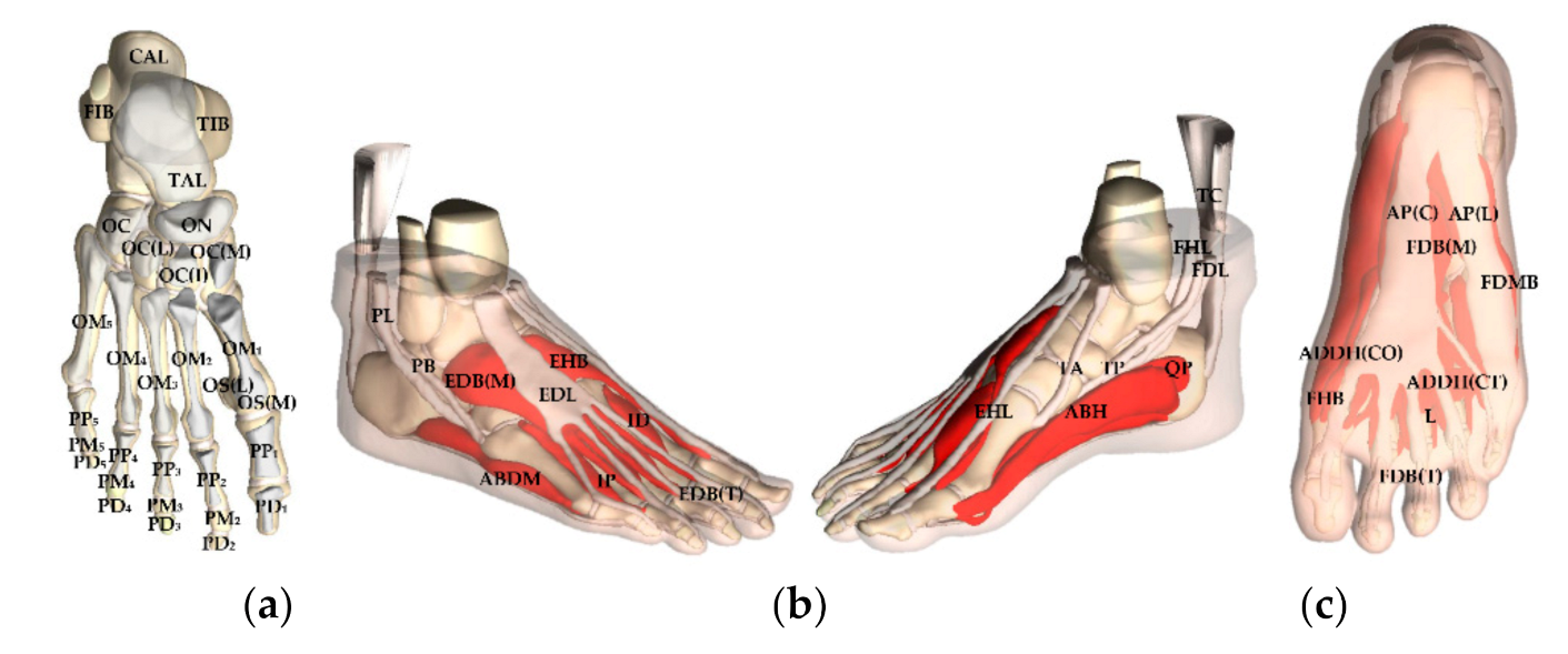
The tissue geometries of the foot and ankle model used in this research were generated through three-dimensional scanning techniques by Morales Orcajo Enrique [
13] of the Applied Mechanics and Bioengineering group (AMB) at the University of Zaragoza, Spain. The foot and ankle model includes cartilage, skin (fat pad), and the cortical and trabecular tissue for bones which comprise 15 phalanges (proximal, medial, and distal), 5 metatarsals, 2 sesamoids (medial and lateral), 3 cuneiforms (medial, intermediate, and lateral), navicular, cuboid, talus, calcaneus, and part of the tibia and fibula (see
Figure 1a). Most muscles and tendons are included with a more realistic three-dimensional morphology. These are the extensor hallucis longus, extensor hallucis brevis, extensor digitorum longus, extensor digitorum brevis, dorsal interossei, plantar interossei, adductor hallucis (transverse and oblique head), abductor hallucis, lumbricals, flexor hallucis brevis, flexor hallucis longus, flexor digitorum longus, flexor digitorum brevis, flexor digiti minimi brevis, peroneus longus, peroneus brevis, tibialis anterior, quadratus plantae, tibialis posterior, aponeurosis plantar (lateral and central), Achilles, and part of the soleus (see
Figure 1b,c). The peroneus tertius and opponens digiti minimi are the only tissues missing from the foot model.
Table 1 shows the abbreviations of the names of each of the tissues that make up the model in
Figure 1.
2.2. Mesh
All the tissues in the foot model were meshed using ICEM® CFD (ANSYS® Inc., Canonsburg, PA, USA). An auto mesh (unstructured) with the octree method was used. First-order tetrahedral elements of variable sizes were used to avoid the loss of morphology and the appearance of singularities in the tissues. An element size of 1 mm was used for small or thin tissues, while for large tissues element sizes of 2 to 4 mm were used.
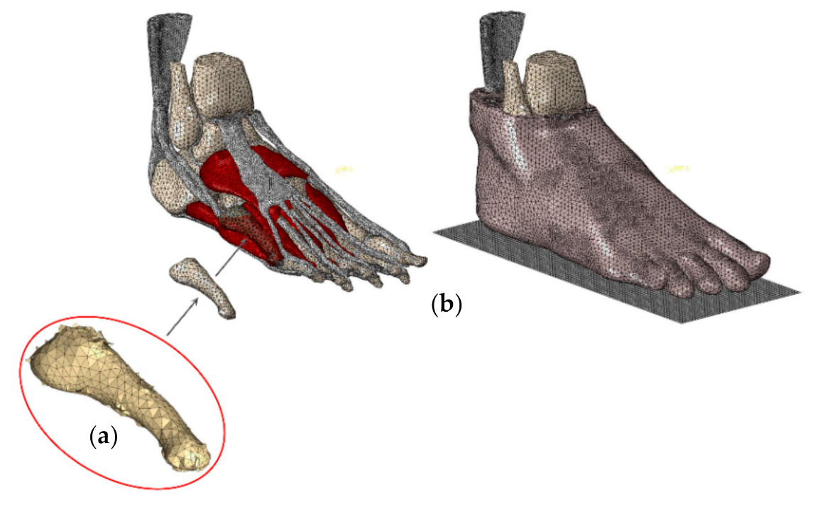
During the meshing stage of the foot model tissues, the software reads the imported files (stereolithography extension) of each of the tissues as a set of points. When the tissues are being meshed, the meshing algorithm cannot identify the boundaries between each tissue. Therefore, the software creates a continuous mesh. Because of that, two problems arose that would have adverse biomechanical effects on the final FEFM response. The first was the generation of undesirable tetrahedral elements at the periphery of the areas in contact between the tissues and the small gaps between them, causing a loss of the model morphology (see
Figure 2a). The second was the shared nodes between mesh elements of the tissues in contact, causing bonded areas that should not be in the model.
Because of these two problems, a reworking of the mesh had to be done for most tissues. In the first stage, which we will call tissue mesh cleaning, those tetrahedral elements of the meshes that were incorrectly assigned were returned to the mesh of the correct tissues. In addition, all those tetrahedral elements of the mesh which modified the morphology of the original tissue were eliminated and, in some cases, new elements were created manually. This mesh reworking of the foot model was done with the same meshing software. The final model was made up of 1,128,602 elements and 208,721 nodes (see
Figure 2b).
In a second stage, which we will call mesh separation between tissues, a separation process of the shared nodes between mesh elements of the tissues was done. During the meshing stage, the software generated a continuous mesh. Continuous mesh generates a sharing of nodes between the mesh elements of the tissues in contact, causing bonded areas. Bonded areas between the FEFM tissues are not physiologically possible because they increase the stiffness of the general response of the foot model, removing the ability of the soft tissues to transfer the load appropriately to the insertion areas on the bone besides erroneously generating the activation of secondary tissues.
The mesh shared between the tissues of the foot model was separated by an algorithm programmed in C++ language in an open-source integrated development environment called Code:Blocks.
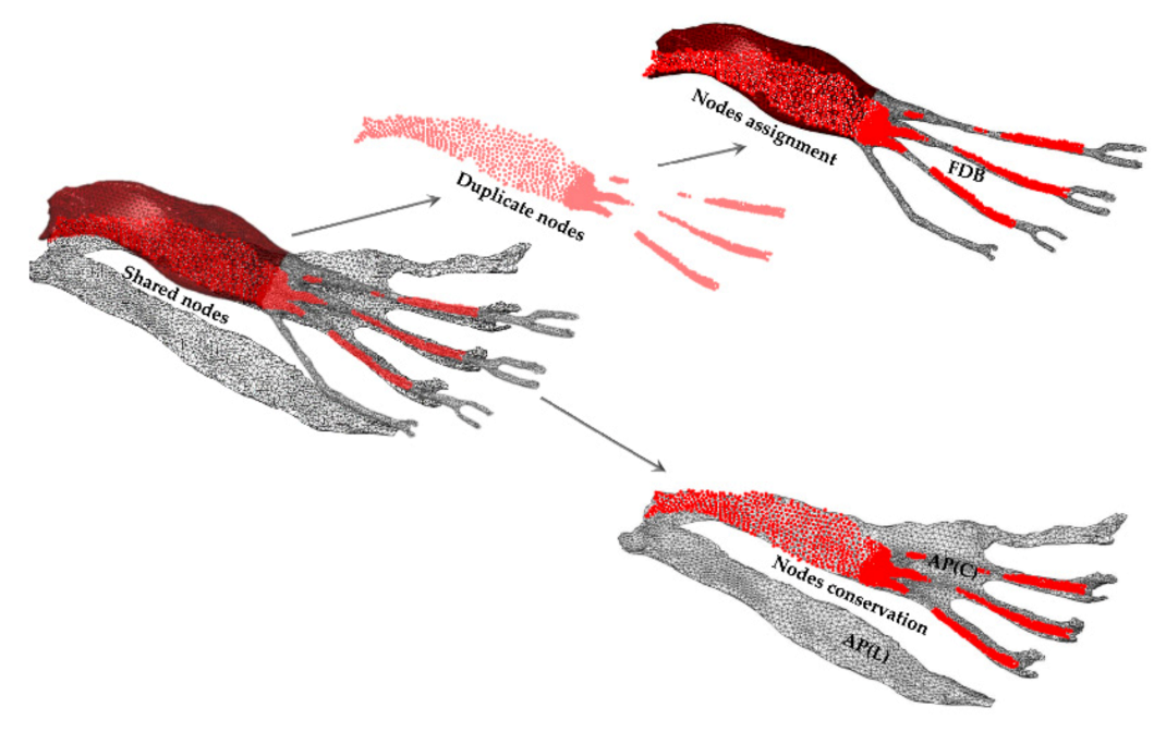
The program created within the integrated development environment is provided with an input file, where there is information on the mesh of the bonded tissues as node groups, node coordinates, and a group of tetrahedral elements with four nodes (C3D4). The algorithm identifies the nodes of the shared faces between tetrahedral elements by the direction of their normal. Once the group of shared nodes has been identified, the program duplicates all the nodes of that group, assigning them the same position as the shared nodes but with a different identification number. The old group of nodes is assigned to one tissue, while the new group of nodes is assigned to the opposite tissue (see
Figure 3). Additionally, the program creates a surface shell with the new nodes between the tissues in contact where the contact between the shell surface and the group of old nodes is subsequently declared. Finally, the program generates an output file with the information of the new nodes, their coordinates, and the three-node triangular shell elements (S3) created. The information contained in the output file is updated in the main file, and in this way, the separation between two meshes is performed.
It is important to mention that no other meshing software, method, or algorithm was used at this stage. Some bonded areas between tissues (such as the bone-fat pad) favored the transmission of loads of the model and avoiding the application of contacts. We only focused on separating those tissues with greater relevance in the analysis.
2.3. Mechanical Properties of Tissues
The mechanical properties used to model the behavior of the foot model tissues in this research were taken from the literature. Cortical bone, trabecular bone, hard cartilage, and soft cartilage were modeled with an isotropic, homogeneous, and linearly elastic mechanical behavior [
14,
15,
16]. For the rest of the tissues, a nonlinear isotropic and homogeneous behavior was used with several hyperelastic deformation energy density functions: fourth-order Ogden function for the lateral plantar aponeurosis, a fifth-order reduced polynomial function for the central plantar aponeurosis [
4], a second-order polynomial function for the skin [
17], and a first-order Ogden function for muscles [
18] and tendons [
19].
2.4. Boundary Conditions and Loads
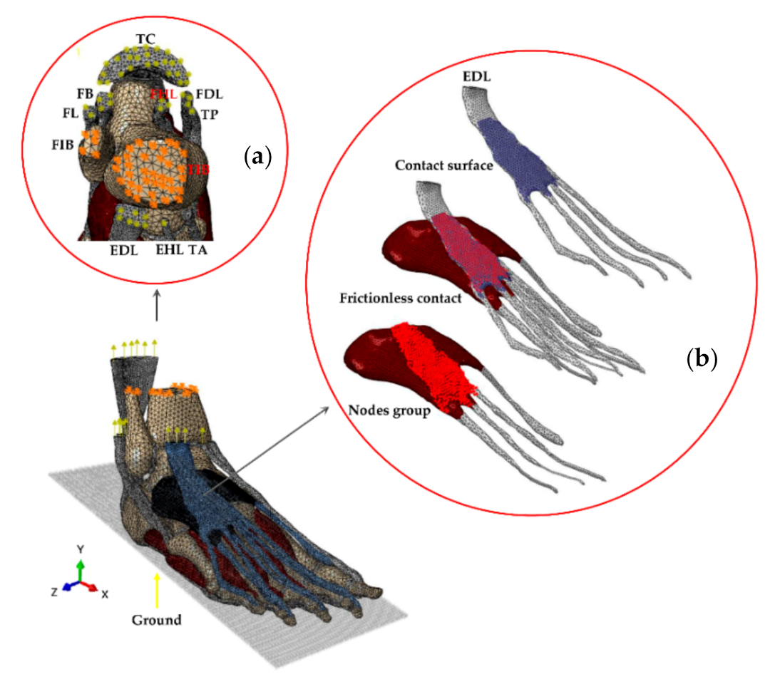
Several boundary conditions were considered to simulate the environment during standing. First, in the three directions, the displacement and rotation were constrained in the tibia and fibula through a set of nodes taken from the upper cross-section (see
Figure 4a). To simulate the support of the foot model against the ground, a flat surface was generated with three-dimensional rigid elements of four nodes (rigid body), allowing only vertical displacement (Y). A force (350 N in the “Y” direction) equivalent to half the subject’s body weight was applied on the flat surface to simulate the reaction force against the ground.
Finally, a series of loads were applied through eight of the main stabilizing tendons activated during the analysis (see
Figure 4a). The magnitudes of these loads were taken from a research paper published by Morales-Orcajo Enrique et al. (2017).
2.5. Contact between Tissues and Ground
Shell surfaces with the shape and extent of the zone of interaction between tissues were created. Later, contacts between the elements whose mesh was separated were applied to avoid penetration and ensure load transfer. Only those sliding contacts between the most relevant tissues of the foot model were generated (see
Figure 4b), that is, in those tissues with greater participation in the transfer of load in the simulation (short extensor-long extensor, short flexor-long flexor, and short flexor-plantar fascia).
Finally, the foot (sole) interaction with the ground was simulated with frictional contact. In this case, a friction coefficient of 0.6 was used [
20].
2.6. Case Studies
Three case studies have been evaluated with the finite element foot model, where we have calculated the contact pressure, displacements, and the maximum principal stress in some tissues to determine the effect that the use of a shared mesh versus a separated mesh can have on these parameters. In addition, we evaluated the biomechanical, convergence, and computational effects of using a shared versus separated mesh and isotropic versus hyperelastic properties in some tissues.
The cases evaluated in this work are detailed below:
Case 1: Model with shared mesh and a linearly elastic, homogeneous, and isotropic mechanical behavior of most of its tissues. For this model, a shared mesh was used (a product of the software), i.e., a mesh with joints (undesired in some cases) between groups of nodes of the tetrahedral elements that make up the mesh of the tissues. The joints presented in this model are in all areas of contact between a tissue and its adjacent tissues. Therefore, a general stiffened FEFM response is expected. Finally, in this simulation, most of the tissues of the model are considered to have an isotropic behavior, except the tendons and skin (hyperelastic behavior).
Case 2: Model with shared mesh and a linearly elastic, homogeneous, and hyperelastic mechanical behavior of most of its tissues. For this model, the same shared mesh is used as for Case 1 is still used. The difference is that in this model, hyperelastic properties are assigned to some tissues (skin, tendons, muscles and the plantar aponeurosis). The purpose of this model is to evaluate the effect on contact pressure when we used hyperplastic instead of isotropic properties.
Case 3: Model with separate mesh and a linearly elastic, homogeneous, and hyperelastic mechanical behavior of most of its tissues. Here the mesh was reworked to undo some joints between muscles, tendons and the plantar aponeurosis.
It is important to understand that some bonded areas between the mesh of the tissues of the foot model are necessary for the transmission of mechanical stimuli between them, as in the case of the musculoskeletal model with the skin (fat) or tendons with some bones. In some cases, applying a contact or a motion constraint instead of leaving the joint generated by the software increase the computation time for convergence. However, some other joints as muscle-to-muscle or muscle-to-bone cause a deficient or abnormal load transmission, thus generating an inaccurate response from the model. Finally, some sliding contacts that were considered important (as short extensor-long extensor, short flexor-long flexor, and short flexor-plantar fascia) were applied in the model to avoid penetration between the tissues and to guarantee an appropriate interaction between them.
2.7. Foot Model Validation
ABAQUS software (ABAQUS Inc., Pawtucket, RI, USA) was used to solve our FEFM. The distribution and magnitude of the contact pressure (plantar pressure) on the sole, specifically under the calcaneus (heel) and the metatarsals heads, reported in previous experimental and numerical analysis were used to compare and validate the numerical foot model developed in this work [
8,
9,
17,
21,
22,
23,
24]. In addition, a study was used of the plantar pressure (footprint) of the patient from which the model was obtained [
19].
Table 2 shows a comparison of the plantar pressure (specifically on the talus and metatarsal heads) of our FEFM with FEFMs, and experimental foot data (EFD) reported by other authors. In this validation stage, the plantar pressure results were taken from those FEFMs whose analyses were performed during standing and under boundary and loading conditions similar to our analysis. Additionally, the table shows in brackets below of our FEFM results (Martínez et al.) the percentage difference between our plantar pressure values and the mean value of the experimental data (ED) and by the finite element method (FEM) reported in the literature by the authors mentioned in the same
Table 2.
3. Results
Plantar pressure, principal stress, and displacements are the comparison parameters that will enable us to quantify the importance of the work done in optimizing the behavior of the tendons and muscles in the foot model.
Table 3 shows the maximum principal stress and the displacement in the three directions for the most relevant tissues in the model without a shared mesh (Case 1) and the model with a separate mesh and sliding contacts (Case 3). In addition, in each column of the sliding foot model, the percentage difference with the values obtained from the model without sliding contacts is shown in brackets.
Table 3 shows that the maximum principal stress obtained on the heel for the non-sliding foot model was −0.1169 MPa, while for the sliding foot model it was −0.1753 MPa. This means an increase of 49.95% for the principal stress in the model with the separated mesh compared to the model with the shared mesh. On the other hand, in the support zone of the metatarsal bones, the maximum principal stress obtained for the non-sliding foot model was −0.0892 MPa, located under the head of the third metatarsal. The maximum principal stress for the sliding foot model was −0.0635 MPa, under the head of the first metatarsal. In this case, the change of the area under greater stress under the metatarsals, as well as the variation of the maximum principal stress of the model with the separate mesh compared to the model with the shared mesh, is attributed to the greater freedom of movement of the tissues resulting from the separation of their bonded areas with the mesh of the tissues in contact. In addition, this greater degree of freedom of movement of the model with the separate mesh can be reflected in the displacements of some tissues (see
Table 3), where there is a tendency towards a greater displacement of up to 458.1% in the model with the separate mesh in comparison with the model with the shared mesh. Moreover, the soft tissue with the greatest variation in the principal stress when considering the condition of mesh separation and slippage, such as aponeurosis plantar (lateral), shows variations of up to 644.6%.
Overall, the soft tissue results showed a mean absolute variation and standard deviation (SD) in stress values of 83.3% (SD 186.9) for the model with the separate mesh (Case 3) compared with the model with the shared mesh (Case 1), while the mean absolute value and standard deviation for the displacements was 17.4% (SD 190.9).
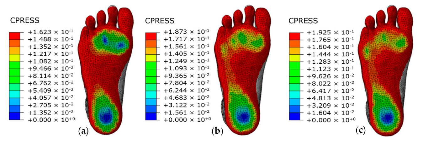
As can be seen in
Figure 5, the distribution of the maximum contact pressure in the three models was on the heel, with a magnitude of 0.162 MPa for the model with the shared mesh and an isotropic behavior of most of its tissues (
Figure 5a) and 0.187 MPa and 0.192 MPa for the models with a hyperelastic behavior of most of its tissues but with a shared mesh (
Figure 5b) and a separated mesh (
Figure 5c), respectively. For the two latter models, we have a percentage variation of the maximum plantar pressure of 2.6% in the model with the separated mesh (Case 3) compared to the model with the shared mesh (Case 2).
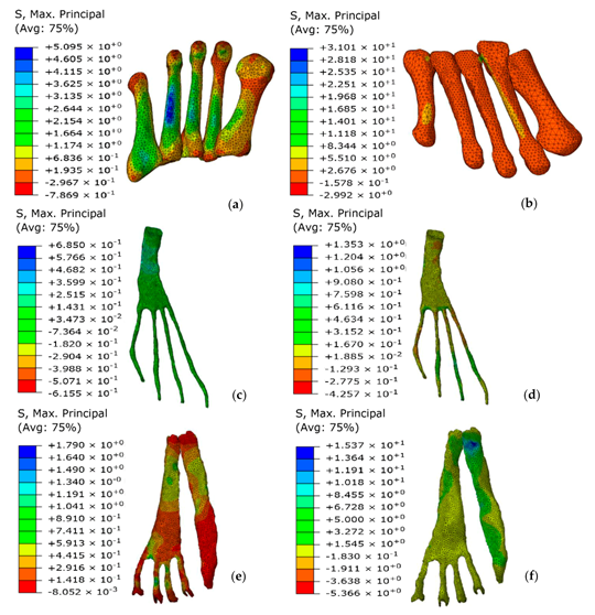
Comparing the maximum principal stress in the metatarsal bones, the maximum stress in the model with the shared mesh and isotropic properties was in the fourth metatarsal bone with a value of 5.095 MPa (see
Figure 6a), while for the model with the separate mesh it was in the second metatarsal bone with a value of 5.510 MPa (see
Figure 6b).
It is important to emphasize the non-homogenous distribution of the maximum principal stress in the extensor digitorum longus and aponeurosis plantar of the model with the shared mesh and isotropic properties when compared with the model with the separated mesh and hyperelastic properties. A better distribution of stress was obtained for the tissues shown in
Figure 6d,f (separate mesh) compared with those shown in
Figure 6c,e (shared mesh) where it was observed a higher stress concentration and singularities. A better distribution of stress is indicative of more appropriate behavior of the tissues by eliminating anchorage areas due to the shared mesh.
4. Discussion
Simulating proper muscle and tendon behavior in a finite element model of a foot is a challenge today. The load transmitted by these tissues to the bone and surrounding tissues can be compromised as early as the meshing stage. During the mesh stage, the software used may or may not generate joints by sharing nodes between mesh elements in all areas in contact between tissues. In both cases, if this fact is overlooked, the behavior of the model may be considerably affected. Before starting the creation of the finite element model, the researcher must define which tissues are necessary, which are relevant, and which others might not be considered in the analysis. The larger the number of elements, the more complicated it becomes to work with the model. In addition, the greater the number of contacts and hyperelastic characterizations of the tissues, the longer the computation time when trying to achieve convergence of the model. In short, the more complete and complex the model, the greater the complexity to obtain a result.
This research shows the structural effect that a shared mesh can have compared to a separate mesh with sliding contacts on the structural behavior of the fabrics of a foot model. For this purpose, one of the most complete finite element foot models available today is used. This model includes almost all muscles and tendons in the foot, with the exception of the peroneus tertius and opponens digiti minimi, which are not necessary for the present analysis. In addition, the muscles, tendons and plantar fascia are modeled with real geometry and simulated with deformable solid elements within the analysis.
According to the values shown in
Table 3, there is a mean absolute increase of 10.6% in the maximum principal stress on the sole for the model with the separate mesh compared with the model with the shared mesh. This increase in stress translates into a better load distribution through the soft tissues. A better stress distribution in the foot model can be observed in a lower number of stress concentrations in different areas of the tissues, as well as in greater freedom of displacement of the tissues. The increased magnitude in displacements may be due to the freedom of movement of muscles, tendons and the aponeurosis plantar resulting from eliminating bonded areas with other tissues. In the tissues of the non-sliding foot model (shared mesh foot model), a greater number of tissues with stress concentrations (singularities) were observed. This translates into a progressive loss of load in these tissues due to the mesh bonding zones of other tissues. This progressive loss of load generates a global stiffness response of the foot model. Strong evidence that soft tissues such as the aponeurosis plantar, peroneus brevis, tibialis posterior and extensor digitorum longus are working better is provided by the values obtained for the mean absolute variation of displacement (17.4%) and stress (83.3%) in the tissues belonging to the model in Case 3 compared to Case 1.
The contact pressure analysis of the models showed that the hyperelastic behavior assigned to muscles of the models corresponding to
Figure 5b,c, compared to the model shown in
Figure 5a with an isotropic behavior of most of its tissues, improved the qualitative distribution of the plantar pressure on the sole, resulting in a more homogeneous pressure. According to the mean of the experimental data taken from the literature [
8,
9,
17,
19,
21,
22,
23,
24], mesh separation in the model in
Figure 5c improved plantar pressure under the heel and metatarsal head by 1.6% and 18.6%, respectively, compared to the model in
Figure 5a. However, the mesh separation between the tissues in the model in
Figure 5c, compared to the shared mesh in the model in
Figure 5b, did not make a considerable difference either quantitatively or qualitatively in the variation of the maximum plantar pressure on the sole. However, there was certainly less stress concentration under the metatarsal head of the third and fourth toes in the model in
Figure 5c compared to the model in
Figure 5b. This is attributed to separating the mesh of the long extensor tendons with adjacent tissues, allowing a large part of the load on these tissues to reach the insertion in the distal phalanges, generating a slight elevation of the forefoot.
As can be seen in the tissues in
Figure 6d,f (where their mesh was separated) compared to the tissues in
Figure 6c,e (with the shared continuous mesh), there is a better distribution of the maximum principal stresses (fewer singularities), which is indicative of a more adequate behavior of these muscles in the foot model.
The results obtained in the model presented in this work, where the mesh among bones, muscles, tendons and plantar fascia was separated, showed a significant improvement in the general behavior of the model. It is, therefore, imperative that in this type of model used for the analysis of biomechanical phenomena, the soft tissues should be separate from their surrounding tissues, especially in those analyses focused on the structural behavior of muscles, tendons and the plantar fascia.
When creating a model made up of 101 elements (tissues), it is to be expected to find a high degree of interaction between the tissues. In total, 138 bonded areas were counted in the foot model. Some of the tissues had more than four bonds. Analyzing the behavior of the case studies, specifically where it was observed that the separation of the mesh does not have a considerable effect on the variation of plantar pressure. Furthermore, in some cases, when separating the mesh between two bonded tissues, it was necessary to apply a contact, and in turn, the contact considerably increased the calculation time. The decision was made to separate only those bonded areas that were relevant to the analysis. Given that skin is a tissue that covers the entire musculoskeletal model, its mesh generates joints with bone, tendons, muscles and the plantar aponeurosis. Despite considering the skin as a hyperelastic tissue, the junction with the tendons causes a loss of load. However, it is difficult to generate an internal contact of the skin with the musculoskeletal model so that the latter transmits the mechanical stimuli more adequately to the adipose tissue. For this reason, one of the important limitations in our analysis is the loss of load that the skin causes on the active tendons in the stance phase due to the shared mesh between them.
Finally, as a result of the analysis, we can suggest for future work that for foot models which include muscles, tendons, the plantar fascia and ligaments simulated with solid deformable elements, it is advisable to use a separated mesh in tissues such as bone (cortical bone) and skin (fat pad). Furthermore, and subsequently, we use specialized meshing software to generate the joints or separations between the mesh elements where later a contact condition or motion constraints will be applied that will help to better transmit the effects from one mesh to another. In this way, it will be possible to obtain a better behavior of the tissues in the model.
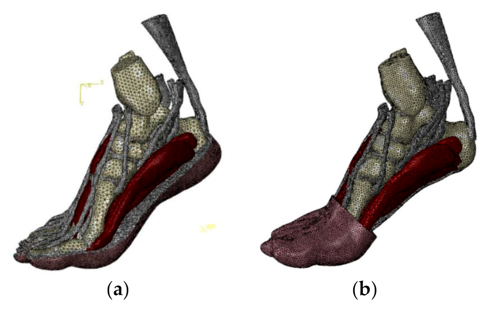
The use of a shared or separate mesh of the skin with the musculoskeletal tissue makes it very difficult to adequately simulate the behavior of the rest of the soft tissues. Therefore, depending on the case study, it could be advisable to generate simplified models where a separated mesh and only some tissues or a portion of them could be used, as shown in
Figure 7.
5. Conclusions
The results obtained in this work showed that a more appropriate mechanical characterization of tissues such as muscles, tendons, plantar aponeurosis and skin (fat-pad) improved the quantitative and qualitative distribution of plantar pressure. What is referenced in the text above, can be seen by comparing the results between
Figure 5a,c. Contrary to expectations, the mesh separation work performed did not have a significant impact on plantar pressure. The above can be corroborated by comparing the model results in
Figure 5b with
Figure 5c.
However, the work of mesh separation between the tissues of most relevance for analysis (plantar aponeurosis and extrinsic musculature) showed an improvement in the structural behavior of the individual tissues. Quantitatively in the data shown in
Table 3, displacement differences of up to 458.1% can be found. Qualitatively we can see in
Figure 6b,d,f (Case 3) a low concentration of the maximum principal stress on the tissues compared with the tissues in
Figure 6a,c,e (Case 1). The result is a better structural behavior of the tissues and better load transmission to the areas where they are inserted into the bone. The improvement made in the model can lead to a better simulation of specific tissues when a specific pathology is analyzed.
The work carried out in this paper generated knowledge on how the use of a separate mesh with contacts and hyperelastic properties improves the structural behavior of the tissues and the model in general, compared to the use of a shared mesh with isotropic properties. In addition, it could be proven that the use of a very detailed finite element model generates more computational time in the solution, requires equipment with greater capacity to solve the system of equations, increases the level of difficulty in finding convergence, and increases the complexity of simulating each of the tissues appropriately.
Therefore, it is recommended to take into consideration, whenever possible, the creation of simplified models to avoid or reduce some of the problems mentioned in the research. A simplified model could have a good approximation of the case study, but without having to face the problems that working with a more detailed model could bring.


 ,
, 


