1. Introduction
Digital holographic interferometry (DHI) and electronic speckle pattern interferometry (ESPI) in the long-wave infrared (LWIR) spectral range have been used recently for different applications, through the combination of CO
2 lasers with thermal imaging devices for recording numerically digital holograms or specklegrams [
1,
2]. The latter are compared numerically, giving rise to interference patterns, the so-called interferograms, from which surface displacements can be deduced. The distance between fringes in such interferograms is proportional to the wavelength used. With LWIR wavelengths 20 times larger than visible ones, LWIR DHI yields to deformations/displacements 20 larger than in visible DHI. Also, it is well known that stability requirements of holographic experiments must be typically of one tenth of the wavelength during hologram/specklegram recording. At such long wavelengths, the stability requirements are then also decreased by a factor of 20 compared to visible wavelengths. We already have presented various developments concerning nondestructive testing by LWIR speckle interferometry [
2,
3,
4,
5,
6], vibration analysis [
7] and deformations metrology of space structures by LWIR DHI [
8,
9,
10,
11].
In this keynote paper, we review the latter, from the initial investigations for measuring large deformation of aspheric reflectors, to the testing of a mosaic of detectors, consisting of rigid body motions and deformations. Recent results obtained in the last measurement campaign will be presented.
2. Long-Wave Infrared Digital Holography Technique for Large Space Aspheric Reflector Testing
LWIR digital holography has been developed in the frame of an European Space Agency project for monitoring the deformations of large space reflectors with various shapes (parabolas, ellipses…) which undergo thermal cycling tests [
8]. The size of reflectors ranged between 1 and 4 m with thermo-elastic deformations between 1 and 250 µm. Classical interferometry is generally applied for measuring the surface shape of such reflectors but it requires null-lenses for illuminating the test part and limiting wavefront differences with respect to the reference beam. Such expensive (custom-made) null-lenses must be carefully aligned to avoid generating artificial wavefront errors. In that respect a holographic technique will circumvent the need of costly external components because it measures changes in the surface shape. Holography allows then the use of inexpensive components off the shelf (COTS) elements. The interferometric DH configuration used here is an in-line Fresnel DH [
12] with phase-shifting [
13,
14]. We use an in-line DH configuration because it allows a higher resolution than the off-axis configuration. However, we need to use phase-shifting for suppressing unwanted overlapping reconstruction orders. Temporal phase-shifting usually limits the use of DH to slow phenomena but this is not a critical issue here since the thermal variations provoked on the specimen are very slow ones.
One constraint of LWIR is that objects reflect specularly unless their surface roughness is similar or larger than the wavelength. For space specimens a scattering coating cannot be applied on the surface. Therefore, we had two choices: (1) illuminate the test object in a pure specular scheme and collect the beams prior to recombine them with the reference or (2) illuminate it through diffuser [
9]. In the case of strong aspheres, the first configuration requires large costly ZnSe lenses. One advantage of DH is that complex optical elements are not needed for imaging an object. Therefore, illuminating the test article through an adapted diffuser has been considered. The advantage of LWIR DH is that the size of the reconstructed object is larger than the ones in the visible. The object reconstructed size
L can be calculated [
2,
8] knowing the wavelength
λ, the pixel pitch
Δ and the object distance to sensor
D and is expressed as
L = λ D/2Δ. Taking into account the wavelength and the state-of-art pitch of sensors, the
λ/
Δ in visible DH is on the order of 0.05 while it is typically 5 times larger in LWIR, allowing reconstruction of larger objects with LWIR DH.
For these reasons a LWIR DH set-up with illumination of test object through diffuser was the best configuration to develop. Since the system must be used with test object in vacuum, the laser and camera had to be placed out of the vacuum chamber with ZnSe windows in the laser beam and image paths.
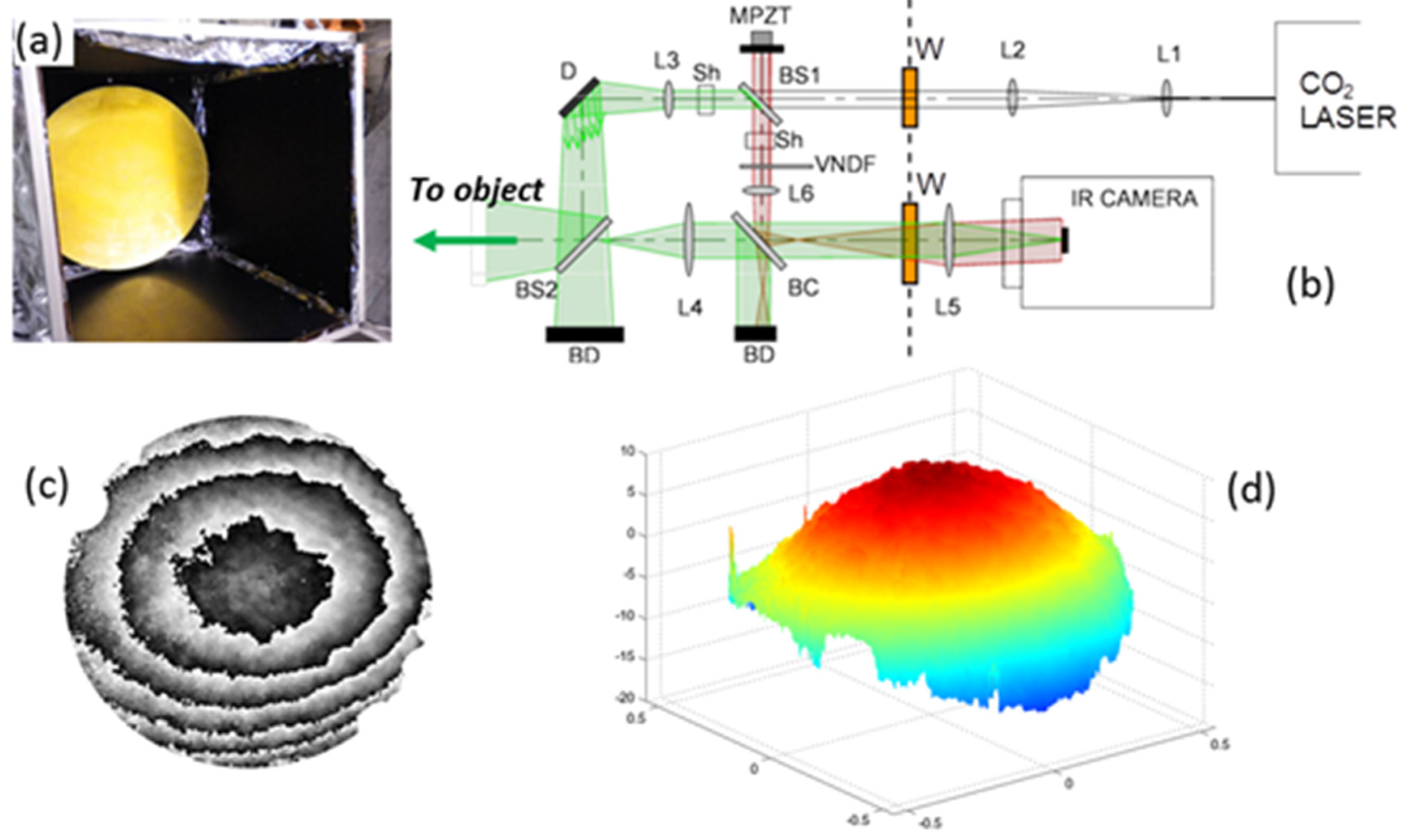
Figure 1b shows a sketch of the set-up, except the test reflector which is on the left hand side of the second beamsplitter (BS2).
The tested reflector is shown in
Figure 1a, inside a thermal shroud, placed in a vacuum chamber. It is a parabolic shaped reflector of 1.1 m diameter with a focal length of 1.58 m. Its structure is made of carbon fibre reinforced polymer, with a gold coating on the optical surface.
Figure 1b shows the rest of the set-up. The laser and the camera are not vacuum compatible. Therefore, they are placed outside the vacuum chamber. The main part of the interferometer is inside the chamber, and beams pass through ZnSe windows (W). The dashed line represents the limit of the vacuum. The light coming from the laser is expanded (L1–L2) and is split in the reference arm and object arm. The object beam reaches a diffuser D (a thick metal plate with scattering coating) which illuminates the object through BS2. The light is reflected by the object towards the camera and is recombined with the reference beam through the beam combiner (BC). An afocal system (L4–L5) is used for placing the image plane out of the vacuum chamber. In the reference beam an afocal system enlarges the beam for covering the entire sensor (L6 combined with L5 of the object beam afocal system). Sh represent a shutter, BD beam dumps, VNDF a variable neutral density filter for decreasing the reference beam intensity. MPZT is the reference mirror mounted on piezotranslator.
Figure 1c,d show a typical result obtained during a thermal-vacuum test: (
c) is the phase difference calculated between two instants (temperature variation between 224 K and 107.5 K); (
d) is the final deformation after phase unwrapping and 3D plot.
3. Cryogenic Testing of Segmented Space Detector
The object to be tested is focal plane array (FPA) of the Near Infrared Spectrometer and Photometer (NISP) of the EUCLID space mission. It was provided by the Laboratoire d’Astrophysique de Marseille (LAM). The specimen consists of 4 × 4 mosaic of array detectors, some of which are representative of those finally used in the flight model. They are assembled on a structures and it was required to measure the global deformation of the ensemble, the deformation of each detector as well as the displacement of each of them with respect to their neighbors. The range of deformation was 20 µm which is compatible with LWIR DHI and explains the choice of this technique for the measurement. Also since relative piston movements between sub-assemblies are seeked, we incorporated the temporal phase unwrapping [
15] to the basic technique reported above. A first model of FPA has been tested in a previous campaign and already reported. More recently, changes have been made on the FPA and a new test needed to be performed on the same basis. We report here the new testing.
Figure 2a shows a sketch of the 4 × 4 mosaic of detectors and the surrounding assembly.
Figure 2b shows the type of representative detectors used. STM are simply piece of bare silicon, FM are true flight model detectors and MUX are similar to FM but without the sensitive layer. The ensemble of detector has a dimension of 17 × 17 cm
2.
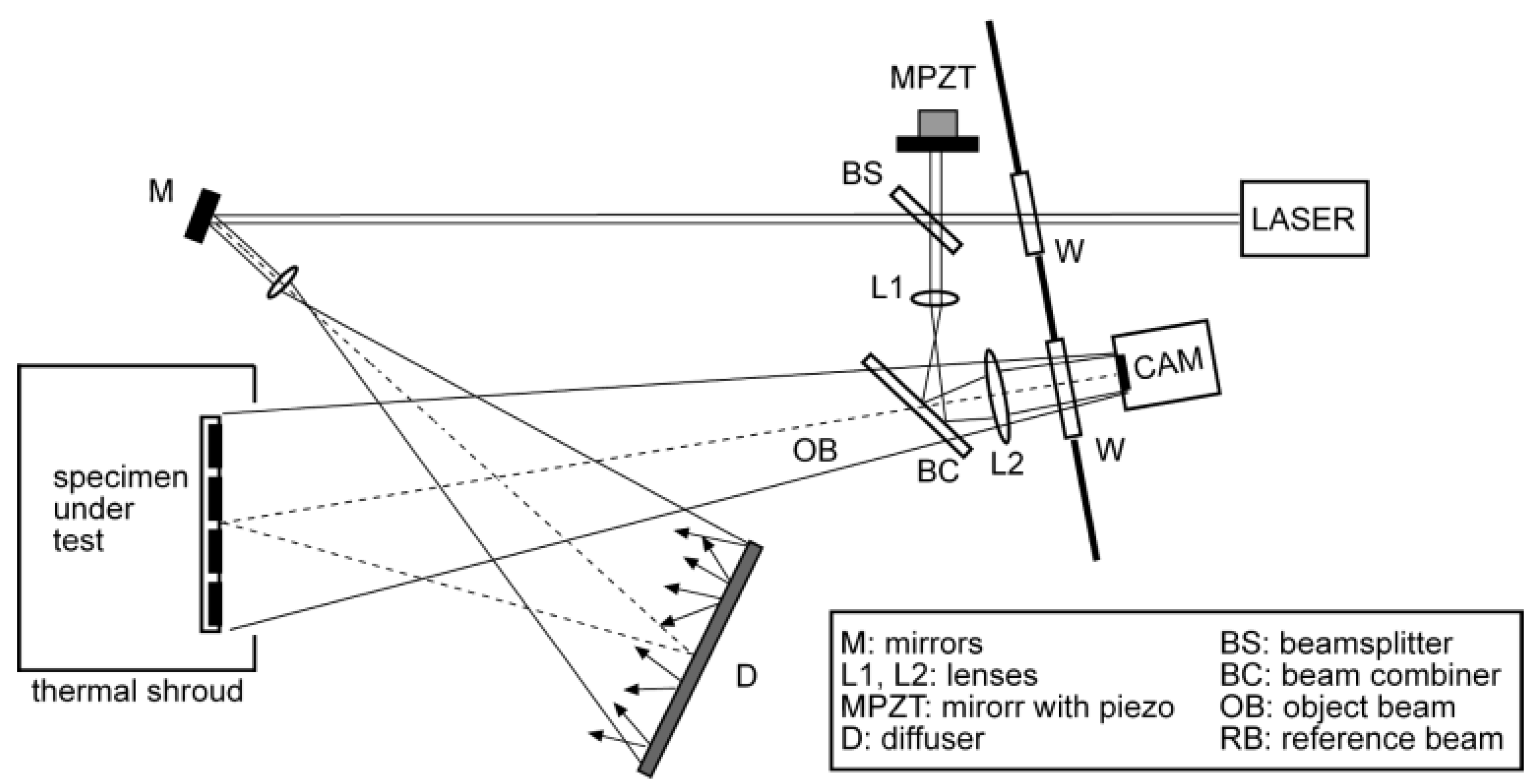
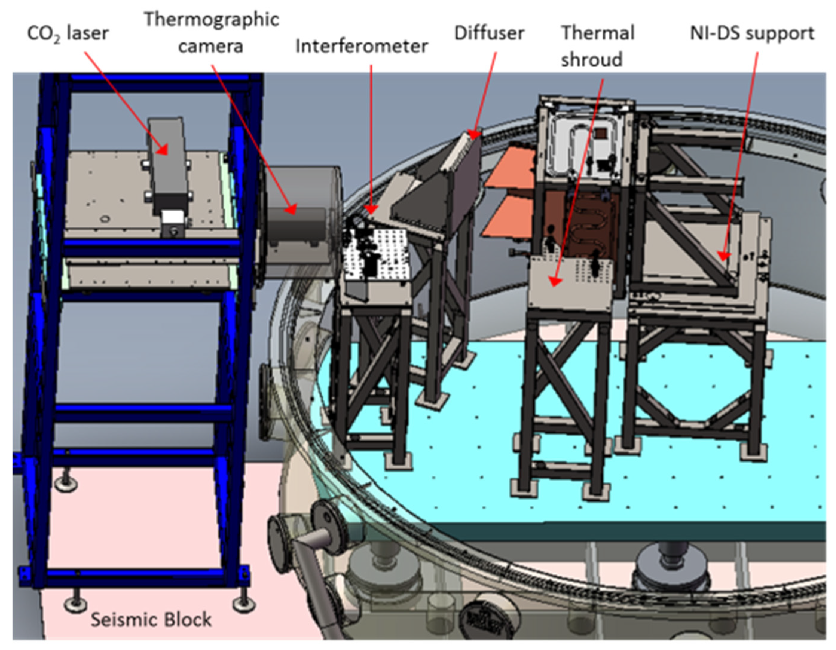
Figure 3 shows a sketch of the DH setup and
Figure 4 shows a CAD drawing of the ensemble of the test bench with the vacuum chamber located on the right. On the left is a tower with elements located out of the vacuum chamber (the microbolometer camera and laser) and which are not vacuum compatible. The specimen is surrounded by a thermal shroud insuring temperature change by radiative transfer. The interferometric setup is the one of an in-line Fresnel DH associated with phase-shifting, similar to the one already presented earlier. Since objects are more specular in LWIR than in visible and especially the specimen is made of polished materials, we make use of a diffuser illumination (D) which was considered in previous experiments. The results obtained in the first campaign have been presented in details elsewhere [
11].
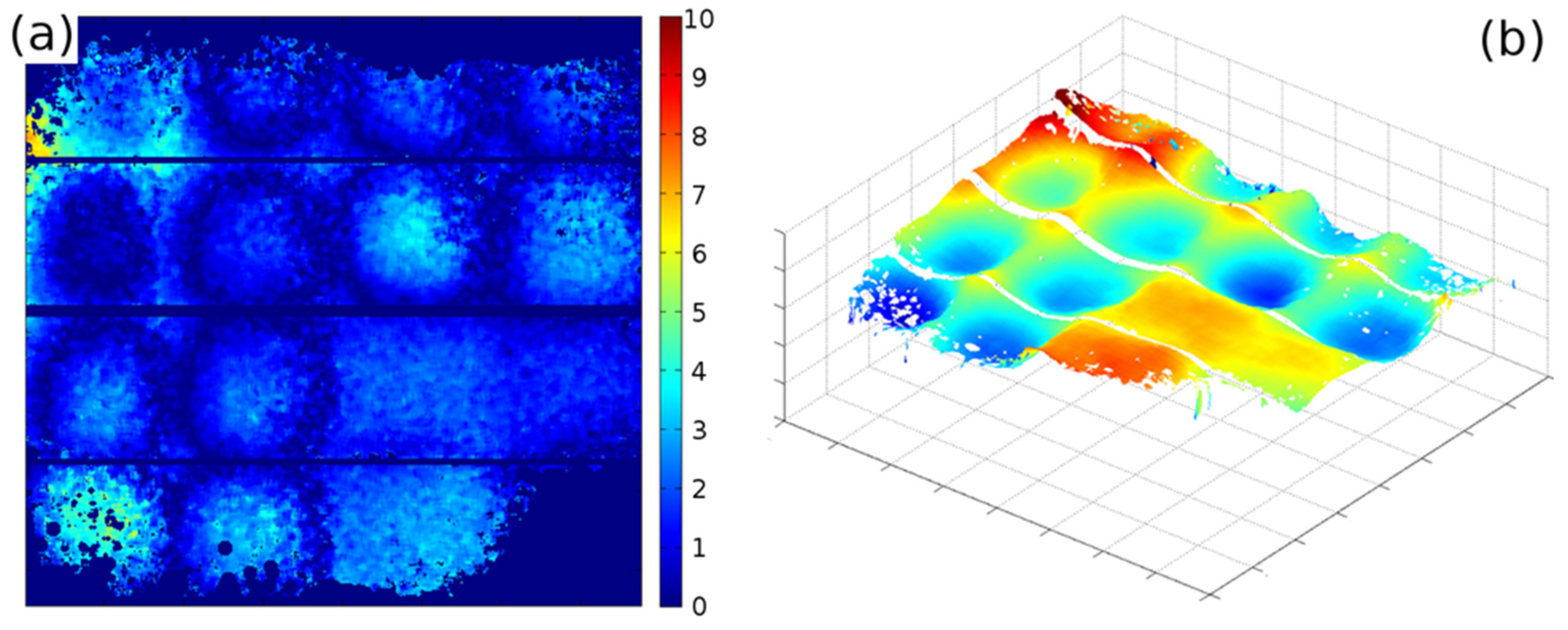
Figure 5 shows the deformation of the detectors between 293 K and 90 K.
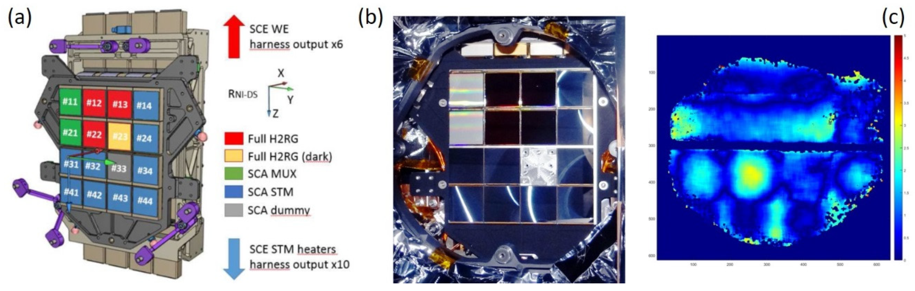
More recently, a similar measurement campaign has been performed with the same set-up and experimental conditions. However, a modified mosaic of detectors was proposed for testing, as a result of design and material modification by the LAM.
Figure 6a shows the new configuration of detectors, with some similarities compared to the previous specimen.
Figure 6b is a picture of the object taken prior to testing.
Figure 6c shows the final deformation of the detectors. Here, we can see that the external part of the specimen is masked out. These points were automatically rejected because of the noise in the measurement, overpassing a specified level. However, the number of measurable detectors is sufficient due to redundancy for most of them.
4. Discussion-Conclusions
LWIR digital holography allows capturing hologram of large objects in industrial environment. The long wavelength has the advantage of decreasing the stability constraints generally required in interferometric set-up. Moreover, the long laser wavelength (here 10 µm) allows to perform large deformation measurements. Such deformations are typical of large space structures undergoing important temperature variations which are typical to the one present when such payloads are on orbit. We have applied this technique in two examples of interest. The first one is a large aspheric reflector of 1.1 m diameter, the second one a mosaic of 4 × 4 detectors of 17 cm × 17 cm. For the second one, the tracking of the phase on each of the detectors has been performed, through acquisition of a large number of holograms during typically 48 h and application of the temporal phase unwrapping method.
This paper demonstrates that LWIR digital holographic metrology has become a mature technology which can be applied outside laboratories. It is capable to cope with demanding applications like measuring large displacements of complex objects undergoing large temperature variations in difficult working environments.
Author Contributions
M.G. performed wrote the paper and is the group leader, C.T. was the project manager of both projects, J.-F.V., F.L. and C.T. participated to the different campaigns, developed the hardware and processed the data.
Acknowledgments
The first results on the parabolic reflector have been obtained with financial support of the European Space Agency (GSTP program, contract No. 22540/09/NL/SFe). The results on the detectors mosaic have been carried out under financial support of PRODEX program and with the fruitful collaboration of the Laboratoire d’Astrophysique de Marseille.
References
- Georges, M.P. Long-wave infrared digital holography. In New Techniques in Digital Holography; Picart, P., Ed.; Wiley: Hoboken, NJ, USA, 2015; pp. 219–254. [Google Scholar]
- Vandenrijt, J.-F.; Georges, M.P. Electronic Speckle Pattern Interferometry and Digital Holographic Interferometry with Microbolometers Arrays at 10.6 Microns. Appl. Opt. 2010, 49, 5067–5075. [Google Scholar] [CrossRef] [PubMed]
- Alexeenko, I.; Vandenrijt, J.-F.; Pedrini, G.; Thizy, C.; Vollheim, B.; Osten, W.; Georges, M.P. Nondestructive testing by using long wave infrared interferometric techniques with CO2 lasers and microbolometer arrays. Appl. Opt. 2013, 52, A56–A67. [Google Scholar] [CrossRef] [PubMed]
- Vandenrijt, J.-F.; Thizy, C.; Alexeenko, I.; Pedrini, G.; Rochet, J.; Vollheim, B.; Jorge, I.; Venegas, P.; López, I.; Osten, W.; et al. Mobile speckle interferometer in the long-wave infrared for aeronautical nondestructive testing in field conditions. Opt. Eng. 2013, 52, 101903. [Google Scholar] [CrossRef]
- Georges, M.P.; Vandenrijt, J.-F.; Thizy, C.; Alexeenko, I.; Pedrini, G.; Vollheim, B.; Lopez, I.; Jorge, I.; Rochet, J.; Osten, W. Combined holography and thermography in a single sensor through image-plane holography at thermal infrared wavelengths. Opt. Exp. 2014, 22, 25517–25529. [Google Scholar] [CrossRef] [PubMed]
- Georges, M.P. Speckle interferometry in the long-wave infrared for combining holography and thermography in a single sensor: Applications to nondestructive testing: The FANTOM Project. In Proceedings of the SPIE 9525, of Conference Optical Measurement Systems for Industrial Inspection IX, Munich, Germany, 22 June 2015; 95251L. SPIE: Bellingham, WA, USA. [Google Scholar] [CrossRef]
- Languy, F.; Vandenrijt, J.-F.; Thizy, C.; Rochet, J.; Loffet, C.; Simon, D.; Georges, M. Vibration mode shapes visualization in industrial environment by real-time time-averaged phase-stepped ESPI at 10.6 µm and shearography at 532 nm. Opt. Eng. 2016, 55, 121704. [Google Scholar] [CrossRef]
- Georges, M.P.; Vandenrijt, J.-F.; Thizy, C.; Stockman, Y.; Queeckers, P.; Dubois, F.; Doyle, D. Digital holographic interferometry with CO2 lasers and diffuse illumination applied to large space reflectors metrology. Appl. Opt. 2013, 52, A102–A116. [Google Scholar] [CrossRef]
- Vandenrijt, J.-F.; Thizy, C.; Queeckers, P.; Dubois, F.; Doyle, D.; Georges, M. Long-wave infrared digital holographic interferometry with diffuser or point source illuminations for measuring deformations of aspheric mirrors. Opt. Eng. 2014, 53, 112309. [Google Scholar] [CrossRef]
- Georges, M.P.; Vandenrijt, J.-F.; Thizy, C.; Stockman, Y.; Queeckers, P.; Dubois, F.; Doyle, D. Digital Holographic Interferometry with CO2 Laser Applied to Aspheric Space Reflector Testing. In Proceedings of the Digital Holography and Three-Dimensional Imaging, Kohala Coast, HI, USA, 21–25 April 2013. OSA Technical Digest (online) (Optical Society of America, 2013); paper DW3A.4. [Google Scholar]
- Vandenrijt, J.-F.; Thizy, C.; Martin, L.; Beaumont, F.; Garcia, J.; Fabron, C.; Prieto, E.; Maciaszek, T.; Georges, M.P. Digital holographic interferometry in the long-wave infrared and temporal phase unwrapping for measuring large deformations and rigid body motions of segmented space detector in cryogenic test. Opt. Eng. 2016, 55, 121723. [Google Scholar] [CrossRef]
- Picart, P.; Leval, J. General theoretical formulation of image formation in digital Fresnel holography. J. Opt. Soc. Am. A 2008, 25, 1744–1761. [Google Scholar] [CrossRef] [PubMed]
- Yamaguchi, I.; Zhang, T. Phase-shifting digital holography. Opt. Lett. 1997, 22, 1268–1270. [Google Scholar] [CrossRef] [PubMed]
- De Nicola, S.; Ferraro, P.; Finizio, A.; Pierattini, G. Wave front reconstruction of Fresnel off-axis holograms with compensation of aberrations by means of phase-shifting digital holography. Opt. Las. Eng. 2002, 37, 331–340. [Google Scholar] [CrossRef]
- Huntley, J.M.; Saldner, H.O. Temporal phase-unwrapping algorithm for automated interferogram analysis. Appl. Opt. 1993, 32, 3047–3052. [Google Scholar] [CrossRef] [PubMed]
| Publisher’s Note: MDPI stays neutral with regard to jurisdictional claims in published maps and institutional affiliations. |
© 2018 by the authors. Licensee MDPI, Basel, Switzerland. This article is an open access article distributed under the terms and conditions of the Creative Commons Attribution (CC BY) license (https://creativecommons.org/licenses/by/4.0/).


