Design and Calibration of a 6-Component Balance on a Bicycle Steer †


Department of Electro Mechanics, KU Leuven, 9000 Leuven, Belgium
*
Author to whom correspondence should be addressed.
†
Presented at the 18th International Conference on Experimental Mechanics (ICEM18), Brussels, Belgium, 1–5 July 2018.
Proceedings 2018, 2(8), 520; https://doi.org/10.3390/ICEM18-05414
Published: 29 June 2018
(This article belongs to the Proceedings of The 18th International Conference on Experimental Mechanics)
Abstract
:The present article describes the methodology used to design and calibrate a 6-component balance. This balance is utilized in an instrumented bike measuring the forces applied on the handlebars. This instrumentation bike maps all riders induced loads. In the designing process, Finite Element Analysis was used. Calibrating the balance was done using the Least Square Regression Method which allows combining multiple loads during calibration and thus requires less samples. The balance operates with a maximum full scale error of 0.53%.
1. Introduction
In 2014 there were 200 million electrical bicycles worldwide and with a gradually increasing annual sale, an electrical bicycle is a widely used vehicle ([1] p. 62). The majority of electrical bike users are older or less fit and therefore more vulnerable to injuries caused by long-term maladaptive cycling posture. Nowadays, bike fitters are adjusting electrical bicycles exactly the same as manual bicycles while applied loads are different and electrical bikes posture is generally more relaxed. Mapping these cycling differences and composing fitting rules for electrical bikes requires an instrumented bike measuring the loads applied on the saddle, steer and pedals.
This instrumented bike can also be used to check the progress in injured cyclists and adapt their revalidation accordingly. With a sufficient amount of gathered data a standard load profile on every contact point can be composed and used in fatigue testing to optimize bicycle components.
The steer balance is a 6-component load cell replacing the stem while connecting the steer with the fork.
2. Instrumentation Bike
To measure the complete interaction between the cyclist and the bicycle all contact points are provided with a balance. In recreational cycling all the limbs as well as the bottom provide a contact point. Those contact points are situated on the handlebars, the pedals and the seat. While the pedals are equipped with separate balances, the loads on the handlebars balance are measured together through a balance located in the stem. To simplify the pedal balances, a 3-component balance was designed. Since no clipless pedals will be used on this bike the moments are neglected and only the forces are measured. Combined with an Internal Measurement Unit (IMU) on both pedals and an encoder on the bottom, bracket effective power can be obtained. To check the stability of the bicycle an IMU measures the bikes frame orientation and an encoder the steering angle. The instrumentation is mounted on the bicycle like normal bicycle parts and with minor modifications, it can be utilized on different models.
3. Design
3.1. Balance Requirements
The balance must endure applied loads. However, due to the limited research done on bicycle loads not much information exists on the complete stem load and consequently on the balance load requirements. According to Jean-Marc Drouet et al. who equipped a racing bicycle with a 3 component balance maximum loads are 790 N transversal and 135 Nm sagittal during road impact. Table 1 shows impact loads and periodically applied loads during uphill climbing out of the saddle [2].
To design a low-cost 6-component balance adapting steer parts was considered first. Attaching strain gauge pairs on the handlebar tube in different configurations measures certain loads [2,3,4]. This however would only measure loads applied on one side of the steer or requires the same configuration on the other side of the steer. Attaching the strain gauges onto the stem would only require each configuration one time [2]. The fabrication of the 6-component balance for the saddle which is a seat post with added strain gauges concluded that the axial force couldn’t be properly measured and required adding an extra part measuring the axial force. Another possibility is designing a stem with an incorporated balance. For an optimal accuracy the balance needs a maximum signal during its respective load and minimal signal during other loads. This is achieved with a structure designed to cause maximum deformation in strain gauges while other strain gauges are on the neutral axis. The balance is composed of 3 flexural components each measuring one load and its corresponding moment. The components are orientated according to orthogonal axis for each directional load. For simplification and to decrease the production cost, the flexural elements are identical.
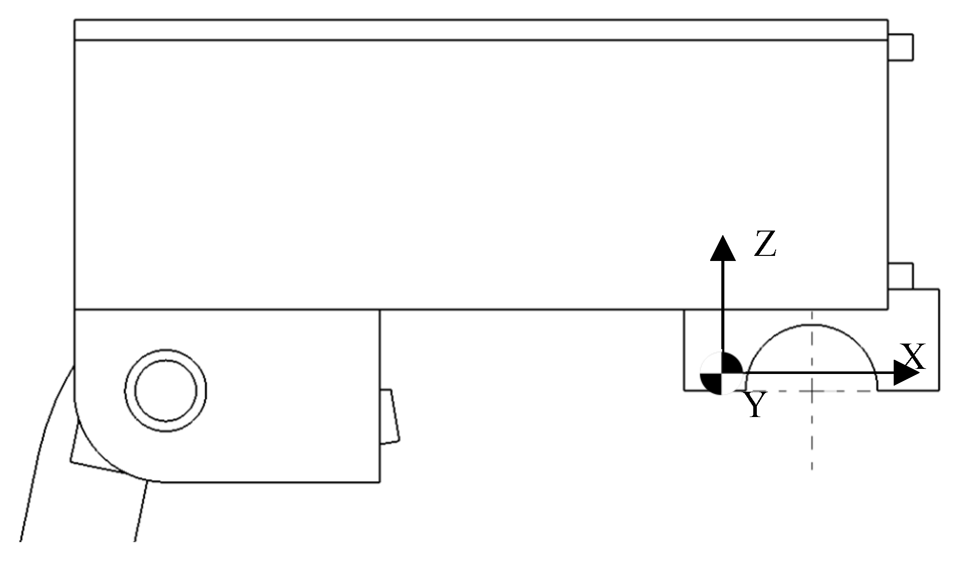
The balance replaces the stem and connects the fork with the handlebars. The connection to the fork is identical to the stem. The stem is attached with the fork through a clamped tube able to change height and connects with the steer by a bracket. Both connections are able to change the position of the steer and can be mounted on the majority of other bicycles. In the centre of the bracket is the origin of the applied loads as seen in Figure 1. These connections are both cylindrical and have the standard bicycle diameters, so the balance can be equipped on different bicycles without adjustments.
3.2. Load Cell Element
The element has three parallel beams with gauges attached on the outer ones. This flexural element is similar to elements utilised in balances for wind/water tunnel tests where high accuracy is required [5]. Figure 2 shows the element with the full Wheatstone bridge strain gauge configurations.
The flexural elements are designed for a maximum tension or compression caused by the exerted force. The force causes the upper strain gauge to extend while raising the resistance and the lower ones to compress, lowering the resistance.
This change is measured with the Wheatstone bridge as in Formula 1
The change in resistance is proportional to the distance from the applied force. The strain gauges of the force measurement are on each side attached on a fixed distance from each other, to cancel out the moment, only measuring the force independently of the point of attachment.
Using FEA for iterative design, the dimensions of the elements are gathered able to withstand maximum applied loads. The loads from Table 1 occurred on a racing bicycle whereas the balance will be used on a recreational bicycle with suspension. Consequently, loads will not surpass impact loads and the balance solidity doesn’t need to suffice above mentioned loads. A downward force of 790 N was applied 170 mm from the element in FEA to simulate impact loads.
The final element simulation on Figure 3 shows a maximum von Mises stress of 1.8 × 10⁸ N/mm2 which is below the yield strength of mild steel of 2.2 × 10⁸ N/mm2 staying within the elastic zone of the material.
4. Calibration
With a perfectly produced balance, each load component change results in a single output alteration. Due to minor imperfections in manufacturing, material property variation and strain gauge placements, this is never the case and load components cause minor changes in every output signal. To cancel out this cross-sensitivity and convert the measurements to relevant values, the measurements are converted using a calibration matrix. This calibration matrix is calculated with the least square Global Regression Method. Compared to traditional calibration methods which are restricted to single- or two-component loads GRM allows applying multiple loads simultaneously during calibration. GRM obtains similar accuracy as traditional calibration methods with a significantly lower number of calibration loads. This calibration can easily be handled manually with a suitable amount of work. With GRM the applied calibration loads can be in the actual loading range, increasing the balance accuracy [6].
Measured signals are converted to comprehensible load values using a first order calibration as shown in Formula 2
where Y is a n × 6 matrix of loads, C the 6 × 6 calibration matrix and X the n × 6 matrix of the acquired signals with n the number of samples. To calculate the calibration matrix Formula 2 is transformed to Formula 3
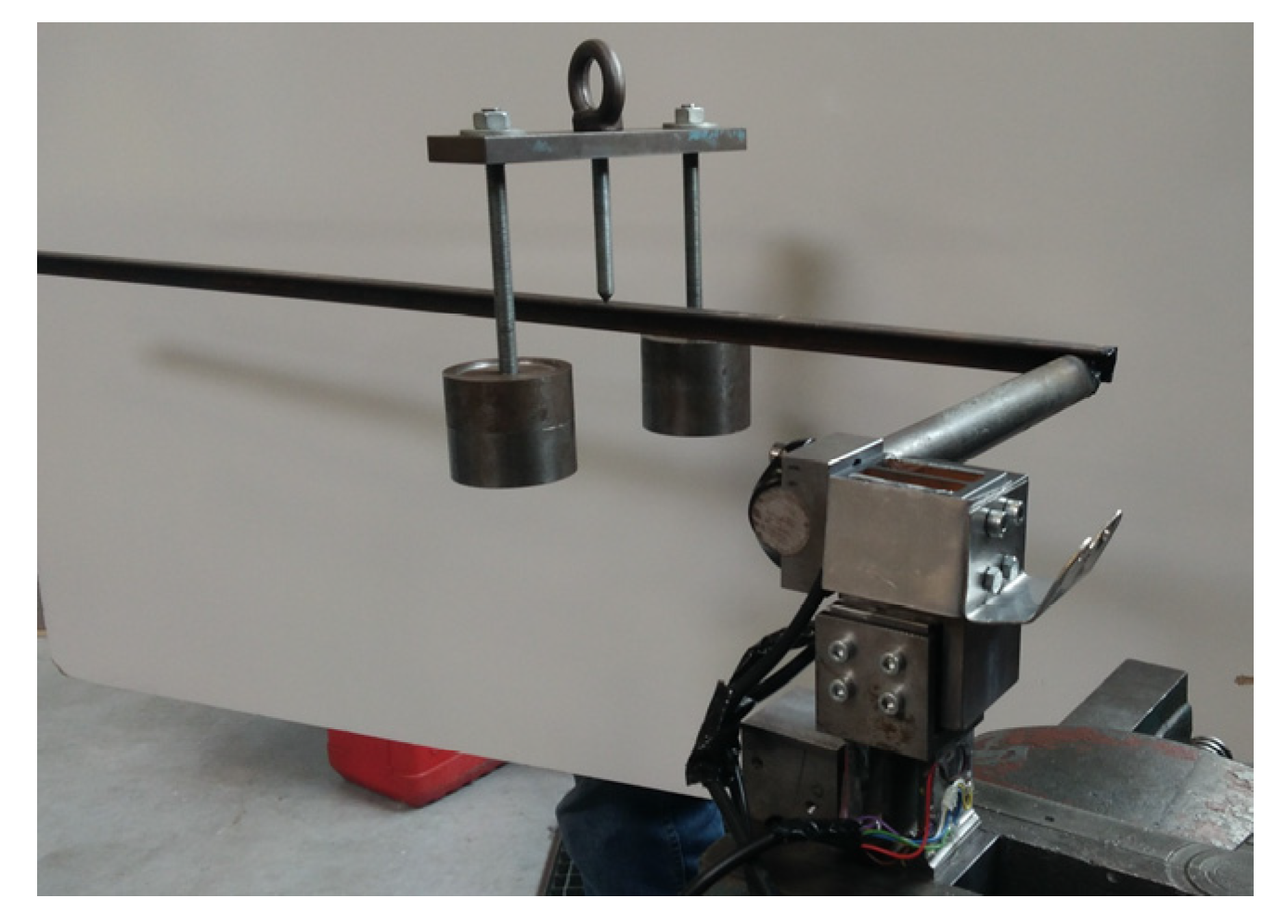
X and Y are the measured signals during calibration and its respective loads. Calibration measurements were obtained applying variating weights on lever lengths combining a force with one or two moments. This was repeated in different orientations with different points of engagement for the weight. The measurements are offset with accompanying measurements done without added weight keeping the signal change due to the load. Figure 4 is one setup of the calibration measurements.
5. Results
Standard error is utilized as an indication of accuracy to compare the calculated loads from the new calibration matrix with the applied loads. The standard errors are given in terms of percentage to the maximum applied load components during calibration [7].
This results as shown in Table 2 in a maximum standard error of 0.5%.
Increasing the number of calibration measurements can improve the accuracy, but this is sufficient for the balance. Unlike other steer measurements this balance can measure the full loads applied on the steer.
References
- Jamerson, F.; Benjamin, E. Electric Bikes Worldwide Report; Notre Dame: Paris, France, 2015. [Google Scholar]
- Drouet, J.M.; Champoux, Y. Development of a three-Lad component instrumented stem for road cycling. In Proceedings of the 9th Conference of the International Sports Engineering Association, Boston, MA, USA, 9–13 July 2012. [Google Scholar]
- Stone, C.; Hull, M.L. Rider/Bicycle Interaction Loads during Standing Treadmill Cycling. J. Appl. Biomech. 1993, 9, 202–218. [Google Scholar] [CrossRef]
- Vanwalleghem, J.; Mortier, F.; De Baere, I.; Loccufier, M.; Van Paepegem, W. Design of an instrumented bicycle for the evaluation of bicycle dynamics and its relation with the cyclist’s comfort. In Proceedings of the 9th Conference of the International Sports Engineering Assosiation (ISEA), Boston, MA, USA, 9–13 July 2012. [Google Scholar]
- Nouri, N.M.; Mostafapour, K.; Kamran, M.; Bohadori, R. Design methodolgy of a six-component balance for measuring forces in water tunnel tests. Measurement 2014, 58, 544–555. [Google Scholar] [CrossRef]
- Yanamashetti, G.; Murthy, H.S. Application of Global Regression method for Calibration of Wind Tunnel Balances. In Proceedings of the Symposium on Applied Aerodynamics and Design of Aerospace Vehicles, Bangalore, India, 16 November 2011. [Google Scholar]
- Blandford, A. Calibration for the Sensitivity Matrix of the Collins Strain Gauge Balance; Platforms Science Laboratory: Melbourne, Australia, 2004. [Google Scholar]
Figure 1.
Steer balance with origin of loads.

Figure 2.
(a) Attached strain gauges on flexural element with (b) Wheatstone bridge measuring the Moment and (c) Wheatstone bridge measuring the Force.
Figure 2.
(a) Attached strain gauges on flexural element with (b) Wheatstone bridge measuring the Moment and (c) Wheatstone bridge measuring the Force.

Figure 3.
FEA Simulation of 790 N load applied on 170 mm.

Figure 4.
Calibration measurement with applied FX, MY and MZ.


Table 1.
loads acquired during road impact and uphill climbing out of saddle with a 3-component balance on the stem of a racing bicycle [2].
Table 1.
loads acquired during road impact and uphill climbing out of saddle with a 3-component balance on the stem of a racing bicycle [2].
| Fz (N) | My (Nm) | Mx (Nm) | |
|---|---|---|---|
| Impact loads | −790 | −32 | 135 |
| Minimum cycling loads | −200 | −10 | −40 |
| Maximum cycling loads | 100 | 30 | 40 |
Table 2.
Accuracy of each component of the balance.
| Component | FZ | MY | MZ | FX | MX | FY |
| Standard Error | 0.38 | 0.30 | 0.53 | 0.20 | 0.50 | 0.21 |
Publisher’s Note: MDPI stays neutral with regard to jurisdictional claims in published maps and institutional affiliations. |
© 2018 by the authors. Licensee MDPI, Basel, Switzerland. This article is an open access article distributed under the terms and conditions of the Creative Commons Attribution (CC BY) license (https://creativecommons.org/licenses/by/4.0/).
Share and Cite
MDPI and ACS Style
D’hondt, J.; Dieltiens, S.; Juwet, M. Design and Calibration of a 6-Component Balance on a Bicycle Steer. Proceedings 2018, 2, 520. https://doi.org/10.3390/ICEM18-05414
AMA Style
D’hondt J, Dieltiens S, Juwet M. Design and Calibration of a 6-Component Balance on a Bicycle Steer. Proceedings. 2018; 2(8):520. https://doi.org/10.3390/ICEM18-05414
Chicago/Turabian StyleD’hondt, Jordi, Sien Dieltiens, and Marc Juwet. 2018. "Design and Calibration of a 6-Component Balance on a Bicycle Steer" Proceedings 2, no. 8: 520. https://doi.org/10.3390/ICEM18-05414