A New Gob-Side Entry Layout Method for Two-Entry Longwall Systems

1
School of Resources and Environmental Engineering, JiangXi University of Science and Technology, Ganzhou 341000, China
2
State Key Laboratory of Coal Resources and Safe Mining, School of Mines, China University of Ming and Technology, Xuzhou 221116, China
3
School of Mining Engineering, Faculty of Engineering, University of New South Wales, Sydney 2052, Australia
*
Author to whom correspondence should be addressed.
Energies 2018, 11(8), 2084; https://doi.org/10.3390/en11082084
Submission received: 24 June 2018
/
Revised: 26 July 2018
/
Accepted: 3 August 2018
/
Published: 10 August 2018
Abstract
:The gob-side entry layout is popular at two-entry longwall mine sites in China for the benefit of improving the coal recovery rate. Currently, two methods have been widely used to develop gob-side entries, including gob-side entry retaining and gob-side entry driving. Gob-side entry retaining maximizes the recovery rate by pillarless mining but increases the difficulty in gob-side entry support. Also, this method has limited applications in hard roof conditions. The gob-side entry driving mine site uses the rib pillar to separate the gob entry and the gob area of the previous panel, which leads to additional coal losses. The waste is more intolerable in large-cutting-height panels and longwall top coal caving panels as the Chinese government limits the minimum recovery rate of longwall panels using these mining methods. In this paper, a new gob-side entry layout method, termed gob-side pre-backfill driving, is established to overcome the shortcomings of the existing methods. The new method eliminates rib pillar losses and enhances gob-side entry stability. The feasibility of gob-side pre-backfill driving is studied by numerical modelling and a field trial at Changcun Mine in China. The results indicate that gob-side pre-backfill driving is an alternative for gob-side entry development. This method is practical and also has the potential to bring significant economic benefits to the mining industry.
1. Introduction
1.1. Background
Longwall coal mining, which refers to fully mechanized longwall mining or longwall top coal caving in this paper, is a highly productive underground coal mining method [1]. This method provides a much higher recovery rate compared with other underground coal mining systems, such as room-and-pillar mining [2]. The reasonable entry layout is essential to both mining safety and maximizing the recovery rate.
The multiple-entry layout (i.e., the use of more than one headgate or tailgate for each longwall panel) with chain pillars (i.e., a series of pillars that are separated by crosscuttings and are developed parallel to the panel entries) separating the entries is popular in longwall coal mines in Australia [3,4]. The chain pillar in this entry layout system is the load-bearing pillar [5], which typically has a minimum width-to-height ratio greater than 8 and is used to sustain the abutment stress induced by longwall panel retreating [6].
The use of wide load-bearing pillars leads to significant coal losses. For example, the longwall panel at Svea Nord Mine has a strike length (i.e., the final retreating distance) of 2500 m with a coal seam thickness of 4 m [7]. The 40-m-wide chain pillars between the adjacent panels at the mine site result in the waste of about 600,000 tons coal resource (assuming the coal density is 1500 kg/m3).
On the contrary, the two-entry layout has been widely applied to coal mines in China. The rib pillar (i.e., a long rectangular pillar the width of which is far less than its length without any crosscuttings that separate the pillar into a series of chain pillars) or the artificial rib pillar is normally used to separate the entry and the gob. The rib pillar in this two-entry system is the yield pillar, which usually has a width of 3–5 m and yields gradually during the retreating of the longwall panel [8]. Two methods are commonly used to develop gob-side entries at Chinese coal mines, including gob-side entry retaining (GER) and gob-side entry driving (GED).
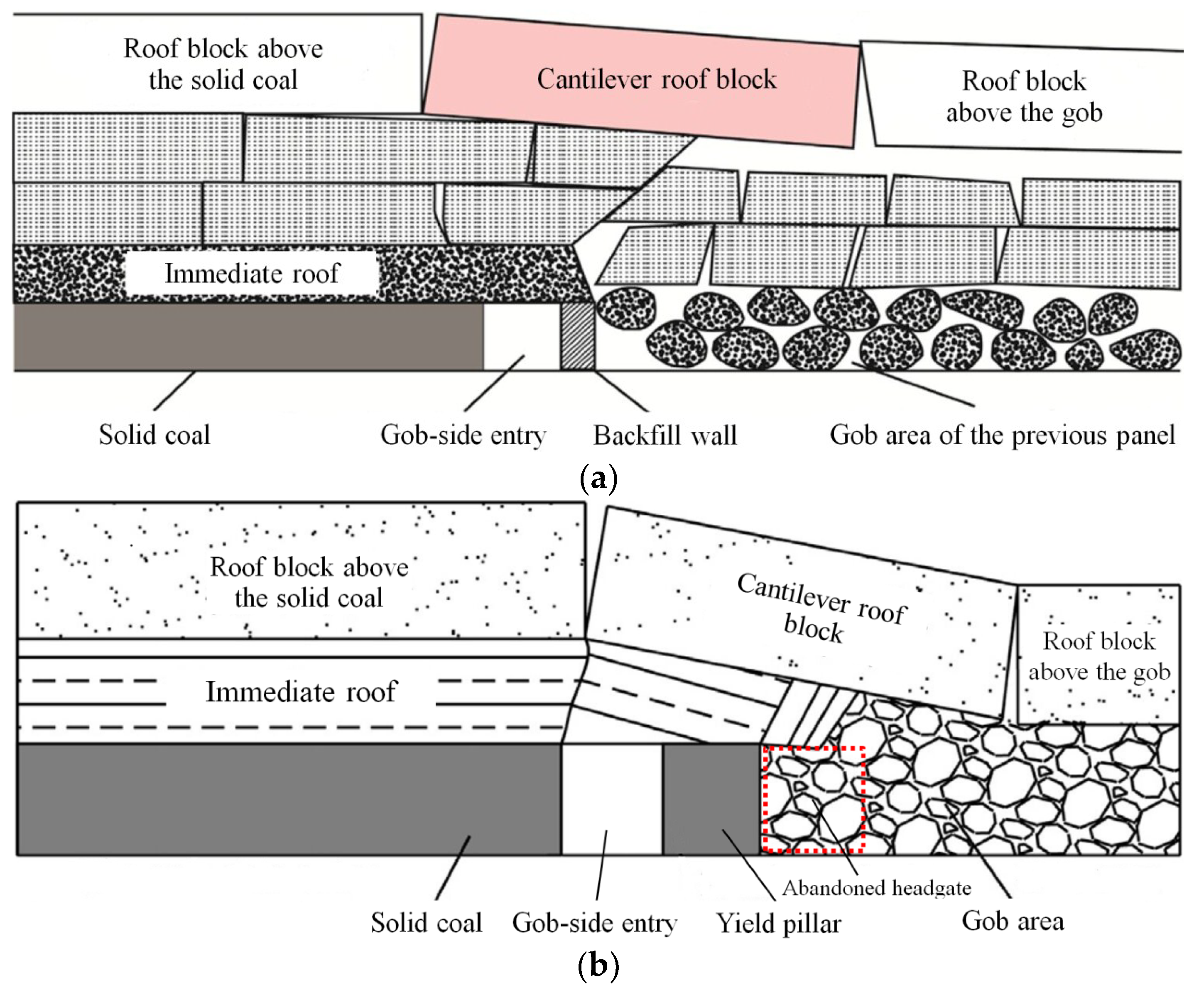
Figure 1a shows the GER entry layout at Xieqiao Mine in China [9]. The headgate of the previous panel is retained after the panel is retreated and will be used as the tailgate of the next panel. Artificial rib pillars, such as gangue backfill [10] and concrete backfill [11], are normally built between the gob-side entry and the gob to prevent poisonous gas flow (from the gob to the entry) and enhance entry stability. Recently, soft–hard artificial rib pillars were used in Tan et al.’s [12] and Wang et al.’s [13] field practice. These authors reported that the soft structure on the top of artificial rib pillar is able to absorb the energy released by roof rotation while the hard structure at the bottom of the artificial rib pillar provides strong resistance. Note that no rib pillar or chain pillar is used in GER practice. Hence, this technique is also called pillarless mining in some literature [14].
Figure 1b shows the GED entry layout at Zhangshuanglou Mine in China [15]. The headgate of the previous panel is abandoned after panel retreating. A gob-side entry is driven along the abandoned headgate with a rib pillar between them as the tailgate of the next panel. The rib pillar is a yield pillar and has similar functions to the artificial rib pillar in GER.
1.2. Previous Studies on Gob-Side Entries
Both GER and GED have numerous applications at mine sites in China (Table 1 and Table 2). The successful field practice indicates the gob-entry layout is able to improve the recovery rate and also ensure mining safety.
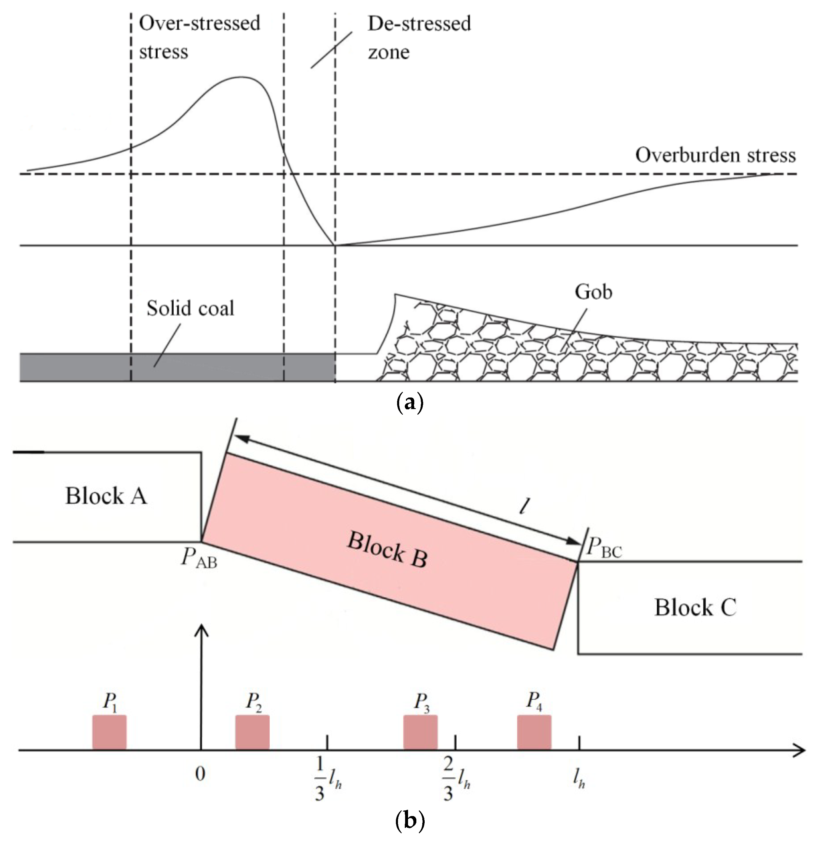
The basic rationale behind early gob-entry practice is the understanding of the redistributed stress state around the gob [15,18,22,29]. The abutment stress induced by panel retreating on the gob-side coal seam distributes nonuniformly. The stress distribution is classified into the destressed zone and the overstressed zone compared with the in situ stress magnitude (Figure 2a) [30]. The gob-side entry should be located in the destressed zone to avoid stress-induced damage and ensure its stability.
Zhang et al. [31] pointed out that the dynamic pressure induced by the main roof block rotation has a much more obvious impact than the abutment stress on gob-side entries. The high dynamic pressure often results in excessive entry deformation and convergence. The cutting cantilever beam theory [32] was proposed to determine the optimal gob-side entry location in GER and the reasonable rib pillar width in GED [9,12,13,16,17,21,23,31,33,34].
As shown in Figure 1, the fractured main roof (due to the previous panel retreating) is divided into three roof blocks, termed Block A (i.e., the block above the solid coal), Block B (i.e., the cantilever block), and Block C (i.e., the block on the gob) respectively [9]. Block A and Block C are supported by the solid coal and gob materials respectively, while gob-side entry stability highly depends on the subsidence and rotation of Block B. Feng and Zhang [9] carried out theoretical analysis on the optimal location of the gob-side entry relative to Block B. They concluded that the gob-side entry is much easier to keep stable if it is located close to the hinge point connecting Block A and Block B (i.e., range P2 in Figure 2b) and the torture of Block B is the dominant force leading to entry instability compared with the resultant vertical force (from both the overburden stress and the weight of Block B). The movement of Block B is insensitive to the entry width, while the resultant vertical force tends to increase as the entry size extends.
Wang et al. [20] and Pi et al. [35] noted that either the artificial rib pillar in GER or the rib pillar in GED should have a reasonable width according to the specific geotechnical condition at a mine site and the increase of the artificial rib pillar width has limited influence on entry stability once it is larger than an optimal value. The width of the rib pillar needs to be carefully determined, otherwise it may be too narrow to maintain stability [25] or too wide to induce stress concentration and cause a potential coal burst accident [36].
Zhang et al. [31] analyzed the case histories at mine sites in China and found that the mining depth is not a key factor on gob-side entry deformation if it is less than 500 m but tends to intensify the deformation once it exceeds 600 m. They also found that the Block B length (Figure 2b) has a significant impact on entry stability. Artificial roof cutting, such as hydraulic fracturing [37], can be used to shorten the Block B length and hence control entry deformation.
The success of gob-side entry support depends on roof control and rib-side reinforcement [18]. Field measurement showed that the roof-to-floor convergence at the artificial rib pillar side in GER [17] or at the rib pillar side in GED [24,38] is much more obvious than that at the solid coal side. Zhang et al. [31] suggested that the minimum roof support resistance and rib-side support resistance should be 0.3 MPa and 0.2 MPa respectively.
1.3. Research Gaps
The GER method maximizes the recovery rate by pillarless mining. However, the gob-side entry in GER:
- is more likely to be close to the gob side, which is outside its optimal location range relative to Block B (i.e., range P2 in Figure 2b);
- suffers twice the dynamic mining pressure induced by the retreating of both panels it serves;
All of the above reasons aggravate gob-side entry stability and increase the support cost.
The use of rib pillars at GED mine sites causes additional coal losses, which can be up to 114,135 tons for the gob-side entry layout between two adjacent panels as listed in Table 3. This issue is more serious in longwall top coal caving panels because the Chinese government regulates that the recovery rate for panels using this mining method must be higher than 75% [15]. Also, an unsuccessful yield pillar design in GER panels may lead to coal burst accidents [36].
Previous studies on gob-side entries are focused on identifying the influencing factors on entry stability. Efforts have been made to optimize the operation parameters, such as determining the reasonable widths of artificial rib pillars in GER and rib pillars in GED and designing practical support schemes for gob-side entries. No attempts have been made to overcome the inherent shortcomings in the existing gob-side layout methods (e.g., support difficulty in GER and rib pillar waste in GED).
In this paper, a new gob-side entry layout method is proposed as an alternative to GER and GED. The new method is introduced in the next section. Then, its feasibility is studied by numerical modelling and tested by an engineering application at Changcun Mine in Section 3 and Section 5 respectively. Finally, some conclusions are made in Section 6.
2. Gob-Side Pre-Backfill Driving
In this section, a new gob-side entry layout method, here termed gob-side pre-backfill driving (GPD), is established. The new method aims to reach the maximum recovery rate by pillarless mining and reduce the support cost by reasonably locating and developing the gob-side entry.
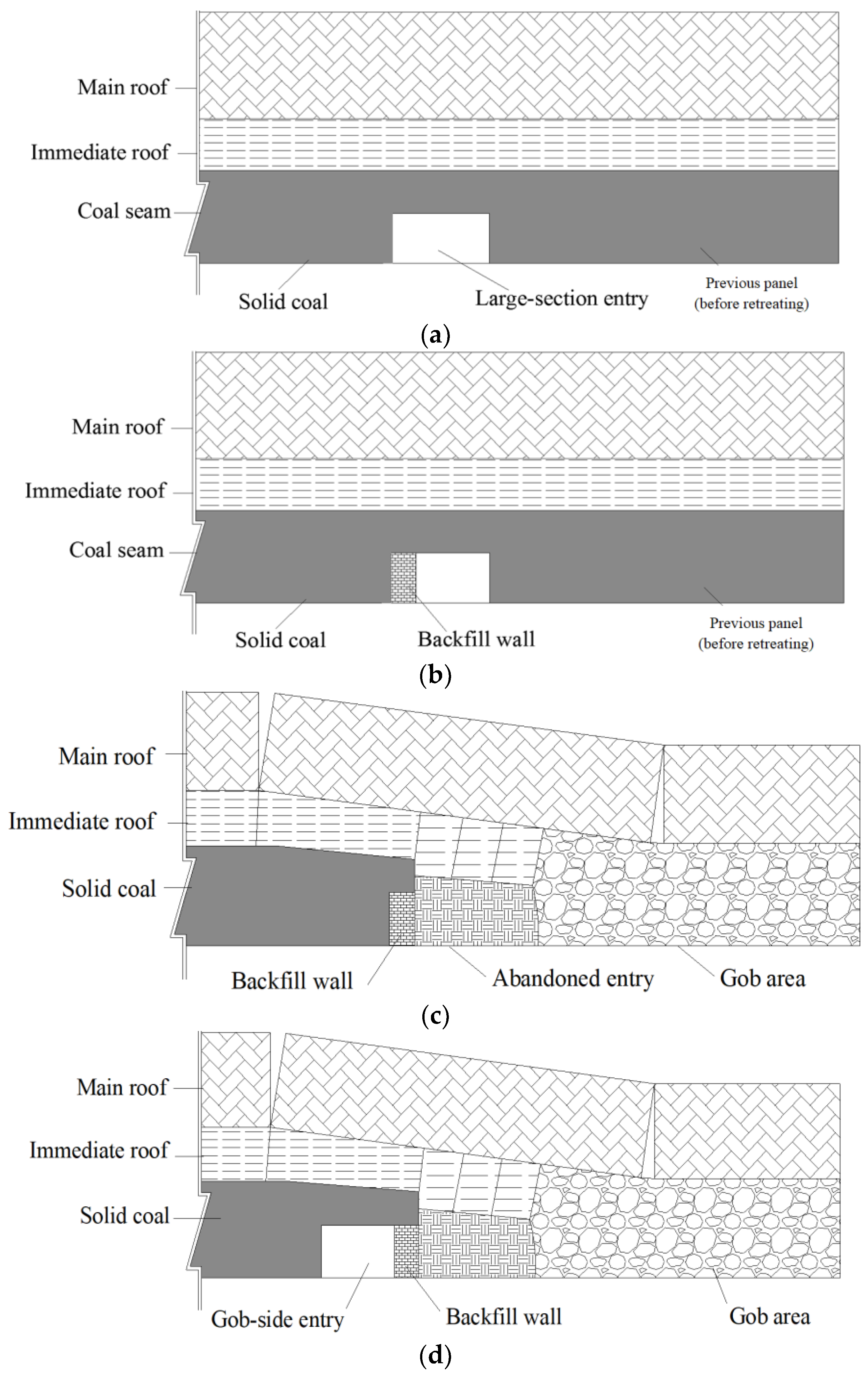
Figure 3 presents the strategies for creating the gob-side entry by GPD. The coal seam thickness in Figure 3 is assumed to be higher than the gob-side entry height, which happens in the large-cutting-height panel or the longwall top coal caving panel. In either of these scenarios, the excavation of the gob-side pillar is essential to improving the recovery rate. The GPD strategies include the following four stages.
- A large-section (in width) entry is created along the previous panel as its headgate (Figure 3a). The entry is wider than the normal headgate, depending on the width of the artificial rib pillar built in the next stage.
- An artificial rib pillar is built along the solid coal side of the large-section entry (Figure 3b).
- The artificial rib pillar must remain stable during and after the retreating of the previous panel, while the other part of the large-section entry is abandoned (Figure 3c).
- The gob-side entry is developed along the artificial rib pillar (at the solid coal side) as the tailgate of the next panel (Figure 3d).
3. Modelling Study of the Feasibility of Gob-Side Pre-Backfill Driving
In Section 2, the concept of gob-side pre-backfill driving (GPD) is proposed to fill the research gaps existing in GER and GED. This newly developed gob-side entry layout method will be applied to Changcun Mine in China (Section 5). Before the field application, the feasibility of GPD is studied based on the geotechnical condition at Changcun Mine by numerical modelling. The modelling study aims to:
- examine artificial rib pillar stability during the retreating of the previous panel (Figure 3c) and determine the optimal artificial rib pillar width and strength;
- investigate the stress distribution around the gob-side entry during entry development (Figure 3d);
- evaluate the stress distribution around the gob-side entry during the retreating of the next panel;
- provide recommendations on the field application.
3.1. Modelling Assumptions and Input Parameters
The commercial numerical modelling code Fast Lagrangian Analysis of Continua (FLAC) 3D is used to conduct the numerical simulations. The code (in both 2D and 3D versions) has been used to simulate the longwall mining process and analyze entry stability in previous studies by various authors [7,11,15,25,29]. The following constitutive models are used in the numerical simulations in this paper:
- The strain-softening approach is used to simulate the artificial rib pillar [22].
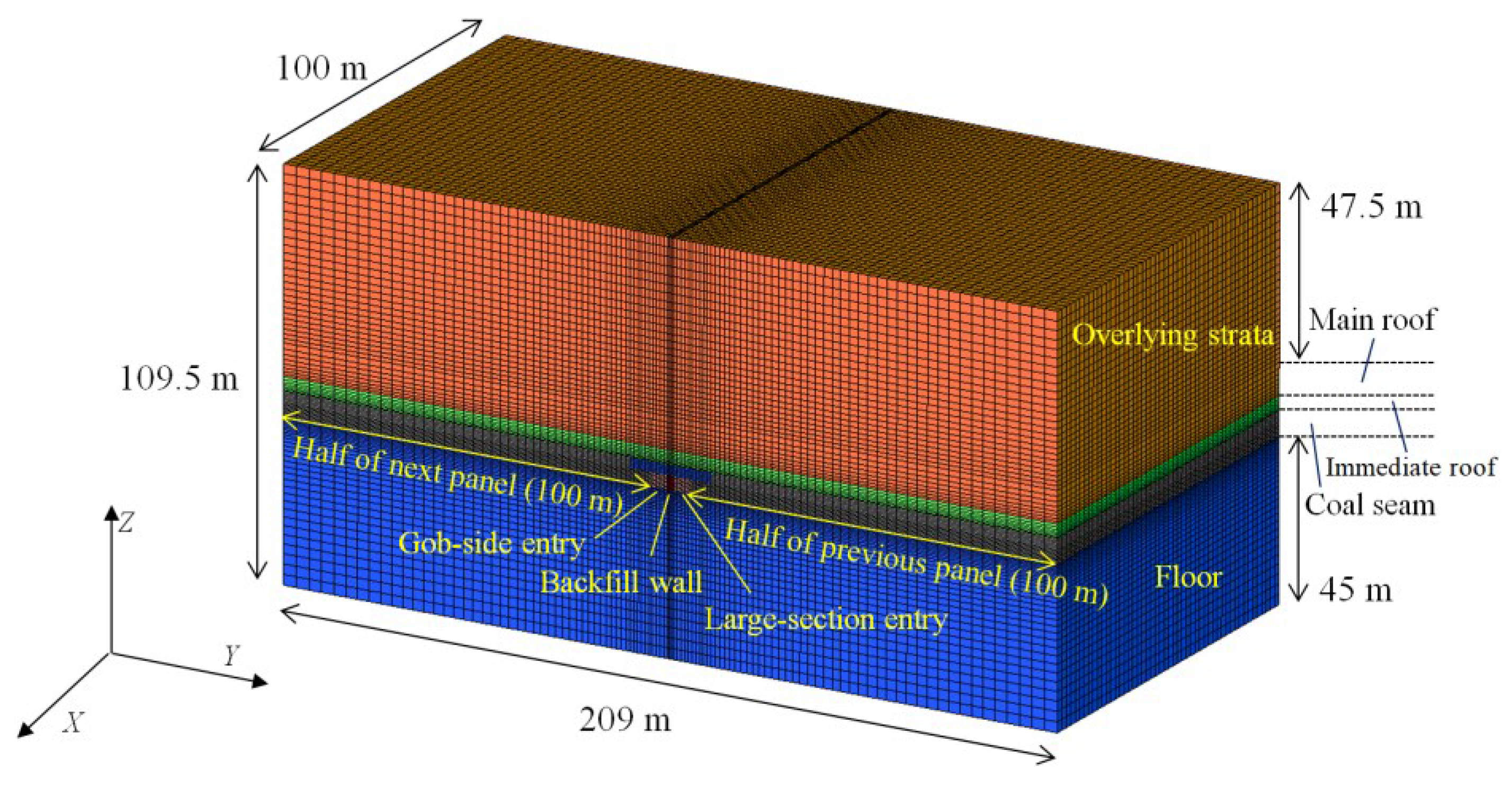
The coal seam at Changcun Mine has a dip angle ranging from 0° to 6° and is assumed to be horizontal in the numerical simulation. Figure 4 shows the numerical model. The model has dimensions of 209 m × 100 m × 109.5 m. The coal seam average thickness is 6.1 m with a mining height of 3.2 m. Both the large-section entry (Figure 3a) and the gob-side entry (Figure 3d) have dimensions of 4.5 m (in width) × 3.5 m (in height). The artificial rib pillar is assumed to be continuous along the strike length of the longwall panel in the numerical simulation.
Table 4 shows the roof and floor strata at Changcun Mine. Table 5 provides the mechanical properties of the coal and the rocks.
The mining depth is about 450 m. A 9.75 MPa compressive stress boundary condition is applied to the top surface of the numerical model to simulate the overburden stress (assuming the density of the overburden strata is 2500 kg/m3). The horizontal in situ stresses are 8.25 MPa and 10.17 MPa respectively with the maximum horizontal in situ stress being perpendicular to the panel retreating direction (i.e., the Y axis in Figure 4) [41].
3.2. Artificial Rib Pillar Stability during Previous Panel Retreating
The artificial rib pillar is built along the solid coal side of the large-section entry before the retreating of the previous panel (Figure 3b). The entry is abandoned after panel retreating (Figure 3c), while the artificial rib pillar must remain stable as the gob-side entry will be driven along it in the next stage (Figure 3d). Concrete is used to build the artificial rib pillar at this stage for its low cost and satisfactory efficiency. Table 6 lists concrete mechanical properties with different concrete grades. These types of concrete are used in the following modelling scenarios since they are commonly used in the coal mining industry for the purpose of building artificial rib pillars.
3.2.1. Effect of Artificial Rib Pillar Width
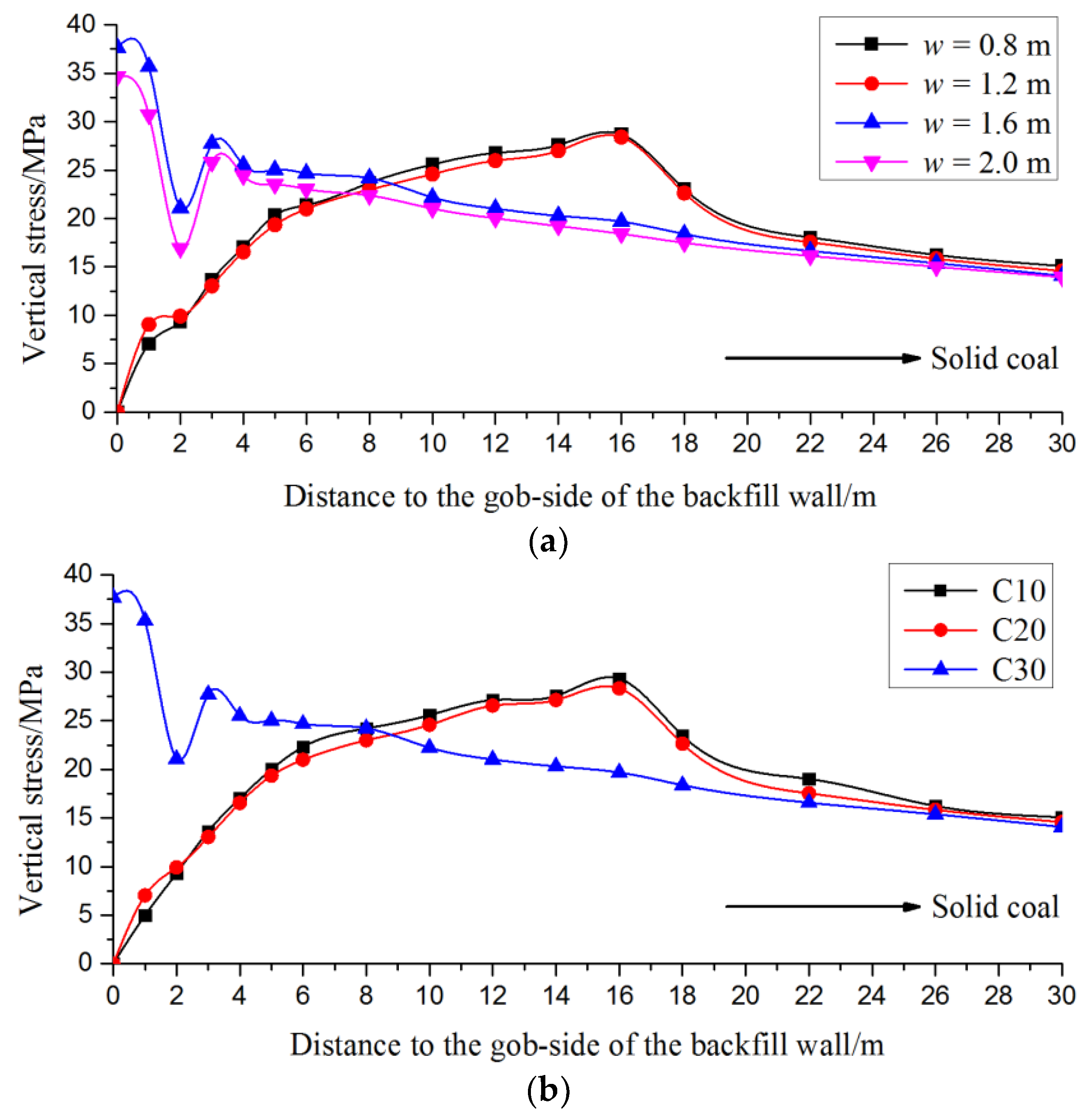
Deng et al. [11] verified the reliability of concrete backfilling in the GER application at Jingang Mine in China. The compressive strength of the concrete in Deng’s et al. [11] field test was about 23.5 MPa. In numerical modelling Set 1, C30 concrete (Table 6) is assumed to create the artificial rib pillar. The stress distributions around the artificial rib pillars having different widths (w) are compared (Table 7).
The panel is simulated to be mined completely and filled with gob materials. To present the simulation results, first, a section plane is chosen. The section plane is parallel to the Y-Z plane (Figure 4) and passed through the model center. Then, a horizontal line on this section plane is used. The horizontal line coincides with the top level of the artificial rib pillar, and the vertical stresses at points along this line are recorded for analysis.
The simulated stress distributions in Cases 1-1 to 1-4 (i.e., artificial pillar widths change from 0.8 to 2.0 m with an interval of 0.4 m) are superimposed in Figure 5a. The redistributed stress state in Case 1-1 (w = 0.8 m) is very close to that in Case 1-2 (w = 1.2 m). In both cases, the artificial rib pillars fail and lose their loading capacities. The abutment stress in each case is transferred into the inner part of the solid coal (about 16 m away from the artificial rib pillar), which provides a de-stressed zone for the development of the gob-side entry. However, the failed artificial rib pillar tends to collapse during gob-side entry development.
In Cases 1-3 (w = 1.6 m) and 1-4 (w = 2 m), the artificial rib pillars remain stable and possess high loading capacities. The stress distributions in both cases exhibit the same tendency. Compared with Case 1-3, the larger top surface of the artificial rib pillar in Case 1-4 decreases the maximum vertical stress applied to the artificial rib pillar surface. This implies the artificial rib pillar becomes more stable with a higher width-to-height ratio.
The abutment stresses in Cases 1-3 and 1-4 concentrate on the artificial rib pillar and drop suddenly at the edge of the solid coal. Then, the stresses increase again towards the solid coal side until they reach their peak values. This indicates the solid coal close to the artificial rib pillar side partly fails due to the abutment stress and transfers the abutment stress into the inner part.
3.2.2. Effect of Artificial Rib Pillar Strength
Lower-grade concrete can be used to build the artificial rib pillar in order to reduce the operating cost. From the modelling results in Section 3.2.1, artificial pillar widths smaller than 1.6 m (i.e., 0.8 m in Case 1-1 and 1.2 m in Case 1-2) fail to maintain artificial pillar stability if C30 concrete is used. This implies artificial pillars having widths smaller than 1.6 m can hardly remain stable if C10 concrete or C20 concrete is used since these types of concrete have lower strength compared with C30 concrete. In numerical modelling Set 2, the artificial rib pillar width is assumed to be 1.6 m. The concrete grades in Cases 2-1 to 2-3 are C10, C20, and C30 respectively to test the artificial rib pillar stability with different concrete strength (Table 7).
The simulated stress distributions in Cases 2-1 to 2-3 are superimposed in Figure 5b. The results of Cases 2-1 and 2-2 show that the artificial rib pillars built by lower-grade concrete lose loading capacities and transfer the abutment stress to the solid coal side. The maximum vertical stresses in both cases occur at a distance about 16 m away from the artificial rib pillar.
The stress distributions in Case 1-1 (w = 0.8 m with C30 concrete), Case 1-2 (w = 1.2 m with C30 concrete), Case 2-1 (w = 1.6 m with C10 concrete), and Case 2-2 (w = 1.6 m with C10 concrete) exhibit similar tendencies, which shows that both the artificial rib pillar width and concrete strength are critical factors on artificial rib pillar stability. From the simulation results, a 1.6-m-wide artificial rib pillar built by C30 concrete is reasonable for the field trial.
3.3. Stress Distributions after Gob-Side Entry Development
A reasonable width (Section 3.2.1) and sufficient strength (Section 3.2.2) are essential to artificial rib pillar stability during first panel retreating. In the following simulations, C30 concrete is used to simulate a 1.6-m-wide artificial rib pillar. The stress distributions after gob-side entry development and during next panel retreating are analyzed in Section 3.3 and Section 3.4 respectively.
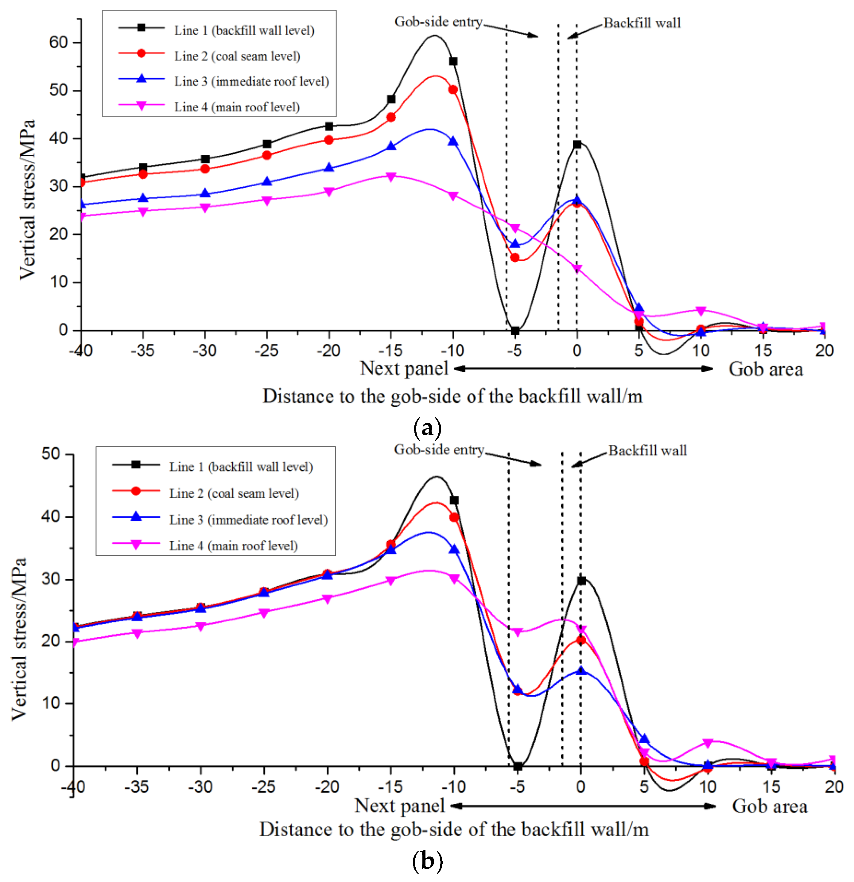
Four horizontal measurement lines (parallel to the Y-Z plane in the numerical model) are used to record the stress magnitudes calculated from the numerical simulations (Figure 6a). Lines 1 to 4 align with the top levels of the artificial rib pillar, the coal seam, the immediate roof, and the main roof respectively.
Figure 6b shows the vertical stress distributions along Lines 1 to 4 after gob-side entry development. The vertical stresses along Line 1 are redistributed compared with that before gob-side entry development. Gob-side entry excavation relieves the vertical stresses applied around the gob-side entry roof area and transfers them into the solid coal side. The maximum vertical stress applied to the artificial rib pillar decreases from 37.7 MPa to 30.4 MPa, while the maximum vertical stress applied to the solid coal increases from 22.2 MPa to 25.5 MPa with its location being 5 m away from the entry side.
The vertical stress distribution along Line 2 shows a similar tendency to that along Line 1. The vertical stresses applied to the top level of the coal seam are generally lower than that applied to the Line 1 level with the exception of that above the entry roof.
The vertical stress distributions along Lines 3 and 4 indicate that gob-side entry development has limited influence on both the immediate roof and the main roof. The vertical stresses applied to Lines 3 and 4 are generally lower than that applied to Lines 1 and 2 with their peak values occurring closer to the gob-side entry.
Figure 6b presents the horizontal stress distributions along Lines 1 to 4. The horizontal stress distributions along the measurement lines are quite different from each other in the region above the artificial rib pillar. The maximum horizontal stress (14.4 MPa) among Lines 1 to 4 occurs at the top level of the immediate roof (Line 3), which should be because of the torque of the fractured main roof (due to first panel retreating) on the immediate roof. In the region above the artificial rib pillar, the maximum horizontal stress along Line 1 (9.89 MPa) is about twice of that along Line 2. This implies the top coal above the artificial rib pillar is damaged due to the abutment stress induced by first panel retreating and the horizontal stress is transferred into the solid coal side (Line 2 in Figure 6c). The more competent artificial rib pillar (compared with the top coal) remains steady and sustains a certain horizontal stress (about 10 MPa), which acts as the confining pressure and favours artificial rib pillar stability.
3.4. Stress Distributions during Next Panel Retreating
From the field monitoring at previous longwall panels at Changcun Mine, the working face first weighting interval is about 37.8 m [42]. In the numerical simulation, the retreating distance of the next panel is assumed to be 40 m without gob materials filling the gob area. The vertical stress distributions along Lines 1 to 4 (Section 3.3) 5 m and 15 m ahead of the working face are investigated respectively.
Figure 7a shows the simulation results 5 m ahead of the working face. The maximum vertical stress along the top level of the artificial rib pillar (Line 1) is transferred to the solid coal side (compared with that in Figure 6b) and reachs a magnitude of 56.2 MPa at the location 5 m away from the entry side. The stress concentration factor increases to about 5 due to the superimposition of the side abutment stress of the previous panel and the front abutment stress of the next panel. The vertical stress increment at the artificial rib pillar is less obvious (from 30.4 MPa to 38.8 MPa). The reason should be that the large deformation and subsidence of the immediate roof and the top coal above the artificial rib pillar transfer the high abutment stress to the solid coal side.
The vertical stress distributions along Lines 2 and 3 are similar to that along Line 1 with the maximum vertical stress at the top level of the coal seam (Line 2) increasing from 24.4 MPa to 50.3 MPa and the maximum vertical stress at the top level of the immediate roof (Line 3) increasing from 22.5 MPa to 39.3 MPa both at the location 5 m away from the entry side.
The vertical stresses at the top level of the main roof change smoothly in the region above the solid coal with the maximum magnitude reaching 32.2 MPa at the location 10 m away from the entry side.
Figure 7b gives the vertical stress distributions 15 m ahead of the working face. The maximum vertical stress along Line 1 occurs at the solid coal side and decreases from 56.2 MPa to 42.7 MPa compared with that 5 m ahead of the working face. Also, the maximum vertical stress applied to the artificial rib pillar decreases from 38.8 MPa to 29.8 MPa. This indicates the stress concentration at the section 15 m ahead of the working face is much lower than that 5 m ahead of the working face.
4. Advantages of Gob-Side Pre-Backfill Driving over Gob-Side Entry Retaining and Gob-Side Entry Driving
Table 8 shows the differences between GPD, GER, and GED. Both GPD and GER use artificial rib pillars instead of rib pillars as the barriers between gob-side entries and the gob area of the previous panel, which maximizes the recovery rate. The gob-side entry location in GPD could be controlled by enlarging the large-section entry width (Figure 3a) to put the entry in an optimal position relative to Block B (Figure 2b). Also, the GPD gob-side entry only suffers the abutment stress induced by the next panel, which further decreases the support cost.
The GPD strategies are similar to that in GED. The rib pillar used in GED is replaced by the artificial rib pillar built along the large-section entry in GPD (Figure 3a). This reduces mining costs by eliminating rib pillar loss, as evidenced by the field trial presented in Section 5. Coal is a highly heterogeneous material [43]. Its heterogeneity affects rib pillar strength [44] and also makes the coal outburst threshold more difficult to be quantified [45].
5. Field Trial at Changcun Mine
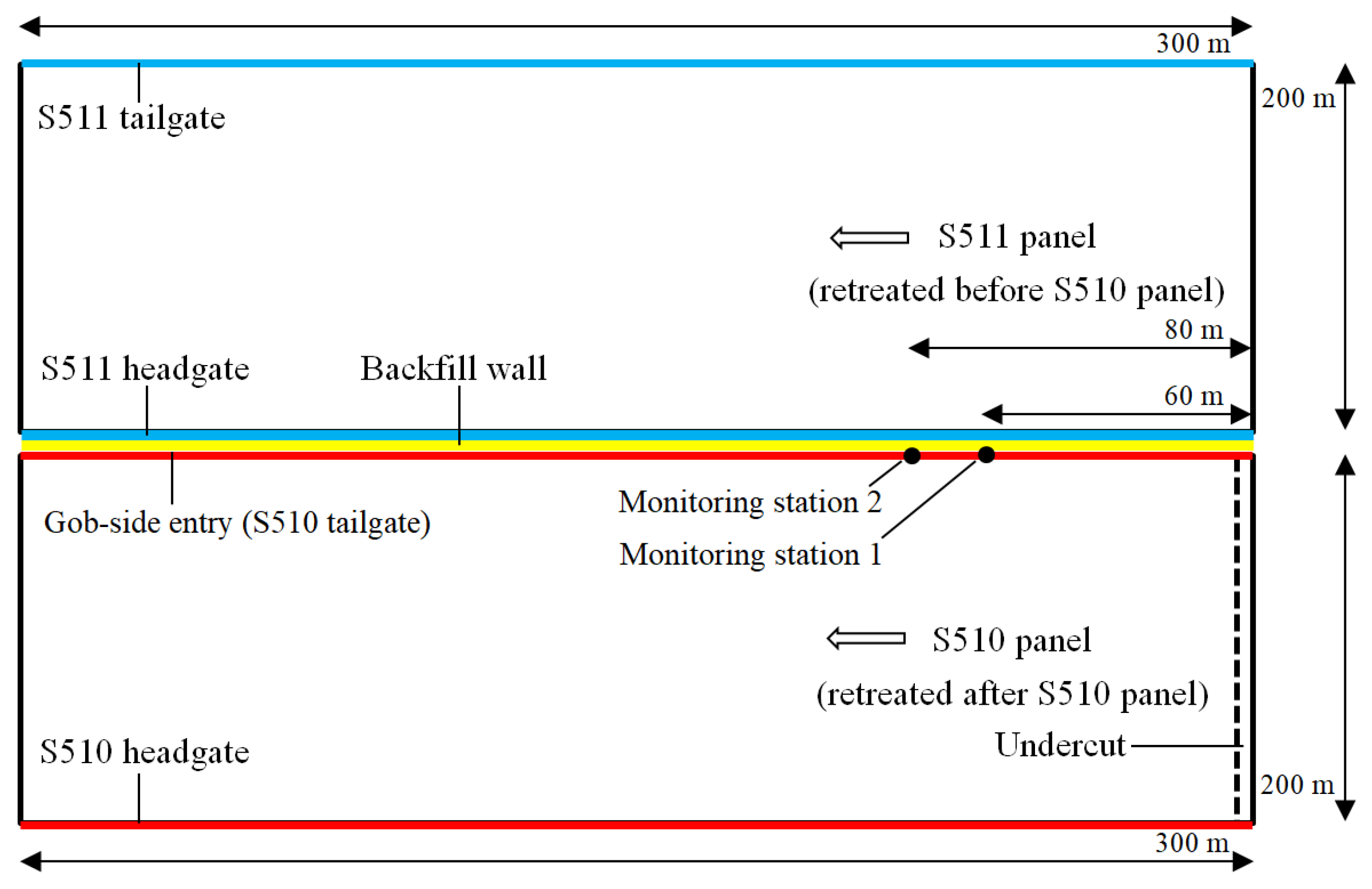
The GPD method is applied to develop the gob-side entry between S511 panel (the previous panel in Figure 3a) and S510 panel (the next panel in Figure 3d) at Changcun Mine in China. The geotechnical condition at the mine site is provided in Section 3. In the field trial, both panels have a final retreating distance of 300 m (Figure 8). The S510 tailgate is drilled six months after the S511 panel has been retreated.
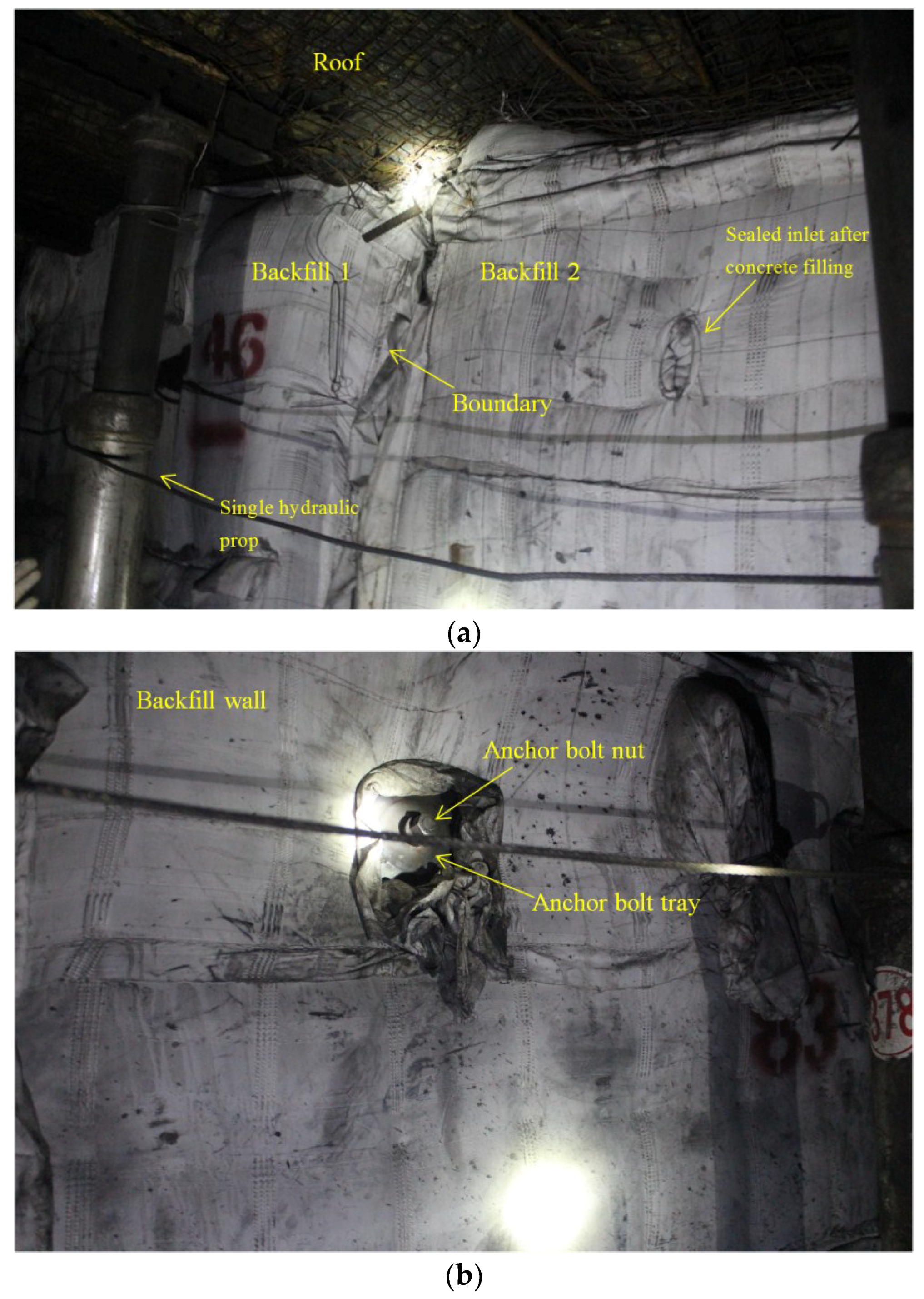
The large-section headgate in S511 panel has dimensions of 4.5 m (in width) × 3.5 m (in height). C30 concrete is used to build a 1.6-m-wide artificial rib pillar (determined by the numerical simulations in Section 3.2) along the headgate at the side close to S510 panel. The artificial rib pillar is formed by a series of backfills as shown in Figure 9a. Each backfill is created by injecting C30 concrete slurry into the backfill bag from the inlet. Each backfill has dimensions of 1.6 m (in width) × 3 m (in length) × 3.5 m (in height). One hundred backfills are used in total to construct the artificial rib pillar. Nine anchor bolts are used to strengthen each backfill with their orientations being perpendicular to the entry axis (Figure 9b).
The artificial rib pillar remains stable during the retreating of S511 panel. Then, the gob-side entry is driven along the artificial rib pillar as the tailgate of S510 panel. The gob-side entry has dimensions of 4.5 m (in width) × 3.5 m (in height). The support schemes for the gob-side entry, the field monitoring results, and the artificial rib pillar costs are given in the following sections.
5.1. Gob-Side Entry Support Schemes
5.1.1. General Permanent Support
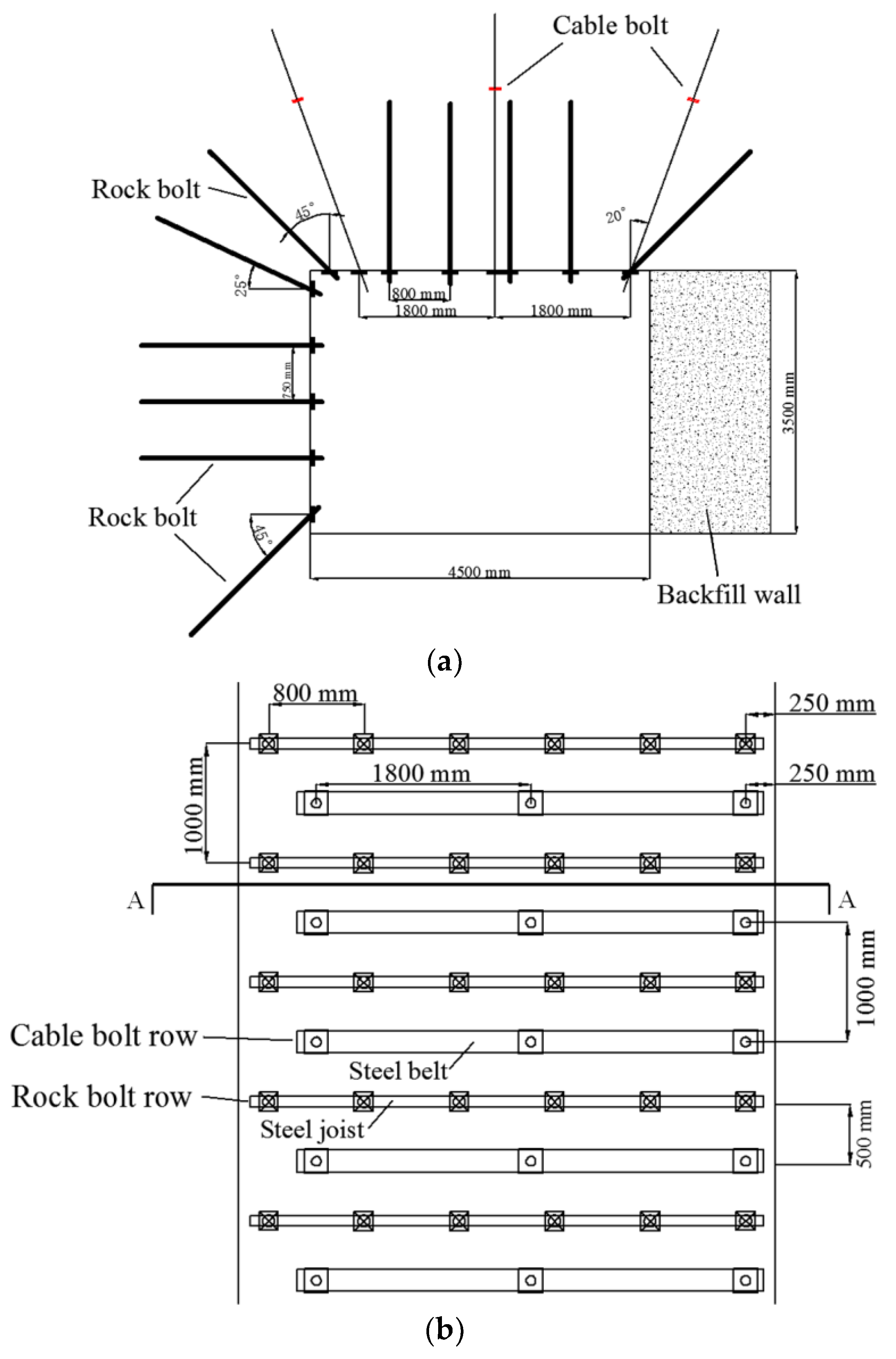
Pre-stressed rock bolts (2.4 m in length) [46] are used to support the gob-side entry roof with a row spacing of 1000 mm and a bolt spacing of 800 mm. The rock bolt has a pre-stressed force of 40–50 kN, an anchoring force of 150 kN, and tightening torque of 300 N·m. In each row, the four rock bolts at the middle are arranged vertically towards the roof and the two rock bolts at the solid coal side and the artificial rib pillar side respectively are arranged obliquely with a dip angle of 45° (Figure 10a). Steel joists are used to connect the rock bolts in each row.
Cable bolts are used to tighten up the roof layers in order to improve their loading capacities and decrease the compression on the artificial rib pillar. Three cable bolts (with a cable bolt borehole diameter of 17.8 mm and a bolt length of 8300 mm) are arranged in each cable bolt row with a spacing of 1800 mm. The cable bolts in each row are connected by a steel belt and are arranged close to the artificial rib pillar (Figure 10b). The cable bolt rows have a spacing of 1000 mm and are located at the middle of the rock bolt rows (Figure 10b).
5.1.2. Recoverable Side Support
Rock bolts are used to support the solid coal side of the gob-side entry (Figure 10a). The rock bolts are recoverable and are released once the shearer (i.e., the cutting machine) approaches the entry side [47]. Five rock bolts are arranged in each rock bolt column with a spacing of 750 mm. In each rock bolt column, the rock bolt close to the roof side has an inclination angle of 25° towards the roof, while the rock bolt close to the floor side has an inclination angle of 45° towards the floor. Other rock bolts are arranged horizontally towards the solid coal. The rock bolt has a length of 2.4 m, and the rock bolt column spacing is 1000 mm.
5.1.3. Advanced Temporary Support
Advanced temporary support is used to strengthen the gob-side entry roof in the area 40 m ahead of the working face, including the use of single hydraulic props, joists, and boards (Figure 11).
Four single hydraulic props are used in each row with two of them located close to the solid coal side and others located close to the artificial rib pillar side. The props at each side has a spacing of about 0.8 m. The prop row spacing is 1 m.
Four steel joists are laid on the prop tops between every two prop rows with their orientations being parallel to the entry axis. Two boards are located above the steel joists with their longer axes being perpendicular to the entry axis.
5.2. Field Monitoring
5.2.1. Monitoring Approaches
Two monitoring stations are arranged in the gob-side entry. Station 1 and Station 2 are located 60 m and 80 m ahead of the undercut respectively (Figure 8). The field monitoring aims to measure the following data during the retreating of Panel S510:
5.2.2. Gob-Side Entry Deformation
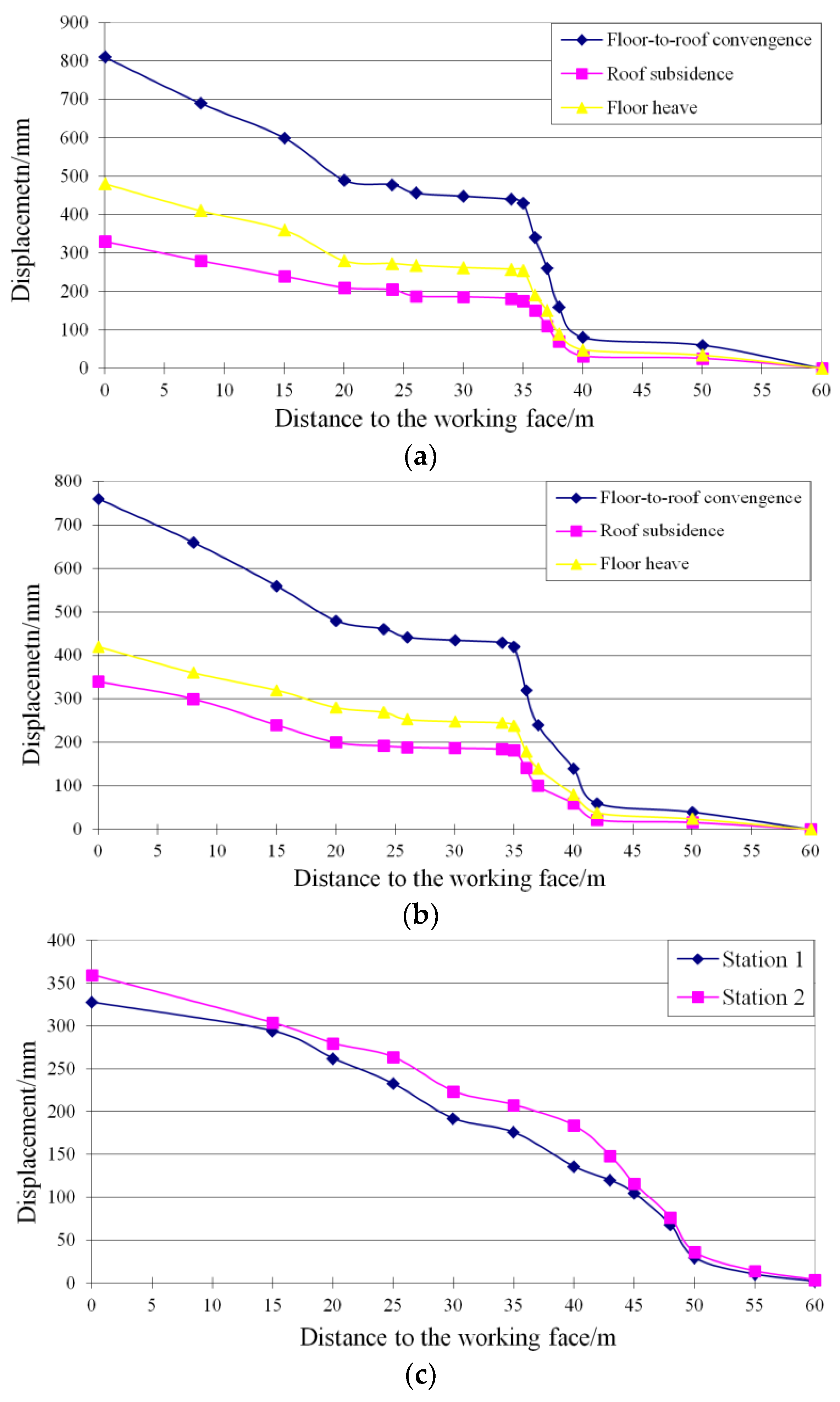
Figure 12 presents the roof, floor, and side displacements recorded from Stations 1 and 2 during S510 panel retreating. When the retreating distance reachs 20 m, the roof and floor deformation at Station 1 (60 m away from the undercut) is limited, with the maximum roof-to-floor convergence being 80 mm (Figure 12a), while the deformation at Station 2 (80 m away from the undercut) is negligible (Figure 12b). The entry deformation at Station 1 increases dramatically with panel retreating, and the increment becomes steady once the working face is 35 m away from the station. The roof and floor deformation at Station 2 also shows the same tendency.
The roof and floor displacements at both Stations 1 and 2 change slightly when the working face to station distance ranges from 20 to 35 m. This implies the advanced temporary support (Section 5.1.3) is effective in controlling surrounding rock deformation.
When the working face advances closer to each station, the recorded roof and floor displacements increase again. The average roof-to-floor convergence from both stations reaches 785 mm with the average roof subsidence and roof heave being 335 mm (42.7%) and 450 mm (57.3%) respectively.
The entry side displacements recorded from Stations 1 and 2 are superimposed in Figure 11c for comparison. The side deformation at each station shows the same tendency. The side displacements at Stations 1 and 2 begin to increase notably once the working face to station distance is 50 m and arrive at the final maximum values of 328 and 360 mm respectively.
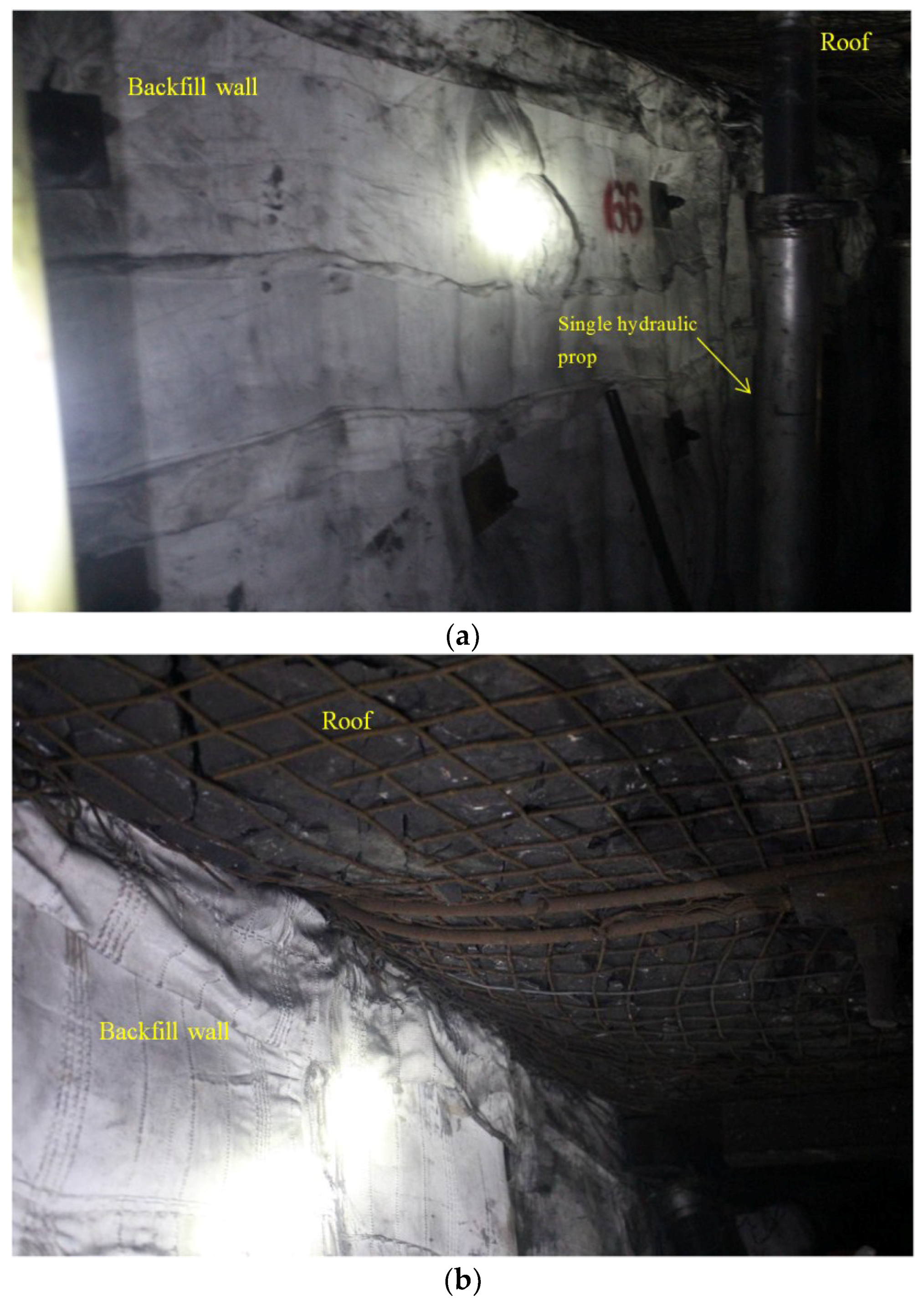
The monitoring results at Stations 1 and 2 indicate the gob-side entry deformation is allowable. This is also evidenced by the field observation provided in Figure 13. Figure 13a,b present the artificial rib pillar condition and the gob-side entry roof condition respectively. The cost-effective support schemes in Section 5.1 (compared with that in GER) are satisfactory. The gob-side entry remains stable during next panel retreating, and its deformation has a limited impact on working conditions.
5.2.3. Rock Bolt and Cable Bolt Loading
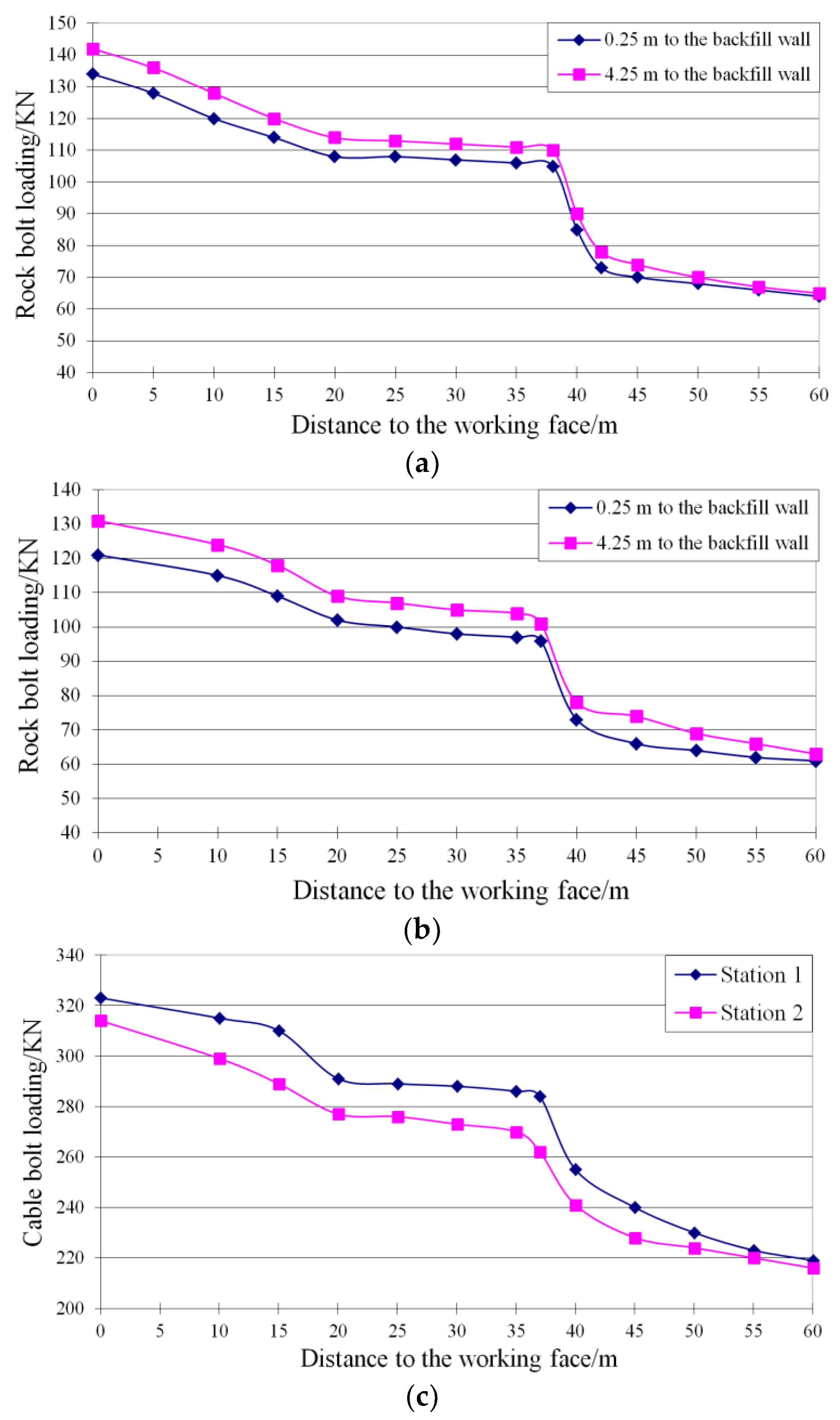
Two dynamometers are used to detect the rock bolt loadings at each monitoring station, including one attached to the rock bolt close to the artificial rib pillar side (0.25 m to the artificial rib pillar) and the other attached to the rock bolt close to panel side (4.25 m to the artificial rib pillar) (Figure 10).
The rock bolt loading forces monitored at Stations 1 and 2 are superimposed in Figure 14a,b respectively. The loading force variation of each rock bolt shows the same tendency, including four stages. First, the rock bolt loading force changes slightly when the working face to station distance ranges from 42 to 60 m. Then, the load force increases dramatically before the working face is 38 m away from the station. The increment implies the rock bolt deforms in tension to control the entry roof subsidence caused by the front abutment stress. In the third stage, the loading force changes of the rock bolts at both stations become steady. This indicates that the advanced temporary support has a significant effect on controlling roof subsidence. Once the working face is 20 m away from the station, the rock bolt loading force begins to increase again until it reaches the maximum value.
The loading force of the cable bolt at the middle of the bolt row is monitored at each station. The results are given in Figure 14c. The variation of the cable bolt loading force shows a similar tendency to that of the rock bolt, which indicates the cable bolt is efficient in tightening the roof strata and controlling roof subsidence.
The maximum rock bolt loading forces at Stations 1 and 2 are 142 and 132 kN respectively, which are lower than the maximum rock bolt breaking load (186.3 kN). Also, the maximum cable bolt loading forces at Stations 1 and 2 are 323 and 314 kN respectively, which are below the maximum cable bolt breaking load (355 kN).
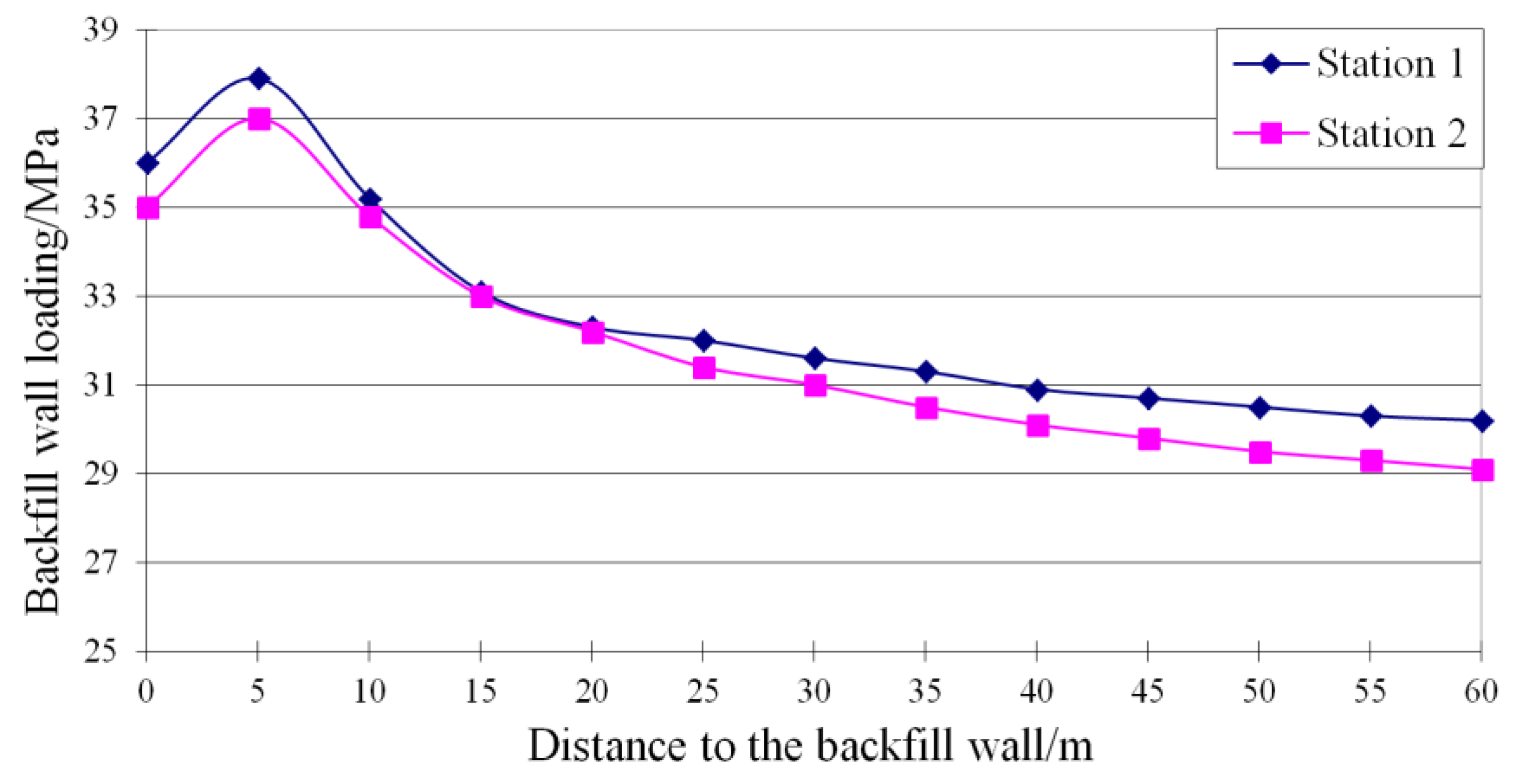
5.2.4. Artificial Rib Pillar Loading
Stress gauges are embedded in the top surface of the artificial rib pillar at each monitoring station to record the artificial rib pillar loading during S511 panel retreating. The compressive stresses applied to the artificial rib pillar at Stations 1 and 2 are superimposed in Figure 15. The compressive stresses monitored at both stations increase gradually with panel retreating and reach the maximum magnitudes of 37.9 MPa (Station 1) and 37 MPa (Station 2) respectively when the working face to station distance reaches about 5 m. Then the loading forces decreas slightly to 36 MPa (Station 1) and 35 MPa (Station 2) respectively.
In general, the compressive stresses applied on the artificial rib pillar top change smoothly during S511 panel retreating. The deformation of the top coal and the immediate roof is likely to transfer the abutment stress from the artificial rib pillar to the solid coal side.
5.3. Artificial Rib Pillar Cost
Table 9 gives the operating cost of the artificial rib pillar per 1-m panel retreating distance. The total cost reaches 380 USD. Concrete cost accounts for the largest proportion, which is up to 79.8%. Note that the operating cost of the artificial rib pillar is not for global mining but only for the local market that tends to use the GPD method.
Table 10 compares the operating cost of GPD relative to GED based on the conditions at Changcun Mine. Note that the coal seam average height is 6.1 m and the gob-side entry height is 3.5 m. The top coal above the gob-side entry roof is not recovered. Hence the additional coal losses caused by GED in Table 10 are calculated based on the gob-side entry height. The coal density and unit price in Table 10 are assumed to be 1400 kg/m3 and 54 USD/ton respectively.
The 1.6-m-wide artificial rib pillar built between the trial panels (having a final retreating distance of 300 m) costs 114,186 USD, which saves 13,488 (127,674–114,186) USD if GED is used with a rib pillar having the same width. Note that coal has much lower strength than concrete and a 1.6-m-wide rib pillar is not practical to maintain entry stability (Section 3.2.2). From the previous experience at GED mine sites in China (Table 3), the rib pillar width may be up to 5 or 8 m. In these cases, the additional coal losses caused by GED increases accordingly and could reach 638,140 USD.
The panel strike length also affects the additional coal losses in GED. Longwall panel lengths are generally up to 1000 m and could reach about 3000 m in some cases (Table 1 and Table 2). This further increases the coal losses and may lead to a notable economic loss of 5,317,829 USD in the case that an 8-m-wide rib pillar is retained between two 2500-m-long panels as listed in Table 10. The artificial rib pillar cost of GPD in this case is 951,550 USD, which brings an economic benefit of 4,363,911 USD.
6. Conclusions
Gob-side entries are popular in two-entry longwall systems, as well as some multiple-entry longwall systems [22,29], at coal mine sites in China. The use of gob-side entries significantly improves the recovery rate compared with wide load-bearing pillars that are normally used in longwall systems in Australia. Two methods have been commonly used in current gob-side entry applications, including gob-side entry retaining (GER) and gob-side entry driven (GED). In this paper, previous studies on gob-side entries are summarized and the research gaps are identified. A new gob-side entry layout method is proposed as an alternative to the existing methods with the purposes of overcoming the shortcomings of both GER and GED.
In the new method, termed gob-side pre-backfill driving (GPD), an artificial rib pillar is pre-created along the headgate of the previous panel. Then a gob-side entry is driven along the artificial rib pillar as the tailgate of the next panel. GPD reduces coal losses by pillarless mining and also favours gob-side entry stability. Its feasibility is studied by numerical simulations and a field trial at Changcun Mine in China.
The numerical modelling results show that both the artificial rib pillar width and concrete strength have important impacts on artificial rib pillar stability during first panel retreating. Gob-side entry excavation has limited influence on the artificial rib pillar. During next panel retreating, the solid coal and the artificial rib pillar sustain the abutment stress and leave the gob-side entry in a low-stress region.
The field trial proves that GPD is an alternative method for the gob-side entry layout. A cost-effective support scheme can be used to maintain gob-side entry stability and leads to limited entry deformation that provides good working conditions. The use of an artificial rib pillar significantly reduces the mining costs compared with the use of rib pillars in GED. The newly developed GPD has the potential to be applied to other mine sites and bring great economic benefits to the mining industry.
The success of the GPD method at Changcun Mine indicates that this method is applicable to creating a gob-side entry without the use of the rib pillar (coal) between two adjacent longwall panels in the hard roof condition. Future work will focus on the applicability of the GPD method to creating gob-side entries between more than two longwall panels in different roof conditions.
Author Contributions
R.W. proposes the basic idea of the newly developed gob-side entry layout method and conducted the field trial. Q.H. finishes the manuscript. J.O. and Z.L. give recommendations in both editorial and academic aspects. C.Z. gives recommendations on numerical modelling.
Funding
This research is funded by the National Natural Science Foundation of China (Grant numbers: 51604126 and 51664018) and the Education Department of Jiangxi Province (Grant number: 3204704054).
Acknowledgments
The authors would like to thank the continuous support from Changcun Mine in China. The corresponding author would like to thank the University of New South Wales for its support through Postdoc Writing Fellow Scholarship.
Conflicts of Interest
The authors declare no conflict of interest.
References
- Brady, B.H.G.; Brown, E.T. Rock Mechanics: For Underground Mining; Springer: Heidelberg, Germany, 2006. [Google Scholar]
- Scott, B.; Ranjtih, P.G.; Choi, S.K.; Khandelwal, M. Geological and geotechnical aspects of underground coal mining methods within Australia. Environ. Earth Sci. 2010, 60, 1007–1019. [Google Scholar] [CrossRef]
- Wold, M.B.; Choi, S.K.; George, S.C.; Wood, J.H.; Williams, D.J. Coal Mining Beneath A Gorge; Induced Fracturing and the Release of Reservoired Gases. In Proceedings of the 9th ISRM Congress, Paris, France, 25–28 August 1999. [Google Scholar]
- Australasian Institute of Mining and Metallurgy. Australasian Coal Mining Practice; Australasian Institute of Mining and Metallurgy: Parkville, VIC, Australia, 2009. [Google Scholar]
- Hebblewhite, B.K.; Galvin, J.M.; Vasundhara. Barrier and Chain Pillar Design Research Outcomes: Angus Place Colliery. Available online: https://search.informit.com.au/documentSummary;dn=736318531957793;res=IELENG;subject=Social,%20education%20%26%20cultural%20law (accessed on 6 August 2018).
- Mark, C. Pillar Design Methods for Longwall Mining; University of Michigan Library: Ann Arbor, MI, USA, 1990. [Google Scholar]
- Shabanimashcool, M.; Li, C.C. Numerical modelling of longwall mining and stability analysis of the gates in a coal mine. Int. J. Rock Mech. Min. Sci. 2012, 51, 24–34. [Google Scholar] [CrossRef]
- Yavuaz, H. Yielding Pillar Concept and its Design. 2001. Available online: http://www.maden.org.tr/resimler/ekler/562c5c1f33db6e0_ek.pdf (accessed on 6 August 2018).
- Feng, X.; Zhang, N. Position-optimization on retained entry and backfilling wall in gob-side entry retaining techniques. Int. J. Coal Sci. Technol. 2015, 2, 186–195. [Google Scholar] [CrossRef] [Green Version]
- Ma, Z.; Gong, P.; Fan, J.; Geng, M.; Zhang, G. Coupling mechanism of roof and supporting wall in gob-side entry retaining in fully-mechanized mining with gangue backfilling. Min. Sci. Technol. 2011, 21, 829–833. [Google Scholar] [CrossRef]
- Deng, Y.; Tang, J.; Zhu, X.; Fu, Y.; Dai, Z. Analysis and application in controlling surrounding rock of support reinforced roadway in gob-side entry with fully mechanized mining. Sci. Technol. 2010, 20, 839–845. [Google Scholar] [CrossRef]
- Tan, Y.L.; Yu, F.H.; Ning, J.G.; Zhao, T.B. Design and construction of entry retaining wall along a gob side under hard roof stratum. Int. J. Rock Mech. Min. Sci. 2015, 77, 115–121. [Google Scholar] [CrossRef]
- Wang, H.; Zhang, D.; Fan, G. Structural effect of a soft–hard backfill wall in a gob-side roadway. Sci. Technol. 2011, 21, 313–318. [Google Scholar] [CrossRef]
- Xue, J.; Wang, H.; Zhou, W.; Ren, B.; Duan, C.; Deng, D. Erratum to: experimental research on overlying strata movement and fracture evolution in pillarless stress-relief mining. Int. J. Coal Sci. Technol. 2015, 2, 38–45. [Google Scholar] [CrossRef]
- Wang, M.; Bai, J.; Li, W.; Wang, X.; Cao, S. Failure mechanism and control of deep gob-side entry. Arab. J. Geosci. 2015, 8, 9117–9131. [Google Scholar] [CrossRef]
- Fan, K.; Liang, H.; Ma, C.; Zang, C. Non-harmonious deformation controlling of gob-side entry in thin coal seam under dynamic pressure. J. Rock Mech. Geotech. Eng. 2014, 6, 269–274. [Google Scholar] [CrossRef]
- Yang, D.C.; Gao, M.Z.; Cheng, Y.H.; Sheng, W.; Chen, J.S. Analysis on instability of surrounding rock in gob-side entry retaining with the character of soft rock composite roof. Adv. Mater. 2012, 524–527, 396–403. [Google Scholar] [CrossRef]
- Lin, H.L.; Shi, Y.K. Research on walling-up with concrete block technology of gob-side entry retaining based on fully mechanized face in medium-thickness coal seam. Appl. Mech. Mater. 2011, 121–126, 2878–2882. [Google Scholar] [CrossRef]
- Shi, J.J.; Wu, R.H.; Yong, T.; Guo, J.Z. Research on the simulation of the roof fracture about the gob-side entry retaining. Adv. Mater. 2013, 734–737, 624–627. [Google Scholar] [CrossRef]
- Wang, X.Q.; Meng, X.R.; Gao, Z.N. Study on reasonable filling width of gob-side entry retaining and its engineering application. Adv. Mater. 2013, 807–809, 2288–2293. [Google Scholar] [CrossRef]
- Han, C.L.; Zhang, N.; Li, B.Y. Control technology and application for surrounding rock deformation in t-junction area of gob-side entry retaining. Adv. Mater. 2013, 838–841, 1873–1879. [Google Scholar] [CrossRef]
- Zhang, Z.; Bai, J.; Chen, Y.; Yan, S. An innovative approach for gob-side entry retaining in highly gassy fully-mechanized longwall top-coal caving. Int. J. Rock Mech. Min. Sci. 2015, 80, 1–11. [Google Scholar] [CrossRef]
- Lv, W.D.; Zhao, N.N. Research on supporting technology of roadway driving along next goaf of second mining strip pillar. Adv. Mater. 2012, 446–449, 1657–1660. [Google Scholar]
- Zhong, S.; Wang, C.; Guo, M.; Zhao, N. Experimental study on surrounding rock deformation characteristics of gateway drivingalong next goaf with different thickness limestone roof. In Frontiers of Energy and Environmental Engineering; CRC Press: London, UK, 2012. [Google Scholar]
- Qian, D.; Sasaoka, T.; Shimada, H.; Wahyudi, S.; Tsedendorj, A.; Wang, C.; Matsui, K. Analysis of coal pillar width and stability control of gob-side entry driving in deep island coal face. In Proceedings of the ISRM International Symposium-8th Asian Rock Mechanics Symposium, Sapporo, Japan, 14–16 October 2014. [Google Scholar]
- Jia, C.; Luan, H.; Chen, Z. Supporting Technique of Gob-side Entry Driving in Asymmetric Island Coal Face in Deep and Its Application. Electron. J. Geotech. Eng. 2014, 19, 10539–10550. [Google Scholar]
- Bai, J.; Shen, W.; Guo, G.; Wang, X.; Yu, Y. Roof deformation, failure characteristics, and preventive techniques of gob-side entry driving heading adjacent to the advancing working face. Rock Mech. Rock Eng. 2015, 48, 2447–2458. [Google Scholar] [CrossRef]
- Zhao, M.; Zhang, S.; Chen, Y. Reasonable Width of Narrow Coal Pillar of Gob-side Entry Driving in Large Mining Height. IOP Conf. Ser. Earth Environ. Sci. 2017, 59, 012025. Available online: http://iopscience.iop.org/article/10.1088/1755-1315/59/1/012025/pdf (accessed on 6 August 2018).[Green Version]
- Yan, S.; Bai, J.; Wang, X.; Huo, L. An innovative approach for gateroad layout in highly gassy longwall top coal caving. Int. J. Rock Mech. Min. Sci. 2013, 59, 33–41. [Google Scholar] [CrossRef]
- Yavuz, H. An estimation method for cover pressure re-establishment distance and pressure distribution in the goaf of longwall coal mines. Int. J. Rock Mech. Min. Sci. 2004, 41, 193–205. [Google Scholar] [CrossRef]
- Zhang, N.; Yuan, L.; Han, C.; Xue, J.; Kan, J. Stability and deformation of surrounding rock in pillarless gob-side entry retaining. Saf. Sci. 2012, 50, 593–599. [Google Scholar] [CrossRef]
- He, M.; Zhu, G.; Guo, Z. Longwall mining “cutting cantilever beam theory” and 110 mining method in china—The third mining science innovation. J. Rock Mech. Geotech. Eng. 2015, 7, 483–492. [Google Scholar] [CrossRef]
- Gao, F.; Stead, D.; Coggan, J. Evaluation of coal longwall caving characteristics using an innovative udec trigon approach. Comput. Geotech. 2014, 55, 448–460. [Google Scholar] [CrossRef] [Green Version]
- Qian, D.; Zhang, N.; Shimada, H.; Wang, C.; Sasaoka, T.; Zhang, N. Stability of goaf-side entry driving in 800-m-deep island longwall coal face in underground coal mine. Arab. J. Geosci. 2016, 9. [Google Scholar] [CrossRef]
- Pi, X.; Li, T.; Cheng, Z. The Surrounding Rock Stability of Remained Gateway Along Goaf with a Large-Cutting-Height Mining Face. Electron. J. Geotech. Eng. 2017, 22, 183–192. [Google Scholar]
- Li, W.; Bai, J.; Peng, S.; Wang, X.; Xu, Y. Numerical modeling for yield pillar design: A case study. Rock Mech. Rock Eng. 2015, 48, 305–318. [Google Scholar] [CrossRef]
- Huang, B.; Chen, S.; Zhao, X. Hydraulic fracturing stress transfer methods to control the strong strata behaviours in gob-side gateroads of longwall mines. Arabian J. Geosci. 2017, 10, 1. [Google Scholar] [CrossRef]
- Zhang, X.; Ren, G.; Tu, M. Surrounding rock stress state characteristics of gob-side entry driving during island mining in complex condition. Electron. J. Geotech. Eng. 2015, 20, 4507–4525. [Google Scholar]
- Yao, Q.; Zhou, J.; Li, Y.; Tan, Y.; Jiang, Z. Distribution of side abutment stress in roadway subjected to dynamic pressure and its engineering application. Shock Vib. 2015, 2015, 1–11. [Google Scholar] [CrossRef]
- Sandler, I.S.; Rubin, D. An algorithm and a modular subroutine for the cap model. Int. J. Numer. Anal. Methods Géoméch. 1979, 3, 173–186. [Google Scholar] [CrossRef]
- Kang, H.; Lin, J.; Zhang, X.; Wu, Y. In-Situ Stress Measurements and Distribution Laws in Lu’an Underground Coal Mines. 2010. Available online: http://en.cnki.com.cn/Article_en/CJFDTotal-YTLX201003030.htm (accessed on 6 August 2018).
- Cui, X.; Yang, Y.; Shi, Q.; Huang, T. Application of Roof Pre-Fracturing Blasting Technology during Initial Mining in Fully-Mechanized Face. Coal 2012, 21, 18–20. [Google Scholar]
- Jasinge, D.; Ranjith, P.G.; Choi, S.K. Effects of effective stress changes on permeability of latrobe valley brown coal. Fuel 2011, 90, 1292–1300. [Google Scholar] [CrossRef]
- Ma, T.; Wang, L.; Suorineni, F.T.; Tang, C. Numerical analysis on failure modes and mechanisms of mine pillars under shear loading. Shock Vib. 2016, 2016, 1–14. [Google Scholar] [CrossRef]
- Xu, T.; Tang, C.A.; Yang, T.H.; Zhu, W.C.; Liu, J. Numerical investigation of coal and gas outbursts in underground collieries. Int. J. Rock Mech. Min. Sci. 2006, 43, 905–919. [Google Scholar] [CrossRef]
- Jin, A.B.; Gao, Y.T.; Wu, S.C. Application of neutral point theory on designing free segment length of pre-stressed bolts for rock tunnelling. In Proceedings of the International Young Scholars’ Symposium on Rock Mechanics, Beijing, China, 28 April–2 May 2008. [Google Scholar]
- Chang, J.; Xie, G.; Yang, K. Design of coal pillar with roadway driving along goaf in fully mechanized top-coal caving face. In Mine Safety and Efficient Exploitation Facing Challenges of the 21st Century: International Mining Forum 2010; CRC Press: London, UK, 2017. [Google Scholar]
- Glotzl, R.; Glotzl, F. Dynamometer for Anchors in Building Constructions. U.S. Patent US3978722A, 20 August 1974. [Google Scholar]
- Wu, R. Evolution of Surrounding Rock Structure and Its Control of Roadways with Pre-Backfill Instead of the Pillar in Top Caving Working Faces (in Chinese). Ph.D. Thesis, China University of Mining and Technology, Xuzhou, China, 2014. [Google Scholar]
Figure 1.
Two method being commonly used in the gob-side entry layout: (a) gob-side entry retaining (GER), revised by Feng and Zhang [9]; (b) gob-side entry driving (GED), revised by Fan et al. [16].

Figure 2.
Rationales behind the gob-side entry layout: (a) the destressed zone theory, revised by Yavuz [30]; (b) the cutting cantilever beam theory and gob-side entry locations relative to the cantilever roof block, revised by Feng and Zhang [9]. The symbol lh in Figure 2b is the horizontal distance between point PAB and point PBC of Block B.

Figure 3.
Strategies in gob-side pre-backfill driving (GPD): (a) developing a large-section entry as the headgate of the previous panel; (b) building a backfill wall along the solid coal side of the large-section entry; (c) retreating the previous panel and abandoning the large-section entry (the backfill wall must maintain stability during the whole process); (d) developing the gob-side entry along the backfill wall as the tailgate of the next panel.

Figure 4.
Numerical model used to study the feasibility of gob-side pre-backfill driving.

Figure 5.
Effects of backfill wall widths and concrete strength on backfill wall stability after the previous panel retreating: (a) vertical stress distributions with different backfill wall widths (C30 concrete is used); (b) vertical stress distributions with different concrete strength (artificial rib pillar width is 1.6 m).

Figure 6.
Stress distributions after the gob-side entry development. The value 0 in each horizontal axis in Figure 6b,c is at the right side of the backfill wall (the side close to the gob area) in Figure 6a: (a) measurement lines used in the numerical simulations to record the simulated stresses; (b) vertical stress distributions along the measurement lines; (c) horizontal stress distributions along the measurement lines.

Figure 7.
Vertical stress distributions along the measurement lines ahead of the working face: (a) vertical stress distributions 5 m ahead of the working face; (b) vertical stress distributions 15 m ahead of the working face.
Figure 7.
Vertical stress distributions along the measurement lines ahead of the working face: (a) vertical stress distributions 5 m ahead of the working face; (b) vertical stress distributions 15 m ahead of the working face.

Figure 8.
Schemtic of the entry layout in S511 and S510 panels and the monitoring stations in the gob-side entry (plan view).
Figure 8.
Schemtic of the entry layout in S511 and S510 panels and the monitoring stations in the gob-side entry (plan view).

Figure 9.
Backfill wall development: (a) backfills used to build the backfill wall; (b) anchor bolt used to strengthen the backfill wall.
Figure 9.
Backfill wall development: (a) backfills used to build the backfill wall; (b) anchor bolt used to strengthen the backfill wall.

Figure 10.
Gob-side entry permanent and recoverable support schemes: (a) section view (Section A-A in Figure 10b); (b) plan view.
Figure 10.
Gob-side entry permanent and recoverable support schemes: (a) section view (Section A-A in Figure 10b); (b) plan view.

Figure 11.
Gob-side entry advanced temporary support scheme (section view).

Figure 12.
Gob-side entry deformation during next panel retreating: (a) gob-side entry roof and floor deformation monitored at Station 1; (b) gob-side entry roof and floor deformation monitored at Station 2; (c) gob-side entry side deformation monitored at Stations 1 and 2.
Figure 12.
Gob-side entry deformation during next panel retreating: (a) gob-side entry roof and floor deformation monitored at Station 1; (b) gob-side entry roof and floor deformation monitored at Station 2; (c) gob-side entry side deformation monitored at Stations 1 and 2.

Figure 13.
Gob-side entry condition during next panel retreating: (a) backfill wall side condition; (b) roof condition.
Figure 13.
Gob-side entry condition during next panel retreating: (a) backfill wall side condition; (b) roof condition.

Figure 14.
Rock bolt and cable bolt loadings monitored at Stations 1 and 2: (a) rock bolt loadings monitored at Station 1; (b) rock bolt loadings monitored at Station 2; (c) cable bolt loadings monitored at Stations 1 and 2.
Figure 14.
Rock bolt and cable bolt loadings monitored at Stations 1 and 2: (a) rock bolt loadings monitored at Station 1; (b) rock bolt loadings monitored at Station 2; (c) cable bolt loadings monitored at Stations 1 and 2.

Figure 15.
Backfill wall top surface loadings monitored at Stations 1 and 2.


Table 1.
Applications of GER at coal mine sites in China.
| Mine Site | Panel Number | Retreating Distance | Coal Seam Thickness | Reference |
|---|---|---|---|---|
| Jingang | 3117 | 1066 m | 2.1 m | [11] |
| Dingji | 1311 | 1035 m | 3 m | [17] |
| Longtan | 10,302 | 485 m | 1.9 m | [18] |
| Gequan | 1528 | - | 2.35 m | [19] |
| Mengzhuang | IV315 | 698 m | 2.6 m | [20] |
| Xiaoqing | E1403 | - | 1.9 m | [21] |
| Yuwu | N2105 | 2164 m | 6.3 m | [22] |
| Jiangjiawan | 7-2 | - | 1.4 m | [12] |
Table 2.
Applications of GED at coal mine sites in China.
| Mine Site | Panel Number | Retreating Distance | Coal Seam Thickness | Reference |
|---|---|---|---|---|
| Daizhuang | 2351 | 960 m | 2.44 m | [23] |
| Liyan | 17,304 | - | 0.97 m | [24] |
| Guqiao | 1116 | 2717.5 m | 3.5 m | [25] |
| Liangbaosi | 3206 | 1271 m | 3 m | [26] |
| Xichuan | 1107 | - | 5.3 m | [27] |
| Zhangshuanglou | 9420 | 750 m | 5 m | [15] |
| Xieqiao | 1232 | 3015.2 m | 4.65 m | [28] |
Table 3.
Estimated coal losses in GED panels.
| Mine Site | Panel Number | Retreating Distance | Coal Seam Thickness | Rib Pillar Width | Coal Loss |
|---|---|---|---|---|---|
| Daizhuang | 2351 | 960 m | 2.44 m | 5 m | 17,568 tons |
| Liangbaosi | 3206 | 1271 m | 3 m | 4 m | 22,878 tons |
| Zhangshuanglou | 9420 | 750 m | 5 m | 8 m | 45,000 tons |
| Xieqiao | 1232 | 3015.2 m | 4.65 m | 5 m | 105,111 tons |
| Guqiao | 1116 | 2717.5 m | 3.5 m | 8 m | 114,135 tons |
Table 4.
Rock and coal strata at Changcun Mine.
| Strata | Thickness | Description |
|---|---|---|
| Overlying strata | 47.5 m | Sandstone. |
| Main roof | 7.5 m | Include layers of siltstone (3.4 m), medium sandstone (1.25 m), and siltstone (2.85 m) from top to bottom without obvious abscission. |
| Immediate roof | 3.4 m | Mudstone. |
| Coal seam | 6.1 m | Mining height is 3.2 m. |
| Floor | 45 m | Include layers of mudstone (0.9 m), sandstone (1 m), mudstone (5.5 m), siltstone (6.2 m), and sandstone (31.4 m) from top to bottom. |
Table 5.
Mechanical properties of rocks and coal.
| Material | Young’s Modulus | Poisson’s Ratio | Tensile Strength | UCS | Density |
|---|---|---|---|---|---|
| Siltstone | 26 GPa | 0.23 | 4 MPa | 11.3 MPa | 2550 kg/m3 |
| Sandstone | 25 GPa | 0.25 | 5 MPa | 19.2 MPa | 2700 kg/m3 |
| Mudstone | 17 GPa | 0.24 | 2 MPa | 9.4 MPa | 2400 kg/m3 |
| Coal | 2 GPa | 0.38 | 1 MPa | 3.14 MPa | 1400 kg/m3 |
Table 6.
Concrete properties with different grades.
| Grade | Young’s Modulus | Poisson’s Ratio | Compressive Strength | Tensile Strength |
|---|---|---|---|---|
| C10 | 20 GPa | 0.2 | 10 MPa | 0.75 MPa |
| C20 | 25.5 GPa | 0.2 | 20 MPa | 1.1 MPa |
| C30 | 30 GPa | 0.2 | 30 MPa | 1.45 MPa |
Table 7.
Numerical modelling schemes for studying the effects of backfill wall widths and concrete strength on backfill wall stability.
Table 7.
Numerical modelling schemes for studying the effects of backfill wall widths and concrete strength on backfill wall stability.
| Modelling Scenario | Concrete Grade | Backfill Wall Width | |
|---|---|---|---|
| Set 1 | Case 1-1 | C30 | 0.8 m |
| Case 1-2 | C30 | 1.2 m | |
| Case 1-3 | C30 | 1.6 m | |
| Case 1-4 | C30 | 2.0 m | |
| Set 2 | Case 2-1 | C10 | 1.6 m |
| Case 2-2 | C20 | 1.6 m | |
| Case 2-3 | C30 | 1.6 m | |
Table 8.
Comparisons between GER, GED, and GPD.
| Method | Pillar Lose | Backfill Wall | Influence of Mining Pressure |
|---|---|---|---|
| Gob-side entry retaining | None | Yes | Twice |
| Gob-side entry driving | Rib pillar | No | Once |
| Gob-side pre-backfill driving | None | Yes | Once |
Table 9.
Backfill wall cost per 1-m panel retreating distance.
| Item | Demand | Unit Cost | Total Cost | Percentage |
|---|---|---|---|---|
| C30 Concrete | 5.6 m3 | 54.0 USD/m3 | 304.0 USD | 79.8% |
| Backfill bag | 14 m2 | 4.6 USD/m2 | 65.0 USD | 17.1% |
| Anchor bolt | 3 | 3.9 USD | 11.6 USD | 3.1% |
Table 10.
Comparisons between the operating costs of GPD and GED.
| Method | Pillar Width | Cost Per 1 m Panel Retreating | 300 m Retreating Distance | 1000 m Retreating Distance | 2500 m Retreating Distance |
|---|---|---|---|---|---|
| GPD | Not Applicable | 380 USD | 114,186 USD | 380,620 USD | 951,550 USD |
| GED | 1.6 m | 426 USD | 127,674 USD | 425,581 USD | 1,063,953 USD |
| GED | 3 m | 798 USD | 239,302 USD | 797,674 USD | 1,994,186 USD |
| GED | 5 m | 1329 USD | 398,837 USD | 1,329,457 USD | 3,323,643 USD |
| GED | 8 m | 2127 USD | 638,140 USD | 2,127,131 USD | 5,317,829 USD |
© 2018 by the authors. Licensee MDPI, Basel, Switzerland. This article is an open access article distributed under the terms and conditions of the Creative Commons Attribution (CC BY) license (http://creativecommons.org/licenses/by/4.0/).
Share and Cite
MDPI and ACS Style
Wu, R.; He, Q.; Oh, J.; Li, Z.; Zhang, C. A New Gob-Side Entry Layout Method for Two-Entry Longwall Systems. Energies 2018, 11, 2084. https://doi.org/10.3390/en11082084
AMA Style
Wu R, He Q, Oh J, Li Z, Zhang C. A New Gob-Side Entry Layout Method for Two-Entry Longwall Systems. Energies. 2018; 11(8):2084. https://doi.org/10.3390/en11082084
Chicago/Turabian StyleWu, Rui, Qingyuan He, Joung Oh, Zecheng Li, and Chengguo Zhang. 2018. "A New Gob-Side Entry Layout Method for Two-Entry Longwall Systems" Energies 11, no. 8: 2084. https://doi.org/10.3390/en11082084
Note that from the first issue of 2016, this journal uses article numbers instead of page numbers. See further details here.