Lateral Torsional Buckling of Steel Beams Elastically Restrained at the Support Nodes


Faculty of Civil Engineering and Architecture, Kielce University of Technology, 25-314 Kielce, Poland
*
Author to whom correspondence should be addressed.
Appl. Sci. 2019, 9(9), 1944; https://doi.org/10.3390/app9091944
Submission received: 25 March 2019
/
Revised: 20 April 2019
/
Accepted: 9 May 2019
/
Published: 12 May 2019
(This article belongs to the Section Civil Engineering)
Abstract
:Featured Application
Lateral torsional buckling of beams is a very important issue in the design of steel structures. Currently, this phenomenon is accounted for in a simplified way, namely by determining the critical moment of lateral torsional buckling for the theoretical fork support. The literature on the subject does not provide clear analytical solutions for other support conditions. This paper reports an original approach to the elastic restraint of warping and the elastic restraint of lateral rotation of beams at the support nodes. A decided advantage offered by the proposed solution is more optimal design of steel beams.
Abstract
The study shows the results of theoretical investigations into lateral torsional buckling of bisymmetric I-beams elastically restrained against warping and against rotation in the plane of lateral torsional buckling (i.e., against lateral rotation) at the support nodes. The analysis accounted for the whole variation range of node stiffnesses, from complete warping freedom to full restraint, and from complete lateral rotation freedom to full restraint. It was assumed the beams are simply supported against bending about the major axis of the section. To determine the critical moment, the energy method was used. Both the twist angle function and the lateral deflection function of the beam were described using power polynomials with simple physical interpretation. Computer programmes were developed to make numerical and symbolic “computations”. General approximation formulas for the critical moment for lateral torsional buckling were derived. The formulas covered the basic and most frequently found loading diagrams. Detailed computations were performed for different values of the index of fixity against warping and against rotation in the plane of lateral torsional buckling. The critical moments determined using the programmes devised and approximation formulas were compared with the values obtained with LTBeam software (FEM). A very good congruence of results was found.

1. Introduction
Due to high strength of steel, beams of this material used in structures are characterized by small thicknesses of section walls. Therefore, they are susceptible to various forms of stability loss. One of the basic forms of general stability loss of beams in bending is the lateral torsional buckling. Consequently, in the design of steel beams, lateral torsional buckling should be taken into account, as it can significantly reduce load-bearing capacity and affect the safety of the entire structure.
In such cases, bisymmetrical I-sections are the most commonly used. This happens because, compared with other profiles of similar heights (e.g., C or Z sections), I-sections show considerable stiffness in warping torsion [1], which increases the beam resistance to the lateral torsional buckling. In metal structures, single-span beams are the most common, which is related to, e.g., ease of assembly. In many technically important cases, beam static schemes are found, in which beams are freely supported in bending with respect to the stronger axis of the section. Additionally, they are elastically restrained against warping and rotation relative to the weaker axis of the section at the supports. As a result, the calculation model widely used for such beams so far (i.e., theoretical fork support) leads to a gross simplification. In contrast, the model proposed in the paper, which takes into account the beam elastic fixing at support nodes, allows a much more accurate representation of actual boundary conditions. This produces a more accurate value of the critical moment of beam lateral torsional buckling, and more optimal design of such elements.
The literature on different issues related to lateral torsional buckling (LTB) of beams is vast, yet in a majority of cases it focuses on the determination of critical moments with the assumption that fork support is used. For such idealised support conditions, among others, the impact of the following was investigated: (a) distribution of the bending moment [2,3,4,5,6,7], (b) points at which various transverse loads are applied over the section height [2,8,9,10,11], (c) elastic restraint against torsion over the beam length [11,12,13,14,15,16,17], (d) geometric ratios of monosymmetric sections [3,5,9], (e) coped beams and “incomplete” end plates [14,18,19,20,21,22,23], and (f) point lateral bracings [16,17,24,25,26,27].
In real steel structures (e.g., grates, frames or framework structures), however, complex support conditions of beams and girders occur. In addition to the elastic restraint against rotation about the major axis of the section (i.e., in the plane of the beam greater stiffness), a restraint of warping and rotation with respect to the minor axis in the support sections is also found. Theoretical, e.g., [14,18,19,21,22,28,29,30,31,32,33,34], and also experimental investigations [20,23,30] indicate that taking into account the actual conditions of beam support at the structure nodes can significantly affect the value of the elastic critical moment.
The problem of the beam elastic restraint at the support sections was analysed, among other, in studies [14,19,28,29,30,32,33,34,35,36], but in most cases, they dealt exclusively with the elastic restraint against warping.
Lindner and Gietzelt [30] were concerned with theoretical and experimental determination of the critical loading of beams stiffened with end plates at supports. The authors derived a formula for the critical moment for lateral torsional buckling in which a limited freedom of warping of the support sections was taken into account. The effect of the thickness of end plates on the value of the critical moment was shown in the graphs. Then, in study [14], the impact of various constructional details on the critical moment and the ultimate resistance of beams was analysed. In the discussion, the influence of “complete” end plates connected to flanges and the web, and also “incomplete” end plates connected only to the web was taken into consideration.
In study [19], Giżejowski discussed different aspects of lateral torsional buckling of beams that have limited rotational freedom at supports. The author considered a situation in which the bent element is strengthened (“complete” end plates used and connected to the structure at the nodes), and the one in which the beam is weakened compared with fork support (e.g., the use of “incomplete” end plates welded only to the web, and of coped beam flanges at the support nodes). The author reported an advantageous effect of the additional stiffness of “complete” end plates connected to other structural members. However, for connections in which “incomplete” end plate is welded only to the web, and at the same time, the section is reduced due to flange coped, lower critical resistance of the beam is found compared with the fork support. That may have a disadvantageous effect on the evaluation of the member resistance, and consequently, on the structural system reliability.
In study [29], the impact of “complete” end plates on the increase in the critical moment for lateral torsional buckling was considered. Computations for different cases of beams were done analytically and validated using the Finite Element Method (Abaqus). In studies [18,22], the influence of reduced connection of beams (“incomplete” end plate welded only to the web and coped flanges of the section) on the critical moment was analysed. It was confirmed that such a structural design options lower the value of the critical load compared with the fork support.
In study [28], Kowal and Malec determined the critical moments for beam lateral torsional buckling for the case of stiffening against warping with the support ribs with closed circular section. The solution to the problem was obtained for a single-span beam, and a cantilever beam loaded with a constant bending moment over the member length. In such a case, the solution to the differential equation for lateral torsional buckling is known. It was shown that the use of support ribs with closed section significantly increased the critical loading of the beams of under consideration. In study [37], the influence of various types of supporting ribs with a closed cross-section on the critical moment of the lateral torsional buckling for differently loaded beams was examined. Detailed calculations were made for uniformly loaded beams. It was found that from the technical and practical standpoint, ribs made of channels offer the most favourable option as they do not need to be cut along the length as is the case with circular tubes.
The impact of different types of stiffeners (ribbings) against warping that are located at the site of beam support, on the value of the critical moment was examined in study [33]. The formulas for flexural stiffness of ribs and for the degree of elastic restraint against warping for a few types of rib arrangements were provided. It was confirmed that the greatest restraint of section warping is ensured by closed ribs that show the highest torsional stiffness. The analytical results were compared with FEM findings (Abaqus). Study [35] reported theoretical and experimental investigations into beam with cold-bent open sections, to which the transverse load was applied outside the section shear centre. The impact of the partial stiffening against warping in the support sections was analysed. The experimental and theoretical results were compared with FEM data (Abaqus).
Gosowski, e.g., in studies [24,25], took into account the influence of point bracings located in the plane of lateral torsional buckling, and also the impact of point elastic bracings that confine warping on the value of the critical moment. The author analysed single- and multi-span beams and also and beams with cantilevers. Experimental investigations were conducted for selected arrangements of point elastic bracings. The author demonstrated that point elastic bracings significantly affected the values of the critical loads of the examined beams. The results of theoretical analyses and the experimental results were presented in the graphic form.
Study [34] reported the results of theoretical investigations into lateral torsional buckling of bisymmetric I-beams elastically restrained against warping at the supports. To describe the twist angle, power polynomials were employed. They were the “deflection functions” of single-span beams, both hinged and restrained. “Hinged” polynomials were coupled with “restrained” ones by means of the index of fixity (κ) acc. the original concept first proposed in [38,39]. Programmes for numerical and symbolic computations were devised. Also, approximation formulas for the determination of the critical moments for the most commonly found beam loading diagrams were derived. The results of analytical calculations were validated with FEM computations. It was demonstrated that “coupled” power polynomials make suitable tools for the approximation of the twist angle function of the element in those cases, in which elastic restraint against warping at support nodes occurs. Detailed analyses were carried out for the beams with end plates, however the proposed solution [34] allows taking into account any type of ribs at the end of beam.
The studies quoted above essentially do not provide unambiguous analytical formulas for the critical moment for lateral torsional buckling that would simultaneously account for the effect of the elastic restraint against warping and restraint against lateral rotation at the support nodes. Such computations can surely be performed using the FEM method, e.g., LTBeam software that utilises finite bar elements, or by applying more advanced modelling (3D) with the use of the Abaqus software, in which shell or volumetric elements are employed. However, it should be emphasised that in order to enhance structural reliability, already at the design stage, FEM computations should be verified with analytical estimation, even a simplified one. Approximation formulas of that kind could allow more advanced preliminary design, or for basic loading diagrams, could be employed at the proper design stage.
In order to correctly model support conditions in the LTBeam software, it is necessary to precisely determine and put into the programme appropriate stiffnesses of the elastic restraint. It should be noted that earlier versions of LTBeam, i.e., 1.0.11, contained an error in the inputting of the data on the degree of elastic restraint against warping. The error was eliminated from the latest version of the LTBeamN, namely 1.0.3.
With regard to the analysis of lateral torsional buckling with the Abaqus software, it is much more complicated to correctly define spring stiffeners at the supports. It is obvious the best solution would be to model a larger part of structure with the representation of relevant details of connection to the beam of concern. Such models, however, take much longer time to build and make it necessary for the designer to have wide experience in FEM spatial modelling. A design engineer needs a faster tool for estimating the critical moment, even at the expense of lower approximation accuracy. Therefore, LTBeam software and approximation formulas need to be relied on. The simplest solution is obviously to assume the fork support regardless of the node structure, yet such an approach will gradually become outdated. Modern computational models aim at more precise rendering of the actual conditions of the structure operation. The goal is to adopt a more informed approach to the structural reliability of members, not relying on unknown bearing capacity reserves but on objective criteria.
In this study, the authors were concerned with lateral torsional buckling of single-span beams with bisymmetric I-sections. They are elastically restrained against warping and against rotation in the plane of lateral torsional buckling (i.e., against lateral rotation) at the support nodes. In bending with respect to the major axis of section stiffness, simple support conditions are found at the supports. In the analysis of lateral torsional buckling, the energy method [10] was used. The twist angle function and the function of the beam lateral deflection were approximated with appropriately selected power polynomials [34]. Programmes for numerical and symbolic “computations” were developed and approximation formulas were derived to estimate the elastic critical moment for lateral torsional buckling for most frequently found loading diagrams. Detailed computations were made for beams with different values of the index of fixity (against warping κω and against lateral rotation κu) with the assumption of the symmetry of boundary conditions with respect to the beam midspan. The results received were compared with FEM results (LTBeam [40]).
2. Elastic Restraint Against Warping and Against Lateral Rotation at the Support Nodes
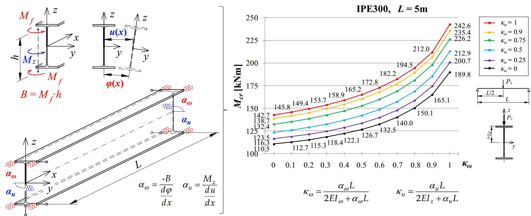
The static diagram of the beam elastically restrained against warping and against lateral rotation at the support nodes is shown in Figure 1. The springs in colour symbolically represent the elastic restraint in the support sections, i.e., in red—warping restraint (αω), and in blue—lateral rotation restraint (αu).
The degree of elastic restraint against warping εω [33,34,35] can be determined from formula:
where: αω—stiffness of the elastic restraint against warping [33,34,35] acc. formula:
where: B—bimoment at the site of beam support, ϕ—twist angle, —warping of the section.
The degree of elastic restraint εω acc. formula (1), ranges from εω = 0 for complete warping freedom to εω = ∞ for full prevention of warping.
In this study, the degree of elastic restraint against rotation in the plane of lateral torsional buckling εu, was derived. It was written in the following form:
where: αu—stiffness of the elastic restraint against lateral rotation acc. formula:
where: Mz—bending moment with respect to the minor axis of the section at the support, u—lateral deflection, —rotation about axis z.
The degree of elastic restraint εu, acc. formula (3), ranges from εu = 0 for complete rotational freedom to εu = ∞ for full prevention of rotation in the plane of lateral torsional buckling.
In order to account, in an explicit manner, for the beam elastic restraint, in the twist angle function ϕ(x) and the lateral deflection function u(x), the dimensionless indexes of fixity against warping κω [34] and against lateral rotation κu were introduced acc. formulas:
Indexes of fixity range from κω = 0 (κu = 0) for complete freedom of warping or lateral rotation, respectively, to κω = 1 (κu = 1) for complete blockage of warping or lateral rotation.
Inverse relations, i.e., αω(κω) and αu(κu), have the following form:
3. Twist Angle Function and Lateral Deflection Function
In study [42], in which lateral torsional buckling of fork-supported beams was analysed, the function of the twist angle of the section was approximated using power polynomials that described “the deflection function” of the hinged beam (Table 1, polynomials WPi). In Table 1, formulas for the polynomials of deflection were written in the dimensionless coordinates ρ = x/L. To account for the elastic restraint against warping in the beam support section, in study [34], the twist angle function (ϕ) was extended. That was done by introducing additional polynomials that describe “the deflection function” of the restrained beam (Table 1, polynomials WUi). “Hinged” polynomials (WPi) were coupled with “restrained” polynomials (WUi) by means of the index of fixity against warping κω (5a) [34] acc. formula:
where: ai—free parameters of the twist angle function, WPi, WUi—polynomials acc. Table 1.
The polynomials used (Table 1) satisfy the boundary conditions of the twist angle function for the fork support WPi (ϕ = 0, ϕ” = 0 for x = 0 and x = L), and for full restraint WUi (ϕ = 0, ϕ’ = 0 for x = 0 and x = L), respectively.
In this study, to account for the elastic restraint of the beam against lateral rotation at the support nodes, the lateral deflection function (u) was written in a way analogous to (8). Thus “hinged” polynomials (WPi) and “restrained” polynomials (WUi) were “coupled” by means of the index of fixity κu (5b) acc. formula:
where: bi—free parameters of the lateral deflection function.
The polynomials used (Table 1) satisfy the boundary conditions of the lateral deflection function for the fork support WPi (u = 0, u” = 0 for x = 0 and x = L) and for full restraint WUi (u = 0, u’ = 0 for x = 0 and x = L).
Functions (8) and (9) make it possible to model boundary conditions at the nodes for the elastic restraint against warping and against lateral rotation for arbitrary (i.e., from 0 to 1 interval) values of the indexes of fixity κω acc. (5a) and κu acc. (5b).
4. The Critical Moment for Lateral Torsional Buckling
The energy method was used to determine the critical moment (Mcr) of a single-span beam with bisymmetric I-section while taking into account elastic restraints (κω, κu) at the support nodes. The total potential energy of the beam—load system was determined from formula:
where: Us,1—elastic strain energy of beam bending and torsion; Us,2—energy of the elastic restraint against warping; Us,3—energy of the elastic restraint against lateral rotation; T—work done by external forces.
The elastic strain energy of the beam bending and torsion [10] was expressed with the equation:
The energy of the elastic restraint against warping (Us,2) [34] and against lateral rotation (Us,3) was determined from formulas:
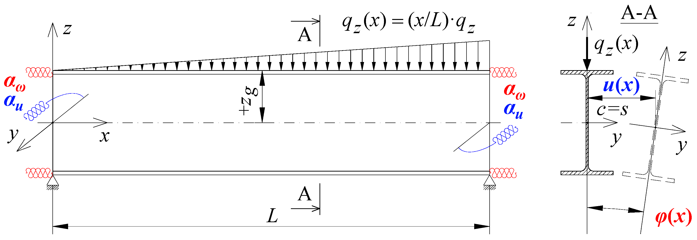
The work done by external forces is a function of the loading diagram and the co-ordinate of the point of load application. For instance, for a simply supported beam (Figure 2), loaded with linearly varied distribution of transverse load, for an arbitrary co-ordinate (zg) of the point of load application over the section height, the work done by external forces can be written as follows:
To determine Mcr, a programme for numerical computations, namely McrLT_elastic_warping_rotation_2.nb (MLTB,EL,2 for short) was developed in the environment of the Mathematica® package. The programme allows the determination of the critical load as a function of the indexes of fixity (κω, κu), for arbitrary geometric parameters of the bisymmetric I-section, an arbitrary value of the co-ordinate (zg) of the load application point (see Figure 2), for beam loading diagrams that are most commonly found in practice (Table 2; Table 3). In the programme, the first three terms (a1,2,3) of the twist angle function acc. (8) and the first three terms (b1,2,3) of the lateral deflection function acc. (9) were employed.
In study [34], McrLT_elastic_fix.on.warp._sym.cal.nb programme was developed to make symbolic “computations” for those cases, in which elastic restraint against warping (κω) occurs. In order to receive possibly simple approximation formulas, only the first term {a1((1 − κω)WP1 + κωWU1)} of the beam twist angle function (8) was employed. Still, a very good congruence between the results thus obtained and those produced by FEM (LTBeam, Abaqus) was noted.
In this study, McrLT_elastic_warping_rotation_sym.cal.nb programme was formulated, in analogous terms, in the environment of the Mathematica® package. The programme is geared towards symbolic “computations”, and it accounts for both elastic restraint against warping (κω) and against rotation in the plane of lateral torsional buckling (κu). In this case, for the loading diagrams shown in Table 2 and Table 3, the first term of the twist angle function (8) and the first or the second term {bi((1 − κu)WPi + κuWUi)}i = 1 or 2 of the lateral deflection function (9) were employed.
The formula for the critical moment for lateral torsional buckling, which addresses the indexes of fixity (κω, κu) and an arbitrary ordinate (zg) of the point of transverse load application with respect to centre of the section sheer (see Figure 2), has the following form:
where: B1, B2, B3, B4 and D1—coefficients acc. Table 2.
For loads applied at the section shear centre (zg = 0), the formula for the critical moment is reduced to the following form:
As regards the beam loaded with moments concentrated at the ends (for −1 ≤ ψ ≤ 1, Table 3), the formula for the critical moment for lateral torsional buckling, which accounts for arbitrary (0 ÷ 1) values of the indexes of fixity (κω, κu), has the following form:
where: C1, C2, C3 and D1—coefficients acc. Table 3.
Formula (16), derived for concentrated moments from the interval −0.5 < ψ ≤ 1 (see Table 3), in which symmetric or slightly asymmetric (with respect to the beam midspan) lateral torsional buckling mode occurs, was approximated with the first term of the twist angle function (8) and the first term of the lateral deflection function (9). However, for the interval −1 ≤ ψ ≤ −0.5, where much more asymmetric mode of lateral torsional buckling is found, the best results were obtained for the first term of the twist angle function (8) and the second term of the lateral deflection function (9).
The design of approximation formulas makes it possible to develop relatively simple spreadsheets.
5. FEM Verification
To verify the results of numerical calculations performed acc. MLTB,EL,2 programme and the results of analytical calculations made with approximation Formulas (14), (15) and (16), LTBeam software (FEM) [40] was used. The software allows the adoption of the classic boundary conditions i.e., fork support or complete fixity. Also, it accounts for the beam elastic restraint against the section warping and against rotation in the plane of lateral torsional buckling. As mentioned already, the LTBeam software version 1.0.11 contains an error in the units of the coefficient of the elastic restraint against warping (αω). The error results in the lowering of the actual value of αω when it is given in the commonly used unit [kNcm3/rad]. The drawback was eliminated in the LTBeamN latest version, i.e., 1.0.3.
For the sake of comparison, in checking computations, predetermined values of the indexes of fixity κω and κu were assumed. In this case, the stiffness of the elastic restraint against warping (αω) and the stiffness of the elastic restraint against lateral rotation (αu), which are necessary to make LTBeam computations were determined from Formula (6ab).
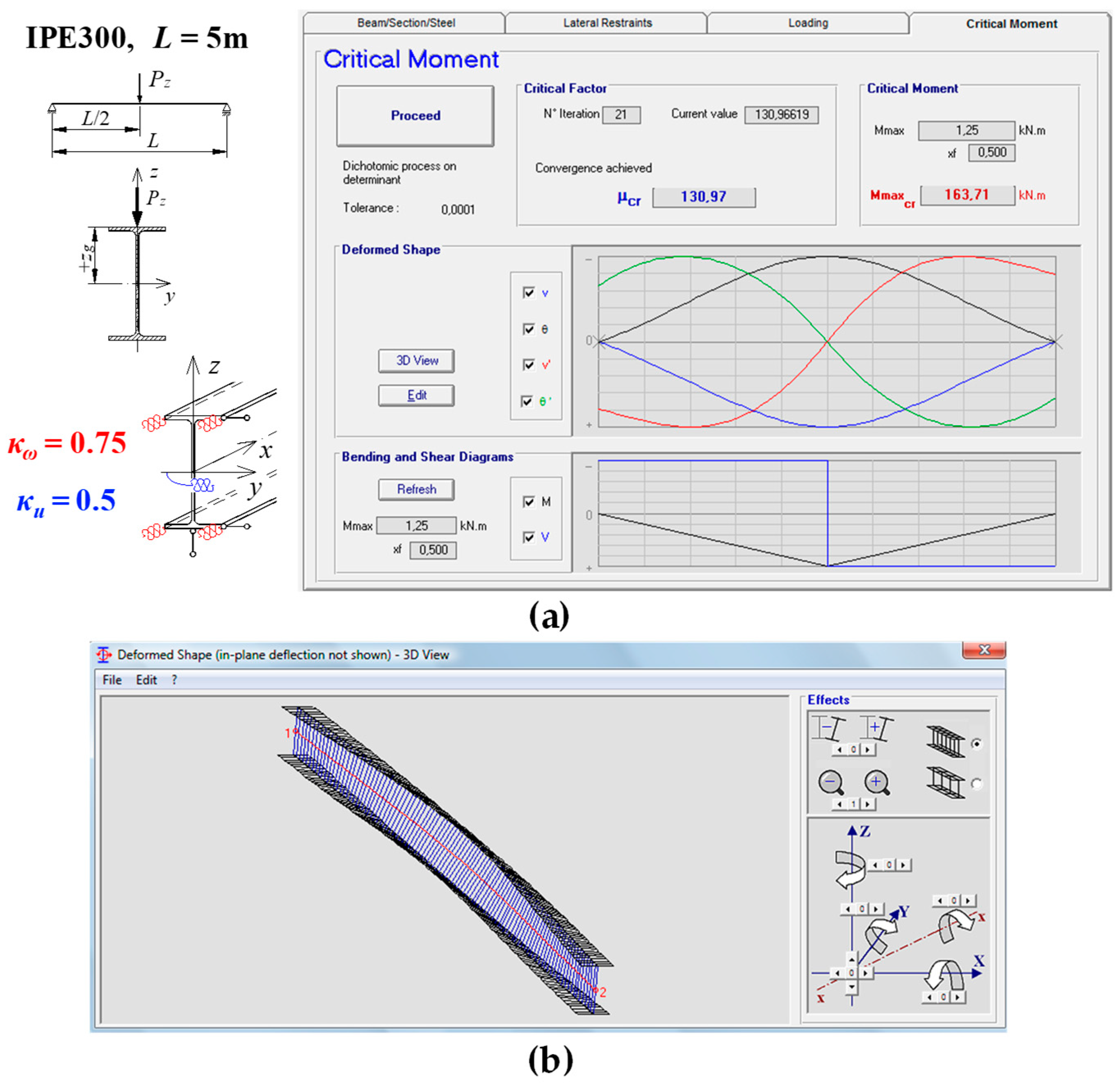
Figure 3 shows the form of lateral torsional buckling of the beam (Figure 3b) for the critical moment determined with the LTBeam programme.
An exemplary IPE300 beam, with span L = 5 m, was loaded with a concentrated force applied at the midspan to the upper flange of the beam (zg = +h/2). The elastic restraint against warping (κω = 0.75) and lateral rotation (κu = 0.5) of the beam at support nodes were taken into account. The critical moment of the lateral torsional buckling of beam was obtained, having the value of Mcr = 163.71 kNm (Figure 3a). The critical moments for beams analysed in this paper, for different types of sections, spans and load diagrams, and for different degrees of elastic restraint against warping and against lateral rotation, were determined in the way presented above. The results are discussed in Section 6.
6. Examples
To make a comparative analysis, steel beams (E = 210GPa, G = 81GPa) made from IPE300, HEA300, HEB300 sections with a span of L = 5 and 7 m, and beams fabricated from IPE500, HEA500, HEB500 sections with a span of L = 8 and 10 m were assumed. In computations, the loads were as those in the diagrams shown in Table 2 and Table 3. For the diagrams in Table 2, transverse loads were applied to the top flange (zg = +h/2), to the section weight axis (zg = 0) and to the bottom flange (zg = −h/2). When the loads were moments concentrated at supports (Table 3), the whole range of variation of the ratio of the moments (−1 ≤ ψ ≤ 1) was taken into account for the following parameter values ψ = {−1; −0.75; −0.5; −0.25; 0; 0.25; 0.5; 0.75; 1}. Analyses were carried out for the full range of variation of the index of fixity against warping κω (from 0 to 1) and against lateral rotation κu (from 0 to 1) for the following values of κi = {0; 0.25; 0.5; 0.75; 0.9; 1}. Computations were run for various combinations of the values of indexes κω and κu. For each of the beams analysed, the critical moment for lateral torsional buckling was determined acc. MLTB,EL,2 programme using 3 terms of both series (8) and (9). The critical moment was estimated with Formulas (14), (15) and (16), and then compared with the values obtained from FEM (LTBeam). As the number of received values of the critical moment of beams was large, the paper reports only selected results of detailed cases (Table 4 and Table 5, Figure 4; Figure 5). Cumulative analyses of results (for all cases included in the paper) are presented in Table 6.
Table 4 lists exemplary results of calculations obtained for IPE300 beam, with a span of L = 5 m, loaded with a concentrated force applied to the upper flange (zg = +h/2) at the midspan. Percentage differences in the results obtained with MLTB,EL,2 programme (Column 6) relative to the LTBeam programme (Column 5) are shown in Column 7. Analogous comparison of the results obtained with Formula (14) (Column 8) and the LTBeam programme (Column 5) can be seen in Column 9.
When compared with LTBeam, the critical moments determined using MLTB,EL,2 programme showed the differences of +0.6 to +1.9% (Table 4). The application of the approximation Formula (14) produced the values that differed from −3.4 to −0.5% in comparison with FEM.
Table 5 lists exemplary results of computations for IPE300 beam, L = 5 m, and selected values of indexes κω and κu, and loading diagrams acc. Table 2 and Table 3. The percentage differences in the results obtained with the MLTB,EL,2 programme (Column 7) relative to the LTBeam programme (Column 6) are shown in Column 8. Analogous comparison of the results obtained from the Formulas (14) and (16) (Column 9) and the LTBeam programme (Column 6) is given in Column 10.
In addition to the comparison of the values of Mcr, the results compiled in Table 4 and Table 5 can be employed in the tests on the correctness of the design of Formulas (14) and (16) in spreadsheets.
Table 6 lists the maximum percentage differences between the results obtained by the authors and those produced using LTBeam for beams IPE300, HEA300, HEB300, IPE500, HEA500 and HEB500.
In addition to the data shown in Table 6, it should be noted that for Scheme 1, the values received with MLTB,EL,2 programme differed from +0.5 to +2.6% (HEB300, L = 5 m), and the results obtained acc. Formula (14) showed differences of from −3.8 (IPE500, L = 10 m) to +4.1% (HEA300, L = 5 m) compared with LTBeam. As regards Scheme 2, MLTB,EL,2 program gave critical moments that differed from 0 to +0.7% (HEA500, L = 10 m), and the differences for Formula (14) were from −3.0 to +2.6% (HEA300, L = 5 m). For Scheme 3, MLTB,EL,2 programme values differed from −0.5 to +0.7% (HEB500, L = 10 m), and Formula (14) values showed differences of −2.3 to +3.3% (HEA300, L = 5 m). Finally, for Scheme 4, MLTB,EL,2 programme generated critical moments that were 0 to +4.9% (HEA300, L = 5 m) different, and acc. Formula (16), from −3.2 (HEA300, L = 5 m) to +4.0% (IPE300, L = 7 m).
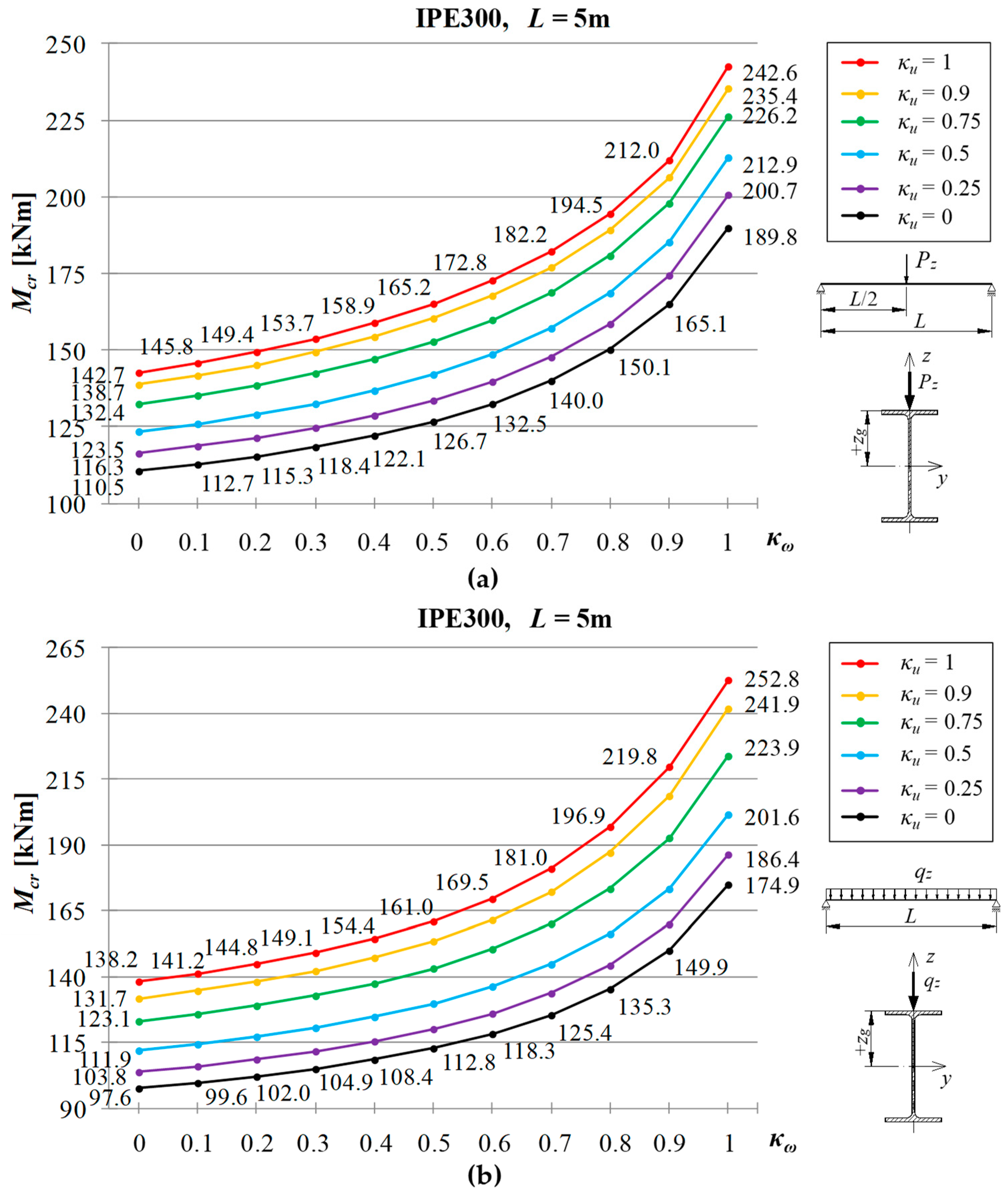
Figure 4 presents the courses of variation of Mcr for a beam made of an IPE300 profile with a span L = 5 m, depending on the value of the index of fixity against warping κω (from 0 to 1) for selected values of the index of fixity against lateral rotation κu = {0; 0.25; 0.5; 0.75; 0.9; 1}. Concentrated force load (Figure 4a) or uniformly distributed load (Figure 4b) was applied to the upper flange of the beam (zg = +h/2). Critical moments of the beam were determined with Formula (14).
The comparison of the critical moments of lateral torsional buckling (Figure 4), obtained for the full warping restraint (κω = 1) in relation to its full freedom (κω = 0), shows +71% (Figure 4a) and +81% (Figure 4b) increase in Mcr, basically regardless of the value of the κu index. The dependence Mcr(κω) is strongly non-linear throughout the whole range of the κω restraint index (from 0 to 1).
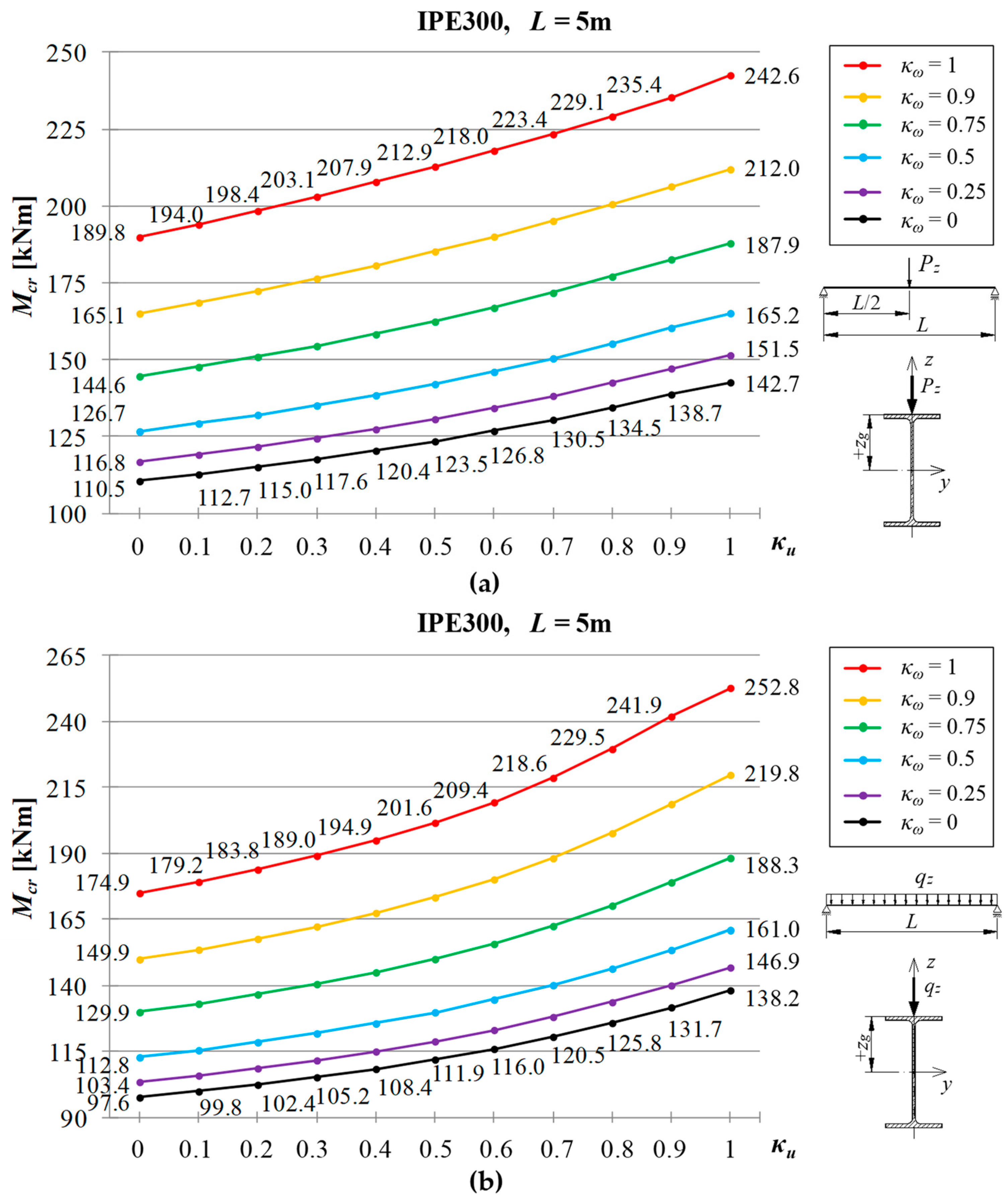
Figure 5 shows the courses of variation of critical moments of lateral torsional buckling of the beam, for geometric parameters according to Figure 4, depending on the value of the index of fixity against lateral rotation κu (from 0 to 1) for selected values of the index of fixity against warping κω = {0; 0.25; 0.5; 0.75; 0.9; 1}.
The comparison of the critical moments of lateral torsional buckling (Figure 5), obtained for the full lateral rotation restraint (κu = 1) in relation to its full freedom (κu = 0), shows +29% (Figure 5a) and +43% (Figure 5b) increase in Mcr, basically regardless of the value of the κω index. In this case, the dependence Mcr(κu) is mildly non-linear throughout the entire range of the κu restraint index (from 0 to 1).
In the case (Figure 4; Figure 5) warping and lateral rotation are fully restrained at supports (i.e., κω = κu = 1) of the IPE300 beam with the span L = 5 m, nearly +120% (Figure 4a and Figure 5a) and +159% (Figure 4b and Figure 5b) increase in the critical moment Mcr was found compared with the conditions of full freedom of warping and lateral rotation (i.e., κω = κu = 0), which correspond to fork support.
7. Conclusions
A natural trend in the development of modern design methods is to account for the factors that influence the structure bearing capacity and reliability.
When actual conditions of beam support at the nodes are well represented, critical moments can be computed more accurately. Consequently, the coefficient of lateral torsional buckling and the design resistance of the beam can also be calculated more precisely. Such an approach allows taking more informed decision regarding the structural reliability of members. Intuitive estimation of the bearing capacity reserves is substituted with objective criteria.
The comparison of the critical moments (Table 4, Table 5 and Table 6), which were determined using MLTB,EL,2 programme and estimated from Formulas (14), (15) and (16), with the values obtained from LTBeam revealed a very good congruence of the results. The critical loads were computed for: (1) different variants in the selection of the indexes of fixity (κω, κu) which changed in the interval from 0 to 1; (2) various (characteristic) points at which transverse loads were applied (top flange, weight axis of the section and bottom flange); and (3) full range of variation in the ratio of the moments concentrated at the supports (−1 ≤ ψ ≤ 1).
The results obtained by the authors indicate that the estimations of the critical moments produced with the Formulas (14), (15) and (16) derived in the study, give approximations that are sufficient from the engineering standpoint. If the formulas mentioned above are written in the spreadsheet, it is necessary to compare the results obtained with Table 4 and Table 5.
With an increase in the indexes of fixity (κω, κu), the value of the critical load of the beams grows. The critical moment for lateral torsional buckling is affected, to a greater extent, by the restraint of the support sections of the beam against warping.
Finally, in order to ensure the recommended level of structural reliability already at the design stage, it should be recommended to check computer calculations with the use of an available analytical method.
Author Contributions
Introduction was prepared by R.P. and A.S. Mathematical description was written by R.P. and A.S. Results were obtained by R.P. The analysis of the results and conclusions were written by R.P. and A.S.
Funding
Project financed under the programme of the Minister of Science and Higher Education under the name “Regional Initiative of Excellence” in the years 2019–2022 project number 025/RID/2018/19 amount of financing 12 000 000 PLN.
Conflicts of Interest
The authors declare no conflict of interest.
References
- Szychowski, A. A theoretical analysis of the local buckling in thin-walled bars with open cross-section subjected to warping torsion. Thin-Walled Struct. 2014, 76, 42–55. [Google Scholar] [CrossRef]
- Bijak, R. Critical Moment for Lateral Torsional Buckling of Unbraced Bisymmetric I-Beams with Fork Support; XII ICMS Wrocław: Wrocław, Poland, 2011; pp. 144–151. (In Polish) [Google Scholar]
- Lim, N.H.; Park, N.H.; Kang, Y.J.; Sung, I.H. Elastic buckling of I-beams under linear moment gradient. Int. J. Soldis Struct. 2003, 40, 5635–5647. [Google Scholar] [CrossRef]
- López, A.; Yong, D.J.; Serna, M.A. Lateral-torsional buckling of steel beams: A general expression for the moment gradient factor. In Proceedings of the Stability and Ductility of Steel Structures, Lisbon, Portugal, 6–8 September 2006. [Google Scholar]
- Mohri, F.; Damil, N.; Potier-Ferry, M. Linear and non-linear stability analyses of thin-walled beams with monosymmetric I sections. Thin-Walled Struct. 2010, 48, 299–315. [Google Scholar] [CrossRef]
- Serna, M.A.; López, A.; Puente, I.; Yong, D.J. Equivalent uniform moment factors for lateral-torsional buckling of steel members. J. Constr. Steel Res. 2006, 62, 566–580. [Google Scholar] [CrossRef]
- Trahair, N.S.; Bradford, M.A.; Nethercot, D.A.; Gardner, L. The Behavior and Design of Steel Structures to EC3, 4th ed.; Taylor & Francis: London, UK; New York, NY, USA, 2008. [Google Scholar]
- Bijak, R. The lateral buckling of simply supported unrestrained bisymmetric I-shape beams. Arch. Civ. Eng. 2015, LXI, 127–140. [Google Scholar] [CrossRef]
- Mohri, F.; Brouki, A.; Roth, J.C. Theoretical and numerical stability analyses of unrestrained, mono symmetric thin-walled beams. J. Constr. Steel Res. 2003, 59, 63–90. [Google Scholar] [CrossRef]
- Timoshenko, S.P.; Gere, J.M. Theory of Elastic Stability; Arkady: Warszawa, Poland, 1963. (In Polish) [Google Scholar]
- Weiss, S.; Giżejowski, M. Stability of Metal Structures. Rod Systems; Arkady: Warszawa, Poland, 1991. (In Polish) [Google Scholar]
- Bijak, R. The lateral buckling of steel I-shape beams with continuous torsional elastic restraints. Bud. I Archit. Lub. Krynica 2013, 12, 181–188. (In Polish) [Google Scholar]
- Larue, B.; Khelil, A.; Gueury, M. Elastic flexural-torsional buckling of steel beams with rigid and continuous lateral restraints. J. Constr. Steel Res. 2007, 63, 692–708. [Google Scholar] [CrossRef]
- Lindner, J. Influence of constructional details on the load carrying capacity of beams. Eng. Struct. 1996, 18, 752–758. [Google Scholar] [CrossRef]
- Szymczak, C. Sensitivity analysis of thin-walled members, problems and applications. Thin-Walled Struct. 2003, 41, 271–290. [Google Scholar] [CrossRef]
- Valentino, J.; Trahair, N.S. Torsional restraint against elastic lateral buckling. J. Struct. Eng. 1998, 124, 1217–1225. [Google Scholar] [CrossRef]
- Yura, J. Fundamentals of beam bracing. Eng. J. 2001, First Quarter, 11–26. [Google Scholar]
- Bijak, R.; Brzezińska, K. Reduction In The Critical Moment for Lateral Torsional Buckling of Coped Beams. Appl. Mech. Mater. 2015, 797, 3–10. [Google Scholar] [CrossRef]
- Giżejowski, M. Lateral buckling of steel beams with limited rotation ability at supports. Inżynieria I Bud. 2001, 57, 589–594. (In Polish) [Google Scholar]
- Johnston, G.; Driver, R.G.; Callele, L. Behaviour and Stability of Double-coped Beam-to-girder Connections under Combined Loading. In Proceedings of the Annual Stability Conference, Structural Stability Research Council, Toronto, ON, Canada, 25–28 March 2014. [Google Scholar]
- Maljaars, J.; Stark, J.W.B.; Steenbergen, H.M.G.M. Buckling of coped steel beams and steel beams with partial endplates. HERON 2004, 49, 233–271. [Google Scholar]
- Maljaars, J.; Stark, J.W.B.; Steenbergen, H.M.G.M.; Abspoel, R. Lateral–torsional buckling resistance of coped beams. J. Constr. Steel Res. 2005, 61, 1559–1575. [Google Scholar] [CrossRef]
- Maljaars, J.; Stark, J.W.B.; Steenbergen, H.M.G.M.; Abspoel, R. Development and validation of a numerical model for buckling of coped beams. J. Constr. Steel Res. 2005, 61, 1576–1593. [Google Scholar] [CrossRef]
- Gosowski, B. Non-uniform torsion of stiffened open thin-walled members of steel structures. J. Constr. Steel Res. 2007, 63, 849–865. [Google Scholar] [CrossRef]
- Gosowski, B.; Redecki, M. Lateral-torsional buckling moments for I-beams with local lateral restraints. Inżynieria I Bud. 2012, 68, 140–144. (In Polish) [Google Scholar]
- Lee, H.E.; Nguyen, C.T.; Moon, J.H.; Joo, H.S. Lateral-torsional buckling of discretely-braced i-girder. Procedia Eng. 2011, 14, 264–271. [Google Scholar] [CrossRef]
- Stroetmann, R. Lateral torsional and distortional buckling of cross-connected beams. In Proceedings of the Eighth International Conference on Advances in Steel Structures, Lisbon, Portugal, 22–24 July 2015. [Google Scholar]
- Kowal, Z.; Malec, M. Critical resistance of beams with support ribs with closed section. Inżynieria I Bud. 1989, 2, 71–74. (In Polish) [Google Scholar]
- Kurzawa, Z.; Rzeszut, K.; Szumigała, M.; Chybiński, M. The influence of frontal plates on the load-carrying capacity of beams in bending. Inżynieria I Bud. 2006, 62, 163–166. (In Polish) [Google Scholar]
- Lindner, J.; Gietzelt, R. Stabilisierung von Biegeträgern mit I-Profil durch angeschweiβte Kopfplatten. Stahlbau 1984, 3, 69–74. [Google Scholar]
- Masarira, A. The effect of joints on the stability behaviour of steel frame beams. J. Constr. Steel Res. 2002, 58, 1375–1390. [Google Scholar] [CrossRef]
- Pałkowski, S. Lateral torsional buckling of I-beams with end plates. Inżynieria I Bud. 1997, 8, 394–395. (In Polish) [Google Scholar]
- Pi, Y.-L.; Trahair, N.S. Distortion and warping at beam supports. J. Struct. Eng. 2000, 126, 1279–1287. [Google Scholar] [CrossRef]
- Piotrowski, R.; Szychowski, A. Lateral-torsional buckling of beams elastically restrained against warping at supports. Arch. Civ. Eng. 2015, LXI, 155–174. [Google Scholar] [CrossRef]
- Gotluru, B.P.; Schafer, B.W.; Pekoz, T. Torsion in thin-walled cold-formed steel beams. Thin-Walled Struct. 2000, 37, 127–145. [Google Scholar] [CrossRef]
- Živner, T.J. The influence of constructional detail to lateral-torsional buckling of beams. Procedia Eng. 2012, 40, 504–509. [Google Scholar] [CrossRef]
- Piotrowski, R.; Szychowski, A. Impact of support closed section ribs on the critical moment for lateral torsional buckling of steel beams. Struct. Environ. 2018, 10, 5–18. [Google Scholar] [CrossRef]
- Szychowski, A. Stability of the Compressed Box Girder Chord at Longitudinal Stress Variation; XII ICMS Wrocław: Wrocław, Poland, 2011; pp. 202–211. (In Polish) [Google Scholar]
- Szychowski, A. Local stability of the compressed flange of a cold-formed thin-walled section. ZNPRz 2011, 276, 307–314. (In Polish) [Google Scholar]
- Galéa, Y. Moment critique de déversement élastique de poutres fléchies. Présentation du logiciel LTBEAM. Revue Construction Métallique. CTICM 2003, 2. Available online: https://www.cticm.com/centre-de-ressources/ (accessed on 20 April 2019).
- Szychowski, A. Stability of cantilever walls of steel thin-walled bars with open cross-section. Thin-Walled Struct. 2015, 94, 348–358. [Google Scholar] [CrossRef]
- Piotrowski, R.; Szychowski, A. Applying the Energy Method and Polynomials to the Determination of the Critical Buckling Moments in Beams; Konstr. Betonowe I Met. Bydg.: Krynica, Poland, 2015; pp. 249–257. (In Polish) [Google Scholar]
- Jakubowski, S. Buckling of Thin-Walled Girders under Compound Load. Thin-Walled Struct. 1988, 6, 129–150. [Google Scholar] [CrossRef]
Figure 1.
Static diagram of the beam: (a) bimoment (B) and moment (Mz) at the support, (b) elastic restraint against warping (αω) and against lateral rotation (αu), (c) twist angle ϕ(x) and lateral deflection u(x).
Figure 1.
Static diagram of the beam: (a) bimoment (B) and moment (Mz) at the support, (b) elastic restraint against warping (αω) and against lateral rotation (αu), (c) twist angle ϕ(x) and lateral deflection u(x).

Figure 2.
Exemplary diagram of beam loading. qz(x)—function of transverse load.

Figure 3.
Exemplary beam modeled using the LTBeam software: (a) the critical moment for lateral torsional buckling of beam, (b) deformed shape of beam.
Figure 3.
Exemplary beam modeled using the LTBeam software: (a) the critical moment for lateral torsional buckling of beam, (b) deformed shape of beam.

Figure 4.
The critical moment of lateral torsional buckling of beam as a function of the index of fixity κω, for selected index of fixity κu: (a) beam with concentrated force load, (b) beam with uniformly distributed load.
Figure 4.
The critical moment of lateral torsional buckling of beam as a function of the index of fixity κω, for selected index of fixity κu: (a) beam with concentrated force load, (b) beam with uniformly distributed load.

Figure 5.
The critical moment of lateral torsional buckling of beam as a function of the index of fixity κu, for selected index of fixity κω: (a) beam with concentrated force load, (b) beam with uniformly distributed load.
Figure 5.
The critical moment of lateral torsional buckling of beam as a function of the index of fixity κu, for selected index of fixity κω: (a) beam with concentrated force load, (b) beam with uniformly distributed load.


| Item | Polynomials | Physical Interpretation |
|---|---|---|
| 1 | 2 | 3 |
| 1 |  | |
| 2 |  | |
| 3 |  | |
| 4 |  | |
| 5 |  | |
| 6 |  |
Table 2.
Coefficients B1, B2, B3, B4 and D1 for selected diagrams of transverse load.
| Item | Load Diagram | Coefficients |
|---|---|---|
| 1 | 2 | 3 |
| 1 |  | |
| ; | ||
| auxiliary coefficients: | ||
| ; | ||
| 2 |  | |
| ; | ||
| auxiliary coefficients: | ||
| ; | ||
| 3 |  | |
| ; | ||
| auxiliary coefficients: | ||
| ; | ||
Table 3.
Coefficients C1, C2, C3 and D1 for the beam loaded with moments concentrated at supports.
| Item | Load Diagram | Coefficients |
|---|---|---|
| 1 | 2 | 3 |
| 1 |  | |
| auxiliary coefficients: | ||
| ; | ||
| ; | ||
| ; | ||
| ; | ||
 | ||
| auxiliary coefficients: | ||
| ; | ||
| ; | ||
| ; | ||
| ; |
Table 4.
Comparison of Mcr for beam IPE300 (L = 5 m).
| Item | Load Diagram | κω | κu | Mcr [kNm] | ||||
|---|---|---|---|---|---|---|---|---|
| LTBeam | MLTB,EL,2 | % 6-5 | Formula (14) | % 8-5 | ||||
| 1 | 2 | 3 | 4 | 5 | 6 | 7 | 8 | 9 |
| 1 |  IPE300 L = 5 m zg = +h/2 | 0 | 0 | 111.2 | 111.9 | 0.6 | 110.5 | −0.6 |
| 2 | 0.25 | 117.2 | 118.0 | 0.7 | 116.3 | −0.8 | ||
| 3 | 0.5 | 124.4 | 125.4 | 0.8 | 123.5 | −0.7 | ||
| 4 | 0.75 | 133.4 | 134.6 | 0.9 | 132.4 | −0.7 | ||
| 5 | 0.9 | 140.1 | 141.5 | 1.0 | 138.7 | −1.0 | ||
| 6 | 1 | 145.1 | 146.8 | 1.2 | 142.7 | −1.7 | ||
| 7 | 0.25 | 0 | 117.5 | 118.2 | 0.6 | 116.8 | −0.6 | |
| 8 | 0.25 | 123.9 | 124.8 | 0.7 | 123.0 | −0.7 | ||
| 9 | 0.5 | 131.6 | 132.7 | 0.8 | 130.7 | −0.7 | ||
| 10 | 0.75 | 141.3 | 142.6 | 0.9 | 140.4 | −0.6 | ||
| 11 | 0.9 | 148.3 | 149.9 | 1.1 | 147.2 | −0.7 | ||
| 12 | 1 | 153.8 | 155.6 | 1.2 | 151.5 | −1.5 | ||
| 13 | 0.5 | 0 | 127.4 | 128.3 | 0.7 | 126.7 | −0.5 | |
| 14 | 0.25 | 134.5 | 135.5 | 0.7 | 133.6 | −0.7 | ||
| 15 | 0.5 | 143.0 | 144.2 | 0.8 | 142.1 | −0.6 | ||
| 16 | 0.75 | 153.6 | 155.1 | 1.0 | 152.8 | −0.5 | ||
| 17 | 0.9 | 161.4 | 163.2 | 1.1 | 160.4 | −0.6 | ||
| 18 | 1 | 167.4 | 169.4 | 1.2 | 165.2 | −1.3 | ||
| 19 | 0.75 | 0 | 145.7 | 146.9 | 0.8 | 144.6 | −0.8 | |
| 20 | 0.25 | 153.9 | 155.2 | 0.8 | 152.7 | −0.8 | ||
| 21 | 0.5 | 163.7 | 165.3 | 1.0 | 162.4 | −0.8 | ||
| 22 | 0.75 | 176.0 | 177.9 | 1.1 | 174.4 | −0.9 | ||
| 23 | 0.9 | 185.0 | 187.4 | 1.3 | 182.7 | −1.2 | ||
| 24 | 1 | 191.9 | 194.6 | 1.4 | 187.9 | −2.1 | ||
| 25 | 0.9 | 0 | 166.8 | 168.4 | 1.0 | 165.1 | −1.0 | |
| 26 | 0.25 | 176.1 | 177.9 | 1.0 | 174.4 | −1.0 | ||
| 27 | 0.5 | 187.4 | 189.5 | 1.1 | 185.3 | −1.1 | ||
| 28 | 0.75 | 201.3 | 203.9 | 1.3 | 197.9 | −1.7 | ||
| 29 | 0.9 | 211.5 | 214.7 | 1.5 | 206.4 | −2.4 | ||
| 30 | 1 | 219.4 | 222.9 | 1.6 | 212.0 | −3.4 | ||
| 31 | 1 | 0 | 191.8 | 194.0 | 1.1 | 189.8 | −1.0 | |
| 32 | 0.25 | 202.3 | 204.9 | 1.3 | 200.7 | −0.8 | ||
| 33 | 0.5 | 215.0 | 217.9 | 1.3 | 212.9 | −1.0 | ||
| 34 | 0.75 | 230.5 | 234.1 | 1.6 | 226.2 | −1.9 | ||
| 35 | 0.9 | 241.9 | 246.1 | 1.7 | 235.4 | −2.7 | ||
| 36 | 1 | 250.5 | 255.3 | 1.9 | 242.6 | −3.2 | ||
Table 5.
Comparison of Mcr for beam IPE300 (L = 5 m).
| Item | Load Diagram | κω | κu | ψ | Mcr [kNm] | ||||
|---|---|---|---|---|---|---|---|---|---|
| LTBeam | MLTB,EL,2 | % 7-6 | Formula (14), (16) | % 9-6 | |||||
| 1 | 2 | 3 | 4 | 5 | 6 | 7 | 8 | 9 | 10 |
| 1 |  IPE300 L = 5 m zg = +h/2 | 1 | 0 | − | 177.2 | 177.4 | 0.1 | 174.9 | −1.3 |
| 2 | 0.9 | 0.25 | − | 163.1 | 163.1 | 0.0 | 159.9 | −1.9 | |
| 3 | 0.75 | 0.5 | − | 152.8 | 152.8 | 0.0 | 150.0 | −1.8 | |
| 4 | 0.5 | 0.75 | − | 145.7 | 145.7 | 0.0 | 143.2 | −1.7 | |
| 5 | 0.25 | 0.9 | − | 142.8 | 142.9 | 0.1 | 140.0 | −1.9 | |
| 6 | 0 | 1 | − | 141.6 | 141.6 | 0.0 | 138.2 | −2.4 | |
| 7 |  IPE300 L = 5 m zg = +h/2 | 1 | 0 | − | 180.6 | 181.1 | 0.3 | 179.7 | −0.5 |
| 8 | 0.9 | 0.25 | − | 165.9 | 166.4 | 0.3 | 164.0 | −1.1 | |
| 9 | 0.75 | 0.5 | − | 155.2 | 155.9 | 0.4 | 153.6 | −1.0 | |
| 10 | 0.5 | 0.75 | − | 147.7 | 148.6 | 0.6 | 146.4 | −0.9 | |
| 11 | 0.25 | 0.9 | − | 144.8 | 145.7 | 0.7 | 143.1 | −1.1 | |
| 12 | 0 | 1 | − | 143.5 | 144.4 | 0.6 | 141.1 | −1.7 | |
| 13 |  IPE300 L = 5 m Formula (16) | 1 | 0 | −1 | 622.6 | 641.0 | 3.0 | 624.7 | 0.3 |
| 14 | 0.9 | 0.25 | −0.75 | 534.1 | 539.8 | 1.1 | 535.6 | 0.3 | |
| 15 | 0.75 | 0.5 | −0.5 | 454.8 | 457.4 | 0.6 | 456.1 | 0.3 | |
| 16 | 0.5 | 0.75 | −0.25 | 419.7 | 422.0 | 0.5 | 424.7 | 1.2 | |
| 17 | 0.25 | 0.9 | 0 | 407.8 | 410.3 | 0.6 | 407.0 | −0.2 | |
| 18 | 0 | 1 | 0.25 | 399.3 | 401.2 | 0.5 | 394.5 | −1.2 | |
| 19 | 0.5 | 0.5 | 0.5 | 222.2 | 222.3 | 0.0 | 221.1 | −0.5 | |
| 20 | 0.75 | 0.75 | 0.75 | 259.3 | 259.4 | 0.1 | 259.7 | 0.2 | |
| 21 | 1 | 1 | 1 | 342.4 | 342.5 | 0.1 | 347.2 | 1.4 | |
Table 6.
Percentage differences in the values of Mcr for all analysed beams.
| Item | Load Diagram | MLTB,EL,2 vs. LTBeam | Formulas (14), (15) vs. LTBeam | Formula (16) vs. LTBeam |
|---|---|---|---|---|
| 1 | 2 | 3 | 4 | 5 |
| 1 |  | from +0.5 to +2.6% | from −3.8 to +4.1% | − |
| 2 |  | from 0 to +0.7% | from −3.0 to +2.6% | − |
| 3 |  | from −0.5 to +0.7% | from −2.3 to +3.3% | − |
| 4 |  | from 0 to +4.9% | − | from −3.2 to +4.0% |
© 2019 by the authors. Licensee MDPI, Basel, Switzerland. This article is an open access article distributed under the terms and conditions of the Creative Commons Attribution (CC BY) license (http://creativecommons.org/licenses/by/4.0/).
Share and Cite
MDPI and ACS Style
Piotrowski, R.; Szychowski, A. Lateral Torsional Buckling of Steel Beams Elastically Restrained at the Support Nodes. Appl. Sci. 2019, 9, 1944. https://doi.org/10.3390/app9091944
AMA Style
Piotrowski R, Szychowski A. Lateral Torsional Buckling of Steel Beams Elastically Restrained at the Support Nodes. Applied Sciences. 2019; 9(9):1944. https://doi.org/10.3390/app9091944
Chicago/Turabian StylePiotrowski, Rafał, and Andrzej Szychowski. 2019. "Lateral Torsional Buckling of Steel Beams Elastically Restrained at the Support Nodes" Applied Sciences 9, no. 9: 1944. https://doi.org/10.3390/app9091944
Note that from the first issue of 2016, this journal uses article numbers instead of page numbers. See further details here.