A Comparison Study of a Novel Self-Contained Electro-Hydraulic Cylinder versus a Conventional Valve-Controlled Actuator—Part 1: Motion Control


Department of Engineering Sciences, University of Agder, 4879 Grimstad, Norway
*
Author to whom correspondence should be addressed.
Actuators 2019, 8(4), 79; https://doi.org/10.3390/act8040079
Submission received: 30 October 2019
/
Revised: 18 November 2019
/
Accepted: 3 December 2019
/
Published: 5 December 2019
(This article belongs to the Special Issue Electro-Hydraulic Actuators)
Abstract
:This research paper presents the first part of a comparative analysis of a novel self-contained electro-hydraulic cylinder with passive load-holding capability against a state of the art, valve-controlled actuation system that is typically used in load-carrying applications. The study is carried out on a single-boom crane with focus on the control design and motion performance analysis. First, a model-based design approach is carried out to derive the control parameters for both actuation systems using experimentally validated models. The linear analysis shows that the new drive system has higher gain margin, allowing a considerably more aggressive closed-loop position controller. Several benefits were experimentally confirmed, such as faster rise time, 75% shorter settling time, 61% less overshoot, 66% better position tracking, and reduction of pressure oscillations. The proposed control algorithm is also proven to be robust against load variation providing essentially the same position accuracy. In conclusion, the novel self-contained system is experimentally proven to be a valid alternative to conventional hydraulics for applications where passive load-holding is required.
1. Introduction
Compact and self-contained electro-hydraulic cylinders (SCCs) have received considerable attention in the last decade [1,2,3,4,5,6,7,8,9]. They are, according to the definition used in this paper, self-sufficient linear hydraulic actuators controlled by a dedicated hydraulic unit that is driven by an electric prime mover. A sealed tank is essential and additional components, such as flow balancing valves, are required when using single-rod cylinders that are preferred in many applications due to the excellent force density. Furthermore, SCCs have shown the potential to replace both conventional hydraulics as well as linear electro-mechanical systems in low-power applications (i.e., below 5 kW) enhancing energy efficiency, modular design, plug-and-play installation, and reduced maintenance [1]. Current commercial solutions of the SCC technology are limited and typically tailor-made [8], especially the ones developed for load-carrying applications that are required to contain passive load-holding devices, according to the safety regulations (e.g., ISO 17096 and DNVGL-ST-0378). Then, the research emphasis is primarily on different electro-hydraulic configurations [10,11,12,13], for low-power servo applications [14,15,16,17]. There is, therefore, a lack of experimental studies comparing state-of-the-art, valve-controlled technology for load-carrying applications to self-contained hydraulic cylinders in the technical literature, both in terms of motion performance and energy efficiency. Hence, the first part of this research aims to experimentally assess the motion performance of a novel self-contained electro-hydraulic cylinder against a conventional valve-controlled approach (as a side note, the second part of this study [18] focuses on the energy efficiency). This goal is achieved by modeling the SCC (Section 2), recalling the valve-controlled cylinder (Section 3), and designing a suitable control algorithm (Section 4). Finally, the comparison between the two architectures is given, in terms of motion performance, in Section 5. A single-boom crane built explicitly for having a flexible structure of the boom that induces pressure oscillations is chosen as case-study since it represents a worst-case scenario within load-carrying applications typically used in an offshore environment. The comparison study will show that the novel self-contained system is a valid alternative to conventional hydraulics for applications where passive load-holding is required in combination with precise position tracking in harsh environments.
2. The Self-Contained Electro-Hydraulic Cylinder
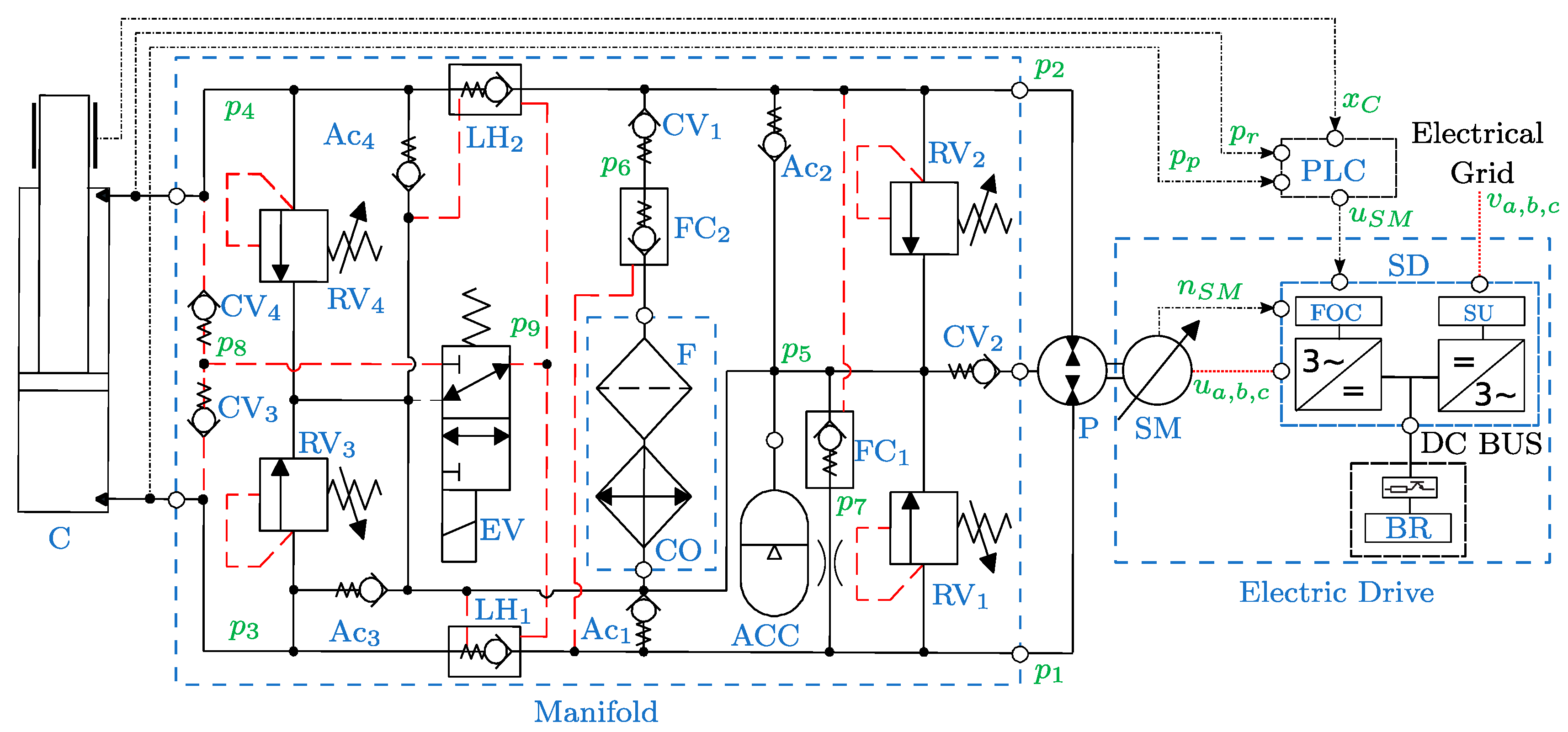
The combination of an electric drive and a fixed-displacement axial piston machine (P) drives the hydraulic cylinder (C) arranged in a closed-circuit configuration, as illustrated in Figure 1.
The auxiliary hydraulic components are implemented in a manifold, and the bladder-type accumulator (ACC) represents the sealed reservoir. The differential flow dictated by the cylinder’s unequal areas is balanced by the two pilot-operated check valves FC1 and FC2, the check valves Ac1 and Ac2, and the check valve CV1. The pilot-operated check valves LH1 and LH2 are used for passive load-holding purposes by isolating the cylinder when the 3/2 electro-valve (EV) is not actuated. The EV must be activated to enable the actuator motion, resulting in transferring the highest cylinder pressure, selected through the CV3 and CV4, into the opening pilot line of LH1 and LH2. Anti-cavitation valves (Ac3 and Ac4) are installed between the actuator sides and the ACC to avoid cavitation in the cylinder chambers. Pressure-relief valves (RV1–RV4) on both pump ports and on both cylinder ports avoid over-pressurizations. Finally, a cooler (CO) and a low-pressure filter (F) complete the hydraulics.
The electric drive consists of two main components, namely the servo-motor (SM) and the servo-drive (SD). The supply unit (SU) of the driver converts the AC voltage from the electrical grid to a DC bus voltage. The DC bus voltage is further shared with the PWM inverter, controlling the speed of the prime mover based on the field-oriented controller (FOC). A closed-loop position controller is implemented on the programmable logic controller (PLC) controlling the motion of the hydraulic cylinder by sending the control signal (i.e., the desired rotational speed of the prime mover) to the variable speed controller embedded in the servo-drive. An external brake resistor (BR) is connected to the DC bus to dissipate the regenerated power as heat.
2.1. Nonlinear Model of the System
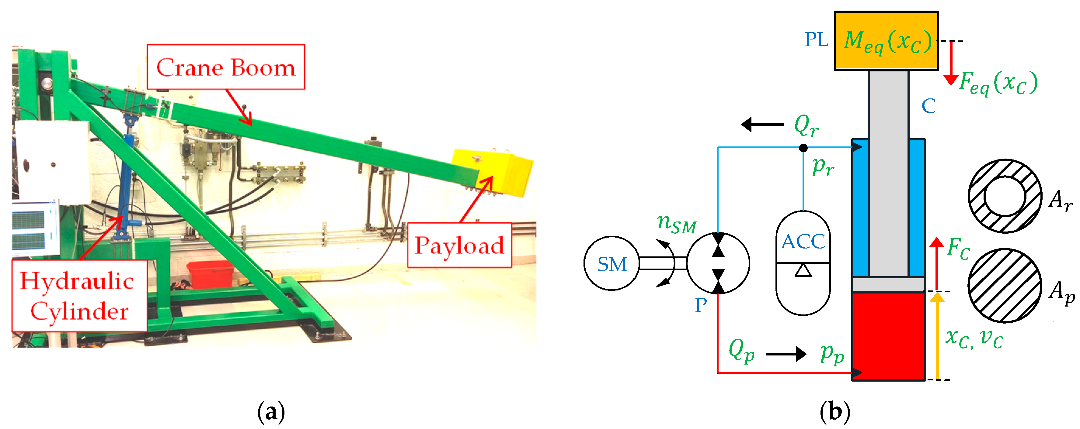
A high-fidelity, dynamic model of the considered SCC driving the single-boom crane depicted in Figure 2a is presented and validated in [9]. This paper introduces the simplified system model that is used for linear control design. All models are created, simulated, and analyzed in MATLAB-Simulink®. Since the SCC used in this application only operates in two quadrants, the rod-side chamber is always connected to the low-pressure accumulator as visible in Figure 2b. (It is assumed that the 3/2 electro-valve is energized to enable motion).
The nonlinear model of the simplified mechanical-hydraulic system is described using the Newton’s second law to extract the actuator dynamics:
This equation is based on the equivalent mass () and on the equivalent gravitational force () of the single-boom crane. Their trends were derived in Padovani et al. [9] as a function of the piston position (). The mechanical force delivered by the hydraulic cylinder:
involves the piston-side area (), the piston chamber pressure (), the rod-side area (), the rod chamber pressure (), the viscous friction coefficient (), and the piston velocity (). The well-known pressure buildup equations for the dynamics of the actuator pressures result as:
They include the effective pump flow (), the internal leakage in the cylinder (), the piston-side capacitance (), and the rod-side capacitance () specified below:
The effective pump flow in Equation (5) is based on the pump displacement (), on the angular speed of the servo-motor (), and on the pump’s flow losses (), as explained in [9]. It should be noted that a positive sign of the motor speed denotes operations in pumping mode (i.e., throughout piston extension), whereas a negative sign refers to motoring mode (i.e., during piston retraction). The two capacitances in Equations (6) and (7) include the effective volume of the actuator chambers ( represents the maximum stroke length of the cylinder), the transmission lines’ volumes (), and the bulk modulus of the hydraulic fluid () assumed constant. The rod-side capacitance also accounts the hydro-pneumatic accumulator by recalling the effective accumulator gas volume (), the pre-charge pressure of the accumulator (), and the adiabatic air constant ().
2.2. Linear Model of the System
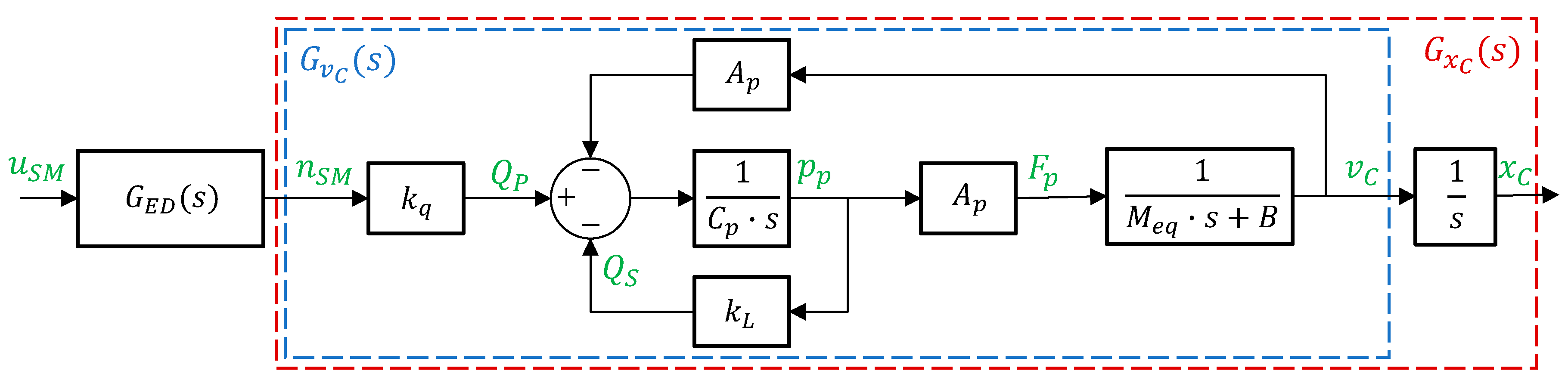
The simplified model of the SCC has been linearized and is now investigated when its natural-frequency is low (i.e., when the hydraulic cylinder is extended) because it limits the performance and represents the worst-case scenario. The resulting block diagram illustrated in Figure 3 has been obtained by considering the capacitance and the equivalent mass constant and calculated with the piston almost fully extended ( m). Additionally, the rod-side pressure is assumed constant and equal to bar due to its extremely low value [9], while the external force has been considered as a disturbance that is not included in the linear model.
The transfer function of the electric drive from commanded speed () to actual speed () is described by the following open-loop, second-order transfer function including the natural-frequency () and the damping ratio ():
The velocity output of the uncompensated mechanical-hydraulic system is described by the second-order, open-loop transfer function using the gain (), the natural-frequency (), and the damping ratio () according to the equations below:
These parameters are evaluated using the pump flow gain ( )), and the leakage flow gain () that includes both the internal leakage in the hydraulic cylinder and the flow losses mentioned in Equation (5). Finally, the transfer function from the servo-motor speed to piston position is derived by integrating .
The numerical values representative of the system and details about their identification are shared in Appendix A.
3. The Valve-Controlled System
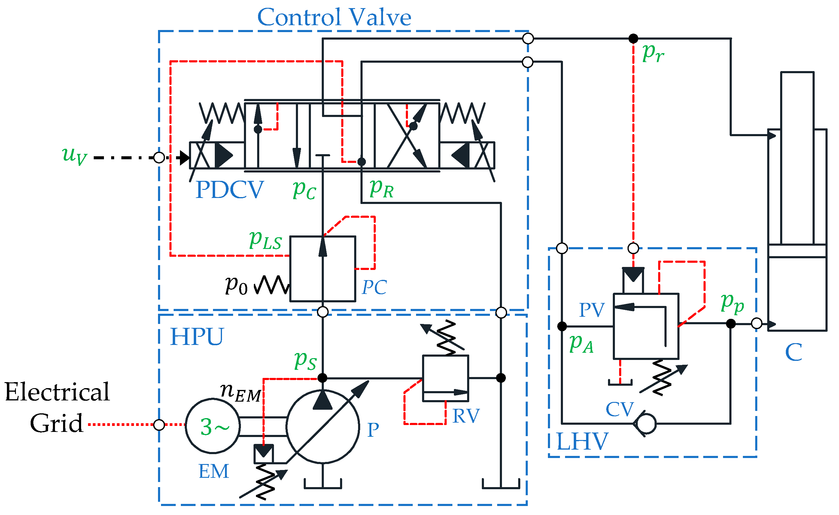
The hydraulic, valve-controlled drive taken into account as the benchmark is used in several industrial applications, such as offshore cranes and oil drilling equipment, and represents the state of the art (e.g., [19,20,21,22]). The system consists of a centralized hydraulic power unit (HPU) providing a constant supply pressure () and a fixed return pressure () to the valve-controlled cylinder, as illustrated in Figure 4.
The components of the HPU are the electric motor (EM) running at constant speed and the variable-displacement axial piston pump (P). The supply pressure is controlled by the absolute pressure limiter, while a pressure-relief valve (RV) is installed for safety.
The motion of the hydraulic cylinder is controlled by a pressure-compensated, proportional directional control valve (PDCV) that receives the control input from the embedded controller. The state-of-the-art flow control valve consists of two essential parts, namely the main spool with integrated closed-loop position control and the pressure compensator (PC) that guarantees a load-independent pressure drop across the metering edge. The load-holding valve (LHV), namely a vented counterbalance valve with a pilot ratio 3:1, contains a by-pass check valve (CV) and a pilot-operated poppet valve (PV) for controlling overrunning loads (i.e., when retracting the cylinder). Finally, the system is instrumented with sensors for measuring the pressures labeled in Figure 4 as well as the rod-side flow rate () and the piston’s position.
4. The Control Design
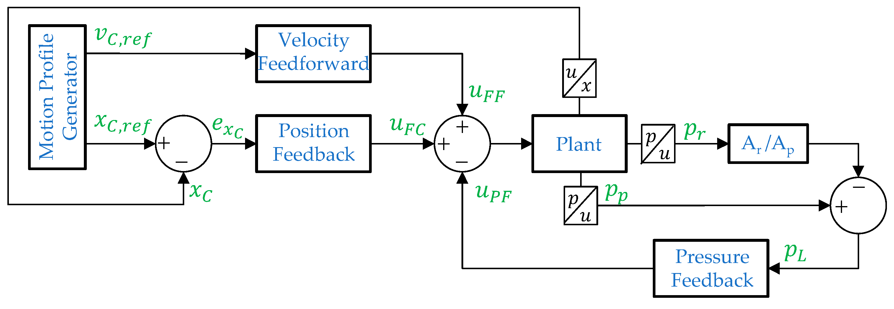
To have a fair comparison between the considered SCC and the VCC, a common control strategy based on a closed-loop PI position controller in combination with a velocity feedforward and a pressure feedback is implemented according to Figure 5.
The pressure feedback represents the active-damping term of the hydraulic system that is essential due to the extremely low damping ratio of the uncompensated system (). Hence, the pressure feedback’s parameters are first chosen so that the desired damping ratio of the system is obtained before designing the motion controller for the damped system; a complete explanation of the process used to derive these parameters is included in Appendix B. Further on, the motion profile generator presented in [19] provides reference signals for the desired piston velocity () and piston position () to the motion controller. The motion controller consists of the combination of two blocks, namely the velocity feedforward and the position feedback. The summation of the feedforward signal (), position feedback signal (), and pressure feedback signal () represents the desired control input. For the SCC, this input represents the desired rotational speed of the servo-motor (), while it represents the desired valve opening () in the VCC. Based on the piston area, the pump flow gain, and the reference velocity of the piston, the desired speed of the prime mover is calculated as:
The control signal from the position feedback is given as:
where the proportional gain () and the integral gain () are derived in the following equations:
and the gain margin (Gm) and the phase cross over frequency () are explained in the next sections.
In addition, the VCC’s control algorithm compensates for the overlap in the valve’s spool according to [20], while the SCC can be operated using two different load-holding strategies. Passive load-holding (PLH) (i.e., running the prime mover is not desired during load-holding phases) takes place when the load-holding valves are closed by deactivating the electro-valve signal:
and by switching off the signal enabling power to the electric motor according to the logic below:
Conversely, active load-holding (ALH) is performed by controlling the desired piston position using the prime mover (i.e., the load-holding valves are kept open).
4.1. Control Parameters for the Self-Contained Electro-Hydraulic Cylinder
The proportional and integral gains are derived using the Bode plots according to the procedure proposed in [23]. As explained in this reference, the PI-controller should lead to fast response and only to a small overshoot if the phase margin is chosen around a phase angle of . In order to ensure a stable closed-loop controller, the proportional gain in Equation (15) is calculated using the gain margin that corresponds to the phase crossover frequency at which the phase angle of the open-loop transfer function is equal to ). The identified parameters from the Bode plots and the resulting PI-controller gains are presented in Table 1 for both the uncompensated system () and the solution that includes the high-pass filtered pressure feedback ().
Pressure feedback adds artificial damping and increases the gain margin that allows significant higher PI-controller gains while still ensuring a stable system. The approach with a high-pass filtered pressure feedback is selected, where a model-based approach for selecting the gain /) and the time constant s of the filter is used (a complete explanation of the process used to derive these quantities is included in Appendix B.2). This feedback is implemented in the control algorithm illustrated in Figure 5 as:
4.2. Control Parameters for the Valve-Controlled System
A linear state-space model of the considered VCC was used in Hagen et al. [20] to derive the high-pass filtered pressure feedback parameters. As demonstrated in this reference, additional damping is necessary to achieve smooth operations since the combination of a pressure-compensated control valve and a counterbalance valve makes the system unstable both in open- and closed-loop control, when the load is overrunning. The high-pass filter’s parameters were evaluated as /) and . Lastly, the Bode plots of the compensated open-loop system presented in [20] are used to identify the gain margin and the phase cross over frequency. This is a necessary step to derive the PI-controller gains in Table 2 that are based on Equations (15) and (16).
5. Results and Discussion
Three closed-loop tests are carried out to analyze the motion performance of the novel self-contained system compared to the valve-controlled solution. Details about the considered test setups are explained in the second part of this study [18]. First, a step response is performed with maximum payload (i.e., load mass equal to kg) to evaluate the closed-loop response time. Then, a working cycle with maximum payload and different piston velocity setpoints is performed to assess the tracking error. Finally, the single-boom crane is also actuated with half payload and without payload to explore the actuation system’s robustness against load variations.
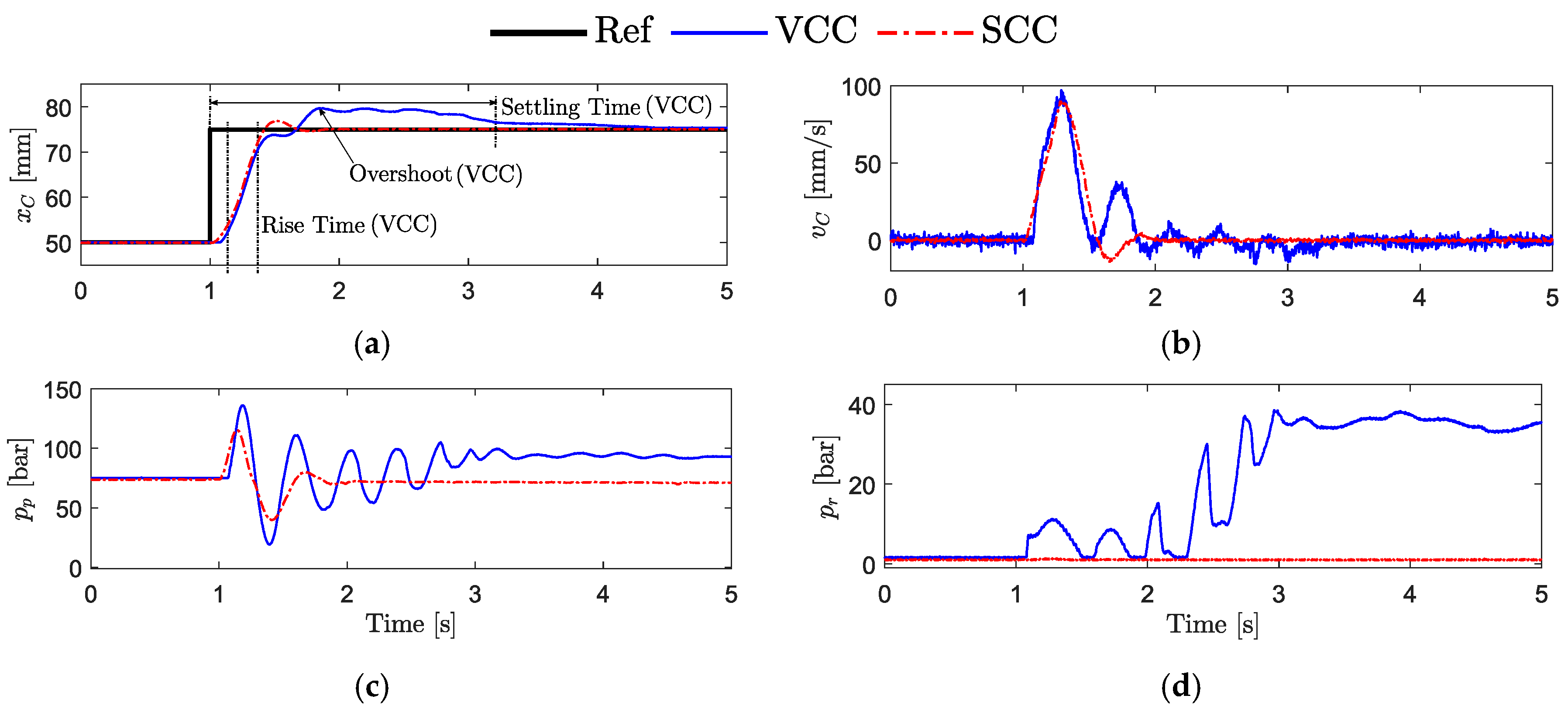
5.1. Closed-Loop Step Response
The closed-loop step response of both systems is reported in Figure 6. A relatively small position step from 50 to 75 mm is commanded to avoid flow saturation of the control valve in the VCC. The resulting piston velocity remains within the limits (Figure 6b) since its maximum values are 120 mm/s for the VCC and about 170 mm/s for the SCC.
The SCC has 10 ms faster rise time, % faster settling time (i.e., the time required by the velocity error to fall within 2% of the reference value), and % less overshoot than the VCC (Table 3 provides the exact values). The response of the VCC is expected to be slower because the open-loop crossover frequency of the compensated system is 2.25 rad/s lower than that of the SCC. As seen in Figure 6c, the piston-side chamber’s pressure of the VCC has more oscillations and higher spikes than the SCC. This pressure in the VCC is about 22 bar higher at steady-state than the SCC; it is the case because the rod-side chamber’s pressure (Figure 6d) is about 38 bar higher when compared to the SCC that maintains a stable pressure of about 1.0 bar.
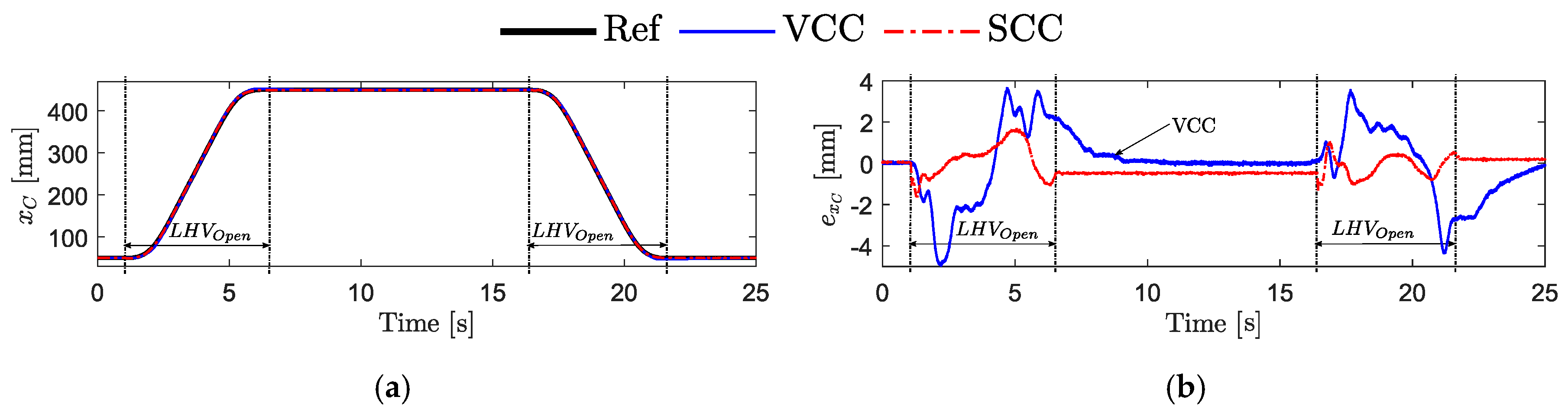
5.2. Representative Working Cycle
Based on the maximum flow that the two systems can deliver to the cylinder, the highest desired piston velocity () is assumed equal to 120 mm/s, and the SCC is operated with passive load-holding in the following tests. A motion profile generator is used at different velocity setpoints equal to 20, 75, and 120 mm/s, starting from the initial piston position mm to the final position mm. Figure 7 shows the position tracking performance of both systems at mm/s, also indicating when the load-holding valves of the SCC are engaged/disengaged.
Both systems can follow the desired motion profile satisfactorily, even though the maximum tracking error results are 5.0 mm for the VCC and only 1.7 mm for the SCC (i.e., 66% less). During passive load-holding, it can be seen that the VCC reaches approximately zero steady-state error. The SCC closes, however, the load-holding valves and switches off the electric motor when the measured position error is within mm, resulting in a steady-state error of about −0.48 mm. The piston position is maintained constant until the load-holding valves are opened again (i.e., at about 16.5 s). The resulting RMS tracking errors for the different velocities’ setpoints are presented in Table 4; it is concluded that the SCC behaves significantly more precisely when medium/high velocity is desired.
Figure 8 illustrates the commanded and measured control inputs of both systems.
The measured control signals follow the commanded values fairly well during motion. The measured speed of the servo-motor (Figure 8a) matches the desired one with high accuracy; when the load-holding valves are closing, at about 6.7 and 21.8 s, there is a limited spike due to the drop of the piston-side pump’s pressure. The control valve (Figure 8b) has an expected positive overlap in the spool (i.e., a dead-band) between −11.5 and +14.3% of the opening that is compensated by the motion controller; this is the reason for the, apparently, oscillatory behavior.
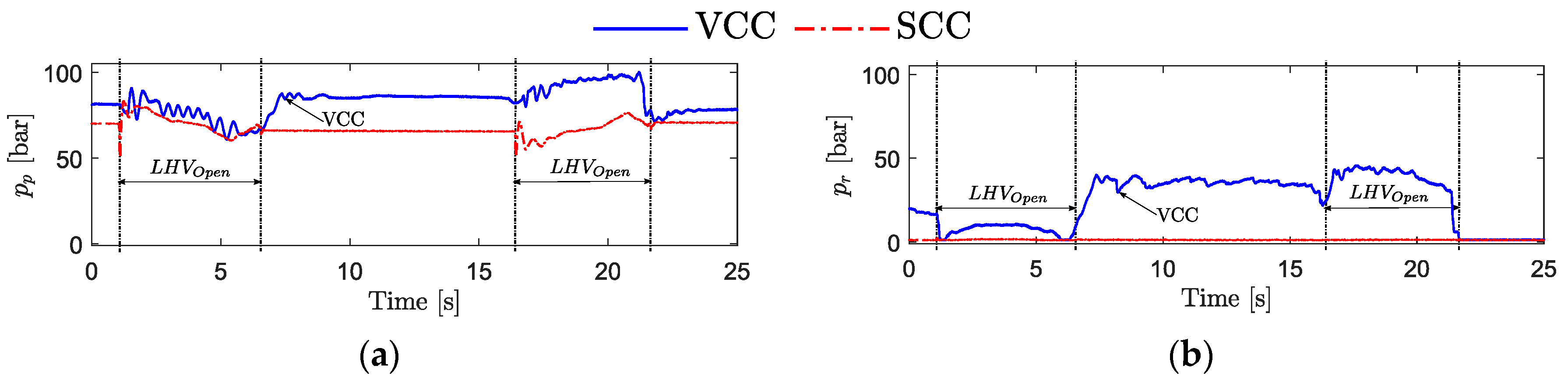
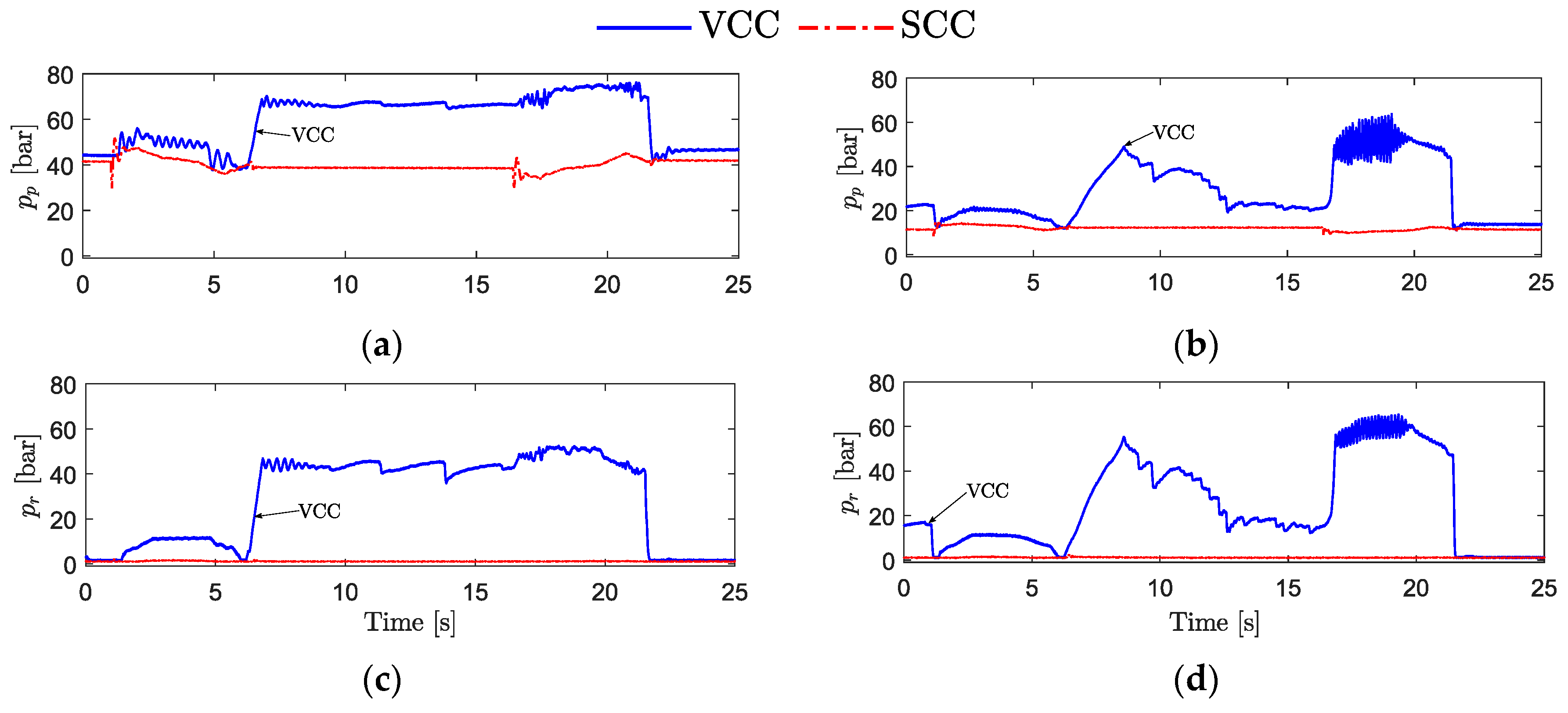
Figure 9 provides the actuator pressures of both systems.
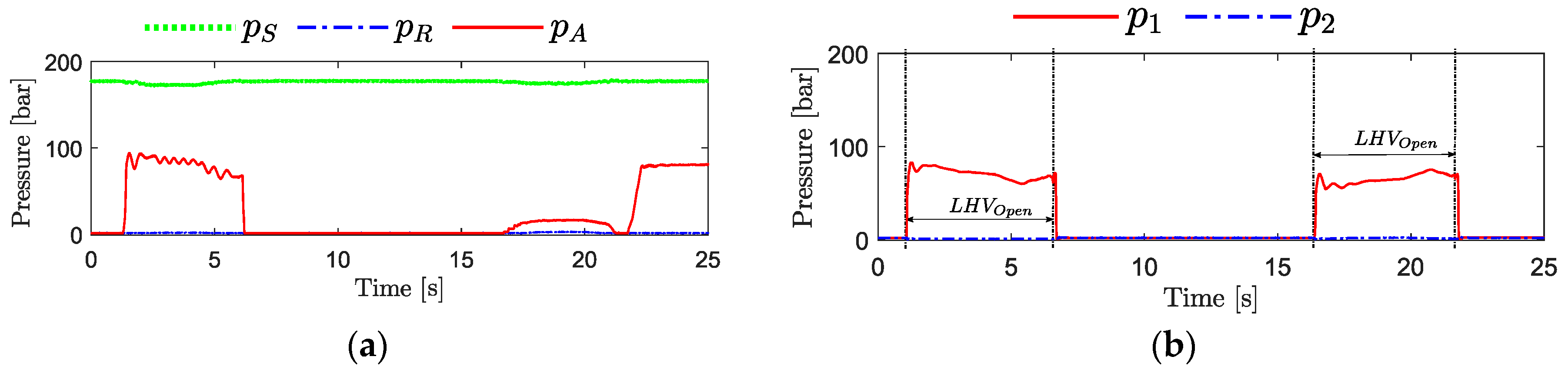
The VCC has a higher piston-side chamber’s pressure (Figure 9a) during the entire working cycle because the rod-side chamber’s pressure is higher compared to the SCC (Figure 9b). When the cylinder is lowering the crane boom (i.e., between 16.5 and 22 s), the rod-side chamber’s pressure is above 40 bar for the VCC, while it is stable and around 1 bar in the SCC. This condition is the case since the VCC solution needs to build up pressure on the rod-side to open the counterbalance valve and enable motion, while the SCC uses the load pressure taken from the piston-side to maintain the two load-holding valves fully open. In the VCC (Figure 10a), there is a constant supply pressure of 180 bar controlled by the HPU’s pump during the entire working cycle, while the pump pressures are about 1 bar for the SCC (Figure 10b) when motion is not desired.
Consequently, the SCC has the potential to be more energy-efficient during the entire working cycle compared to the VCC, where the HPU continuously consumes power.
5.3. Scenarios with Reduced Payload
Both systems are also tested with different payloads at the velocity setpoint mm/s to verify if the respective control algorithms are robust against load variations. The results of the tracking errors are shown in Figure 11 whereas the actuator pressures in Figure 12 for the load cases with half payload (i.e., load mass equal to 152 kg) and without payload, respectively.
Both systems can track the commanded piston position with similar performance as for the test at maximum payload. Hence, it is proven that the closed-loop position controllers of both systems are robust enough against load variations. The SCC has less tracking error in both load conditions, confirming the above-mentioned advantages. The VCC has higher tracking error with half payload and less tracking error without payload compared to the test with full payload. The resulting RMS tracking errors are listed in Table 5.
The maximum actuator pressures of both systems are clearly lower in magnitude compared to the tests with maximum payload (Figure 9) due to the decreased force acting on the hydraulic cylinder when reducing the payload. Nevertheless, there are disturbing pressure oscillations in the VCC without payload when lowering the crane boom (Figure 12b,d). This is the case because the bandwidth of the control valve (4.77 Hz) becomes lower than the frequency of the pressure oscillations (8.0 Hz); the natural-frequency of the mechanical-hydraulic system increases when the effective mass is reduced causing, therefore, these issues.
In general, the SCC performs better than the VCC for the considered working cycles. The SCC has faster response (i.e., shorter rise time and settling time) and less tracking error than the VCC. The increased performance is mainly because the SCC has a higher gain margin that allows a more aggressive closed-loop position controller while still ensuring a stable system. The active damping performs better (i.e., it gives a better reduction of the pressure oscillations) in the SCC compared to the VCC. The latter characteristic is motivated by the bandwidth of the SCC’s prime mover (up to 87.54 Hz for small input commands) that is 95% higher than that of the VCC’s control valve. Finally, the tests also demonstrate that the SCC can safely maintain the piston position when motion is not desired, even in case of a power shutdown. Concerning the engagement of the load-holding valves, there is a reduced pressure spike in the piston-side chamber when the load-holding is commanded. The effect, visible in Figure 9a, results in a position drop up to 1.7 mm that is considered acceptable.
6. Conclusions
This research paper presents both a theoretical and experimental analysis of a novel self-contained electro-hydraulic cylinder with particular focus on motion performance when driving a single-boom crane. A valve-controlled cylinder was used as a benchmark since it is representative of the state of the art in many fields of industry. A control algorithm was designed based on linear techniques, including pressure feedback to add artificial damping to the system. The experimental results prove that the essential passive load-holding function of the self-contained, electro-hydraulic cylinder (SCC) can safely maintain the piston position when motion is not desired. The proposed control algorithm also seems to be robust against load variation. Further on, the SCC outperforms the benchmark system when driving the single-boom crane on all fronts:
- The SCC achieves significantly better position tracking (up to 66% less tracking error and 61% less overshoot) and faster response (i.e., 10 ms faster rise time and 75% faster settling time);
- The active pressure feedback in the SCC reduces the pressure oscillations more effectively since the electric drive has about 95% higher bandwidth than the control valve.
It is therefore concluded that the novel self-contained system represents a valid alternative to conventional hydraulic systems in terms of motion performance in load-carrying applications where position tracking and reduced oscillations are essential. It is also the case when considering energy efficiency, as presented in a separate paper (i.e., the second part of this study). Lastly, emphasis for future developments will be placed on obtaining a perfectly smooth engagement/disengagement of the passive load-holding functionality.
Author Contributions
Conceptualization, D.H. and D.P.; methodology, D.H.; software, D.H.; validation, D.H.; formal analysis, D.H.; investigation, D.H.; data curation, D.H.; writing—original draft preparation, D.H.; writing—review and editing, D.H., D.P. and M.C; visualization, D.H.; supervision, D.P. and M.C.
Funding
This research was funded by the Norwegian Research Council, SFI Offshore Mechatronics, project 237896.
Conflicts of Interest
The authors declare no conflict of interest.
Nomenclature
| Abbreviations | |
| AC | Alternating current |
| ACC | Accumulator |
| Ac | Anti-cavitation valve |
| ALH | Active load-holding |
| AV | Auxiliary valves |
| BR | Brake resistor |
| C | Hydraulic cylinder |
| CO | Oil cooler |
| CV | Check valve |
| DC | Direct current |
| ED | Electric drive |
| EM | Electric motor |
| EV | Electro-valve |
| F | Low pressure oil filter |
| FC | Flow compensation valve |
| FOC | Field-oriented control |
| Gm | Gain margin |
| HPU | Hydraulic power unit |
| HS | Hydraulic system |
| LHV | Load-holding valve |
| P | Axial piston machine (pump) |
| PC | Pressure compensator |
| PDCV | Proportional directional control valve |
| PI | Proportional and integral |
| PLC | Programmable logic controller |
| PLH | Passive load-holding |
| PV | Poppet valve |
| PWM | Pulse-width modulation |
| RMS | Root mean square |
| RV | Pressure-relief valve |
| SBC | Single-boom crane |
| SCC | Self-contained electro-hydraulic cylinder |
| SD | Servo-drive |
| SM | Servo-motor |
| SU | Supply unit |
| V | Control valve |
| VCC | Valve-controlled cylinder |
| Symbols | |
| Cylinder area on the piston-side | |
| Cylinder area on the rod-side | |
| Viscous friction coefficient | |
| Piston-side capacitance | |
| Rod-side capacitance | |
| Pump displacement | |
| Actuator’s piston position error | |
| Gain of the mechanical-hydraulic system including direct pressure feedback | |
| Gain of the direct pressure feedback | |
| Gain of the high-pass filtered pressure feedback | |
| Gain of the uncompensated mechanical-hydraulic system | |
| Combined leakage flow gain | |
| Integral controller gain | |
| Pump flow gain | |
| Proportional controller gain | |
| Equivalent mass | |
| Rotational speed of the servo-motor in revolutions per minute | |
| Internal leakage in the hydraulic cylinder | |
| Actuator’s flow demand | |
| Effective pump flow | |
| Rod-side flow | |
| Pump’s flow losses | |
| Fixed pressure-drop across the proportional directional control valve | |
| Piston-side pump pressure | |
| Rod-side pump pressure | |
| Pre-charge pressure of the accumulator | |
| Load-sensing pressure | |
| Actuator’s piston chamber pressure | |
| Actuator’s rod chamber pressure | |
| Return pressure | |
| Supply pressure | |
| On/off command to enable power to the servo-motor | |
| On/off command to open or close the 3/2 electro-valve | |
| Position feedback control signal | |
| Velocity feedforward control signal | |
| Pressure feedback control signal | |
| Commanded servo-motor speed | |
| Commanded opening of the control valve’s spool position | |
| Effective accumulator gas volume | |
| Actuator’s piston velocity | |
| Actuator’s piston velocity reference command | |
| Transmission lines’ volumes between the pump and the piston-side chamber | |
| Transmission lines’ volumes between the pump and the rod-side chamber | |
| Actuator’s piston position | |
| Actuator’s initial piston position | |
| Actuator’s piston position reference command | |
| Greek symbols | |
| Constant bulk modulus of the hydraulic fluid | |
| Adiabatic air constant | |
| Time constant of the high-pass filtered pressure feedback | |
| Phase angle | |
| Gain cross over frequency | |
| Natural-frequency of mechanical-hydraulic system including direct pressure feedback | |
| Natural-frequency of the electric drive | |
| Natural-frequency of the uncompensated mechanical-hydraulic system | |
| Phase cross over frequency | |
| Angular velocity of the servo-motor in radians per second | |
| Damping ratio of the mechanical-hydraulic system including direct pressure feedback | |
| Damping ratio of the electric drive | |
| Damping ratio of the uncompensated mechanical-hydraulic system | |
| Damping ratio of the complex conjugate pole pair in the transfer function | |
Appendix A
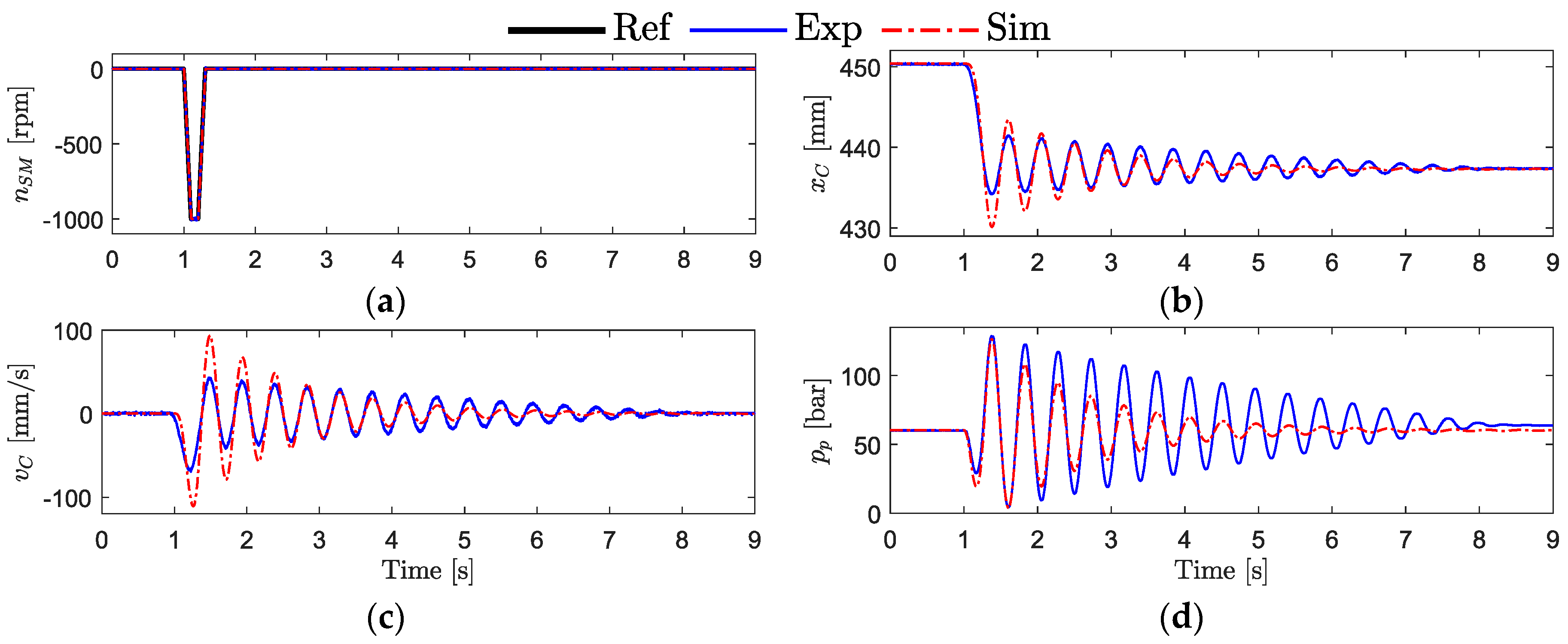
This appendix presents the parameter identification and validation of the uncompensated SCC. An open-loop ramp test was carried out, where a ramp time of 0.1 s was used to avoid saturation of the acceleration limiter of the electric drive. Figure A1 shows the given input signal and the corresponding simulated and experimental measurements. The simplified system model was validated when the hydraulic cylinder is almost fully extended (i.e., mm).
Figure A1.
Open-loop validation of the linear system model: (a) commanded, simulated, and measured speed of the servo-motor; (b) simulated and measured piston position; (c) simulated and estimated piston velocity; and (d) simulated and measured piston chamber pressure.
Figure A1.
Open-loop validation of the linear system model: (a) commanded, simulated, and measured speed of the servo-motor; (b) simulated and measured piston position; (c) simulated and estimated piston velocity; and (d) simulated and measured piston chamber pressure.

The parameters of the linear transfer functions presented in Table A1 are identified by performing a three-step parameter tuning process such that the simulated and measured values in Figure A1 best match each other. First, the natural-frequency and the damping ratio of the electric drive are tuned according to Figure A1a. Secondly, the initial volume, the bulk modulus, and the leakage flow gain are tuned according to Figure A1d. Finally, the pump flow gain is tuned according to Figure A1b.

Table A1.
Identified parameters of the transfer functions.
| Parameter | Value | Parameter | Value |
|---|---|---|---|
| / | |||
Appendix B
This appendix clarifies the definition of the control parameters involved in the pressure feedback of the SCC. Two methods were investigated in this paper to enable active damping, namely direct and high-pass filtered pressure feedback.
Figure A2 illustrates the modified plant model, where the effect of the internal pressure feedback is considered as an equivalent flow rate ().
Figure A2.
A function block representing the modified plant model that includes the pressure feedback.
Figure A2.
A function block representing the modified plant model that includes the pressure feedback.

Appendix B.1. Direct Pressure Feedback
When applying direct pressure feedback, the transfer function consists of a simple gain According to [24], should be selected so that the damping ratio of the system is within the range The open-loop transfer function from servo-motor speed to piston velocity when including direct pressure feedback is given as:
where the resulting gain (), the natural-frequency (), and the damping ratio () are:
By rewriting Equation (A4), the desired damping ratio of dictates the following pressure feedback gain:
Finally, the transfer function from servo-motor speed to piston position, including the direct pressure feedback, is derived by integrating .
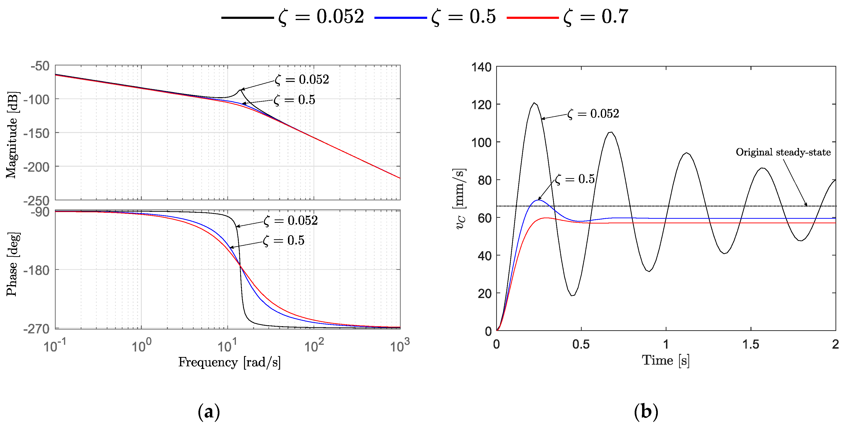
Figure A3 demonstrates the effect of applying direct pressure feedback with the desired damping of 0.5 and 0.7, in comparison to the uncompensated system with the damping ratio 0.052.
Figure A3.
The effect of different damping ratios in comparison to the uncompensated system: (a) Bode plots of and ; (b) step response ( rpm) of and .
Figure A3.
The effect of different damping ratios in comparison to the uncompensated system: (a) Bode plots of and ; (b) step response ( rpm) of and .

The control design values such as the gain margin, the cross over frequency, the rise time, the settling time, and the overshoot identified from Figure A3 are presented in Table A2 for different system’s damping ratios.
Table A2.
Identified control design values when using direct pressure feedback.
| Gm (dB) | (rad/s) | Rise Time (s) | Settling Time (s) | Overshoot (mm/s) | |
| 14.0 | 0.077 | 5.39 | 85.02 | ||
| 108 | 14.7 | 0.11 | 0.55 | 16.29 | |
| 111 | 15.0 | 0.14 | 0.40 | 4.59 |
A drawback when implementing direct pressure feedback is that the measured pressure in steady state will yield a signal that commands the prime mover to rotate. Consequently, the steady-state pressure must continuously be updated and subtracted from the measured pressures; this is also the case when implementing a low-pass filtered pressure feedback. Due to the high nonlinearities of the hydraulic system, the load that is changing during the operating cycle, and the noise of the pressure feedback signal, direct pressure feedback is challenging to implement. Hence, a high-pass filter is often used to avoid these problems [25,26]. However, direct pressure feedback is much simpler to use for linear control analysis because a second-order transfer function of the mechanical-hydraulic system is maintained. Therefore, this paper proposes to derive the pressure feedback gain according to Equation (A5) based on the desired damping ratio of the damped second-order system and further use it in the high-pass filtered pressure feedback. A damping ratio was chosen because of the faster rise time, resulting in /).
Appendix B.2. High-Pass Filtered Pressure Feedback
A high-pass filtered pressure feedback was successfully implemented on a SCC in [9] but the filter parameters where experimentally tuned. In this paper, it is proposed a model-based approach for selecting the gain () and the time constant () of the high-pass filter given below:
The open-loop transfer function from motor speed to piston velocity when including high-pass filtered pressure feedback results as:
where the different terms that form the denominator are given as follows:
Finally, the transfer function from servo-motor speed to piston position, including the high-pass filtered pressure feedback, is derived by integrating .
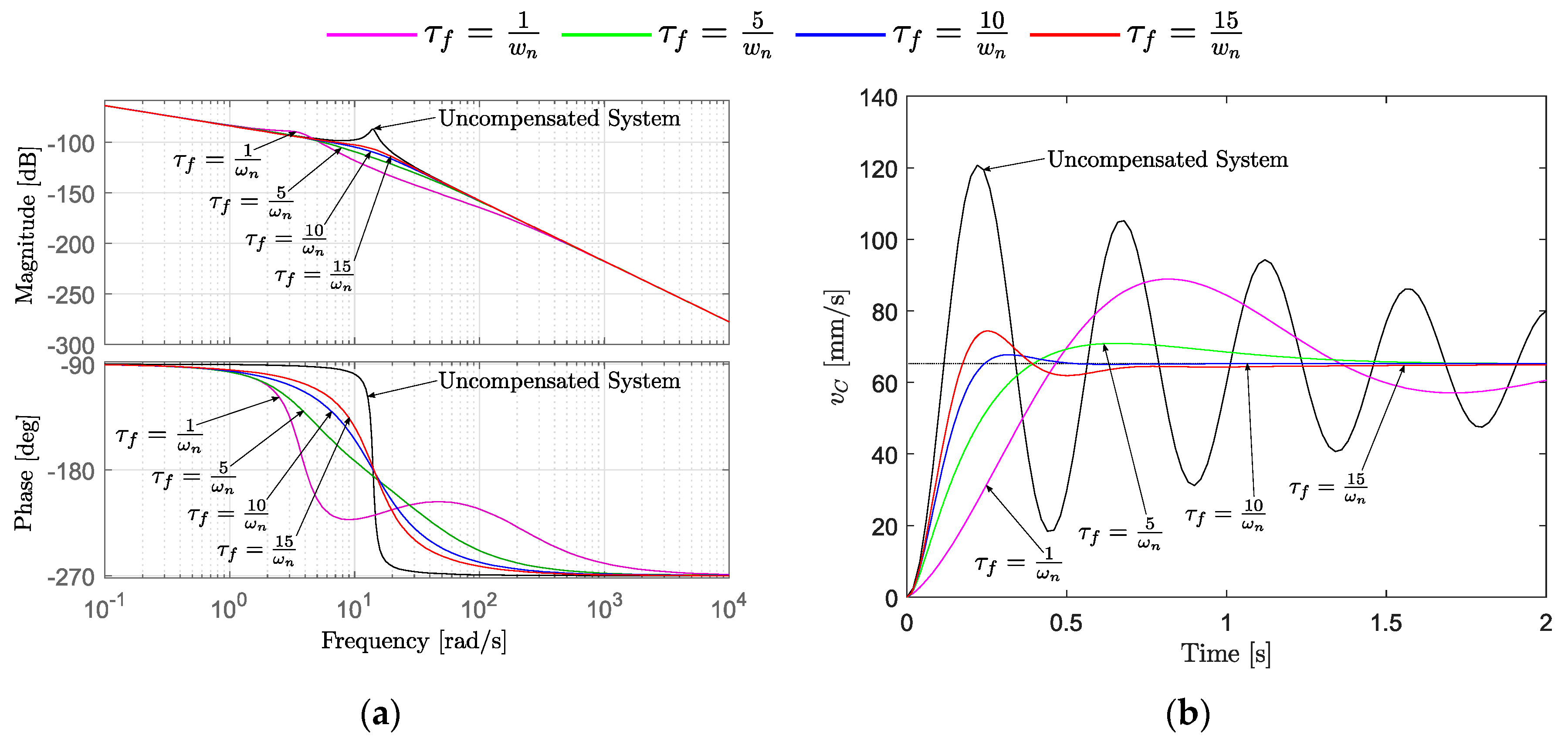
Figure A4 demonstrates the effect of varying the filter’s time constant while maintaining the same gain.
Figure A4.
The effect of varying the time constant of the high-pass filter: (a) Bode plots of and ; (b) step response of and .
Figure A4.
The effect of varying the time constant of the high-pass filter: (a) Bode plots of and ; (b) step response of and .

The control design values, namely the gain margin, the cross over frequency, the damping of the complex conjugate pole pair () of , the rise time, settling time, and the overshoot, identified from Figure A4 are presented in Table A3 for the different filter’s time constants.
Table A3.
Identified control design values when using high-pass filtered pressure feedback.
| Gm (dB) | (rad/s) | Rise Time (s) | Settling Time (s) | Overshoot (mm/s) | ||
|---|---|---|---|---|---|---|
| 4.06 | 0.319 | 0.34 | 2.93 | 36.14 | ||
| 113 | 12.2 | 0.864 | 0.27 | 1.27 | 8.61 | |
| 110 | 14.1 | 0.713 | 0.16 | 0.41 | 3.72 | |
| 107 | 14.3 | 0.486 | 0.12 | 0.67 | 13.99 |
The filter time constant s is selected because it corresponds to a damping ratio of the complex conjugate poles with a rise time comparable to the system with direct pressure feedback as demonstrated in Figure A3 and Table A1. The high-pass filtered pressure feedback causes slower rise time and settling time. However, the overshoot is 14% smaller, and the steady-state error, as shown in Figure A3b, is removed.
References
- Michel, S.; Weber, J. Electrohydraulic Compact-drives for Low Power Applications considering Energy-efficiency and High Inertial Loads. In Proceedings of the 7th FPNI PhD Symposium on Fluid Power, Reggio Emilia, Italy, 27–30 June 2012; pp. 27–30. [Google Scholar]
- Minav, T.A.; Sainio, P.; Pietola, M. Direct Driven Hydraulic Drive without Conventional Oil Tank. In Proceedings of the ASME/BATH 2014 Symposium on Fluid Power and Motion Control, Bath, UK, 10–12 September 2014. [Google Scholar]
- Altare, G.; Vacca, A.; Richter, C. A Novel Pump Design for an Efficient and Compact Electro-Hydraulic Actuator. In Proceedings of the IEEE Aerospace Conference, Big Sky, MT, USA, 1–8 March 2014. [Google Scholar]
- Altare, G.; Vacca, A. A design solution for efficient and compact electro-hydraulic actuators. Procedia Eng. 2015, 106, 8–16. [Google Scholar] [CrossRef] [Green Version]
- Jalayeri, E.; Imam, A.; Tomas, Z.; Sepehri, N. A throttle-less single-rod hydraulic cylinder positioning system: Design and experimental evaluation. Adv. Mech. Eng. 2015, 7, 1687814015583249. [Google Scholar] [CrossRef] [Green Version]
- Rexroth, B. Electrification and Digitalization: The Fitness Program for Hydraulics. 2015. Available online: https://www.boschrexroth.com/en/xc/products/product-groups/industrial-hydraulics/the-fitness-program-for-hydraulics (accessed on 21 September 2019).
- Helbig, A.; Boes, C. Electric Hydrostatic Actuation-modular building blocks for industrial applications. In Proceedings of the 10th International Fluid Power Conference, Dresden, Germany, 8–10 March 2016; pp. 93–102. [Google Scholar]
- Hagen, D.; Padovani, D.; Ebbesen, M.K. Study of a Self-Contained Electro-Hydraulic Cylinder Drive. In Proceedings of the 2018 Global Fluid Power Society PhD Symposium (GFPS), Samara, Russia, 18–20 July 2018. [Google Scholar]
- Padovani, D.; Ketelsen, S.; Hagen, D.; Schmidt, L. A Self-Contained Electro-Hydraulic Cylinder with Passive Load-Holding Capability. Energies 2019, 12, 292. [Google Scholar] [CrossRef] [Green Version]
- Weber, I.J.; Schneider, D.I.; Shabi, M.S.; Sitte, D.I.; Weber, D.I.; Willkomm, D.I.; Beck, D.I.; Fischer, D.I.; Ivantysyn, M.S.; Kolks, D.I.; et al. Novel System Architectures by Individual Drives. In Proceedings of the 10th International Fluid Power Conference, Dresden, Germany, 8–10 March 2016; pp. 29–62. [Google Scholar]
- Ketelsen, S.; Padovani, D.; Andersen, T.; Ebbesen, M.; Schmidt, L. Classification and Review of Pump-Controlled Differential Cylinder Drives. Energies 2019, 12, 1293. [Google Scholar] [CrossRef] [Green Version]
- Schmidt, L.; Ketelsen, S.; Brask, M.H.; Mortensen, K.A. A class of energy efficient self-contained electro-hydraulic drives with self-locking capability. Energies 2019, 12, 1866. [Google Scholar] [CrossRef] [Green Version]
- Pedersen, H.C.; Schmidt, L.; Andersen, T.O.; Brask, M.H. Investigation of New Servo Drive Concept Utilizing Two Fixed Displacement Units. 9th JFPS Int. J. Fluid Power Syst. 2014, 8, 1–9. [Google Scholar] [CrossRef] [Green Version]
- Michel, S.; Weber, J. Energy-efficient electrohydraulic compact drives for low power applications. In Proceedings of the ASME/BATH 2012 Symposium on Fluid Power and Motion Control, Arlington, VA, USA, 31 October–2 November 2012; pp. 93–107. [Google Scholar]
- Schmidt, L.; Roemer, D.B.; Pedersen, H.C.; Andersen, T.O. Speed-Variable Switched Differential Pump System for Direct Operation of Hydraulic Cylinders. In Proceedings of the ASME/BATH Symposium on Fluid Power and Motion Control, Chicago, IL, USA, 12–14 October 2015. [Google Scholar]
- Schmidt, L.; Ketelsen, S.; Padovani, D.; Mortensen, K.A. Improving the Efficiency and Dynamic Properties of a Flow Control Unit in a Self-Locking Compact Electro-Hydraulic Cylinder Drive. In Proceedings of the ASME/Bath Symposium on Fluid Power and Motion Control, Longboat Key, FL, USA, 7–9 October 2019. [Google Scholar]
- Schmidt, L.; Groenkjaer, M.; Pedersen, H.C.; Andersen, T.O. Position Control of an Over-Actuated Direct Hydraulic Cylinder Drive. Control Eng. Pract. 2017, 64, 1–14. [Google Scholar] [CrossRef]
- Hagen, D.; Padovani, D.; Choux, M. A Comparison Study of a Novel Self-Contained Electro-Hydraulic Cylinder versus a Conventional Valve-Controlled Actuator—Part 2: Energy Efficiency. Actuators 2019. on press. [Google Scholar]
- Hagen, D.; Padovani, D.; Choux, M. Enabling Energy Savings in Offshore Mechatronic Systems by using Self-Contained Cylinders. Model. Identif. Control 2019, 40, 89–108. [Google Scholar] [CrossRef]
- Hagen, D.; Padovani, D.; Choux, M. Design and Implementation of Pressure Feedback for Load-Carrying Applications with Position Control. In Proceedings of the Sixteenth Scandinavian International Conference on Fluid Power, Tampere, Finland, 22–24 May 2019. [Google Scholar]
- Bak, M.K. Model Based Design of Electro-Hydraulic Motion Control Systems for Offshore Pipe Handling Equipment. Ph.D. Thesis, University of Agder, Kristiansand S, Norway, 2014. [Google Scholar]
- Kjelland, M.B. Offshore Wind Turbine Access Using Knuckle Boom Cranes. Ph.D. Thesis, University of Agder, Kristiansand S, Norway, 2016. [Google Scholar]
- Phillips, C.L.; Harbor, R.D. Feedback Control System; Prentice-Hall International Editions: Upper Saddle River, NJ, USA, 1991. [Google Scholar]
- Mohieddine, J.; Kroll, A. Hydraulic Servo-Systems: Modelling, Identification and Control; Springer: London, UK, 2003. [Google Scholar]
- Krus, P.; Palmberg, J.O. Damping of mobile systems in machines with high inertia loads. In Proceedings of the JFPS International Symposium on Fluid Power; The Japan Fluid Power System Society: Tokyo, Japan, 1989; Volume 1989, pp. 63–70. [Google Scholar]
- Pedersen, H.C.; Andersen, T.O.; Hansen, M.R. Guidelines for Properly Adjusting Pressure Feedback in Systems with Over-Centre Valves. In Proceedings of the BATH/ASME Symposium on Fluid Power & Motion Control, Bath, UK, 7–9 September 2016. [Google Scholar]
Figure 1.
The self-contained electro-hydraulic cylinder addressed in this paper.

Figure 2.
The considered application and the electro-hydraulic linear actuator: (a) single-boom crane; (b) simplified electro-hydraulic cylinder’s circuit.
Figure 2.
The considered application and the electro-hydraulic linear actuator: (a) single-boom crane; (b) simplified electro-hydraulic cylinder’s circuit.

Figure 3.
Block diagram representing the linear model of the uncompensated self-contained electro-hydraulic cylinder.
Figure 3.
Block diagram representing the linear model of the uncompensated self-contained electro-hydraulic cylinder.

Figure 4.
The considered valve-controlled cylinder architecture.

Figure 5.
The proposed control structure applied to both actuation systems.

Figure 6.
The closed-loop position step response comparison: (a) commanded and measured piston positions; (b) position tracking errors; (c) piston chamber pressures; and (d) rod chamber pressures.
Figure 6.
The closed-loop position step response comparison: (a) commanded and measured piston positions; (b) position tracking errors; (c) piston chamber pressures; and (d) rod chamber pressures.

Figure 7.
Position tracking performance comparison: (a) commanded and measured piston position; (b) tracking error.
Figure 7.
Position tracking performance comparison: (a) commanded and measured piston position; (b) tracking error.

Figure 8.
Commanded and measured control inputs: (a) self-contained system; (b) valve-controlled system.
Figure 8.
Commanded and measured control inputs: (a) self-contained system; (b) valve-controlled system.

Figure 9.
Actuator pressures: (a) piston-side chamber; (b) rod-side chamber.

Figure 10.
System pressures: (a) benchmark system; (b) self-contained system.

Figure 11.
Tracking errors: (a) scenario with half payload; (b) scenario without payload.

Figure 12.
Actuator pressures: (a) piston chamber with half payload; (b) piston chamber without payload; (c) rod chamber with half payload; and (d) rod chamber without payload.
Figure 12.
Actuator pressures: (a) piston chamber with half payload; (b) piston chamber without payload; (c) rod chamber with half payload; and (d) rod chamber without payload.

Table 1.
Identified control parameters used for the PI-controller.
| System | (deg) | (dB) | |||
|---|---|---|---|---|---|
Table 2.
Identified control design values of the benchmark system.
| 45 | 29.3 | 6.68 | 29.17 | 19.49 |
Table 3.
Results from the closed-loop position step response test.
| System | Rise Time (s) | Settling Time (s) | Overshoot (mm) |
|---|---|---|---|
| VCC | 0.27 | 2.23 | 4.65 |
| SCC | 0.26 | 0.57 | 1.83 |
Table 4.
Resulting RMS position tracking error at max payload.
| Velocity SP (mm/s) | 20 | 75 | 120 | |||
|---|---|---|---|---|---|---|
| System | VCC | SCC | VCC | SCC | VCC | SCC |
| RMS error (mm) | 0.17 | 0.25 | 1.26 | 0.37 | 1.5 | 0.52 |
Table 5.
Resulting RMS position tracking error at the different load cases.
| Load Case | Max Payload | Half Payload | No Payload | |||
|---|---|---|---|---|---|---|
| System | VCC | SCC | VCC | SCC | VCC | SCC |
| RMS error (mm) | 1.5 | 0.52 | 1.94 | 0.41 | 1.36 | 0.37 |
© 2019 by the authors. Licensee MDPI, Basel, Switzerland. This article is an open access article distributed under the terms and conditions of the Creative Commons Attribution (CC BY) license (http://creativecommons.org/licenses/by/4.0/).
Share and Cite
MDPI and ACS Style
Hagen, D.; Padovani, D.; Choux, M. A Comparison Study of a Novel Self-Contained Electro-Hydraulic Cylinder versus a Conventional Valve-Controlled Actuator—Part 1: Motion Control. Actuators 2019, 8, 79. https://doi.org/10.3390/act8040079
AMA Style
Hagen D, Padovani D, Choux M. A Comparison Study of a Novel Self-Contained Electro-Hydraulic Cylinder versus a Conventional Valve-Controlled Actuator—Part 1: Motion Control. Actuators. 2019; 8(4):79. https://doi.org/10.3390/act8040079
Chicago/Turabian StyleHagen, Daniel, Damiano Padovani, and Martin Choux. 2019. "A Comparison Study of a Novel Self-Contained Electro-Hydraulic Cylinder versus a Conventional Valve-Controlled Actuator—Part 1: Motion Control" Actuators 8, no. 4: 79. https://doi.org/10.3390/act8040079
Note that from the first issue of 2016, this journal uses article numbers instead of page numbers. See further details here.